EP3056831A1 - Remote control device - Google Patents
Remote control device Download PDFInfo
- Publication number
- EP3056831A1 EP3056831A1 EP13895440.9A EP13895440A EP3056831A1 EP 3056831 A1 EP3056831 A1 EP 3056831A1 EP 13895440 A EP13895440 A EP 13895440A EP 3056831 A1 EP3056831 A1 EP 3056831A1
- Authority
- EP
- European Patent Office
- Prior art keywords
- display
- remote control
- control device
- display unit
- setting
- Prior art date
- Legal status (The legal status is an assumption and is not a legal conclusion. Google has not performed a legal analysis and makes no representation as to the accuracy of the status listed.)
- Granted
Links
Images



Classifications
-
- F—MECHANICAL ENGINEERING; LIGHTING; HEATING; WEAPONS; BLASTING
- F24—HEATING; RANGES; VENTILATING
- F24F—AIR-CONDITIONING; AIR-HUMIDIFICATION; VENTILATION; USE OF AIR CURRENTS FOR SCREENING
- F24F11/00—Control or safety arrangements
- F24F11/62—Control or safety arrangements characterised by the type of control or by internal processing, e.g. using fuzzy logic, adaptive control or estimation of values
-
- F—MECHANICAL ENGINEERING; LIGHTING; HEATING; WEAPONS; BLASTING
- F24—HEATING; RANGES; VENTILATING
- F24F—AIR-CONDITIONING; AIR-HUMIDIFICATION; VENTILATION; USE OF AIR CURRENTS FOR SCREENING
- F24F11/00—Control or safety arrangements
- F24F11/30—Control or safety arrangements for purposes related to the operation of the system, e.g. for safety or monitoring
-
- F—MECHANICAL ENGINEERING; LIGHTING; HEATING; WEAPONS; BLASTING
- F24—HEATING; RANGES; VENTILATING
- F24F—AIR-CONDITIONING; AIR-HUMIDIFICATION; VENTILATION; USE OF AIR CURRENTS FOR SCREENING
- F24F11/00—Control or safety arrangements
- F24F11/50—Control or safety arrangements characterised by user interfaces or communication
- F24F11/52—Indication arrangements, e.g. displays
- F24F11/523—Indication arrangements, e.g. displays for displaying temperature data
-
- F—MECHANICAL ENGINEERING; LIGHTING; HEATING; WEAPONS; BLASTING
- F24—HEATING; RANGES; VENTILATING
- F24F—AIR-CONDITIONING; AIR-HUMIDIFICATION; VENTILATION; USE OF AIR CURRENTS FOR SCREENING
- F24F11/00—Control or safety arrangements
- F24F11/50—Control or safety arrangements characterised by user interfaces or communication
- F24F11/56—Remote control
- F24F11/59—Remote control for presetting
-
- F—MECHANICAL ENGINEERING; LIGHTING; HEATING; WEAPONS; BLASTING
- F24—HEATING; RANGES; VENTILATING
- F24F—AIR-CONDITIONING; AIR-HUMIDIFICATION; VENTILATION; USE OF AIR CURRENTS FOR SCREENING
- F24F11/00—Control or safety arrangements
- F24F11/62—Control or safety arrangements characterised by the type of control or by internal processing, e.g. using fuzzy logic, adaptive control or estimation of values
- F24F11/63—Electronic processing
-
- F—MECHANICAL ENGINEERING; LIGHTING; HEATING; WEAPONS; BLASTING
- F24—HEATING; RANGES; VENTILATING
- F24F—AIR-CONDITIONING; AIR-HUMIDIFICATION; VENTILATION; USE OF AIR CURRENTS FOR SCREENING
- F24F11/00—Control or safety arrangements
- F24F11/50—Control or safety arrangements characterised by user interfaces or communication
- F24F11/52—Indication arrangements, e.g. displays
-
- F—MECHANICAL ENGINEERING; LIGHTING; HEATING; WEAPONS; BLASTING
- F24—HEATING; RANGES; VENTILATING
- F24F—AIR-CONDITIONING; AIR-HUMIDIFICATION; VENTILATION; USE OF AIR CURRENTS FOR SCREENING
- F24F11/00—Control or safety arrangements
- F24F11/50—Control or safety arrangements characterised by user interfaces or communication
- F24F11/56—Remote control
Definitions
- the present invention relates to a remote control device.
- a remote control device is often attached so that a user or the like can set an operation state from a remote point.
- the user or the like can perform, for example, setting of operation and stop, setting of an operation mode, setting of an operation schedule, and other settings for various operations, by operating an operation unit provided at the remote control device.
- the user or the like can confirm the setting state, by viewing a display unit provided at the remote control device (see, for example, Patent Literatures 1, 2, and so on).
- buttons for setting operation and stop for example, buttons for setting a set temperature, a button for setting an operation mode, a button for setting the wind direction, and other buttons are provided as the operation unit.
- the user or the like presses a button for increasing the set temperature twice to switch the set temperature from 23 degrees C into 25 degrees C, presses a button for changing the operation mode three times to switch the operation mode in the order of cooling, drying, air-sending, and heating, and presses a button for changing the wind direction once to switch the wind direction from downward to upward.
- the type, range, and the like of operation state that may be set can be known only after the operation unit is actually operated. Therefore, the user or the like needs to unnecessarily press a button to set the operation state and press the button tentatively, and this causes a problem that the efficiency of a setting operation is low. Furthermore, since the user or the like needs to operate the air-conditioning apparatus or the like to confirm the type, range, and the like of operation state that may be set, there is a problem that the efficiency of a confirmation operation is low.
- the present invention has been made in light of the above problems, and obtains a remote control device with improved efficiency of a setting operation and a confirmation operation.
- a remote control device includes an operation unit for switching and setting an operation state of an apparatus performing at least one of a heating operation and a cooling operation; a display unit that displays a screen on which an operation at the operation unit is reflected; and a controller that controls a display operation of the display unit.
- the controller causes the display unit to display at least one of a type and a range of an operation state that is able to be switched and set by the operation unit.
- the controller causes the display unit to display at least one of the type and the range of operation state that may be switched and set by the operation unit. Therefore, the situation in which the user or the like unnecessarily presses a button or presses a button tentatively or other situations are suppressed, and the efficiency of a setting operation may thus be improved. Furthermore, the user or the like is able to confirm at least one of the type and the range of operation state that may be set, without operating the air-conditioning apparatus or the like, and the efficiency of a confirmation operation may thus be improved.
- Configurations, operations, and the like explained below are merely examples. Remote control devices according to the present invention are not limited to cases with such configurations, operations, and the like. Furthermore, explanation for detailed configurations, operations, and the like are simplified or omitted in an appropriate manner. Furthermore, redundant and similar explanations will be simplified or omitted in an appropriate manner.
- a remote control device according to Embodiment 1 will be described.
- Fig. 1 is a diagram illustrating the external appearance of the remote control device according to Embodiment 1.
- Fig. 2 is a diagram illustrating the system configuration of the remote control device according to Embodiment 1.
- a remote control device 1 includes an operation unit 2, a display unit 3, a controller 4, and a transmission/reception unit 5.
- the operation unit 2 includes an operation/stop button 21 for switching between operation and stop of the air-conditioning apparatus or the like, a menu button 22 for displaying a menu screen on the display unit 3, a back button 23 for displaying on the display unit 3 the last screen displayed before the screen that is currently being displayed, multiple function buttons 24 for switching settings on the screen displayed on the display unit 3, and a determination button 25 for determining the selection made on the display unit 3.
- the operation unit 2 may include an up key, which is specified for increasing a set value or moving a cursor displayed on the display unit 3 upwards.
- the operation unit 2 may include a down key, which is specified for decreasing a set value or moving a cursor displayed on the display unit 3 downwards.
- the operation unit 2 may include a cross key, which is used for increasing or decreasing a set value or moving a cursor displayed on the display unit 3 vertically and horizontally. At the center of the cross key, a button functioning as a determination button may be provided.
- Information input by an operation on the operation unit 2 by the user or the like is output to the controller 4. Furthermore, the controller 4 receives operation information and other types of information from the air-conditioning apparatus or the like via the transmission/reception unit 5. The controller 4 generates, with a screen generator 4a, a screen that reflects the above information, and outputs the generated screen to the display unit 3. Furthermore, when settings are switched due to an operation on the operation unit 2 by the user or the like, the controller 4 transmits new setting information to the air-conditioning apparatus or the like.
- the display unit 3 displays the screen received from the screen generator 4a.
- the display unit 3 is, for example, a liquid crystal display, a PDP display, an organic EL display, an LED display, a CRT display, or other types of display. When the display unit 3 is a liquid crystal display, the screen may be displayed in a dot matrix form.
- the remote control device 1 may be attached to an indoor wall surface or other places in a fixed manner or may be freely portable. Furthermore, the transmission/reception unit 5 may be connected to the air-conditioning apparatus or the like in a wired manner or may be connected to the air-conditioning apparatus or the like in a wireless manner. Furthermore, the display unit 3 may be a touch panel or the like. That is, all or part of the operation unit 2 may be incorporated as a soft key into the screen displayed on the display unit 3.
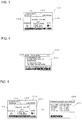
- Fig. 3 is a diagram illustrating an example of a main screen displayed on the display unit of the remote control device according to Embodiment 1.
- the display unit 3 displays a main screen 100, as illustrated in Fig. 3 .
- the main screen 100 is divided into a central section 101, an upper section 102, a left section 103, and a right section 104.
- the central section 101 the setting state of a set temperature, the indoor temperature, and other information are displayed.
- the upper section 102 the name of the remote controller, the date and time, and other information are displayed.
- the left section 103 the setting state of the operation mode and other information are displayed.
- the right section 104 the setting state of the wind direction, the wind speed, and other information are displayed.
- the user or the like is able to switch the setting state, such as the set temperature, the operation mode, the wind direction, and the wind speed, by pressing the function button 24 in the state in which the main screen 100 is being displayed on the display unit 3.
- the user or the like is able to reduce the set temperature of the air-conditioning apparatus or the like by pressing the function button 24 that is located below "-" displayed as a void character, from among the multiple function buttons 24, and increase the set temperature of the air-conditioning apparatus or the like by pressing the function button 24 that is located below "+” displayed as a void character.
- the main screen 100 corresponds to an "operation screen" according to the present invention.
- Fig. 4 is a diagram illustrating an example of a menu screen displayed on the display unit of the remote control device according to Embodiment 1.
- the display unit 3 displays a menu screen 200, as illustrated in Fig. 4 .
- items that may be executed by the user or the like are displayed as a list.
- the display unit 3 displays a screen for performing detailed settings of the operation state of the air-conditioning apparatus or the like, confirmation of apparatus type information of the air-conditioning apparatus or the like, and other types of processing.
- Fig. 5 is a diagram for explaining an operation of the display unit of the remote control device according to Embodiment 1.
- the display unit 3 displays a set temperature setting range display screen 300 that displays the range of the set temperature that may be set by the user or the like.
- each operation mode and the range of the set temperature that may be set are displayed in association with each other.
- the range of the set temperature that corresponds to the currently set operation mode may be displayed with emphasis.
- the letters “cooling”, the letters "19 degrees C to 30 degrees C” or the letters “cooling: 19 degrees C to 30 degrees C” may be displayed in a flashing manner.
- only the range of the set temperature that corresponds to the currently set operation mode may be displayed. With this operation, the user or the like is able to understand the currently set operation mode, without returning to the previous screen.
- the user or the like is able to change the set temperature after confirming the range of the set temperature that may be set in each operation mode. Therefore, a situation in which the user or the like unnecessarily presses a button or presses a button tentatively or other situations are suppressed, and the efficiency of a setting operation may thus be improved. Furthermore, the user or the like is able to display the set temperature setting range display screen 300 with a simple operation in the state in which the main screen 100 is being displayed, without operating the air-conditioning apparatus or the like. Therefore, the efficiency of an operation for confirming the range of the set temperature that may be set may be improved. Furthermore, on the set temperature setting range display screen 300, the user or the like is able to understand the currently set operation mode. Therefore, a complicated operation such as switching of the screen may be reduced, and the efficiency of a setting operation and a confirmation operation may thus be improved.
- a remote control device according to Embodiment 2 will be described.
- Embodiment 1 will be simplified or omitted in an appropriate manner.
- Figs. 6 and 7 are diagrams for explaining operations of a display unit of the remote control device according to Embodiment 2.
- the display unit 3 displays an upper limit value of the range of the set temperature that corresponds to the currently set operation mode in a set temperature setting range display part 110 that is provided in a blank of the main screen 100. Furthermore, as illustrated in Fig.
- the display unit 3 displays a lower limit value of the range of the set temperature that corresponds to the currently set operation mode in the set temperature setting range display part 110 that is provided in the blank of the main screen 100.
- the upper limit value or the lower limit value may be displayed in a flashing manner or a steady manner. Furthermore, the set temperature setting range display part 110 may be provided at a position different from the central part of the upper section 102. When the set temperature setting range display part 110 is provided at the central part of the upper section 102, emphasis display may be presented to the user or the like.
- the user or the like is able to change the set temperature after confirming the range of the set temperature that may be set in each operation mode. Therefore, the situation in which the user or the like unnecessarily presses a button or presses a button tentatively or other situations are suppressed, and the efficiency of a setting operation may thus be improved. Furthermore, the user or the like is able to display the upper limit value or the lower limit value in the set temperature setting range display part 110 with a simple operation in the state in which the main screen 100 is being displayed, without operating the air-conditioning apparatus or the like. Therefore, the efficiency of an operation for confirming the range of the set temperature that may be set may be improved. Furthermore, on main screen 100, the user or the like able to understand the range of the set temperature that may be set. Therefore, a complicated operation such as switching of the screen may be reduced, and the efficiency of a setting operation and a confirmation operation may be thus improved.
- a remote control device according to Embodiment 3 will be described.
- Embodiment 1 Embodiment 1
- Embodiment 2 Embodiment 2
- Fig. 8 is a diagram for explaining an operation of a display unit of the remote control device according to Embodiment 3.
- the display unit 3 displays an upper limit value or a lower limit value of the range of the set temperature that corresponds to the currently set operation mode in the set temperature setting range display part 110 that is provided in a blank of the main screen 100.
- the upper limit value and the lower limit value may be displayed in a flashing manner or a steady manner. Furthermore, the set temperature setting range display part 110 may be provided at a position different from the central part of the upper section 102. When the set temperature setting range display part 110 is provided at the central part of the upper section 102, emphasis display may be presented to the user or the like.
- the user or the like is able to change the set temperature after confirming the range of the set temperature that may be set in each operation mode. Therefore, the situation in which the user or the like unnecessarily presses a button or presses a button tentatively or other situations are suppressed, and the efficiency of a setting operation may thus be improved. Furthermore, the user or the like is able to display the upper limit value and the lower limit value in the set temperature setting range display part 110 with a simple operation in the state in which the main screen 100 is being displayed, without operating the air-conditioning apparatus or the like. Therefore, the efficiency of an operation for confirming the range of the set temperature that may be set may be improved.
- main screen 100 the user or the like is able to understand the range of the set temperature that may be set. Therefore, a complicated operation such as switching of the screen may be reduced, and the efficiency of a setting operation and a confirmation operation may thus be improved. Furthermore, both the upper limit value and the lower limit value are displayed in the set temperature setting range display part 110. Therefore, for example, even in the case where the user or the like intends to switch between increasing and decreasing of the set temperature after pressing the function button 24, the user or the like does not need to re-perform an operation for displaying the range of the set temperature that may be set on the display unit 3, and the efficiency of a setting operation and a confirmation operation may thus be improved.
- a remote control device according to Embodiment 4 will be described.
- Embodiment 1 to Embodiment 3 will be simplified or omitted in an appropriate manner.
- Fig. 9 is a diagram for explaining an operation of a display unit of the remote control device according to Embodiment 4.
- the display unit 3 displays an operation mode setting type display screen 400 that displays the type of operation mode that may be set by the user or the like.
- a central section 401 of the operation mode setting type display screen 400 individual operation modes are listed in order so that the order of transition of displayed operation mode may be presented when the function button 24 for changing the operation mode is repeatedly pressed.
- the currently set operation mode may be displayed with emphasis. For example, when the operation mode setting type display screen 400 is displayed in the state in which cooling (cooling operation) is set as the operation mode, the letters "cooling" may be displayed in a flashing manner. With this operation, the user or the like is able to understand the currently set operation mode, without returning to the previous screen.
- the user or the like is able to change the operation mode after confirming the type of operation mode that may be set and the display order for setting the operation mode. Therefore, the situation in which the user or the like unnecessarily presses a button or presses a button tentatively or other situations are suppressed even in the case where the type of operation mode that may be set or the display order for setting the operation mode varies according to the apparatus connected to the remote control device 1, and the efficiency of a setting operation may thus be improved. Furthermore, the user or the like is able to display the operation mode setting type display screen 400 with a simple operation in the state in which the main screen 100 is being displayed, without operating the air-conditioning apparatus or the like.
- the efficiency of an operation for confirming the type of operation mode that may be set and the display order of operation modes may be improved. Furthermore, on the operation mode setting type display screen 400, the user or the like is able to understand the currently set operation mode. Therefore, a complicated operation such as switching of the screen may be reduced, and the efficiency of a setting operation and a confirmation operation may thus be improved.
- a remote control device according to Embodiment 5 will be described.
- Embodiment 1 Embodiment 1
- Embodiment 4 Embodiment 4
- the display unit 3 displays a wind direction, louver, and ventilation setting screen 500.
- the contents of the wind direction, louver, and ventilation setting screen 500 may be displayed on the main screen 100. In such a case, the operation explained below is performed in the state in which the main screen 100 is being displayed.
- the wind direction, louver, and ventilation setting screen 500 corresponds to an "operation screen" according to the present invention.
- the wind direction, louver, and ventilation setting screen 500 is divided into a left section 501, a central section 502, a right section 503, and an upper section 504.
- the left section 501 the state in which a swing mode where the wind direction is variable is set, the state in which a fixed mode where the wind direction is not variable is set, the setting state of the wind direction in the fixed mode, and other information are displayed.
- the central section 502 the setting state of a ventilation operation and other information are displayed.
- the right section 503 the setting state of a louver and other information are displayed.
- Fig. 10 is a diagram for explaining an operation of a display unit of the remote control device according to Embodiment 5.
- the display unit 3 displays a wind direction setting type display screen 600 that displays the wind direction that may be set by the user or the like.
- a central section 601 of the wind direction setting type display screen 600 individual diagrams that indicate corresponding wind directions are listed in order so that the order of transition of displayed wind direction may be presented when the function button 24 for changing the wind direction is repeatedly pressed.
- the diagram that corresponds to the currently set wind direction may be displayed with emphasis.
- the letters "swinging" or other letters may be displayed.
- the fixed mode is set, the letters "fixed” or other letters may be displayed. With this operation, the user or the like is able to understand the currently set wind direction and mode, without returning to the previous screen.
- the user or the like is able to change the wind direction after confirming the type of wind direction that may be set and the display order for setting the wind direction. Therefore, the situation in which the user or the like unnecessarily presses a button or presses a button tentatively or other situations are suppressed even in the case where the type of wind direction that may be set or the display order for setting the wind direction varies according to the apparatus connected to the remote control device 1, and the efficiency of a setting operation may thus be improved. Furthermore, the user or the like is able to display the wind direction setting type display screen 600 with a simple operation in the state in which the wind direction, louver, and ventilation setting screen 500 is being displayed, without operating the air-conditioning apparatus or the like.
- the efficiency of an operation for confirming the type of wind direction that may be set and the display order for setting the wind direction may be improved. Furthermore, on the wind direction setting type display screen 600, the user or the like is able to understand the currently set wind direction and mode. Therefore, a complicated operation such as switching of the screen may be reduced, and the efficiency of a setting operation and a confirmation operation may thus be improved.
- a remote control device according to Embodiment 6 will be described.
- Embodiment 1 Embodiment 1
- Embodiment 5 Embodiment 5
- Figs. 11 and 12 are diagrams for explaining operations of a display unit of the remote control device according to Embodiment 6.
- the display unit 3 displays a wind direction setting upper limit display line 511 and a wind direction setting lower limit display line 512 in parts outside a wind direction display diagram 510 that displays the wind direction.
- the wind direction setting upper limit display line 511 is displayed, for example, above the wind direction display diagram 510 that indicates the most upward wind direction.
- the wind direction setting lower limit display line 512 is displayed, for example, beside the wind direction display diagram 510 that indicates the most downward wind direction. Both when the swing mode is set and when the wind direction at one of the multiple stages (for example, five states) is set in the fixed mode, the wind direction setting upper limit display line 511 and the wind direction setting lower limit display line 512 may be displayed.
- the wind direction setting upper limit display line 511 and the wind direction setting lower limit display line 512 may be displayed in a flashing manner or a steady manner.
- the user or the like is able to change the wind direction after confirming the range of the wind direction that may be set. Therefore, the situation in which the user or the like unnecessarily presses a button or presses a button tentatively or other situations are suppressed, and the efficiency of a setting operation may thus be improved. Furthermore, the user or the like is able to display the wind direction setting upper limit display line 511 and the wind direction setting lower limit display line 512 with a simple operation in the state in which the wind direction, louver, and ventilation setting screen 500 is being displayed, without operating the air-conditioning apparatus or the like. Therefore, the efficiency of an operation for confirming the range of the wind direction that may be set may be improved.
- louver, and ventilation setting screen 500 the user is able to understand the range of the wind direction that may be set. Therefore, a complicated operation such as switching of the screen may be reduced, and the efficiency of a setting operation and a confirmation operation may thus be improved.
- a remote control device according to Embodiment 7 will be described.
- Embodiment 1 to Embodiment 6 will be simplified or omitted in an appropriate manner.
- Fig. 13 is a diagram for explaining an operation of a display unit of the remote control device according to Embodiment 7.
- the display unit 3 displays a wind speed setting type display screen 700 that displays the type of wind speed that may be set by the user or the like.
- a void character in the right section 104 of the main screen 100 may be " 'upside down triangle' wind speed 'triangle' " or the like.
- the above-mentioned specific pressing registered in advance may be simultaneous pressing of the function button 24 that is located blow an "upside down triangle” displayed as a void character and the function button 24 that is located below a "triangle” displayed as a void character.
- a central section 701 of the wind speed setting type display screen 700 individual diagrams that indicate corresponding wind speeds are listed in order so that the order of transition of displayed wind direction may be presented when the function button 24 for changing the wind direction is repeatedly pressed.
- the currently set wind speed may be displayed with emphasis.
- the letters "automatic mode" or other letters may be displayed. With this operation, the user or the like is able to understand the currently set wind speed and mode, without returning to the previous screen.
- the user or the like is able to change the wind direction after confirming the type of wind speed that may be set and the display order for setting the wind speed. Therefore, the situation in which the user or the like unnecessarily presses a button or presses a button tentatively or other situations are suppressed even in the case where the type of wind speed that may be set or the display order for setting the wind speed varies according to the apparatus connected to the remote control device 1, and the efficiency of a setting operation may thus be improved. Furthermore, the user or the like is able to display the wind speed setting type display screen 700 with a simple operation in the state in which the main screen 100 is being displayed, without operating the air-conditioning apparatus or the like.
- the efficiency of an operation for confirming the type of wind speed that may be set and the display order of wind speeds may be improved. Furthermore, on the wind speed setting type display screen 700, the user or the like is able to understand the currently set wind speed and mode. Therefore, a complicated operation such as switching of the screen may be reduced, and the efficiency of a setting operation and a confirmation operation may thus be improved.
- a remote control device according to Embodiment 8 will be described.
- Embodiment 1 Embodiment 1
- Embodiment 7 Embodiment 7
- Fig. 14 is a diagram for explaining an operation of a display unit of the remote control device according to Embodiment 8.
- the display unit 3 displays a wind speed setting upper limit display line 121 in a part outside a wind speed display diagram 120 that displays the wind speed.
- the wind speed setting upper limit display line 121 is displayed, for example, beside the wind speed display diagram 120 that indicates the highest wind speed.
- the wind speed setting upper limit display line 121 may be displayed.
- the wind speed setting upper limit display line 121 may be displayed in a flashing manner or a steady manner.
- the user or the like is able to change the wind speed after confirming the range of the wind speed that may be set. Therefore, the situation in which the user or the like unnecessarily presses a button or presses a button tentatively or other situations are suppressed, and the efficiency of a setting operation may thus be improved. Furthermore, the user or the like is able to display the wind speed setting upper limit display line 121 with a simple operation in the state in which the main screen 100 is being displayed, without operating the air-conditioning apparatus or the like. Therefore, the efficiency of an operation for confirming the range of the wind speed that may be set may be improved. Furthermore, on main screen 100, the user or the like is able to understand the range of the wind speed that may be set. Therefore, a complicated operation such as switching of the screen may be reduced, and the efficiency of a setting operation and a confirmation operation may thus be improved.
- Embodiment 1 to Embodiment 8 will be simplified or omitted in an appropriate manner.
- Fig. 15 is a diagram illustrating an example of a menu screen displayed on a display unit of the remote control device according to Embodiment 9.
- the display unit 3 displays a menu screen 200, as illustrated in Fig. 15 .
- Fig. 16 is a diagram for explaining an operation of the display unit of the remote control device according to Embodiment 9.
- the display unit 3 displays the set temperature setting range display screen 300, as illustrated in Fig. 16 .
- the set temperature setting range display screen 300 when the user or the like repeatedly presses the function button 24 that is located below an "upside down triangle" displayed as a void character, the set temperature setting range display screen 300 is switched to the operation mode setting type display screen 400, the wind direction setting type display screen 600, and the wind speed setting type display screen 700, and then returns to the set temperature setting range display screen 300.
- the function button 24 that is located below a "triangle" displayed as a void character, the screen is switched in the inverse order.
- the user or the like is able to collectively confirm the range and type that may be set for individual settings as a series of screens. Therefore, the user or the like is able to easily confirm the range and type that may be set for the individual settings, without operating the connected air-conditioning apparatus or the like, and the efficiency of a setting operation and a confirmation operation may thus be improved.
- a remote control device according to Embodiment 10 will be described.
- Embodiment 1 to Embodiment 9 will be simplified or omitted in an appropriate manner.
- Fig. 17 is a diagram illustrating an example of a menu screen displayed on a display unit of the remote control device according to Embodiment 10.
- the display unit 3 displays a menu screen 200, as illustrated in Fig. 17 .
- Fig. 18 is a diagram for explaining an operation of the display unit of the remote control device according to Embodiment 10.
- the display unit 3 displays the set temperature setting range display screen 300, as illustrated in Fig. 18 .
- the set temperature setting range display screen 300 when the user or the like repeatedly presses the function button 24 that is located below an "upside down triangle" displayed as a void character, the set temperature setting range display screen 300 is switched to an apparatus type/function information display screen 800 and an operation mode information display screen 900, and then returns to the set temperature setting range display screen 300.
- the function button 24 that is located below a "triangle" displayed as a void character, the screen is switched in the inverse order.
- the apparatus type/function information display screen 800 for example, apparatus type information on the connected air-conditioning apparatus or the like, permission/prohibition of setting of wind speed and the number of stages that may be set, permission/prohibition of wind direction and the number of stages that may be set, presence/absence of a swing mode, presence/absence of a louver, and other information are displayed.
- the operation mode information display screen 900 for example, presence/absence of each operation mode and other information are displayed.
- the user or the like is able to collectively confirm the specifications of the connected air-conditioning apparatus or the like and the range of setting that may be set as a series of screens. Therefore, the user or the like is able to easily confirm the specifications of the connected air-conditioning apparatus or the like and the rage of setting that may be set, without operating the connected air-conditioning apparatus or the like, and the efficiency of a setting operation and a confirmation operation may thus be improved.
- Embodiments 1 to 10 have been described above. However, the present invention is not limited to the explanation for the above embodiments. For example, all or parts of the above embodiments may also be combined together. Furthermore, the contents explained for Embodiments 1 to 10 may be replaced with settings for other operations of the air-conditioning apparatus or the like.
Landscapes
- Engineering & Computer Science (AREA)
- Chemical & Material Sciences (AREA)
- Combustion & Propulsion (AREA)
- Mechanical Engineering (AREA)
- General Engineering & Computer Science (AREA)
- Signal Processing (AREA)
- Physics & Mathematics (AREA)
- Fuzzy Systems (AREA)
- Mathematical Physics (AREA)
- Human Computer Interaction (AREA)
- Air Conditioning Control Device (AREA)
- Selective Calling Equipment (AREA)
Abstract
Description
- The present invention relates to a remote control device.
- To apparatuses such as air-conditioning apparatuses, cooling energy apparatuses, and water heaters (hereinafter, described as air-conditioning apparatuses or the like), that is, apparatuses that perform at least one of a heating operation and a cooling operation, a remote control device is often attached so that a user or the like can set an operation state from a remote point. The user or the like can perform, for example, setting of operation and stop, setting of an operation mode, setting of an operation schedule, and other settings for various operations, by operating an operation unit provided at the remote control device. Furthermore, the user or the like can confirm the setting state, by viewing a display unit provided at the remote control device (see, for example,
Patent Literatures - For example, in the case where the remote control device is a remote control device for an air-conditioning apparatus, for example, buttons for setting operation and stop, a button for setting a set temperature, a button for setting an operation mode, a button for setting the wind direction, and other buttons are provided as the operation unit. For example, to change the operation state of the current indoor unit "operation, set temperature_23 degrees C, operation mode_cooling, and wind direction_downwards" into an operation state "operation, set temperature_25 degrees C, operation mode_heating, and wind direction_upwards", the user or the like presses a button for increasing the set temperature twice to switch the set temperature from 23 degrees C into 25 degrees C, presses a button for changing the operation mode three times to switch the operation mode in the order of cooling, drying, air-sending, and heating, and presses a button for changing the wind direction once to switch the wind direction from downward to upward.
-
- Patent Literature 1: Japanese Unexamined Patent Application Publication No.
2006-29687 Fig. 3 ) - Patent Literature 2: Japanese Unexamined Patent Application Publication No.
2-264597 Fig. 1 ) - In such a remote control device, the type, range, and the like of operation state that may be set can be known only after the operation unit is actually operated. Therefore, the user or the like needs to unnecessarily press a button to set the operation state and press the button tentatively, and this causes a problem that the efficiency of a setting operation is low. Furthermore, since the user or the like needs to operate the air-conditioning apparatus or the like to confirm the type, range, and the like of operation state that may be set, there is a problem that the efficiency of a confirmation operation is low.
- The present invention has been made in light of the above problems, and obtains a remote control device with improved efficiency of a setting operation and a confirmation operation.
- A remote control device according to the present invention includes an operation unit for switching and setting an operation state of an apparatus performing at least one of a heating operation and a cooling operation; a display unit that displays a screen on which an operation at the operation unit is reflected; and a controller that controls a display operation of the display unit. The controller causes the display unit to display at least one of a type and a range of an operation state that is able to be switched and set by the operation unit.
- In the remote control device according to the present invention, the controller causes the display unit to display at least one of the type and the range of operation state that may be switched and set by the operation unit. Therefore, the situation in which the user or the like unnecessarily presses a button or presses a button tentatively or other situations are suppressed, and the efficiency of a setting operation may thus be improved. Furthermore, the user or the like is able to confirm at least one of the type and the range of operation state that may be set, without operating the air-conditioning apparatus or the like, and the efficiency of a confirmation operation may thus be improved. Brief Description of Drawings
-
- [
Fig. 1] Fig. 1 is a diagram illustrating the external appearance of a remote control device according toEmbodiment 1. - [
Fig. 2] Fig. 2 is a diagram illustrating the system configuration of the remote control device according toEmbodiment 1. - [
Fig. 3] Fig. 3 is a diagram illustrating an example of a main screen displayed on a display unit of the remote control device according toEmbodiment 1. - [
Fig. 4] Fig. 4 is a diagram illustrating an example of a menu screen displayed on the display unit of the remote control device according toEmbodiment 1. - [
Fig. 5] Fig. 5 is a diagram for explaining an operation of the display unit of the remote control device according toEmbodiment 1. - [
Fig. 6] Fig. 6 is a diagram for explaining an operation of a display unit of a remote control device according toEmbodiment 2. - [
Fig. 7] Fig. 7 is a diagram for explaining an operation of the display unit of the remote control device according toEmbodiment 2. - [
Fig. 8] Fig. 8 is a diagram for explaining an operation of a display unit of a remote control device according toEmbodiment 3. - [
Fig. 9] Fig. 9 is a diagram for explaining an operation of a display unit of a remote control device according toEmbodiment 4. - [
Fig. 10] Fig. 10 is a diagram for explaining an operation of a display unit of a remote control device according toEmbodiment 5. - [
Fig. 11] Fig. 11 is a diagram for explaining an operation of a display unit of a remote control device according to Embodiment 6. - [
Fig. 12] Fig. 12 is a diagram for explaining an operation of the display unit of the remote control device according to Embodiment 6. - [
Fig. 13] Fig. 13 is a diagram for explaining an operation of a display unit of a remote control device according to Embodiment 7. - [
Fig. 14] Fig. 14 is a diagram for explaining an operation of a display unit of a remote control device according to Embodiment 8. - [
Fig. 15] Fig. 15 is a diagram illustrating an example of a menu screen displayed on a display unit of a remote control device according to Embodiment 9. - [
Fig. 16] Fig. 16 is a diagram for explaining an operation of the display unit of the remote control device according to Embodiment 9. - [
Fig. 17] Fig. 17 is a diagram illustrating an example of a menu screen displayed on a display unit of a remote control device according to Embodiment 10. - [
Fig. 18] Fig. 18 is a diagram for explaining an operation of the display unit of the remote control device according to Embodiment 10. - Hereinafter, remote control devices according to embodiments will be described with reference to the drawings.
- Configurations, operations, and the like explained below are merely examples. Remote control devices according to the present invention are not limited to cases with such configurations, operations, and the like. Furthermore, explanation for detailed configurations, operations, and the like are simplified or omitted in an appropriate manner. Furthermore, redundant and similar explanations will be simplified or omitted in an appropriate manner.
- A remote control device according to
Embodiment 1 will be described. - A configuration and an operation of the remote control device according to
Embodiment 1 will be described. -
Fig. 1 is a diagram illustrating the external appearance of the remote control device according toEmbodiment 1.Fig. 2 is a diagram illustrating the system configuration of the remote control device according toEmbodiment 1. - As illustrated in
Figs. 1 and 2 , aremote control device 1 includes anoperation unit 2, adisplay unit 3, acontroller 4, and a transmission/reception unit 5. - The
operation unit 2 includes an operation/stop button 21 for switching between operation and stop of the air-conditioning apparatus or the like, amenu button 22 for displaying a menu screen on thedisplay unit 3, a back button 23 for displaying on thedisplay unit 3 the last screen displayed before the screen that is currently being displayed,multiple function buttons 24 for switching settings on the screen displayed on thedisplay unit 3, and adetermination button 25 for determining the selection made on thedisplay unit 3. Theoperation unit 2 may include an up key, which is specified for increasing a set value or moving a cursor displayed on thedisplay unit 3 upwards. Furthermore, theoperation unit 2 may include a down key, which is specified for decreasing a set value or moving a cursor displayed on thedisplay unit 3 downwards. Furthermore, theoperation unit 2 may include a cross key, which is used for increasing or decreasing a set value or moving a cursor displayed on thedisplay unit 3 vertically and horizontally. At the center of the cross key, a button functioning as a determination button may be provided. - Information input by an operation on the
operation unit 2 by the user or the like is output to thecontroller 4. Furthermore, thecontroller 4 receives operation information and other types of information from the air-conditioning apparatus or the like via the transmission/reception unit 5. Thecontroller 4 generates, with a screen generator 4a, a screen that reflects the above information, and outputs the generated screen to thedisplay unit 3. Furthermore, when settings are switched due to an operation on theoperation unit 2 by the user or the like, thecontroller 4 transmits new setting information to the air-conditioning apparatus or the like. Thedisplay unit 3 displays the screen received from the screen generator 4a. Thedisplay unit 3 is, for example, a liquid crystal display, a PDP display, an organic EL display, an LED display, a CRT display, or other types of display. When thedisplay unit 3 is a liquid crystal display, the screen may be displayed in a dot matrix form. - The
remote control device 1 may be attached to an indoor wall surface or other places in a fixed manner or may be freely portable. Furthermore, the transmission/reception unit 5 may be connected to the air-conditioning apparatus or the like in a wired manner or may be connected to the air-conditioning apparatus or the like in a wireless manner. Furthermore, thedisplay unit 3 may be a touch panel or the like. That is, all or part of theoperation unit 2 may be incorporated as a soft key into the screen displayed on thedisplay unit 3. -
Fig. 3 is a diagram illustrating an example of a main screen displayed on the display unit of the remote control device according toEmbodiment 1. - During a normal operation, the
display unit 3 displays amain screen 100, as illustrated inFig. 3 . Themain screen 100 is divided into acentral section 101, anupper section 102, aleft section 103, and aright section 104. In thecentral section 101, the setting state of a set temperature, the indoor temperature, and other information are displayed. In theupper section 102, the name of the remote controller, the date and time, and other information are displayed. In theleft section 103, the setting state of the operation mode and other information are displayed. In theright section 104, the setting state of the wind direction, the wind speed, and other information are displayed. The user or the like is able to switch the setting state, such as the set temperature, the operation mode, the wind direction, and the wind speed, by pressing thefunction button 24 in the state in which themain screen 100 is being displayed on thedisplay unit 3. For example, the user or the like is able to reduce the set temperature of the air-conditioning apparatus or the like by pressing thefunction button 24 that is located below "-" displayed as a void character, from among themultiple function buttons 24, and increase the set temperature of the air-conditioning apparatus or the like by pressing thefunction button 24 that is located below "+" displayed as a void character. Themain screen 100 corresponds to an "operation screen" according to the present invention. -
Fig. 4 is a diagram illustrating an example of a menu screen displayed on the display unit of the remote control device according toEmbodiment 1. - When the user or the like presses the
menu button 22, thedisplay unit 3 displays amenu screen 200, as illustrated inFig. 4 . In anitem display section 201 of themenu screen 200, items that may be executed by the user or the like are displayed as a list. When the user or the like presses thefunction button 24 to move acursor 202 to a position beside a desired item and presses thedetermination button 25, thedisplay unit 3 displays a screen for performing detailed settings of the operation state of the air-conditioning apparatus or the like, confirmation of apparatus type information of the air-conditioning apparatus or the like, and other types of processing. -
Fig. 5 is a diagram for explaining an operation of the display unit of the remote control device according toEmbodiment 1. - As illustrated in
Fig. 5 , when the user or the like presses thefunction button 24 for changing the set temperature in a specific pressing manner registered in advance (for example, single pressing, continuous pressing for three seconds, double pressing, or other types of pressing) in the state in which themain screen 100 is being displayed on thedisplay unit 3, thedisplay unit 3 displays a set temperature settingrange display screen 300 that displays the range of the set temperature that may be set by the user or the like. - In a
central section 301 of the set temperature settingrange display screen 300, each operation mode and the range of the set temperature that may be set are displayed in association with each other. At this time, the range of the set temperature that corresponds to the currently set operation mode may be displayed with emphasis. For example, when the set temperature settingrange display screen 300 is displayed in the state in which the operation mode is set to cooling (cooling operation), the letters "cooling", the letters "19 degrees C to 30 degrees C" or the letters "cooling: 19 degrees C to 30 degrees C" may be displayed in a flashing manner. Furthermore, only the range of the set temperature that corresponds to the currently set operation mode may be displayed. With this operation, the user or the like is able to understand the currently set operation mode, without returning to the previous screen. - Effects of the remote control device according to
Embodiment 1 will be described. - In the
remote control device 1, the user or the like is able to change the set temperature after confirming the range of the set temperature that may be set in each operation mode. Therefore, a situation in which the user or the like unnecessarily presses a button or presses a button tentatively or other situations are suppressed, and the efficiency of a setting operation may thus be improved. Furthermore, the user or the like is able to display the set temperature settingrange display screen 300 with a simple operation in the state in which themain screen 100 is being displayed, without operating the air-conditioning apparatus or the like. Therefore, the efficiency of an operation for confirming the range of the set temperature that may be set may be improved. Furthermore, on the set temperature settingrange display screen 300, the user or the like is able to understand the currently set operation mode. Therefore, a complicated operation such as switching of the screen may be reduced, and the efficiency of a setting operation and a confirmation operation may thus be improved. - A remote control device according to
Embodiment 2 will be described. - Hereinafter, redundant explanations and explanations similar to
Embodiment 1 will be simplified or omitted in an appropriate manner. - A configuration and an operation of the remote control device according to
Embodiment 2 will be described. -
Figs. 6 and 7 are diagrams for explaining operations of a display unit of the remote control device according toEmbodiment 2. - As illustrated in
Fig. 6 , when the user or the like presses thefunction button 24 that is located below "+" displayed as a void character in a specific pressing manner registered in advance (for example, single pressing, continuous pressing for three seconds, double pressing, or other types of pressing) in the state in which themain screen 100 is being displayed on thedisplay unit 3, thedisplay unit 3 displays an upper limit value of the range of the set temperature that corresponds to the currently set operation mode in a set temperature settingrange display part 110 that is provided in a blank of themain screen 100. Furthermore, as illustrated inFig. 7 , when the user or the like presses thefunction button 24 that is located below "-" displayed as a void character in a specific pressing manner registered in advance (for example, single pressing, continuous pressing for three seconds, double pressing, or other types of pressing) in the state in which themain screen 100 is being displayed on thedisplay unit 3, thedisplay unit 3 displays a lower limit value of the range of the set temperature that corresponds to the currently set operation mode in the set temperature settingrange display part 110 that is provided in the blank of themain screen 100. - In the set temperature setting
range display part 110, the upper limit value or the lower limit value may be displayed in a flashing manner or a steady manner. Furthermore, the set temperature settingrange display part 110 may be provided at a position different from the central part of theupper section 102. When the set temperature settingrange display part 110 is provided at the central part of theupper section 102, emphasis display may be presented to the user or the like. - Effects of the remote control device according to
Embodiment 2 will be described. - In the
remote control device 1, the user or the like is able to change the set temperature after confirming the range of the set temperature that may be set in each operation mode. Therefore, the situation in which the user or the like unnecessarily presses a button or presses a button tentatively or other situations are suppressed, and the efficiency of a setting operation may thus be improved. Furthermore, the user or the like is able to display the upper limit value or the lower limit value in the set temperature settingrange display part 110 with a simple operation in the state in which themain screen 100 is being displayed, without operating the air-conditioning apparatus or the like. Therefore, the efficiency of an operation for confirming the range of the set temperature that may be set may be improved. Furthermore, onmain screen 100, the user or the like able to understand the range of the set temperature that may be set. Therefore, a complicated operation such as switching of the screen may be reduced, and the efficiency of a setting operation and a confirmation operation may be thus improved. - A remote control device according to
Embodiment 3 will be described. - Hereinafter, redundant explanations and explanations similar to
Embodiment 1 andEmbodiment 2 will be simplified or omitted in an appropriate manner. - A configuration and an operation of the remote control device according to
Embodiment 3 will be described. -
Fig. 8 is a diagram for explaining an operation of a display unit of the remote control device according toEmbodiment 3. - As illustrated in
Fig. 8 , when the user or the like presses thefunction button 24 that is located below "+" displayed as a void character or thefunction button 24 that is located below "-" displayed as a void character in a specific pressing manner registered in advance (for example, single pressing, continuous pressing for three seconds, double pressing, or other types of pressing) in the state in which themain screen 100 is being displayed on thedisplay unit 3, thedisplay unit 3 displays an upper limit value or a lower limit value of the range of the set temperature that corresponds to the currently set operation mode in the set temperature settingrange display part 110 that is provided in a blank of themain screen 100. - In the set temperature setting
range display part 110, the upper limit value and the lower limit value may be displayed in a flashing manner or a steady manner. Furthermore, the set temperature settingrange display part 110 may be provided at a position different from the central part of theupper section 102. When the set temperature settingrange display part 110 is provided at the central part of theupper section 102, emphasis display may be presented to the user or the like. - Effects of the remote control device according to
Embodiment 3 will be described. - In the
remote control device 1, the user or the like is able to change the set temperature after confirming the range of the set temperature that may be set in each operation mode. Therefore, the situation in which the user or the like unnecessarily presses a button or presses a button tentatively or other situations are suppressed, and the efficiency of a setting operation may thus be improved. Furthermore, the user or the like is able to display the upper limit value and the lower limit value in the set temperature settingrange display part 110 with a simple operation in the state in which themain screen 100 is being displayed, without operating the air-conditioning apparatus or the like. Therefore, the efficiency of an operation for confirming the range of the set temperature that may be set may be improved. Furthermore, onmain screen 100, the user or the like is able to understand the range of the set temperature that may be set. Therefore, a complicated operation such as switching of the screen may be reduced, and the efficiency of a setting operation and a confirmation operation may thus be improved. Furthermore, both the upper limit value and the lower limit value are displayed in the set temperature settingrange display part 110. Therefore, for example, even in the case where the user or the like intends to switch between increasing and decreasing of the set temperature after pressing thefunction button 24, the user or the like does not need to re-perform an operation for displaying the range of the set temperature that may be set on thedisplay unit 3, and the efficiency of a setting operation and a confirmation operation may thus be improved. - A remote control device according to
Embodiment 4 will be described. - Hereinafter, redundant explanations and explanations similar to
Embodiment 1 toEmbodiment 3 will be simplified or omitted in an appropriate manner. - A configuration and an operation of the remote control device according to
Embodiment 4 will be described. -
Fig. 9 is a diagram for explaining an operation of a display unit of the remote control device according toEmbodiment 4. - As illustrated in
Fig. 9 , when the user or the like presses thefunction button 24 for changing the operation mode in a specific pressing manner registered in advance (for example, single pressing, continuous pressing for three seconds, double pressing, or other types of pressing) in the state in which themain screen 100 is being displayed on thedisplay unit 3, thedisplay unit 3 displays an operation mode settingtype display screen 400 that displays the type of operation mode that may be set by the user or the like. - In a
central section 401 of the operation mode settingtype display screen 400, individual operation modes are listed in order so that the order of transition of displayed operation mode may be presented when thefunction button 24 for changing the operation mode is repeatedly pressed. At this time, the currently set operation mode may be displayed with emphasis. For example, when the operation mode settingtype display screen 400 is displayed in the state in which cooling (cooling operation) is set as the operation mode, the letters "cooling" may be displayed in a flashing manner. With this operation, the user or the like is able to understand the currently set operation mode, without returning to the previous screen. - Effects of the remote control device according to
Embodiment 4 will be described. - In the
remote control device 1, the user or the like is able to change the operation mode after confirming the type of operation mode that may be set and the display order for setting the operation mode. Therefore, the situation in which the user or the like unnecessarily presses a button or presses a button tentatively or other situations are suppressed even in the case where the type of operation mode that may be set or the display order for setting the operation mode varies according to the apparatus connected to theremote control device 1, and the efficiency of a setting operation may thus be improved. Furthermore, the user or the like is able to display the operation mode settingtype display screen 400 with a simple operation in the state in which themain screen 100 is being displayed, without operating the air-conditioning apparatus or the like. Therefore, the efficiency of an operation for confirming the type of operation mode that may be set and the display order of operation modes may be improved. Furthermore, on the operation mode settingtype display screen 400, the user or the like is able to understand the currently set operation mode. Therefore, a complicated operation such as switching of the screen may be reduced, and the efficiency of a setting operation and a confirmation operation may thus be improved. - A remote control device according to
Embodiment 5 will be described. - Hereinafter, redundant explanations and explanations similar to
Embodiment 1 toEmbodiment 4 will be simplified or omitted in an appropriate manner. - A configuration and an operation of the remote control device according to
Embodiment 5 will be described. - When the user or the like moves the
cursor 202 to a position beside the letters "wind direction/louver/ventilation operation" and presses thedetermination button 25 in the state in which themenu screen 200 illustrated inFig. 4 is being displayed, thedisplay unit 3 displays a wind direction, louver, andventilation setting screen 500. The contents of the wind direction, louver, andventilation setting screen 500 may be displayed on themain screen 100. In such a case, the operation explained below is performed in the state in which themain screen 100 is being displayed. The wind direction, louver, andventilation setting screen 500 corresponds to an "operation screen" according to the present invention. - The wind direction, louver, and
ventilation setting screen 500 is divided into aleft section 501, acentral section 502, aright section 503, and anupper section 504. In theleft section 501, the state in which a swing mode where the wind direction is variable is set, the state in which a fixed mode where the wind direction is not variable is set, the setting state of the wind direction in the fixed mode, and other information are displayed. In thecentral section 502, the setting state of a ventilation operation and other information are displayed. In theright section 503, the setting state of a louver and other information are displayed. -
Fig. 10 is a diagram for explaining an operation of a display unit of the remote control device according toEmbodiment 5. - As illustrated in
Fig. 10 , when the user or the like presses thefunction button 24 for changing the wind direction in a specific pressing manner registered in advance (for example, single pressing, continuous pressing for three seconds, double pressing, simultaneous pressing of thefunction button 24 that is located below an "upside down triangle" displayed as a void character and thefunction button 24 that is located below a "triangle" displayed as a void character, or other types of pressing) in the state in which the wind direction, louver, andventilation setting screen 500 is being displayed on thedisplay unit 3, thedisplay unit 3 displays a wind direction settingtype display screen 600 that displays the wind direction that may be set by the user or the like. - In a
central section 601 of the wind direction settingtype display screen 600, individual diagrams that indicate corresponding wind directions are listed in order so that the order of transition of displayed wind direction may be presented when thefunction button 24 for changing the wind direction is repeatedly pressed. At this time, the diagram that corresponds to the currently set wind direction may be displayed with emphasis. Furthermore, if the swing mode is set, the letters "swinging" or other letters may be displayed. If the fixed mode is set, the letters "fixed" or other letters may be displayed. With this operation, the user or the like is able to understand the currently set wind direction and mode, without returning to the previous screen. - Effects of the remote control device according to
Embodiment 5 will be described. - In the
remote control device 1, the user or the like is able to change the wind direction after confirming the type of wind direction that may be set and the display order for setting the wind direction. Therefore, the situation in which the user or the like unnecessarily presses a button or presses a button tentatively or other situations are suppressed even in the case where the type of wind direction that may be set or the display order for setting the wind direction varies according to the apparatus connected to theremote control device 1, and the efficiency of a setting operation may thus be improved. Furthermore, the user or the like is able to display the wind direction settingtype display screen 600 with a simple operation in the state in which the wind direction, louver, andventilation setting screen 500 is being displayed, without operating the air-conditioning apparatus or the like. Therefore, the efficiency of an operation for confirming the type of wind direction that may be set and the display order for setting the wind direction may be improved. Furthermore, on the wind direction settingtype display screen 600, the user or the like is able to understand the currently set wind direction and mode. Therefore, a complicated operation such as switching of the screen may be reduced, and the efficiency of a setting operation and a confirmation operation may thus be improved. - A remote control device according to Embodiment 6 will be described.
- Hereinafter, redundant explanations and explanations similar to
Embodiment 1 toEmbodiment 5 will be simplified or omitted in an appropriate manner. - A configuration and an operation of the remote control device according to Embodiment 6 will be described.
-
Figs. 11 and12 are diagrams for explaining operations of a display unit of the remote control device according to Embodiment 6. - As illustrated in
Figs. 11 and12 , in the case where the swing mode is set or the wind direction at one of multiple stages (for example, five stages) is set in the fixed mode, when the user or the like presses thefunction button 24 for changing the wind direction in a specific pressing manner registered in advance (for example, single pressing, continuous pressing for three seconds, double pressing, simultaneous pressing of thefunction button 24 that is located below an "upside down triangle" displayed as a void character and thefunction button 24 that is located below a "triangle" displayed as a void character, or other types of pressing) in the state in which the wind direction, louver, andventilation setting screen 500 is being displayed on thedisplay unit 3, thedisplay unit 3 displays a wind direction setting upperlimit display line 511 and a wind direction setting lowerlimit display line 512 in parts outside a wind direction display diagram 510 that displays the wind direction. The wind direction setting upperlimit display line 511 is displayed, for example, above the wind direction display diagram 510 that indicates the most upward wind direction. The wind direction setting lowerlimit display line 512 is displayed, for example, beside the wind direction display diagram 510 that indicates the most downward wind direction. Both when the swing mode is set and when the wind direction at one of the multiple stages (for example, five states) is set in the fixed mode, the wind direction setting upperlimit display line 511 and the wind direction setting lowerlimit display line 512 may be displayed. The wind direction setting upperlimit display line 511 and the wind direction setting lowerlimit display line 512 may be displayed in a flashing manner or a steady manner. - Effects of the remote control device according to Embodiment 6 will be described.
- In the
remote control device 1, the user or the like is able to change the wind direction after confirming the range of the wind direction that may be set. Therefore, the situation in which the user or the like unnecessarily presses a button or presses a button tentatively or other situations are suppressed, and the efficiency of a setting operation may thus be improved. Furthermore, the user or the like is able to display the wind direction setting upperlimit display line 511 and the wind direction setting lowerlimit display line 512 with a simple operation in the state in which the wind direction, louver, andventilation setting screen 500 is being displayed, without operating the air-conditioning apparatus or the like. Therefore, the efficiency of an operation for confirming the range of the wind direction that may be set may be improved. Furthermore, on the wind direction, louver, andventilation setting screen 500, the user is able to understand the range of the wind direction that may be set. Therefore, a complicated operation such as switching of the screen may be reduced, and the efficiency of a setting operation and a confirmation operation may thus be improved. - A remote control device according to Embodiment 7 will be described.
- Hereinafter, redundant explanations and explanations similar to
Embodiment 1 to Embodiment 6 will be simplified or omitted in an appropriate manner. - A configuration and an operation of the remote control device according to Embodiment 7 will be described.
-
Fig. 13 is a diagram for explaining an operation of a display unit of the remote control device according to Embodiment 7. - As illustrated in
Fig. 13 , when the user or the like presses thefunction button 24 for changing the wind speed in a specific pressing manner registered in advance (for example, single pressing, continuous pressing for three seconds, double pressing, or other types of pressing) in the state in which themain screen 100 is being displayed on thedisplay unit 3, thedisplay unit 3 displays a wind speed settingtype display screen 700 that displays the type of wind speed that may be set by the user or the like. A void character in theright section 104 of themain screen 100 may be " 'upside down triangle' wind speed 'triangle' " or the like. In such a case, the above-mentioned specific pressing registered in advance may be simultaneous pressing of thefunction button 24 that is located blow an "upside down triangle" displayed as a void character and thefunction button 24 that is located below a "triangle" displayed as a void character. - In a
central section 701 of the wind speed settingtype display screen 700, individual diagrams that indicate corresponding wind speeds are listed in order so that the order of transition of displayed wind direction may be presented when thefunction button 24 for changing the wind direction is repeatedly pressed. At this time, the currently set wind speed may be displayed with emphasis. Furthermore, if an automatic mode where the wind speed is automatically set is set, the letters "automatic mode" or other letters may be displayed. With this operation, the user or the like is able to understand the currently set wind speed and mode, without returning to the previous screen. - Effects of the remote control device according to Embodiment 7 will be described.
- In the
remote control device 1, the user or the like is able to change the wind direction after confirming the type of wind speed that may be set and the display order for setting the wind speed. Therefore, the situation in which the user or the like unnecessarily presses a button or presses a button tentatively or other situations are suppressed even in the case where the type of wind speed that may be set or the display order for setting the wind speed varies according to the apparatus connected to theremote control device 1, and the efficiency of a setting operation may thus be improved. Furthermore, the user or the like is able to display the wind speed settingtype display screen 700 with a simple operation in the state in which themain screen 100 is being displayed, without operating the air-conditioning apparatus or the like. Therefore, the efficiency of an operation for confirming the type of wind speed that may be set and the display order of wind speeds may be improved. Furthermore, on the wind speed settingtype display screen 700, the user or the like is able to understand the currently set wind speed and mode. Therefore, a complicated operation such as switching of the screen may be reduced, and the efficiency of a setting operation and a confirmation operation may thus be improved. - A remote control device according to Embodiment 8 will be described.
- Hereinafter, redundant explanations and explanations similar to
Embodiment 1 to Embodiment 7 will be simplified or omitted in an appropriate manner. - A configuration and an operation of the remote control device according to Embodiment 8 will be described.
-
Fig. 14 is a diagram for explaining an operation of a display unit of the remote control device according to Embodiment 8. - As illustrated in
Fig. 14 , in the case where the wind speed at one of multiple stages (for example, four stages) is set or the automatic mode is set, when the user or the like presses thefunction button 24 for changing the wind speed in a specific pressing manner registered in advance (for example, single pressing, continuous pressing for three seconds, double pressing, or other types of pressing) in the state in which themain screen 100 is being displayed on thedisplay unit 3, thedisplay unit 3 displays a wind speed setting upperlimit display line 121 in a part outside a wind speed display diagram 120 that displays the wind speed. The wind speed setting upperlimit display line 121 is displayed, for example, beside the wind speed display diagram 120 that indicates the highest wind speed. Both when the wind speed at one of the multiple stages (for example, four stages) is set and when the automatic mode is set, the wind speed setting upperlimit display line 121 may be displayed. The wind speed setting upperlimit display line 121 may be displayed in a flashing manner or a steady manner. - Effects of the remote control device according to Embodiment 8 will be described.
- In the
remote control device 1, the user or the like is able to change the wind speed after confirming the range of the wind speed that may be set. Therefore, the situation in which the user or the like unnecessarily presses a button or presses a button tentatively or other situations are suppressed, and the efficiency of a setting operation may thus be improved. Furthermore, the user or the like is able to display the wind speed setting upperlimit display line 121 with a simple operation in the state in which themain screen 100 is being displayed, without operating the air-conditioning apparatus or the like. Therefore, the efficiency of an operation for confirming the range of the wind speed that may be set may be improved. Furthermore, onmain screen 100, the user or the like is able to understand the range of the wind speed that may be set. Therefore, a complicated operation such as switching of the screen may be reduced, and the efficiency of a setting operation and a confirmation operation may thus be improved. - A remote control device according to Embodiment 9 will be described.
- Hereinafter, redundant explanations and explanations similar to
Embodiment 1 to Embodiment 8 will be simplified or omitted in an appropriate manner. - A configuration and an operation of the remote control device according to Embodiment 9 will be described.
-
Fig. 15 is a diagram illustrating an example of a menu screen displayed on a display unit of the remote control device according to Embodiment 9. - When the user or the like presses the
menu button 22, thedisplay unit 3 displays amenu screen 200, as illustrated inFig. 15 . -
Fig. 16 is a diagram for explaining an operation of the display unit of the remote control device according to Embodiment 9. - When the user or the like moves the
cursor 202 to a position beside the letters "operation/setting range monitor" and presses thedetermination button 25 in the state in which themenu screen 200 is being displayed, thedisplay unit 3 displays the set temperature settingrange display screen 300, as illustrated inFig. 16 . On the set temperature settingrange display screen 300, when the user or the like repeatedly presses thefunction button 24 that is located below an "upside down triangle" displayed as a void character, the set temperature settingrange display screen 300 is switched to the operation mode settingtype display screen 400, the wind direction settingtype display screen 600, and the wind speed settingtype display screen 700, and then returns to the set temperature settingrange display screen 300. When the user or the like presses thefunction button 24 that is located below a "triangle" displayed as a void character, the screen is switched in the inverse order. - Effects of the remote control device according to Embodiment 9 will be described.
- In the
remote control device 1, after themain screen 100 is switched to themenu screen 200, the user or the like is able to collectively confirm the range and type that may be set for individual settings as a series of screens. Therefore, the user or the like is able to easily confirm the range and type that may be set for the individual settings, without operating the connected air-conditioning apparatus or the like, and the efficiency of a setting operation and a confirmation operation may thus be improved. - A remote control device according to Embodiment 10 will be described.
- Hereinafter, redundant explanations and explanations similar to
Embodiment 1 to Embodiment 9 will be simplified or omitted in an appropriate manner. - A configuration and an operation of the remote control device according to Embodiment 10 will be described.
-
Fig. 17 is a diagram illustrating an example of a menu screen displayed on a display unit of the remote control device according to Embodiment 10. - When the user or the like presses the
menu button 22, thedisplay unit 3 displays amenu screen 200, as illustrated inFig. 17 . -
Fig. 18 is a diagram for explaining an operation of the display unit of the remote control device according to Embodiment 10. - When the user or the like moves the
cursor 202 to a position beside the letters "connected unit information" and presses thedetermination button 25 in the state in which themenu screen 200 is being displayed, thedisplay unit 3 displays the set temperature settingrange display screen 300, as illustrated inFig. 18 . On the set temperature settingrange display screen 300, when the user or the like repeatedly presses thefunction button 24 that is located below an "upside down triangle" displayed as a void character, the set temperature settingrange display screen 300 is switched to an apparatus type/functioninformation display screen 800 and an operation modeinformation display screen 900, and then returns to the set temperature settingrange display screen 300. When the user or the like presses thefunction button 24 that is located below a "triangle" displayed as a void character, the screen is switched in the inverse order. - On the apparatus type/function
information display screen 800, for example, apparatus type information on the connected air-conditioning apparatus or the like, permission/prohibition of setting of wind speed and the number of stages that may be set, permission/prohibition of wind direction and the number of stages that may be set, presence/absence of a swing mode, presence/absence of a louver, and other information are displayed. On the operation modeinformation display screen 900, for example, presence/absence of each operation mode and other information are displayed. - Effects of the remote control device according to Embodiment 10 will be described.
- In the
remote control device 1, after themain screen 100 is switched to themenu screen 200, the user or the like is able to collectively confirm the specifications of the connected air-conditioning apparatus or the like and the range of setting that may be set as a series of screens. Therefore, the user or the like is able to easily confirm the specifications of the connected air-conditioning apparatus or the like and the rage of setting that may be set, without operating the connected air-conditioning apparatus or the like, and the efficiency of a setting operation and a confirmation operation may thus be improved. -
Embodiments 1 to 10 have been described above. However, the present invention is not limited to the explanation for the above embodiments. For example, all or parts of the above embodiments may also be combined together. Furthermore, the contents explained forEmbodiments 1 to 10 may be replaced with settings for other operations of the air-conditioning apparatus or the like. -
- 1: remote control device, 2: operation unit, 3 display unit, 4 controller, 4a: screen generator, 5: transmission/reception unit, 21: operation/stop button, 22: menu button, 23: back button, 24: function button, 25: determination button, 100: main screen, 101: central section, 102: upper section, 103: left section, 104: right section, 110: set temperature setting range display part, 120: wind speed display diagram, 121: wind speed setting upper limit display line, 200: menu screen, 201: item display section, 202: cursor, 300: set temperature setting range display screen, 301: central section, 400: operation mode setting type display screen, 401: central section, 500: wind direction/louver/ventilation setting screen, 501: left section, 502: central section, 503: right section, 504: upper section, 510: wind direction display diagram, 511: wind direction setting upper limit display line, 512: wind direction setting lower limit display line, 600: wind direction setting type display screen, 601: central section, 700: wind speed setting type display screen, 701: central section, 800: apparatus type information/function information display screen, 900: operation mode information display screen.
Claims (10)
- A remote control device comprising:an operation unit configured to switch and set an operation state of an apparatus performing at least one of a heating operation and a cooling operation;a display unit configured to display a screen on which an operation at the operation unit is reflected; anda controller configured to control a display operation of the display unit,wherein the controller causes the display unit to display at least one of a type and a range of an operation state that is able to be switched and set by the operation unit.
- The remote control device of claim 1, wherein
the controller causes the display unit to display a type of an operation mode that is able to be switched and set by the operation unit. - The remote control device of claim 1 or 2, wherein
the controller causes the display unit to display a range of a set temperature that is able to be switched and set by the operation unit. - The remote control device of claim 3, wherein
the controller causes the display unit to display the range of the set temperature in association with an operation mode. - The remote control device of any one of claims 1 to 4, wherein
the controller causes the display unit to display at least one of a type and a range of a wind direction that is able to be switched and set by the operation unit. - The remote control device of any one of claims 1 to 5, wherein
the controller causes the display unit to display at least one of a type and a range of a wind speed that is able to be switched and set by the operation unit. - The remote control device of any one of claims 1 to 6, wherein
the controller causes the display unit to display, as a list, the type of the operation state that is able to be switched and set by the operation unit. - The remote control device of claim 7, wherein
the controller causes the display unit to display, as a list, types of the operation state in an order in which the types of the operation state are switched by an operation at the operation unit. - The remote control device of any one of claims 1 to 8, wherein
the controller causes the display unit to display the range of the operation state that is able to be switched and set by the operation unit in a state in which an operation screen is being displayed. - The remote control device of any one of claims 1 to 9, wherein
the controller causes the display unit to display, as a series of screens, at least one of the type and the range of the operation state that is able to be switched and set by the operation unit and at least one of apparatus type information and function information of the apparatus.
Applications Claiming Priority (1)
| Application Number | Priority Date | Filing Date | Title |
|---|---|---|---|
| PCT/JP2013/077422 WO2015052786A1 (en) | 2013-10-09 | 2013-10-09 | Remote control device |
Publications (3)
| Publication Number | Publication Date |
|---|---|
| EP3056831A1 true EP3056831A1 (en) | 2016-08-17 |
| EP3056831A4 EP3056831A4 (en) | 2017-05-17 |
| EP3056831B1 EP3056831B1 (en) | 2022-12-07 |
Family
ID=52812634
Family Applications (1)
| Application Number | Title | Priority Date | Filing Date |
|---|---|---|---|
| EP13895440.9A Active EP3056831B1 (en) | 2013-10-09 | 2013-10-09 | Remote control device |
Country Status (5)
| Country | Link |
|---|---|
| US (1) | US10598400B2 (en) |
| EP (1) | EP3056831B1 (en) |
| JP (1) | JP6091638B2 (en) |
| CN (1) | CN105393060A (en) |
| WO (1) | WO2015052786A1 (en) |
Families Citing this family (10)
| Publication number | Priority date | Publication date | Assignee | Title |
|---|---|---|---|---|
| US20160174146A1 (en) * | 2014-12-15 | 2016-06-16 | Xiaomi Inc. | Method and device for connecting appliance to network |
| KR101747355B1 (en) * | 2015-12-23 | 2017-06-14 | 엘지전자 주식회사 | Input device and air conditioner including the same |
| JP6252607B2 (en) | 2016-01-21 | 2017-12-27 | ダイキン工業株式会社 | Remote control device |
| CN106382713A (en) * | 2016-08-29 | 2017-02-08 | 珠海格力电器股份有限公司 | Air conditioner and control method thereof, air conditioner remote control equipment and remote control method thereof, and air conditioning system |
| CN108954495B (en) * | 2017-05-17 | 2020-12-15 | 奥克斯空调股份有限公司 | Control method of air conditioner indoor unit |
| JP6551756B2 (en) * | 2017-12-06 | 2019-07-31 | Toto株式会社 | Remote control device and water system |
| CN111771088B (en) * | 2018-02-16 | 2021-08-10 | 三菱电机株式会社 | Remote controller for air conditioner |
| JP7194166B2 (en) * | 2018-03-13 | 2022-12-21 | 三菱電機株式会社 | Operating device for air conditioner and air conditioner |
| USD977996S1 (en) | 2020-12-18 | 2023-02-14 | Research Products Corporation | Heating ventilation and air conditioning controller |
| USD977343S1 (en) | 2021-03-09 | 2023-02-07 | Research Products Corporation | Heating ventilation and air conditioning controller |
Family Cites Families (22)
| Publication number | Priority date | Publication date | Assignee | Title |
|---|---|---|---|---|
| JPH02264597A (en) | 1989-04-04 | 1990-10-29 | Seiko Epson Corp | remote control device |
| JPH0576087A (en) * | 1991-09-12 | 1993-03-26 | Seiko Epson Corp | Remote control device |
| JP2702834B2 (en) * | 1991-10-23 | 1998-01-26 | 松下精工株式会社 | Control device for air conditioner |
| US5180333A (en) * | 1991-10-28 | 1993-01-19 | Norm Pacific Automation Corp. | Ventilation device adjusted and controlled automatically with movement of human body |
| JP3108163B2 (en) * | 1991-10-31 | 2000-11-13 | 三洋電機株式会社 | Air conditioner |
| JP3453791B2 (en) | 1993-07-06 | 2003-10-06 | 三菱電機株式会社 | Air conditioner and remote control device for air conditioner |
| JP2000257943A (en) | 1999-03-11 | 2000-09-22 | Funai Electric Co Ltd | Air conditioner |
| JP2001153440A (en) * | 1999-11-29 | 2001-06-08 | Funai Electric Co Ltd | Air conditioner |
| JP4229019B2 (en) | 2004-07-16 | 2009-02-25 | 三菱電機株式会社 | Air conditioner |
| US8172153B1 (en) * | 2004-12-30 | 2012-05-08 | Kennedy Metal Products & Buildings, Inc. | Energy usage control for a building |
| KR20070080293A (en) | 2006-02-07 | 2007-08-10 | 엘지전자 주식회사 | How to mark anniversary on air conditioner with display unit |
| JP2009002593A (en) | 2007-06-22 | 2009-01-08 | Nippon Seiki Co Ltd | Air conditioner control device |
| US20110132991A1 (en) * | 2009-12-07 | 2011-06-09 | Hunter Fan Company | Thermostat |
| US8556188B2 (en) * | 2010-05-26 | 2013-10-15 | Ecofactor, Inc. | System and method for using a mobile electronic device to optimize an energy management system |
| JP5470457B2 (en) | 2010-06-25 | 2014-04-16 | 東芝キヤリア株式会社 | Air conditioning system |
| US10241527B2 (en) * | 2010-11-19 | 2019-03-26 | Google Llc | Thermostat graphical user interface |
| CN102486328A (en) * | 2010-12-02 | 2012-06-06 | 乐金电子(天津)电器有限公司 | Gravity sensing control method for remote control of air-conditioner |
| CN202328630U (en) * | 2011-12-07 | 2012-07-11 | Tcl空调器(中山)有限公司 | Dual remote air conditioner |
| US9002523B2 (en) * | 2011-12-14 | 2015-04-07 | Honeywell International Inc. | HVAC controller with diagnostic alerts |
| CN102519117A (en) * | 2011-12-23 | 2012-06-27 | 广东美的电器股份有限公司 | Remote control system for air conditioner |
| US9122283B2 (en) * | 2013-04-19 | 2015-09-01 | Emerson Electric Co. | Battery power management in a thermostat with a wireless transceiver |
| KR20150038977A (en) * | 2013-10-01 | 2015-04-09 | 엘지전자 주식회사 | heating, ventilation, and/or air conditioning controller |
-
2013
- 2013-10-09 US US14/899,783 patent/US10598400B2/en active Active
- 2013-10-09 JP JP2015541345A patent/JP6091638B2/en active Active
- 2013-10-09 EP EP13895440.9A patent/EP3056831B1/en active Active
- 2013-10-09 WO PCT/JP2013/077422 patent/WO2015052786A1/en not_active Ceased
- 2013-10-09 CN CN201380078343.3A patent/CN105393060A/en active Pending
Also Published As
| Publication number | Publication date |
|---|---|
| CN105393060A (en) | 2016-03-09 |
| WO2015052786A1 (en) | 2015-04-16 |
| US10598400B2 (en) | 2020-03-24 |
| EP3056831B1 (en) | 2022-12-07 |
| JP6091638B2 (en) | 2017-03-08 |
| US20160138820A1 (en) | 2016-05-19 |
| EP3056831A4 (en) | 2017-05-17 |
| JPWO2015052786A1 (en) | 2017-03-09 |
Similar Documents
| Publication | Publication Date | Title |
|---|---|---|
| EP3056831B1 (en) | Remote control device | |
| US10764157B2 (en) | Control apparatus for controlling an operation of at least one electronic device | |
| US10608837B2 (en) | Control apparatus and method for controlling the same | |
| US10120532B2 (en) | Control apparatus for controlling an operation of at least one electronic device | |
| US10592062B2 (en) | Control apparatus | |
| CN101668995A (en) | air-conditioning controller | |
| JP6079358B2 (en) | Air conditioner remote control device | |
| JP2016130620A (en) | Air conditioning control terminal and air conditioning system | |
| EP3567837A1 (en) | Radio communication system | |
| US11205055B2 (en) | Management device and air-conditioning system | |
| US10627981B2 (en) | Operation apparatus | |
| JP6400213B2 (en) | Remote controller | |
| EP3806481B1 (en) | Equipment management device using touch panel, and method for generating management screen | |
| US11859844B2 (en) | Air conditioner management device, and air conditioner management screen generation method | |
| EP4471561A1 (en) | Operation terminal device and display control method for user interface of said operation terminal device | |
| JP7211012B2 (en) | Remote controller for air conditioner | |
| JP2009276037A (en) | Remote controller for bathroom ventilation air-conditioning device | |
| US20160003494A1 (en) | Actuator controlling device for construction equipment and actuator controlling method therefor | |
| WO2017212614A1 (en) | Ac controller and air conditioning control management system | |
| EP4113234A1 (en) | Equipment management device and method for generating equipment management screen | |
| JP2011214774A (en) | Centralized controller for air conditioner | |
| JP2014232580A (en) | Illumination control device and building management system including the same |
Legal Events
| Date | Code | Title | Description |
|---|---|---|---|
| PUAI | Public reference made under article 153(3) epc to a published international application that has entered the european phase |
Free format text: ORIGINAL CODE: 0009012 |
|
| 17P | Request for examination filed |
Effective date: 20160105 |
|
| AK | Designated contracting states |
Kind code of ref document: A1 Designated state(s): AL AT BE BG CH CY CZ DE DK EE ES FI FR GB GR HR HU IE IS IT LI LT LU LV MC MK MT NL NO PL PT RO RS SE SI SK SM TR |
|
| AX | Request for extension of the european patent |
Extension state: BA ME |
|
| DAX | Request for extension of the european patent (deleted) | ||
| A4 | Supplementary search report drawn up and despatched |
Effective date: 20170418 |
|
| RIC1 | Information provided on ipc code assigned before grant |
Ipc: F24F 11/00 20060101AFI20170410BHEP |
|
| STAA | Information on the status of an ep patent application or granted ep patent |
Free format text: STATUS: EXAMINATION IS IN PROGRESS |
|
| 17Q | First examination report despatched |
Effective date: 20190827 |
|
| REG | Reference to a national code |
Ref country code: DE Ref legal event code: R079 Ref document number: 602013083029 Country of ref document: DE Free format text: PREVIOUS MAIN CLASS: F24F0011020000 Ipc: F24F0011300000 |
|
| GRAP | Despatch of communication of intention to grant a patent |
Free format text: ORIGINAL CODE: EPIDOSNIGR1 |
|
| STAA | Information on the status of an ep patent application or granted ep patent |
Free format text: STATUS: GRANT OF PATENT IS INTENDED |
|
| RIC1 | Information provided on ipc code assigned before grant |
Ipc: F24F 11/62 20180101ALI20220516BHEP Ipc: F24F 11/30 20180101AFI20220516BHEP |
|
| INTG | Intention to grant announced |
Effective date: 20220622 |
|
| GRAS | Grant fee paid |
Free format text: ORIGINAL CODE: EPIDOSNIGR3 |
|
| GRAA | (expected) grant |
Free format text: ORIGINAL CODE: 0009210 |
|
| STAA | Information on the status of an ep patent application or granted ep patent |
Free format text: STATUS: THE PATENT HAS BEEN GRANTED |
|
| AK | Designated contracting states |
Kind code of ref document: B1 Designated state(s): AL AT BE BG CH CY CZ DE DK EE ES FI FR GB GR HR HU IE IS IT LI LT LU LV MC MK MT NL NO PL PT RO RS SE SI SK SM TR |
|
| REG | Reference to a national code |
Ref country code: GB Ref legal event code: FG4D |
|
| REG | Reference to a national code |
Ref country code: CH Ref legal event code: EP Ref country code: AT Ref legal event code: REF Ref document number: 1536524 Country of ref document: AT Kind code of ref document: T Effective date: 20221215 |
|
| REG | Reference to a national code |
Ref country code: DE Ref legal event code: R096 Ref document number: 602013083029 Country of ref document: DE |
|
| REG | Reference to a national code |
Ref country code: IE Ref legal event code: FG4D |
|
| REG | Reference to a national code |
Ref country code: LT Ref legal event code: MG9D |
|
| REG | Reference to a national code |
Ref country code: NL Ref legal event code: MP Effective date: 20221207 |
|
| PG25 | Lapsed in a contracting state [announced via postgrant information from national office to epo] |
Ref country code: SE Free format text: LAPSE BECAUSE OF FAILURE TO SUBMIT A TRANSLATION OF THE DESCRIPTION OR TO PAY THE FEE WITHIN THE PRESCRIBED TIME-LIMIT Effective date: 20221207 Ref country code: NO Free format text: LAPSE BECAUSE OF FAILURE TO SUBMIT A TRANSLATION OF THE DESCRIPTION OR TO PAY THE FEE WITHIN THE PRESCRIBED TIME-LIMIT Effective date: 20230307 Ref country code: LT Free format text: LAPSE BECAUSE OF FAILURE TO SUBMIT A TRANSLATION OF THE DESCRIPTION OR TO PAY THE FEE WITHIN THE PRESCRIBED TIME-LIMIT Effective date: 20221207 Ref country code: FI Free format text: LAPSE BECAUSE OF FAILURE TO SUBMIT A TRANSLATION OF THE DESCRIPTION OR TO PAY THE FEE WITHIN THE PRESCRIBED TIME-LIMIT Effective date: 20221207 Ref country code: ES Free format text: LAPSE BECAUSE OF FAILURE TO SUBMIT A TRANSLATION OF THE DESCRIPTION OR TO PAY THE FEE WITHIN THE PRESCRIBED TIME-LIMIT Effective date: 20221207 |
|
| REG | Reference to a national code |
Ref country code: AT Ref legal event code: MK05 Ref document number: 1536524 Country of ref document: AT Kind code of ref document: T Effective date: 20221207 |
|
| PG25 | Lapsed in a contracting state [announced via postgrant information from national office to epo] |
Ref country code: RS Free format text: LAPSE BECAUSE OF FAILURE TO SUBMIT A TRANSLATION OF THE DESCRIPTION OR TO PAY THE FEE WITHIN THE PRESCRIBED TIME-LIMIT Effective date: 20221207 Ref country code: PL Free format text: LAPSE BECAUSE OF FAILURE TO SUBMIT A TRANSLATION OF THE DESCRIPTION OR TO PAY THE FEE WITHIN THE PRESCRIBED TIME-LIMIT Effective date: 20221207 Ref country code: LV Free format text: LAPSE BECAUSE OF FAILURE TO SUBMIT A TRANSLATION OF THE DESCRIPTION OR TO PAY THE FEE WITHIN THE PRESCRIBED TIME-LIMIT Effective date: 20221207 Ref country code: HR Free format text: LAPSE BECAUSE OF FAILURE TO SUBMIT A TRANSLATION OF THE DESCRIPTION OR TO PAY THE FEE WITHIN THE PRESCRIBED TIME-LIMIT Effective date: 20221207 Ref country code: GR Free format text: LAPSE BECAUSE OF FAILURE TO SUBMIT A TRANSLATION OF THE DESCRIPTION OR TO PAY THE FEE WITHIN THE PRESCRIBED TIME-LIMIT Effective date: 20230308 |
|
| PG25 | Lapsed in a contracting state [announced via postgrant information from national office to epo] |
Ref country code: NL Free format text: LAPSE BECAUSE OF FAILURE TO SUBMIT A TRANSLATION OF THE DESCRIPTION OR TO PAY THE FEE WITHIN THE PRESCRIBED TIME-LIMIT Effective date: 20221207 |
|
| PG25 | Lapsed in a contracting state [announced via postgrant information from national office to epo] |
Ref country code: SM Free format text: LAPSE BECAUSE OF FAILURE TO SUBMIT A TRANSLATION OF THE DESCRIPTION OR TO PAY THE FEE WITHIN THE PRESCRIBED TIME-LIMIT Effective date: 20221207 Ref country code: RO Free format text: LAPSE BECAUSE OF FAILURE TO SUBMIT A TRANSLATION OF THE DESCRIPTION OR TO PAY THE FEE WITHIN THE PRESCRIBED TIME-LIMIT Effective date: 20221207 Ref country code: PT Free format text: LAPSE BECAUSE OF FAILURE TO SUBMIT A TRANSLATION OF THE DESCRIPTION OR TO PAY THE FEE WITHIN THE PRESCRIBED TIME-LIMIT Effective date: 20230410 Ref country code: EE Free format text: LAPSE BECAUSE OF FAILURE TO SUBMIT A TRANSLATION OF THE DESCRIPTION OR TO PAY THE FEE WITHIN THE PRESCRIBED TIME-LIMIT Effective date: 20221207 Ref country code: CZ Free format text: LAPSE BECAUSE OF FAILURE TO SUBMIT A TRANSLATION OF THE DESCRIPTION OR TO PAY THE FEE WITHIN THE PRESCRIBED TIME-LIMIT Effective date: 20221207 Ref country code: AT Free format text: LAPSE BECAUSE OF FAILURE TO SUBMIT A TRANSLATION OF THE DESCRIPTION OR TO PAY THE FEE WITHIN THE PRESCRIBED TIME-LIMIT Effective date: 20221207 |
|
| P01 | Opt-out of the competence of the unified patent court (upc) registered |
Effective date: 20230711 |
|
| PG25 | Lapsed in a contracting state [announced via postgrant information from national office to epo] |
Ref country code: SK Free format text: LAPSE BECAUSE OF FAILURE TO SUBMIT A TRANSLATION OF THE DESCRIPTION OR TO PAY THE FEE WITHIN THE PRESCRIBED TIME-LIMIT Effective date: 20221207 Ref country code: IS Free format text: LAPSE BECAUSE OF FAILURE TO SUBMIT A TRANSLATION OF THE DESCRIPTION OR TO PAY THE FEE WITHIN THE PRESCRIBED TIME-LIMIT Effective date: 20230407 Ref country code: AL Free format text: LAPSE BECAUSE OF FAILURE TO SUBMIT A TRANSLATION OF THE DESCRIPTION OR TO PAY THE FEE WITHIN THE PRESCRIBED TIME-LIMIT Effective date: 20221207 |
|
| REG | Reference to a national code |
Ref country code: DE Ref legal event code: R097 Ref document number: 602013083029 Country of ref document: DE |
|
| PLBE | No opposition filed within time limit |
Free format text: ORIGINAL CODE: 0009261 |
|
| STAA | Information on the status of an ep patent application or granted ep patent |
Free format text: STATUS: NO OPPOSITION FILED WITHIN TIME LIMIT |
|
| PG25 | Lapsed in a contracting state [announced via postgrant information from national office to epo] |
Ref country code: DK Free format text: LAPSE BECAUSE OF FAILURE TO SUBMIT A TRANSLATION OF THE DESCRIPTION OR TO PAY THE FEE WITHIN THE PRESCRIBED TIME-LIMIT Effective date: 20221207 |
|
| 26N | No opposition filed |
Effective date: 20230908 |
|
| PG25 | Lapsed in a contracting state [announced via postgrant information from national office to epo] |
Ref country code: SI Free format text: LAPSE BECAUSE OF FAILURE TO SUBMIT A TRANSLATION OF THE DESCRIPTION OR TO PAY THE FEE WITHIN THE PRESCRIBED TIME-LIMIT Effective date: 20221207 |
|
| PG25 | Lapsed in a contracting state [announced via postgrant information from national office to epo] |
Ref country code: IT Free format text: LAPSE BECAUSE OF FAILURE TO SUBMIT A TRANSLATION OF THE DESCRIPTION OR TO PAY THE FEE WITHIN THE PRESCRIBED TIME-LIMIT Effective date: 20221207 Ref country code: MC Free format text: LAPSE BECAUSE OF FAILURE TO SUBMIT A TRANSLATION OF THE DESCRIPTION OR TO PAY THE FEE WITHIN THE PRESCRIBED TIME-LIMIT Effective date: 20221207 |
|
| REG | Reference to a national code |
Ref country code: CH Ref legal event code: PL |
|
| REG | Reference to a national code |
Ref country code: BE Ref legal event code: MM Effective date: 20231031 |
|
| PG25 | Lapsed in a contracting state [announced via postgrant information from national office to epo] |
Ref country code: LU Free format text: LAPSE BECAUSE OF NON-PAYMENT OF DUE FEES Effective date: 20231009 |
|
| PG25 | Lapsed in a contracting state [announced via postgrant information from national office to epo] |
Ref country code: LU Free format text: LAPSE BECAUSE OF NON-PAYMENT OF DUE FEES Effective date: 20231009 |
|
| PG25 | Lapsed in a contracting state [announced via postgrant information from national office to epo] |
Ref country code: CH Free format text: LAPSE BECAUSE OF NON-PAYMENT OF DUE FEES Effective date: 20231031 |
|
| PG25 | Lapsed in a contracting state [announced via postgrant information from national office to epo] |
Ref country code: FR Free format text: LAPSE BECAUSE OF NON-PAYMENT OF DUE FEES Effective date: 20231031 Ref country code: CH Free format text: LAPSE BECAUSE OF NON-PAYMENT OF DUE FEES Effective date: 20231031 |
|
| PG25 | Lapsed in a contracting state [announced via postgrant information from national office to epo] |
Ref country code: BE Free format text: LAPSE BECAUSE OF NON-PAYMENT OF DUE FEES Effective date: 20231031 |
|
| PG25 | Lapsed in a contracting state [announced via postgrant information from national office to epo] |
Ref country code: IE Free format text: LAPSE BECAUSE OF NON-PAYMENT OF DUE FEES Effective date: 20231009 |
|
| PG25 | Lapsed in a contracting state [announced via postgrant information from national office to epo] |
Ref country code: IE Free format text: LAPSE BECAUSE OF NON-PAYMENT OF DUE FEES Effective date: 20231009 |
|
| PG25 | Lapsed in a contracting state [announced via postgrant information from national office to epo] |
Ref country code: BG Free format text: LAPSE BECAUSE OF FAILURE TO SUBMIT A TRANSLATION OF THE DESCRIPTION OR TO PAY THE FEE WITHIN THE PRESCRIBED TIME-LIMIT Effective date: 20221207 |
|
| PG25 | Lapsed in a contracting state [announced via postgrant information from national office to epo] |
Ref country code: BG Free format text: LAPSE BECAUSE OF FAILURE TO SUBMIT A TRANSLATION OF THE DESCRIPTION OR TO PAY THE FEE WITHIN THE PRESCRIBED TIME-LIMIT Effective date: 20221207 |
|
| REG | Reference to a national code |
Ref country code: DE Ref legal event code: R084 Ref document number: 602013083029 Country of ref document: DE |
|
| PG25 | Lapsed in a contracting state [announced via postgrant information from national office to epo] |
Ref country code: CY Free format text: LAPSE BECAUSE OF FAILURE TO SUBMIT A TRANSLATION OF THE DESCRIPTION OR TO PAY THE FEE WITHIN THE PRESCRIBED TIME-LIMIT; INVALID AB INITIO Effective date: 20131009 |
|
| PG25 | Lapsed in a contracting state [announced via postgrant information from national office to epo] |
Ref country code: HU Free format text: LAPSE BECAUSE OF FAILURE TO SUBMIT A TRANSLATION OF THE DESCRIPTION OR TO PAY THE FEE WITHIN THE PRESCRIBED TIME-LIMIT; INVALID AB INITIO Effective date: 20131009 |
|
| REG | Reference to a national code |
Ref country code: GB Ref legal event code: 746 Effective date: 20250804 |
|
| PGFP | Annual fee paid to national office [announced via postgrant information from national office to epo] |
Ref country code: GB Payment date: 20250828 Year of fee payment: 13 |
|
| PG25 | Lapsed in a contracting state [announced via postgrant information from national office to epo] |
Ref country code: TR Free format text: LAPSE BECAUSE OF FAILURE TO SUBMIT A TRANSLATION OF THE DESCRIPTION OR TO PAY THE FEE WITHIN THE PRESCRIBED TIME-LIMIT Effective date: 20221207 |
|
| PGFP | Annual fee paid to national office [announced via postgrant information from national office to epo] |
Ref country code: DE Payment date: 20250902 Year of fee payment: 13 |