EP3056829A1 - Method for checking the functions of a plurality of fans - Google Patents
Method for checking the functions of a plurality of fans Download PDFInfo
- Publication number
- EP3056829A1 EP3056829A1 EP15154601.7A EP15154601A EP3056829A1 EP 3056829 A1 EP3056829 A1 EP 3056829A1 EP 15154601 A EP15154601 A EP 15154601A EP 3056829 A1 EP3056829 A1 EP 3056829A1
- Authority
- EP
- European Patent Office
- Prior art keywords
- fan
- thr
- fans
- monitoring signal
- threshold value
- Prior art date
- Legal status (The legal status is an assumption and is not a legal conclusion. Google has not performed a legal analysis and makes no representation as to the accuracy of the status listed.)
- Withdrawn
Links
- 238000000034 method Methods 0.000 title claims abstract description 28
- 238000012544 monitoring process Methods 0.000 claims abstract description 55
- 238000012360 testing method Methods 0.000 claims abstract description 30
- 238000004590 computer program Methods 0.000 claims description 3
- 238000010586 diagram Methods 0.000 description 10
- 238000012935 Averaging Methods 0.000 description 6
- 238000012806 monitoring device Methods 0.000 description 4
- 230000004913 activation Effects 0.000 description 3
- 101000712600 Homo sapiens Thyroid hormone receptor beta Proteins 0.000 description 2
- 102100033451 Thyroid hormone receptor beta Human genes 0.000 description 2
- 238000010411 cooking Methods 0.000 description 2
- 238000001514 detection method Methods 0.000 description 2
- 238000012986 modification Methods 0.000 description 2
- 230000004048 modification Effects 0.000 description 2
- 230000007704 transition Effects 0.000 description 2
- 230000008901 benefit Effects 0.000 description 1
- 238000001816 cooling Methods 0.000 description 1
- 238000011156 evaluation Methods 0.000 description 1
- 238000010438 heat treatment Methods 0.000 description 1
- 230000000737 periodic effect Effects 0.000 description 1
- 230000007420 reactivation Effects 0.000 description 1
- 230000001960 triggered effect Effects 0.000 description 1
- 238000013022 venting Methods 0.000 description 1
- 238000004804 winding Methods 0.000 description 1
Images

Classifications
-
- F—MECHANICAL ENGINEERING; LIGHTING; HEATING; WEAPONS; BLASTING
- F04—POSITIVE - DISPLACEMENT MACHINES FOR LIQUIDS; PUMPS FOR LIQUIDS OR ELASTIC FLUIDS
- F04D—NON-POSITIVE-DISPLACEMENT PUMPS
- F04D27/00—Control, e.g. regulation, of pumps, pumping installations or pumping systems specially adapted for elastic fluids
- F04D27/001—Testing thereof; Determination or simulation of flow characteristics; Stall or surge detection, e.g. condition monitoring
-
- F—MECHANICAL ENGINEERING; LIGHTING; HEATING; WEAPONS; BLASTING
- F04—POSITIVE - DISPLACEMENT MACHINES FOR LIQUIDS; PUMPS FOR LIQUIDS OR ELASTIC FLUIDS
- F04D—NON-POSITIVE-DISPLACEMENT PUMPS
- F04D25/00—Pumping installations or systems
- F04D25/16—Combinations of two or more pumps ; Producing two or more separate gas flows
- F04D25/166—Combinations of two or more pumps ; Producing two or more separate gas flows using fans
-
- F—MECHANICAL ENGINEERING; LIGHTING; HEATING; WEAPONS; BLASTING
- F04—POSITIVE - DISPLACEMENT MACHINES FOR LIQUIDS; PUMPS FOR LIQUIDS OR ELASTIC FLUIDS
- F04D—NON-POSITIVE-DISPLACEMENT PUMPS
- F04D27/00—Control, e.g. regulation, of pumps, pumping installations or pumping systems specially adapted for elastic fluids
- F04D27/004—Control, e.g. regulation, of pumps, pumping installations or pumping systems specially adapted for elastic fluids by varying driving speed
-
- F—MECHANICAL ENGINEERING; LIGHTING; HEATING; WEAPONS; BLASTING
- F04—POSITIVE - DISPLACEMENT MACHINES FOR LIQUIDS; PUMPS FOR LIQUIDS OR ELASTIC FLUIDS
- F04D—NON-POSITIVE-DISPLACEMENT PUMPS
- F04D27/00—Control, e.g. regulation, of pumps, pumping installations or pumping systems specially adapted for elastic fluids
- F04D27/008—Stop safety or alarm devices, e.g. stop-and-go control; Disposition of check-valves
-
- F—MECHANICAL ENGINEERING; LIGHTING; HEATING; WEAPONS; BLASTING
- F24—HEATING; RANGES; VENTILATING
- F24F—AIR-CONDITIONING; AIR-HUMIDIFICATION; VENTILATION; USE OF AIR CURRENTS FOR SCREENING
- F24F11/00—Control or safety arrangements
- F24F11/30—Control or safety arrangements for purposes related to the operation of the system, e.g. for safety or monitoring
-
- F—MECHANICAL ENGINEERING; LIGHTING; HEATING; WEAPONS; BLASTING
- F24—HEATING; RANGES; VENTILATING
- F24F—AIR-CONDITIONING; AIR-HUMIDIFICATION; VENTILATION; USE OF AIR CURRENTS FOR SCREENING
- F24F11/00—Control or safety arrangements
- F24F11/30—Control or safety arrangements for purposes related to the operation of the system, e.g. for safety or monitoring
- F24F11/49—Control or safety arrangements for purposes related to the operation of the system, e.g. for safety or monitoring ensuring correct operation, e.g. by trial operation or configuration checks
-
- F—MECHANICAL ENGINEERING; LIGHTING; HEATING; WEAPONS; BLASTING
- F24—HEATING; RANGES; VENTILATING
- F24F—AIR-CONDITIONING; AIR-HUMIDIFICATION; VENTILATION; USE OF AIR CURRENTS FOR SCREENING
- F24F11/00—Control or safety arrangements
- F24F11/62—Control or safety arrangements characterised by the type of control or by internal processing, e.g. using fuzzy logic, adaptive control or estimation of values
- F24F11/63—Electronic processing
-
- F—MECHANICAL ENGINEERING; LIGHTING; HEATING; WEAPONS; BLASTING
- F24—HEATING; RANGES; VENTILATING
- F24F—AIR-CONDITIONING; AIR-HUMIDIFICATION; VENTILATION; USE OF AIR CURRENTS FOR SCREENING
- F24F11/00—Control or safety arrangements
- F24F11/70—Control systems characterised by their outputs; Constructional details thereof
- F24F11/72—Control systems characterised by their outputs; Constructional details thereof for controlling the supply of treated air, e.g. its pressure
- F24F11/74—Control systems characterised by their outputs; Constructional details thereof for controlling the supply of treated air, e.g. its pressure for controlling air flow rate or air velocity
- F24F11/77—Control systems characterised by their outputs; Constructional details thereof for controlling the supply of treated air, e.g. its pressure for controlling air flow rate or air velocity by controlling the speed of ventilators
-
- F—MECHANICAL ENGINEERING; LIGHTING; HEATING; WEAPONS; BLASTING
- F24—HEATING; RANGES; VENTILATING
- F24F—AIR-CONDITIONING; AIR-HUMIDIFICATION; VENTILATION; USE OF AIR CURRENTS FOR SCREENING
- F24F11/00—Control or safety arrangements
- F24F11/30—Control or safety arrangements for purposes related to the operation of the system, e.g. for safety or monitoring
- F24F11/32—Responding to malfunctions or emergencies
-
- F—MECHANICAL ENGINEERING; LIGHTING; HEATING; WEAPONS; BLASTING
- F24—HEATING; RANGES; VENTILATING
- F24F—AIR-CONDITIONING; AIR-HUMIDIFICATION; VENTILATION; USE OF AIR CURRENTS FOR SCREENING
- F24F2110/00—Control inputs relating to air properties
-
- Y—GENERAL TAGGING OF NEW TECHNOLOGICAL DEVELOPMENTS; GENERAL TAGGING OF CROSS-SECTIONAL TECHNOLOGIES SPANNING OVER SEVERAL SECTIONS OF THE IPC; TECHNICAL SUBJECTS COVERED BY FORMER USPC CROSS-REFERENCE ART COLLECTIONS [XRACs] AND DIGESTS
- Y02—TECHNOLOGIES OR APPLICATIONS FOR MITIGATION OR ADAPTATION AGAINST CLIMATE CHANGE
- Y02B—CLIMATE CHANGE MITIGATION TECHNOLOGIES RELATED TO BUILDINGS, e.g. HOUSING, HOUSE APPLIANCES OR RELATED END-USER APPLICATIONS
- Y02B30/00—Energy efficient heating, ventilation or air conditioning [HVAC]
- Y02B30/70—Efficient control or regulation technologies, e.g. for control of refrigerant flow, motor or heating
Definitions
- the present invention relates to a method for checking the functions of fans within an ensemble of a plurality of fans. Further, the present invention relates to an apparatus for controlling and detecting the functions of fans within an ensemble of a plurality of fans. Moreover, the present invention relates to a domestic appliance with an ensemble of a plurality of fans. Additionally, the present invention relates to a computer program stored in a computer usable medium, comprising computer readable program means for causing a computer to perform a method for checking the functions of fans within an ensemble of a plurality of fans.
- a cooking hob, a cooking oven and a hood may comprise one or more fans.
- safety standards require the detection of faults on the fans.
- a lock or disconnection of the fan may occur. It is desired that the detection of faults on the fans does not significantly disturb the operation of the fans.
- the object is achieved by the method according to claim 1.
- the method for checking the functions of fans within an ensemble of a plurality of fans comprises the following steps:
- the core of the present invention is the combination of the dynamic fan checking routine and the subsequent possible multiple-fan checking routine. If no locked fan is detected during the dynamic fan checking routine, then the multiple-fan checking routine is not necessary.
- each fan is controlled by a corresponding pulse-width modulation signal, while the fans are enabled and disabled by a common fan enabling signal.
- the predetermined time period for the fan test is between ten and twenty seconds, preferably thirteen seconds.
- the fan monitoring signal bases on an analogue signal, preferably on a current signal amplitude of the fans, sampled and averaged by an analogue-digital converter system.
- the samples of the analogue signal are taken during the last part of the predetermined time period of the fan test, in particular during the last third of the predetermined time period, preferably during the 9th to the 12th seconds of the time period of thirteen seconds.
- the fan monitoring signal are taken within the last part of the predetermined time period of the fan test.
- lock threshold value may be adapted or adaptable to the number of enabled and disabled fans during the dynamic fan checking routine.
- the dynamic fan checking routine between 20 and 50 samples, preferably 30 samples, of the fan monitoring signal may be taken within a time period of between two seconds and five second, preferably three seconds.
- the speed of the fan is at its maximum value.
- the speed of the fan may be between 40% and 80% of its maximum value, preferably 60% of its maximum value.
- the fan monitoring signal is represented by a binary coded number, preferably by an eight-bit number.
- the multiple-fan checking routine is periodically activated after a predetermined time interval once an error has been detected, wherein said time interval is between three and five minutes, preferably four minutes.
- the multiple-fan checking routine is immediately activated, if an error has been detected.
- the present invention relates to an apparatus for controlling and detecting the functions of fans within an ensemble of a plurality of fans, wherein the apparatus is provided for a method mentioned above.
- the present invention relates to a domestic appliance with an ensemble of a plurality of fans, wherein the domestic appliance comprises the apparatus for controlling and detecting the functions of fans and/or the domestic appliance is provided for the method mentioned above.
- the present invention relates to a computer program stored in a computer usable medium, comprising computer readable program means for causing a computer to perform the method described above.
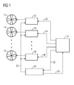
- FIG 1 illustrates a schematic block diagram of an apparatus for controlling and detecting the functions of a plurality of fans 12, 14 and 16 according to a preferred embodiment of the present invention.
- the apparatus includes a control unit 10, a driver and sensing device 20, a first fan driver 22, a second fan driver 24 and an Nth fan driver 26.
- the apparatus may be adapted for controlling and detecting the functions of two up to N fans 12, 14 and 16.
- the apparatus is connected to the fans 12, 14 and 16.
- the first fan driver 22 is connected via a unidirectional line to a first fan 12.
- the second fan driver 24 is connected via a unidirectional line to a second fan 14.
- an Nth fan driver 26 is connected via a unidirectional line to an Nth fan 16.
- the control unit 10 is connected to the N fan drivers 22, 24 and 26 via separate unidirectional lines. Further, the control unit 10 is connected to the driver and sensing device 20 via a unidirectional line. Contrary, the driver and sensing device 20 is connected to the control unit 10 via another unidirectional line. At last, the driver and sensing device 20 is connected to the N fan drivers 22, 24 and 26 via a common unidirectional line.
- a first pulse-width modulation signal 32 is sent from the control unit 10 to the first fan driver 22.
- a second pulse-width modulation signal 34 is sent from the control unit 10 to the second fan driver 24.
- an Nth pulse-width modulation signal is sent from the control unit 10 to the Nth fan driver 26.
- a fan enabling signal 28 is sent from the control unit 10 to the driver and sensing device 20. Further, said fan enabling signal 28 is sent from the driver and sensing device 20 to the fan drivers 22, 24 and 26.
- a fan monitoring signal 30 is sent from the driver and sensing device 20 to the control unit 10.
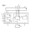
- FIG 2 illustrates a schematic block diagram of a system for controlling and detecting the functions of the plurality of fans 12, 14 and 16 according to the preferred embodiment of the present invention.
- the system comprises an input-output device 38, a fan speed monitoring device 40 and a sensing and control system 42.
- the sensing and control system 42 includes an analogue-digital converter system 44 and a fan control system 46.
- the input-output device 38 is realized by hardware, while the sensing and control system 42 is realized by software.
- the analogue-digital converter system 44 includes an analogue-digital converter 48 and averaging means 50.
- the fan control system 46 includes a fan control unit 52 and a look-up table 54.
- An analogue signal 56 is sent from the input-output device 38 to the analogue-digital converter 48.
- the analogue signal 56 corresponds with the speed of the fan 12, 14 or 16.
- the analogue-digital converter 48 samples and converts the analogue signal 56 into a sampled digital signal 58.
- the averaging means 50 averages the sampled digital signals 58 and generates a fan monitoring signal 60.
- the fan monitoring signal 60 is sent from the averaging means 50 of the analogue-digital converter system 44 to the fan control unit 52 of the fan control system 46.
- the fan control unit 52 generates the pulse-width modulation signals 32, 34 and 36 and the fan enabling signal 28 on the basis of the fan monitoring signal 60 from the averaging means 50 and one or more threshold values 64 provided by the look-up table 54.
- the fan speed monitoring device 40 may send a speed request 62 to the fan control unit 52, so that the current speed of the fans 12, 14 and 16 is indicated by said fan speed monitoring device 40.
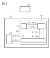
- FIG 3 illustrates a schematic flow chart diagram of an algorithm for detecting the functions of three fans 12, 14 and 16.
- the algorithm comprises an initial step 68 and a running mode 70.
- the running mode 70 includes the states of deactivated fans 72 and activated fans 74.
- the transition from the states of deactivated fans 72 to the states of activated fans 74 is performed, if the fan speed F_S is bigger than zero.
- the transition from the states of activated fans 74 back to the states of deactivated fans 72 occurs, if the fan speed F_S is zero.
- the state of activated fans 74 includes a normal operation mode 76, a dynamic fan checking routine 78 and a multiple-fan checking routine 80.
- the multiple-fan checking routine 80 is a three-fan checking routine.
- the normal operation mode 76 is obtained.
- the dynamic fan checking routine 78 is activated. If the fan monitoring signal F is smaller than a lock threshold value THR_L, then the algorithm changes from the dynamic fan checking routine 78 to the normal operation mode 76 again. However, if the fan monitoring signal F is bigger than the lock threshold value THR_L, then the algorithm changes from the dynamic fan checking routine 78 to the multiple-fan checking routine 80. If a fan timer signal FT exceeds a fourth fan timer threshold value THR3, then the algorithm changes from the multiple-fan checking routine 80 back to the dynamic fan checking routine 78.
- the three-fan checking routine 80 There are two ways for entering the three-fan checking routine 80.
- the first way is a periodic activation of the three-fan checking routine 80, wherein the three-fan checking routine 80 is activated periodically once a fault has been detected. For example, every four minutes a reactivation attempt and a check of all fans 12, 14 and 16 is performed.
- the second way is a conditional activation of the three-fan checking routine 80, wherein the pulse-width modulation signals 32, 34 and 36 are fixed at 100%. If a fault is detected, then the three-fan checking routine 80 is immediately triggered. During the running mode 70 the three-fan checking routine 80 is possible, if at least one fan 12, 14 or 16 is locked. In this example, the three-fan checking routine 80 requires 41 seconds.
- the dynamic fan check routine 78 is called periodically. In this example, the dynamic fan check routine 78 is called every 100 milliseconds. A predetermined number of sampled digital signals 58 from the analogue-digital converter are averaged. In this example, thirty sampled digital signals 58 are averaged, so that every three seconds a dynamic fan lock evaluation is performed.
- the pulse-width modulation signals 32, 34 and 36 of the fans 12, 14 and 16 are constantly at 100%. There are conditions, in which a locked fan 12, 14 or 16 may be detected. If all fans 12, 14 and 16 are enabled, i.e. no fan 12, 14 or 16 is disabled by the three-fan checking routine 80, then a three-fan threshold value D3_THR is used to detect that at least one of the fans 12, 14 and 16 is locked. If at least one fan 12, 14 and/or 16 is disabled by the three-fan checking routine 80, then a two-fan threshold value D2_THR is used to detect that at least one of the fans 12, 14 and 16 is locked.
- FIG 4 illustrates a schematic flow chart diagram of the multiple-fan checking routine 80 according to the preferred embodiment of the present invention.
- the multiple-fan checking routine is the three-fan checking routine 80.
- the three-fan checking routine 80 comprises an initial step 82, a first fan test 84, a second fan test 86, a third fan test 88 and a final step 90.
- the initialization of all variables of the algorithm is executed.
- the fan timer signal FT exceeds a first fan timer threshold value THR0
- the first fan test 84 is activated.
- the second fan test 86 is activated.
- the fan timer signal FT exceeds a third fan timer threshold value THR2
- the third fan test 88 is activated.
- the final step 90 is activated.
- the first fan test 84 only the first fan 12 is enabled for a predetermined time. In this example, the first fan 12 is enabled for 13 seconds. Further, the fan speed is set at a predetermined level, in this example at 60%. From the 9th to the 12th seconds the analogue signal 56 is sampled in order to stabilize the speed of the first fan 12.
- only the second fan 14 is enabled during the second fan test 86 for 13 seconds and the fan speed is set at 60%. From the 9th to the 12th seconds the analogue signal 56 is sampled in order to stabilize the speed of the second fan 14. In a uniform manner, only the third fan 14 is enabled during the third fan test 88 for 13 seconds and the fan speed is set at 60%. From the 9th to the 12th seconds the analogue signal 56 is sampled in order to stabilize the speed of the third fan 16.
- each fan test 84, 86 and 88 thirty samples of the analogue signal 56 are acquired from the 9th to the 12th seconds and averaged, so that the fan monitoring signal 60 is obtained. Then the fan monitoring signal 60 is compared with the lock threshold value THR_L and a disconnecting threshold value THR_D.
- the total number of locked and/or disconnected fans 12, 14 and 16 is calculated. Each locked and/or disconnected fan 12, 14 and 16 is disabled until the next activation of the three-fan check routine 80. For example, the next three-fan check routine 80 is activated after four minutes. At last, the final step finishes the three-fan checking routine 80.
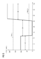
- FIG 5 illustrates a schematic diagram of the fan monitoring signal F as function of the time t during the multiple-fan checking routine 80 according to the preferred embodiment of the present invention.
- the multiple-fan checking routine is the three-fan checking routine 80.
- the fan monitoring signal F is represented as an eight-bit value.
- the disconnecting threshold value THR_D is 30.
- the lock threshold value THR_L is 168.
- the fan monitoring signal F has a value of about 100, wherein the fan monitoring signal F is between the disconnecting threshold value THR_D and the lock threshold value THR_L.
- the fan monitoring signal F has a value of slightly more than zero, wherein the fan monitoring signal F is smaller than the disconnecting threshold value THR_D.
- the fan monitoring signal F has a value of about 220, wherein the fan monitoring signal F is bigger than the lock threshold value THR_L.
- the multiple-fan checking routine 80 causes a delay of about 240 seconds.
- the algorithm of the present invention has the advantage that the multiple-fan checking routine 80 is not necessary, if during the dynamic fan checking routine 78 the fan monitoring signal F is smaller than the lock threshold value THR_L.
- the maximum time for deactivating the locked fan 12, 14 and/or 16 is about 41 seconds. This results in a low heating of the windings of the fan 12, 14 and/or 16.
- the algorithm of the present invention is suitable for two up to N fans.
Landscapes
- Engineering & Computer Science (AREA)
- Mechanical Engineering (AREA)
- General Engineering & Computer Science (AREA)
- Chemical & Material Sciences (AREA)
- Combustion & Propulsion (AREA)
- Physics & Mathematics (AREA)
- Signal Processing (AREA)
- Fluid Mechanics (AREA)
- Fuzzy Systems (AREA)
- Mathematical Physics (AREA)
- Control Of Positive-Displacement Air Blowers (AREA)
Abstract
Description
- The present invention relates to a method for checking the functions of fans within an ensemble of a plurality of fans. Further, the present invention relates to an apparatus for controlling and detecting the functions of fans within an ensemble of a plurality of fans. Moreover, the present invention relates to a domestic appliance with an ensemble of a plurality of fans. Additionally, the present invention relates to a computer program stored in a computer usable medium, comprising computer readable program means for causing a computer to perform a method for checking the functions of fans within an ensemble of a plurality of fans.
- Fans for cooling and venting purposes are used in different types of appliances. For example, a cooking hob, a cooking oven and a hood may comprise one or more fans. In some cases, safety standards require the detection of faults on the fans. In particular, a lock or disconnection of the fan may occur. It is desired that the detection of faults on the fans does not significantly disturb the operation of the fans.
- It is an object of the present invention to provide a method for checking the functions of fans within an ensemble of a plurality of fans, wherein the time of deactivating the fans is minimized.
- The object is achieved by the method according to claim 1.
- According to the present invention the method for checking the functions of fans within an ensemble of a plurality of fans, said method comprises the following steps:
- starting a normal operation mode,
- detecting or evaluating a common fan monitoring signal depending on the speeds of the fans,
- starting a dynamic fan checking routine, in which the fan monitoring signal is compared with a lock threshold value,
- if the fan monitoring signal is smaller than the lock threshold value, then the dynamic fan checking routine is finished and the normal operation mode is set forth,
- if the fan monitoring signal is bigger than the lock threshold value, then the dynamic fan checking routine is finished and a multiple-fan checking routine is started, and
- consecutive fan tests corresponding with one single fan in each case are performed during the multiple-fan checking routine, wherein
- during each fan test the corresponding fan is activated for a predetermined time period, while the other fans are deactivated during said time period,
- during each fan test the fan monitoring signal is compared with the lock threshold value and a disconnecting threshold value,
- if the fan monitoring signal is bigger than the lock threshold value, then the corresponding fan is locked and an error is detected, and
- if the fan monitoring signal is smaller than the disconnecting threshold value, then the corresponding fan is disconnected and an error is detected.
- The core of the present invention is the combination of the dynamic fan checking routine and the subsequent possible multiple-fan checking routine. If no locked fan is detected during the dynamic fan checking routine, then the multiple-fan checking routine is not necessary.
- Preferably, the speed of each fan is controlled by a corresponding pulse-width modulation signal, while the fans are enabled and disabled by a common fan enabling signal.
- For example, the predetermined time period for the fan test is between ten and twenty seconds, preferably thirteen seconds.
- In particular, the fan monitoring signal bases on an analogue signal, preferably on a current signal amplitude of the fans, sampled and averaged by an analogue-digital converter system.
- In this case, the samples of the analogue signal are taken during the last part of the predetermined time period of the fan test, in particular during the last third of the predetermined time period, preferably during the 9th to the 12th seconds of the time period of thirteen seconds.
- For example, between 20 and 50 samples, preferably 30 samples, of the fan monitoring signal are taken within the last part of the predetermined time period of the fan test.
- Further, the lock threshold value may be adapted or adaptable to the number of enabled and disabled fans during the dynamic fan checking routine.
- Moreover, during the dynamic fan checking routine between 20 and 50 samples, preferably 30 samples, of the fan monitoring signal may be taken within a time period of between two seconds and five second, preferably three seconds.
- Preferably, during the dynamic fan checking routine the speed of the fan is at its maximum value.
- In contrast, during the fan test, the speed of the fan may be between 40% and 80% of its maximum value, preferably 60% of its maximum value.
- In particular, the fan monitoring signal is represented by a binary coded number, preferably by an eight-bit number.
- For example, the multiple-fan checking routine is periodically activated after a predetermined time interval once an error has been detected, wherein said time interval is between three and five minutes, preferably four minutes.
- Alternatively, the multiple-fan checking routine is immediately activated, if an error has been detected.
- Further, the present invention relates to an apparatus for controlling and detecting the functions of fans within an ensemble of a plurality of fans, wherein the apparatus is provided for a method mentioned above.
- Additionally, the present invention relates to a domestic appliance with an ensemble of a plurality of fans, wherein the domestic appliance comprises the apparatus for controlling and detecting the functions of fans and/or the domestic appliance is provided for the method mentioned above.
- At last, the present invention relates to a computer program stored in a computer usable medium, comprising computer readable program means for causing a computer to perform the method described above.
- Novel and inventive features of the present invention are set forth in the appended claims.
- The present invention will be described in further detail with reference to the drawing, in which
- FIG 1
- illustrates a schematic block diagram of an apparatus for controlling and detecting the functions of a plurality of fans according to a preferred embodiment of the present invention,
- FIG 2
- illustrates a schematic block diagram of a system for controlling and detecting the functions of a plurality of fans according to the preferred embodiment of the present invention,
- FIG 3
- illustrates a schematic flow chart diagram of an algorithm for detecting the functions of a plurality of fans according to the preferred embodiment of the present invention,
- FIG 4
- illustrates a schematic flow chart diagram of a multiple-fan checking routine according to the preferred embodiment of the present invention, and
- FIG 5
- illustrates a schematic diagram of a fan monitoring signal as function of the time t during the multiple-fan checking routine according to the preferred embodiment of the present invention.
-
FIG 1 illustrates a schematic block diagram of an apparatus for controlling and detecting the functions of a plurality offans control unit 10, a driver andsensing device 20, afirst fan driver 22, asecond fan driver 24 and an Nthfan driver 26. The apparatus may be adapted for controlling and detecting the functions of two up toN fans fans - The
first fan driver 22 is connected via a unidirectional line to afirst fan 12. In a similar way, thesecond fan driver 24 is connected via a unidirectional line to asecond fan 14. Moreover, an Nthfan driver 26 is connected via a unidirectional line to anNth fan 16. Thecontrol unit 10 is connected to theN fan drivers control unit 10 is connected to the driver andsensing device 20 via a unidirectional line. Contrary, the driver andsensing device 20 is connected to thecontrol unit 10 via another unidirectional line. At last, the driver andsensing device 20 is connected to theN fan drivers - A first pulse-
width modulation signal 32 is sent from thecontrol unit 10 to thefirst fan driver 22. In a similar way, a second pulse-width modulation signal 34 is sent from thecontrol unit 10 to thesecond fan driver 24. Moreover, an Nth pulse-width modulation signal is sent from thecontrol unit 10 to theNth fan driver 26. Afan enabling signal 28 is sent from thecontrol unit 10 to the driver andsensing device 20. Further, saidfan enabling signal 28 is sent from the driver andsensing device 20 to thefan drivers fan monitoring signal 30 is sent from the driver andsensing device 20 to thecontrol unit 10. -
FIG 2 illustrates a schematic block diagram of a system for controlling and detecting the functions of the plurality offans output device 38, a fan speed monitoring device 40 and a sensing andcontrol system 42. The sensing andcontrol system 42 includes an analogue-digital converter system 44 and afan control system 46. In this example, the input-output device 38 is realized by hardware, while the sensing andcontrol system 42 is realized by software. The analogue-digital converter system 44 includes an analogue-digital converter 48 and averaging means 50. Thefan control system 46 includes afan control unit 52 and a look-up table 54. - An
analogue signal 56 is sent from the input-output device 38 to the analogue-digital converter 48. Theanalogue signal 56 corresponds with the speed of thefan digital converter 48 samples and converts theanalogue signal 56 into a sampleddigital signal 58. The averaging means 50 averages the sampleddigital signals 58 and generates afan monitoring signal 60. Thefan monitoring signal 60 is sent from the averaging means 50 of the analogue-digital converter system 44 to thefan control unit 52 of thefan control system 46. - The
fan control unit 52 generates the pulse-width modulation signals 32, 34 and 36 and thefan enabling signal 28 on the basis of thefan monitoring signal 60 from the averaging means 50 and one or more threshold values 64 provided by the look-up table 54. - The fan speed monitoring device 40 may send a
speed request 62 to thefan control unit 52, so that the current speed of thefans -
FIG 3 illustrates a schematic flow chart diagram of an algorithm for detecting the functions of threefans initial step 68 and a runningmode 70. The runningmode 70 includes the states of deactivatedfans 72 and activatedfans 74. The transition from the states of deactivatedfans 72 to the states of activatedfans 74 is performed, if the fan speed F_S is bigger than zero. In contrast, the transition from the states of activatedfans 74 back to the states of deactivatedfans 72 occurs, if the fan speed F_S is zero. Further, the state of activatedfans 74 includes anormal operation mode 76, a dynamicfan checking routine 78 and a multiple-fan checking routine 80. In this example, the multiple-fan checking routine 80 is a three-fan checking routine. - When the
fans normal operation mode 76 is obtained. When the number of samples N_S exceeds a threshold value of samples THR_S sufficient for averaging the monitoring signal F, then the dynamicfan checking routine 78 is activated. If the fan monitoring signal F is smaller than a lock threshold value THR_L, then the algorithm changes from the dynamic fan checking routine 78 to thenormal operation mode 76 again. However, if the fan monitoring signal F is bigger than the lock threshold value THR_L, then the algorithm changes from the dynamic fan checking routine 78 to the multiple-fan checking routine 80. If a fan timer signal FT exceeds a fourth fan timer threshold value THR3, then the algorithm changes from the multiple-fan checking routine 80 back to the dynamicfan checking routine 78. - There are two ways for entering the three-
fan checking routine 80. The first way is a periodic activation of the three-fan checking routine 80, wherein the three-fan checking routine 80 is activated periodically once a fault has been detected. For example, every four minutes a reactivation attempt and a check of allfans fan checking routine 80, wherein the pulse-width modulation signals 32, 34 and 36 are fixed at 100%. If a fault is detected, then the three-fan checking routine 80 is immediately triggered. During the runningmode 70 the three-fan checking routine 80 is possible, if at least onefan fan checking routine 80 requires 41 seconds. - The dynamic
fan check routine 78 is called periodically. In this example, the dynamicfan check routine 78 is called every 100 milliseconds. A predetermined number of sampleddigital signals 58 from the analogue-digital converter are averaged. In this example, thirty sampleddigital signals 58 are averaged, so that every three seconds a dynamic fan lock evaluation is performed. - During the dynamic
fan check routine 78 the pulse-width modulation signals 32, 34 and 36 of thefans fan fans fan fan checking routine 80, then a three-fan threshold value D3_THR is used to detect that at least one of thefans fan fan checking routine 80, then a two-fan threshold value D2_THR is used to detect that at least one of thefans -
FIG 4 illustrates a schematic flow chart diagram of the multiple-fan checking routine 80 according to the preferred embodiment of the present invention. In this example, the multiple-fan checking routine is the three-fan checking routine 80. The three-fan checking routine 80 comprises aninitial step 82, afirst fan test 84, asecond fan test 86, athird fan test 88 and afinal step 90. - In the
initial step 82 the initialization of all variables of the algorithm is executed. When the fan timer signal FT exceeds a first fan timer threshold value THR0, then thefirst fan test 84 is activated. In a similar way, when the fan timer signal FT exceeds a second fan timer threshold value THR1, thesecond fan test 86 is activated. Moreover, when the fan timer signal FT exceeds a third fan timer threshold value THR2, then thethird fan test 88 is activated. At last, when the fan timer signal FT exceeds the fourth fan timer threshold value THR3, thefinal step 90 is activated. - During the
first fan test 84 only thefirst fan 12 is enabled for a predetermined time. In this example, thefirst fan 12 is enabled for 13 seconds. Further, the fan speed is set at a predetermined level, in this example at 60%. From the 9th to the 12th seconds theanalogue signal 56 is sampled in order to stabilize the speed of thefirst fan 12. - In a similar way, only the
second fan 14 is enabled during thesecond fan test 86 for 13 seconds and the fan speed is set at 60%. From the 9th to the 12th seconds theanalogue signal 56 is sampled in order to stabilize the speed of thesecond fan 14. In a uniform manner, only thethird fan 14 is enabled during thethird fan test 88 for 13 seconds and the fan speed is set at 60%. From the 9th to the 12th seconds theanalogue signal 56 is sampled in order to stabilize the speed of thethird fan 16. - In each
fan test analogue signal 56 are acquired from the 9th to the 12th seconds and averaged, so that thefan monitoring signal 60 is obtained. Then thefan monitoring signal 60 is compared with the lock threshold value THR_L and a disconnecting threshold value THR_D. - If the
fan monitoring signal 60 is above the lock threshold value THR_L, then the activatedfan fan monitoring signal 60 is below the disconnecting threshold value THR_D, then the activatedfan - During the
final step 90 the total number of locked and/or disconnectedfans fan fan check routine 80. For example, the next three-fan check routine 80 is activated after four minutes. At last, the final step finishes the three-fan checking routine 80. -
FIG 5 illustrates a schematic diagram of the fan monitoring signal F as function of the time t during the multiple-fan checking routine 80 according to the preferred embodiment of the present invention. In this example, the multiple-fan checking routine is the three-fan checking routine 80. - The fan monitoring signal F is represented as an eight-bit value. The disconnecting threshold value THR_D is 30. The lock threshold value THR_L is 168. During a
first phase 92 of about thirteen seconds the fan monitoring signal F has a value of about 100, wherein the fan monitoring signal F is between the disconnecting threshold value THR_D and the lock threshold value THR_L. During a second phase 94 of about further thirteen seconds the fan monitoring signal F has a value of slightly more than zero, wherein the fan monitoring signal F is smaller than the disconnecting threshold value THR_D. During athird phase 96 of about further thirteen seconds the fan monitoring signal F has a value of about 220, wherein the fan monitoring signal F is bigger than the lock threshold value THR_L. - During the
first phase 92 thefirst fan 12 is running normally. The fan monitoring signal F during the second phase 94 indicates that thesecond fan 14 is disconnected. The fan monitoring signal F during thethird phase 96 indicates that thethird fan 16 is locked. As result thesecond fan 14 and thethird fan 16 are disabled. The multiple-fan checking routine 80 causes a delay of about 240 seconds. - The algorithm of the present invention has the advantage that the multiple-
fan checking routine 80 is not necessary, if during the dynamic fan checking routine 78 the fan monitoring signal F is smaller than the lock threshold value THR_L. In this example, the maximum time for deactivating the lockedfan fan - Although an illustrative embodiment of the present invention has been described herein with reference to the accompanying drawing, it is to be understood that the present invention is not limited to that precise embodiment, and that various other changes and modifications may be affected therein by one skilled in the art without departing from the scope or spirit of the invention. All such changes and modifications are intended to be included within the scope of the invention as defined by the appended claims.
-
- 10
- control unit
- 12
- first fan
- 14
- second fan
- 16
- Nth fan
- 20
- driver and sensing device
- 22
- first fan driver
- 24
- second fan driver
- 26
- Nth fan driver
- 28
- fan enabling signal
- 30
- fan monitoring signal
- 32
- first pulse-width modulation signal
- 34
- second pulse-width modulation signal
- 36
- Nth pulse-width modulation signal
- 38
- input-output device
- 40
- fan speed monitoring device
- 42
- sensing and control system
- 44
- analogue-digital converter system
- 46
- fan control system
- 48
- analogue-digital converter
- 50
- averaging means
- 52
- fan control unit
- 54
- look-up table
- 56
- analogue signal
- 58
- sampled digital signal
- 60
- fan monitoring signal
- 62
- speed request
- 64
- threshold value
- 68
- initial step
- 70
- running mode
- 72
- state of deactivated fans
- 74
- state of activated fans
- 76
- normal operation mode
- 78
- dynamic fan checking routine
- 80
- multiple-fan checking routine, three-fan checking routine
- 82
- initial step
- 84
- first fan test
- 86
- second fan test
- 88
- third fan test
- 90
- final step
- 92
- first phase
- 94
- second phase
- 96
- third phase
- F
- fan monitoring signal
- FT
- fan timer signal
- F_S
- fan speed
- THR0
- first fan timer threshold value
- THR1
- second fan timer threshold value
- THR2
- third fan timer threshold value
- THR3
- fourth fan timer threshold value
- D2_THR
- two-fan threshold value
- D3_THR
- three-fan threshold value
- N_S
- number of samples
- THR_S
- threshold value of samples
- THR_L
- lock threshold value
- THR_D
- disconnecting threshold value
- t
- time
Claims (15)
- A method for checking the functions of fans (12, 14, 16) within an ensemble of a plurality of fans (12, 14, 16), said method comprises the following steps:- starting a normal operation mode (76),- detecting or evaluating a common fan monitoring signal (F) depending on the speeds of the fans (12, 14, 16),- starting a dynamic fan checking routine (78), in which the fan monitoring signal (F) is compared with a lock threshold value (THR_L; D2_THR, D3_THR),- if the fan monitoring signal (F) is smaller than the lock threshold value (THR_L; D2_THR, D3_THR), then the dynamic fan checking routine (78) is finished and the normal operation mode (76) is set forth,- if the fan monitoring signal (F) is bigger than the lock threshold value (THR_L; D2_THR, D3_THR), then the dynamic fan checking routine (78) is finished and a multiple-fan checking routine (80) is started, and- consecutive fan tests (84, 86, 88) corresponding with one single fan (12, 14, 16) in each case are performed during the multiple-fan checking routine (80), wherein- during each fan test (84, 86, 88) the corresponding fan (12, 14, 16) is activated for a predetermined time period, while the other fans (84, 86, 88) are deactivated during said time period,- during each fan test (84, 86, 88) the fan monitoring signal (F) is compared with the lock threshold value (THR_L) and a disconnecting threshold value (THR_D),- if the fan monitoring signal (F) is bigger than the lock threshold value (THR_L), then the corresponding fan (12, 14, 16) is locked and an error is detected, and- if the fan monitoring signal (F) is smaller than the disconnecting threshold value (THR_D), then the corresponding fan (12, 14, 16) is disconnected and an error is detected.
- The method according to claim 1,
characterized in that
the speed of each fan (12, 14, 16) is controlled by a corresponding pulse-width modulation signal (32, 34, 36), while the fans (12, 14, 16) are enabled and disabled by a common fan enabling signal (28). - The method according to claim 1 or 2,
characterized in that
the predetermined time period for the fan test (84, 86, 88) is between ten and twenty seconds, preferably thirteen seconds. - The method according to any one of the preceding claims,
characterized in that
the fan monitoring signal (F) bases on an analogue signal (56), preferably a current signal amplitude of the fans (12, 14, 16), sampled and averaged by an analogue-digital converter system (44). - The method according to claim 4,
characterized in that
samples of the analogue signal (56) are taken during the last part of the predetermined time period of the fan test (84, 86, 88), in particular during the last third of the predetermined time period, preferably during the 9th to the 12th seconds of the time period of thirteen seconds. - The method according to claim 5,
characterized in that
between 20 and 50 samples, preferably 30 samples, of the fan monitoring signal (F) are taken within the last part of the predetermined time period of the fan test (84, 86, 88). - The method according to any one of the preceding claims,
characterized in that
the lock threshold value (D2_THR, D3_THR) is adapted or adaptable to the number of enabled and disabled fans (12, 14, 16) during the dynamic fan checking routine (78). - The method according to any one of the preceding claims,
characterized in that
during the dynamic fan checking routine (78) between 20 and 50 samples, preferably 30 samples, of the fan monitoring signal (F) are taken within a time period of between two seconds and five second, preferably three seconds. - The method according to any one of the preceding claims,
characterized in that
during the dynamic fan checking routine (78) the speed of the fan (12, 14, 16) is at its maximum value. - The method according to any one of the preceding claims,
characterized in that
during the fan test (84, 86, 88) the speed of the fan (12, 14, 16) is between 40% and 80% of its maximum value, preferably 60% of its maximum value. - The method according to any one of the preceding claims,
characterized in that
the fan monitoring signal (F) is represented by a binary coded number, preferably by an eight-bit number. - The method according to any one of the preceding claims,
characterized in that
either the multiple-fan checking routine (80) is periodically activated after a predetermined time interval once an error has been detected, wherein said time interval is between three and five minutes, preferably four minutes, or the multiple-fan checking routine (80) is immediately activated, if an error has been detected. - An apparatus for controlling and detecting the functions of fans (12, 14, 16) within an ensemble of a plurality of fans (12, 14, 16),
characterized in that
the apparatus is provided for a method according to any one of the claims 1 to 12. - A domestic appliance with an ensemble of a plurality of fans (12, 14, 16),
characterized in that
the domestic appliance comprises an apparatus for controlling and detecting the functions of fans (12, 14, 16) according to claim 13 and/or the domestic appliance is provided for a method according to any one of the claims 1 to 12. - A computer program stored in a computer usable medium, comprising computer readable program means for causing a computer to perform a method according to any one of the claims 1 to 12.
Priority Applications (6)
| Application Number | Priority Date | Filing Date | Title |
|---|---|---|---|
| EP15154601.7A EP3056829A1 (en) | 2015-02-11 | 2015-02-11 | Method for checking the functions of a plurality of fans |
| US15/534,224 US10584708B2 (en) | 2015-02-11 | 2016-02-01 | Method for checking the functions of a plurality of fans |
| AU2016218154A AU2016218154A1 (en) | 2015-02-11 | 2016-02-01 | Method for checking the functions of a plurality of fans |
| PCT/EP2016/052024 WO2016128236A1 (en) | 2015-02-11 | 2016-02-01 | Method for checking the functions of a plurality of fans |
| CN201680009533.3A CN107208916B (en) | 2015-02-11 | 2016-02-01 | Method for checking the function of a plurality of fans |
| BR112017016412A BR112017016412A2 (en) | 2015-02-11 | 2016-02-01 | method for verifying fan functions, apparatus for controlling and detecting fan functions, appliance and computer program |
Applications Claiming Priority (1)
| Application Number | Priority Date | Filing Date | Title |
|---|---|---|---|
| EP15154601.7A EP3056829A1 (en) | 2015-02-11 | 2015-02-11 | Method for checking the functions of a plurality of fans |
Publications (1)
| Publication Number | Publication Date |
|---|---|
| EP3056829A1 true EP3056829A1 (en) | 2016-08-17 |
Family
ID=52468911
Family Applications (1)
| Application Number | Title | Priority Date | Filing Date |
|---|---|---|---|
| EP15154601.7A Withdrawn EP3056829A1 (en) | 2015-02-11 | 2015-02-11 | Method for checking the functions of a plurality of fans |
Country Status (6)
| Country | Link |
|---|---|
| US (1) | US10584708B2 (en) |
| EP (1) | EP3056829A1 (en) |
| CN (1) | CN107208916B (en) |
| AU (1) | AU2016218154A1 (en) |
| BR (1) | BR112017016412A2 (en) |
| WO (1) | WO2016128236A1 (en) |
Cited By (2)
| Publication number | Priority date | Publication date | Assignee | Title |
|---|---|---|---|---|
| CN115492785A (en) * | 2022-09-15 | 2022-12-20 | 华能国际电力股份有限公司上安电厂 | An oxidation fan control system and optimization method |
| CN115949610A (en) * | 2023-02-07 | 2023-04-11 | 中煤科工集团重庆研究院有限公司 | A method to prevent the false alarm of the main ventilator in the mine when it is on or off |
Families Citing this family (2)
| Publication number | Priority date | Publication date | Assignee | Title |
|---|---|---|---|---|
| US11229142B2 (en) * | 2020-06-10 | 2022-01-18 | Asia Vital Components Co., Ltd. | Fan control system |
| CN114658681B (en) * | 2022-04-15 | 2024-10-29 | 长虹美菱股份有限公司 | A method for detecting refrigerator fan |
Citations (6)
| Publication number | Priority date | Publication date | Assignee | Title |
|---|---|---|---|---|
| US6386969B1 (en) * | 2001-09-21 | 2002-05-14 | O'brien Robert D. | Garage ventilation system |
| US20040130868A1 (en) * | 2003-01-08 | 2004-07-08 | Schwartz William H. | Cooling system including redundant fan controllers |
| CN2793626Y (en) * | 2005-01-06 | 2006-07-05 | 亚翔工程股份有限公司 | Fan-filter unit matrix addressing monitoring structure |
| US20060168975A1 (en) * | 2005-01-28 | 2006-08-03 | Hewlett-Packard Development Company, L.P. | Thermal and power management apparatus |
| US20110070098A1 (en) * | 2009-09-18 | 2011-03-24 | Sunonwealth Electric Machine Industry Co., Ltd. | Fan control system |
| CN104135838A (en) * | 2014-07-21 | 2014-11-05 | 浪潮电子信息产业股份有限公司 | Centralized management method for heat dissipation of high-density cabinet |
Family Cites Families (8)
| Publication number | Priority date | Publication date | Assignee | Title |
|---|---|---|---|---|
| US5675480A (en) * | 1996-05-29 | 1997-10-07 | Compaq Computer Corporation | Microprocessor control of parallel power supply systems |
| JP2001193687A (en) * | 2000-01-12 | 2001-07-17 | Nec Eng Ltd | Faulty fan detection device |
| JP2003101274A (en) * | 2001-09-19 | 2003-04-04 | Fujitsu Ltd | Equipment with blower unit |
| JP2004257668A (en) * | 2003-02-26 | 2004-09-16 | Kyocera Corp | Ventilation equipment |
| US20070081888A1 (en) * | 2003-11-18 | 2007-04-12 | Howard Harrison | Series fans with flow modification element |
| CN1959255A (en) * | 2005-11-03 | 2007-05-09 | 乐金电子(天津)电器有限公司 | Method for sensing if fan of air conditioner is locked |
| CN102208892B (en) * | 2010-03-25 | 2016-02-17 | 罗姆股份有限公司 | Motor-drive circuit, cooling device, electronic equipment, timely checking circuit |
| CN103939374B (en) * | 2014-04-23 | 2016-03-02 | 凯迈(洛阳)机电有限公司 | One has brush electronic fan to drive protective system and self-diagnosing method |
-
2015
- 2015-02-11 EP EP15154601.7A patent/EP3056829A1/en not_active Withdrawn
-
2016
- 2016-02-01 US US15/534,224 patent/US10584708B2/en not_active Expired - Fee Related
- 2016-02-01 CN CN201680009533.3A patent/CN107208916B/en not_active Expired - Fee Related
- 2016-02-01 WO PCT/EP2016/052024 patent/WO2016128236A1/en not_active Ceased
- 2016-02-01 AU AU2016218154A patent/AU2016218154A1/en not_active Abandoned
- 2016-02-01 BR BR112017016412A patent/BR112017016412A2/en not_active Application Discontinuation
Patent Citations (6)
| Publication number | Priority date | Publication date | Assignee | Title |
|---|---|---|---|---|
| US6386969B1 (en) * | 2001-09-21 | 2002-05-14 | O'brien Robert D. | Garage ventilation system |
| US20040130868A1 (en) * | 2003-01-08 | 2004-07-08 | Schwartz William H. | Cooling system including redundant fan controllers |
| CN2793626Y (en) * | 2005-01-06 | 2006-07-05 | 亚翔工程股份有限公司 | Fan-filter unit matrix addressing monitoring structure |
| US20060168975A1 (en) * | 2005-01-28 | 2006-08-03 | Hewlett-Packard Development Company, L.P. | Thermal and power management apparatus |
| US20110070098A1 (en) * | 2009-09-18 | 2011-03-24 | Sunonwealth Electric Machine Industry Co., Ltd. | Fan control system |
| CN104135838A (en) * | 2014-07-21 | 2014-11-05 | 浪潮电子信息产业股份有限公司 | Centralized management method for heat dissipation of high-density cabinet |
Cited By (2)
| Publication number | Priority date | Publication date | Assignee | Title |
|---|---|---|---|---|
| CN115492785A (en) * | 2022-09-15 | 2022-12-20 | 华能国际电力股份有限公司上安电厂 | An oxidation fan control system and optimization method |
| CN115949610A (en) * | 2023-02-07 | 2023-04-11 | 中煤科工集团重庆研究院有限公司 | A method to prevent the false alarm of the main ventilator in the mine when it is on or off |
Also Published As
| Publication number | Publication date |
|---|---|
| BR112017016412A2 (en) | 2018-03-27 |
| WO2016128236A1 (en) | 2016-08-18 |
| US10584708B2 (en) | 2020-03-10 |
| US20180258942A1 (en) | 2018-09-13 |
| CN107208916A (en) | 2017-09-26 |
| AU2016218154A1 (en) | 2017-06-29 |
| CN107208916B (en) | 2020-03-06 |
Similar Documents
| Publication | Publication Date | Title |
|---|---|---|
| US20180258942A1 (en) | Method For Checking The Functions Of A Plurality Of Fans | |
| US8970203B2 (en) | Field device for process automation | |
| US10222075B2 (en) | Air-conditioning system and transmission relaying apparatus thereof | |
| US20180064280A1 (en) | Control of the heating of a household appliance via virtual temperature | |
| US20140100709A1 (en) | Electronic system, electronic system control method, and recording medium | |
| CN113007121B (en) | System and method for detecting performance degradation of a control valve | |
| AU2017226399A1 (en) | Synchronous control method and synchronous control system of multiple controlled components | |
| US9600357B2 (en) | Error detection method of failsafe software | |
| US10267416B2 (en) | Control apparatus | |
| US7424641B2 (en) | Control system and method for validating operation of the control system | |
| JP2015152598A (en) | Method and apparatus for recognizing a short circuit in a PWM driver circuit | |
| CN108333981B (en) | Compressor stop control method and device | |
| US12287626B2 (en) | Device and method for the control of safety apparatuses | |
| JP6824711B2 (en) | Electronic control device | |
| AU2019398265B2 (en) | Method for performing a drying function after a cooking function or steam cooking function | |
| CN115903525B (en) | Relay control method and system, and smart home appliance | |
| US20180219370A1 (en) | Power converter | |
| JP7390135B2 (en) | power converter | |
| KR101434435B1 (en) | Inverter DC Link Voltage Control System And Method Thereof | |
| JP7070206B2 (en) | In-vehicle control device | |
| KR20180090934A (en) | Power system and method of controlling | |
| CN110594177B (en) | Fan fault early warning method and device for power supply system | |
| EP1753119A2 (en) | Method and apparatus for detecting multiple overcurrent thresholds using a single comparator device | |
| CN119536220B (en) | A heating fault identification method, system, device and storage medium for aircraft windshield under half-power heating | |
| CN109611189B (en) | A diesel engine control system and method |
Legal Events
| Date | Code | Title | Description |
|---|---|---|---|
| PUAI | Public reference made under article 153(3) epc to a published international application that has entered the european phase |
Free format text: ORIGINAL CODE: 0009012 |
|
| AK | Designated contracting states |
Kind code of ref document: A1 Designated state(s): AL AT BE BG CH CY CZ DE DK EE ES FI FR GB GR HR HU IE IS IT LI LT LU LV MC MK MT NL NO PL PT RO RS SE SI SK SM TR |
|
| AX | Request for extension of the european patent |
Extension state: BA ME |
|
| STAA | Information on the status of an ep patent application or granted ep patent |
Free format text: STATUS: REQUEST FOR EXAMINATION WAS MADE |
|
| 17P | Request for examination filed |
Effective date: 20170217 |
|
| RBV | Designated contracting states (corrected) |
Designated state(s): AL AT BE BG CH CY CZ DE DK EE ES FI FR GB GR HR HU IE IS IT LI LT LU LV MC MK MT NL NO PL PT RO RS SE SI SK SM TR |
|
| GRAP | Despatch of communication of intention to grant a patent |
Free format text: ORIGINAL CODE: EPIDOSNIGR1 |
|
| STAA | Information on the status of an ep patent application or granted ep patent |
Free format text: STATUS: GRANT OF PATENT IS INTENDED |
|
| RIC1 | Information provided on ipc code assigned before grant |
Ipc: F04D 27/00 20060101ALI20200207BHEP Ipc: F24F 110/00 20180101ALI20200207BHEP Ipc: F04D 25/16 20060101ALI20200207BHEP Ipc: F24F 11/30 20180101ALI20200207BHEP Ipc: F24F 11/00 20180101AFI20200207BHEP |
|
| INTG | Intention to grant announced |
Effective date: 20200227 |
|
| GRAJ | Information related to disapproval of communication of intention to grant by the applicant or resumption of examination proceedings by the epo deleted |
Free format text: ORIGINAL CODE: EPIDOSDIGR1 |
|
| STAA | Information on the status of an ep patent application or granted ep patent |
Free format text: STATUS: REQUEST FOR EXAMINATION WAS MADE |
|
| GRAP | Despatch of communication of intention to grant a patent |
Free format text: ORIGINAL CODE: EPIDOSNIGR1 |
|
| STAA | Information on the status of an ep patent application or granted ep patent |
Free format text: STATUS: GRANT OF PATENT IS INTENDED |
|
| INTC | Intention to grant announced (deleted) | ||
| INTG | Intention to grant announced |
Effective date: 20200722 |
|
| STAA | Information on the status of an ep patent application or granted ep patent |
Free format text: STATUS: THE APPLICATION IS DEEMED TO BE WITHDRAWN |
|
| 18D | Application deemed to be withdrawn |
Effective date: 20201202 |