EP3056761A1 - Slotted cable retainer for lifting assembly and method of assembling - Google Patents
Slotted cable retainer for lifting assembly and method of assembling Download PDFInfo
- Publication number
- EP3056761A1 EP3056761A1 EP16154227.9A EP16154227A EP3056761A1 EP 3056761 A1 EP3056761 A1 EP 3056761A1 EP 16154227 A EP16154227 A EP 16154227A EP 3056761 A1 EP3056761 A1 EP 3056761A1
- Authority
- EP
- European Patent Office
- Prior art keywords
- cable
- retainer
- lifting assembly
- slot
- inner cavity
- Prior art date
- Legal status (The legal status is an assumption and is not a legal conclusion. Google has not performed a legal analysis and makes no representation as to the accuracy of the status listed.)
- Granted
Links
Images


Classifications
-
- F—MECHANICAL ENGINEERING; LIGHTING; HEATING; WEAPONS; BLASTING
- F16—ENGINEERING ELEMENTS AND UNITS; GENERAL MEASURES FOR PRODUCING AND MAINTAINING EFFECTIVE FUNCTIONING OF MACHINES OR INSTALLATIONS; THERMAL INSULATION IN GENERAL
- F16G—BELTS, CABLES, OR ROPES, PREDOMINANTLY USED FOR DRIVING PURPOSES; CHAINS; FITTINGS PREDOMINANTLY USED THEREFOR
- F16G11/00—Means for fastening cables or ropes to one another or to other objects; Caps or sleeves for fixing on cables or ropes
- F16G11/02—Means for fastening cables or ropes to one another or to other objects; Caps or sleeves for fixing on cables or ropes with parts deformable to grip the cable or cables; Fastening means which engage a sleeve or the like fixed on the cable
- F16G11/025—Fastening means which engage a sleeve or the like fixed on the cable, e.g. caps
-
- F—MECHANICAL ENGINEERING; LIGHTING; HEATING; WEAPONS; BLASTING
- F16—ENGINEERING ELEMENTS AND UNITS; GENERAL MEASURES FOR PRODUCING AND MAINTAINING EFFECTIVE FUNCTIONING OF MACHINES OR INSTALLATIONS; THERMAL INSULATION IN GENERAL
- F16G—BELTS, CABLES, OR ROPES, PREDOMINANTLY USED FOR DRIVING PURPOSES; CHAINS; FITTINGS PREDOMINANTLY USED THEREFOR
- F16G11/00—Means for fastening cables or ropes to one another or to other objects; Caps or sleeves for fixing on cables or ropes
- F16G11/10—Quick-acting fastenings; Clamps holding in one direction only
- F16G11/105—Clamps holding in one direction only
- F16G11/108—Clamps holding in one direction only using a ball or a cylinder
Definitions
- the embodiments herein relate to lifting assemblies and, more particularly, to a slotted cable retainer for such lifting assemblies, as well as a method of assembling a lifting assembly.
- Many lifting devices require attachment of a wire rope, such as a cable. This may be done by inserting a cable end fitting into a cable retainer, with the components being relatively dimensioned to prevent inadvertent removal of the cable end fitting during regular use.
- the loading on the lifting device is such that off-center forces may exist, thus requiring the cable end fitting to be a ball type fitting (i.e., spherical).
- the cable is required to be replaced on a regular basis, so attachment of the cable to the lifting device needs to support easy removal and replacement.
- the cable is relatively long (e.g., greater than 200 feet), so it is not practical to thread the entire length of the cable through the lifting device in order to achieve attachment.
- the cable needs to remain securely attached to the lifting device whether there are tension forces or forces in the opposite direction (i.e., compression).
- attachment of the cable is achieved through a retainer ring and a pair of split retainers all located in a cylindrical cavity.
- the split retainers are assembled to the cable end fitting and the retainer ring is positioned on the split retainers. This assembly is then inserted into the cavity of a housing.
- a human installation operator may find difficulty with assembly of the several components described above, particularly due to the split retainer arrangement that must sandwich the cable end fitting.
- the split retainers are pulled against the retainer ring and thus remain attached to the cable end fitting.
- a retaining device is added to prevent detachment of the cable from the lifting device during compressive forces of the cable since such forces may separate the split retainers that otherwise retain the cable end fitting.
- the retaining device is prone to incorrect installation due to the cumbersome assembly effort described above.
- a lifting assembly includes a cable end housing defining an inner cavity.
- the lifting assembly also includes a retainer ring disposed in the inner cavity at an end thereof.
- the lifting assembly further includes a cable retainer disposed in the inner cavity of the cable end housing and operative to retain a cable end fitting of a cable, the cable retainer extending from a first end to a second end and defining a slot extending from the first end to the second end to provide installation and removal access of the cable end fitting, the slot having a first slot portion and a second slot portion that are angularly oriented relative to each other.
- a method of assembling a lifting assembly includes disposing a retainer ring within an inner cavity defined by a cable end housing.
- the method also includes bending a cable to align the cable with a slot defined by a cable retainer, the slot having a first slot portion and a second slot portion that are angularly oriented relative to each other.
- the method further includes inserting the cable through the slot into the cable retainer.
- the method yet further includes pulling the cable to engage a cable end fitting of the cable into contact with an inner surface of the cable retainer.
- the method also includes placing the cable retainer and the cable end fitting within the inner cavity of the cable end housing and into contact with the retainer ring.
- FIGS. 1 and 2 a portion of a lifting assembly is illustrated and generally referenced with numeral 10.
- lifting assemblies Several types of lifting assemblies, systems or devices may benefit from the embodiments described herein.
- a crane, hoist or winch are exemplary embodiments of lifting assemblies that would particularly benefit from the embodiments of the invention described herein.
- the preceding list of examples is merely illustrative and it is to be understood that alternative lifting assemblies may incorporate the embodiments of the invention described herein.
- the lifting assembly 10 comprises a cable end housing 12 that defines an inner cavity 14 for housing components for retaining a cable end fitting 16, as will be appreciated from the description herein.
- the cable end housing 12 may be formed of several components that are operatively coupled to each other to form the overall housing ( FIG. 4 ). Additionally, certain components of the cable end housing 12 may be biased in desired manners with various biasing members, such as the springs illustrated in FIG. 4 .
- the inner cavity 14 defined by the cable end housing 12 at an interior region thereof. Although several alternative geometries of the inner cavity 14 are contemplated, an exemplary embodiment of the inner cavity 14 comprises a substantially cylindrical geometry.
- a cable 18 is shown to be disposed within the inner cavity 14 of the cable end housing 12.
- the cable end fitting 16 is disposed and retained within the cable end housing 12 to secure the cable to the portion of the lifting assembly 10.
- the cable end fitting 16 is typically formed of a substantially spherical geometry. Therefore, the cable end fitting 16 may be referred to as a ball type fitting. This geometry accommodates off-center forces that the cable 18 may exert on the lifting assembly 10 due to varied loading angles of loads applied to the cable 18.
- a retainer ring 20 defines an aperture 22 that is sized to fit over the cable end fitting 16 and is inserted into the inner cavity 14 of the cable end housing 12.
- the retainer ring 20 is inserted in a longitudinal direction of the cable end housing 12 to an end 24 of the inner cavity 14, as shown in FIG. 4 .
- a cable retainer 26 includes a first end 28 and a second end 30.
- a curvilinear wall 32 forms the cable retainer 26 and includes a retainer inner surface 34 and a retainer outer surface 36, with the retainer inner surface 34 defining an interior region 37 of the cable retainer 26.
- the cable retainer 26 also defines a slot 38 extending completely through the curvilinear wall 32 and completely from the first end 28 to the second end 30. More specifically, the slot 38 is defined by a first retainer wall 40 and a second retainer wall 42.
- the first and second retainer walls 40, 42 each include a first wall portion 46 and a second wall portion 48 that are angularly oriented relative to each other to define a geometric orientation of the slot 38 that is characterized as "chevron.” It is contemplated that only one of the first and second retainer walls have the angular oriented wall portions to form the chevron slot.
- a chevron orientation refers to a substantially zigzag length of the wall(s) to form a slot that does not extend along a single linear segment along its entire length.
- the slot 38 includes a first slot segment 50 and a second slot segment 52 that are angularly oriented relative to each other, such that the segments 50, 52 are not parallel.
- the cable retainer 26 is a single, integrally formed component in contrast to cable retainers having multi-piece designs, such as split collar designs, for example.
- the unitary cable retainer 26 allows an installation operator to easily grip the cable retainer 26 with one hand while inserting the cable 18 through the chevron slot 38 by bending the cable to align with the orientation of the chevron slot 38.
- the unitary cable retainer 26 may even facilitate one-handed installation of the cable 18 through the slot.
- the cable retainer Upon insertion through the slot 38, the cable retainer is inserted into the inner cavity 14 of the cable end housing 12. Insertion is made until the retainer outer surface 36 of the cable retainer 26 contacts a ring inner surface 44 of the retainer ring 20.
- the retainer outer surface 36 and the ring inner surface 44 have substantially corresponding geometries, such that the cable retainer 26 seats within a portion of the retainer ring 20 upon full insertion of the cable retainer 26 into the cable end housing 12. Typically, the cable retainer 26 and the retainer ring 20 are in direct contact. The cable 18 is then pulled to bring the cable end fitting 16 into contact with the retainer inner surface 34 of the cable retainer 26. Such a final assembled condition is shown in FIG. 4 .
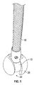
- the chevron slotted cable retainer 26 described herein has self-retaining capability to the cable end fitting 16, as shown in FIG. 5 . Additionally, installation and removal efforts are substantially simplified in comparison to a cable retainer having multiple components, such as a split collar design. In addition to enhancing the assembly process, a more reliable assembly is achieved with the embodiments of the cable retainer 26 described herein. Specifically, the cable fitting cannot be inadvertently removed from the cable retainer 26, even during a compressive force being applied to the cable 18. This is due to the single component that forms the cable retainer 26. In contrast, a split retainer may loosen during the imposition of a compressive force on the cable 18, thereby extracting the cable 18 and potentially leading to safety hazards.
Landscapes
- Engineering & Computer Science (AREA)
- General Engineering & Computer Science (AREA)
- Mechanical Engineering (AREA)
- Load-Engaging Elements For Cranes (AREA)
Abstract
Description
- The embodiments herein relate to lifting assemblies and, more particularly, to a slotted cable retainer for such lifting assemblies, as well as a method of assembling a lifting assembly.
- Many lifting devices require attachment of a wire rope, such as a cable. This may be done by inserting a cable end fitting into a cable retainer, with the components being relatively dimensioned to prevent inadvertent removal of the cable end fitting during regular use. The loading on the lifting device is such that off-center forces may exist, thus requiring the cable end fitting to be a ball type fitting (i.e., spherical). The cable is required to be replaced on a regular basis, so attachment of the cable to the lifting device needs to support easy removal and replacement. The cable is relatively long (e.g., greater than 200 feet), so it is not practical to thread the entire length of the cable through the lifting device in order to achieve attachment.
- The cable needs to remain securely attached to the lifting device whether there are tension forces or forces in the opposite direction (i.e., compression). Typically, attachment of the cable is achieved through a retainer ring and a pair of split retainers all located in a cylindrical cavity. The split retainers are assembled to the cable end fitting and the retainer ring is positioned on the split retainers. This assembly is then inserted into the cavity of a housing. However, it can be appreciated that a human installation operator may find difficulty with assembly of the several components described above, particularly due to the split retainer arrangement that must sandwich the cable end fitting.
- Providing tension on the cable is present, the split retainers are pulled against the retainer ring and thus remain attached to the cable end fitting. A retaining device is added to prevent detachment of the cable from the lifting device during compressive forces of the cable since such forces may separate the split retainers that otherwise retain the cable end fitting. Unfortunately, the retaining device is prone to incorrect installation due to the cumbersome assembly effort described above.
- According to one embodiment, a lifting assembly is provided. The lifting assembly includes a cable end housing defining an inner cavity. The lifting assembly also includes a retainer ring disposed in the inner cavity at an end thereof. The lifting assembly further includes a cable retainer disposed in the inner cavity of the cable end housing and operative to retain a cable end fitting of a cable, the cable retainer extending from a first end to a second end and defining a slot extending from the first end to the second end to provide installation and removal access of the cable end fitting, the slot having a first slot portion and a second slot portion that are angularly oriented relative to each other.
- According to another embodiment, a method of assembling a lifting assembly is provided. The method includes disposing a retainer ring within an inner cavity defined by a cable end housing. The method also includes bending a cable to align the cable with a slot defined by a cable retainer, the slot having a first slot portion and a second slot portion that are angularly oriented relative to each other. The method further includes inserting the cable through the slot into the cable retainer. The method yet further includes pulling the cable to engage a cable end fitting of the cable into contact with an inner surface of the cable retainer. The method also includes placing the cable retainer and the cable end fitting within the inner cavity of the cable end housing and into contact with the retainer ring.
- The subject matter which is regarded as the invention is particularly pointed out and distinctly claimed in the claims at the conclusion of the specification. The foregoing and other features and advantages of the invention are apparent from the following detailed description taken in conjunction with the accompanying drawings in which:
-
FIG. 1 is a disassembled view of a portion of a lifting assembly; -
FIG. 2 is a partially assembled view of the lifting assembly; -
FIG. 3 is an end view of the lifting assembly in an assembled condition; -
FIG. 4 is a cross-sectional view of the lifting assembly in the assembled condition; and -
FIG. 5 is a perspective view of a cable end fitting of the lifting assembly self-retained within a cable retainer. - Referring to
FIGS. 1 and 2 , a portion of a lifting assembly is illustrated and generally referenced withnumeral 10. Several types of lifting assemblies, systems or devices may benefit from the embodiments described herein. For example, a crane, hoist or winch, are exemplary embodiments of lifting assemblies that would particularly benefit from the embodiments of the invention described herein. However, the preceding list of examples is merely illustrative and it is to be understood that alternative lifting assemblies may incorporate the embodiments of the invention described herein. - In the illustrated disassembled view of the portion of the
lifting assembly 10, several elements of the overall assembly are shown. Thelifting assembly 10 comprises acable end housing 12 that defines aninner cavity 14 for housing components for retaining a cable end fitting 16, as will be appreciated from the description herein. Thecable end housing 12 may be formed of several components that are operatively coupled to each other to form the overall housing (FIG. 4 ). Additionally, certain components of thecable end housing 12 may be biased in desired manners with various biasing members, such as the springs illustrated inFIG. 4 . Theinner cavity 14 defined by thecable end housing 12 at an interior region thereof. Although several alternative geometries of theinner cavity 14 are contemplated, an exemplary embodiment of theinner cavity 14 comprises a substantially cylindrical geometry. - With continued reference to
FIGS. 1 and 2 , acable 18 is shown to be disposed within theinner cavity 14 of thecable end housing 12. In a final assembled condition, thecable end fitting 16 is disposed and retained within thecable end housing 12 to secure the cable to the portion of thelifting assembly 10. The cable end fitting 16 is typically formed of a substantially spherical geometry. Therefore, thecable end fitting 16 may be referred to as a ball type fitting. This geometry accommodates off-center forces that thecable 18 may exert on thelifting assembly 10 due to varied loading angles of loads applied to thecable 18. - A
retainer ring 20 defines an aperture 22 that is sized to fit over the cable end fitting 16 and is inserted into theinner cavity 14 of thecable end housing 12. Theretainer ring 20 is inserted in a longitudinal direction of the cable end housing 12 to anend 24 of theinner cavity 14, as shown inFIG. 4 . - A
cable retainer 26 includes afirst end 28 and asecond end 30. Acurvilinear wall 32 forms thecable retainer 26 and includes a retainerinner surface 34 and a retainer outer surface 36, with the retainerinner surface 34 defining aninterior region 37 of thecable retainer 26. Thecable retainer 26 also defines aslot 38 extending completely through thecurvilinear wall 32 and completely from thefirst end 28 to thesecond end 30. More specifically, theslot 38 is defined by afirst retainer wall 40 and asecond retainer wall 42. The first andsecond retainer walls first wall portion 46 and asecond wall portion 48 that are angularly oriented relative to each other to define a geometric orientation of theslot 38 that is characterized as "chevron." It is contemplated that only one of the first and second retainer walls have the angular oriented wall portions to form the chevron slot. A chevron orientation refers to a substantially zigzag length of the wall(s) to form a slot that does not extend along a single linear segment along its entire length. More precisely, theslot 38 includes afirst slot segment 50 and a second slot segment 52 that are angularly oriented relative to each other, such that thesegments 50, 52 are not parallel. - The
cable retainer 26 is a single, integrally formed component in contrast to cable retainers having multi-piece designs, such as split collar designs, for example. Theunitary cable retainer 26 allows an installation operator to easily grip thecable retainer 26 with one hand while inserting thecable 18 through thechevron slot 38 by bending the cable to align with the orientation of thechevron slot 38. Theunitary cable retainer 26 may even facilitate one-handed installation of thecable 18 through the slot. Upon insertion through theslot 38, the cable retainer is inserted into theinner cavity 14 of thecable end housing 12. Insertion is made until the retainer outer surface 36 of thecable retainer 26 contacts a ringinner surface 44 of theretainer ring 20. The retainer outer surface 36 and the ringinner surface 44 have substantially corresponding geometries, such that thecable retainer 26 seats within a portion of theretainer ring 20 upon full insertion of thecable retainer 26 into thecable end housing 12. Typically, thecable retainer 26 and theretainer ring 20 are in direct contact. Thecable 18 is then pulled to bring the cable end fitting 16 into contact with the retainerinner surface 34 of thecable retainer 26. Such a final assembled condition is shown inFIG. 4 . - Advantageously, the chevron slotted
cable retainer 26 described herein has self-retaining capability to the cable end fitting 16, as shown inFIG. 5 . Additionally, installation and removal efforts are substantially simplified in comparison to a cable retainer having multiple components, such as a split collar design. In addition to enhancing the assembly process, a more reliable assembly is achieved with the embodiments of thecable retainer 26 described herein. Specifically, the cable fitting cannot be inadvertently removed from thecable retainer 26, even during a compressive force being applied to thecable 18. This is due to the single component that forms thecable retainer 26. In contrast, a split retainer may loosen during the imposition of a compressive force on thecable 18, thereby extracting thecable 18 and potentially leading to safety hazards. - While the invention has been described in detail in connection with only a limited number of embodiments, it should be readily understood that the invention is not limited to such disclosed embodiments. Rather, the invention can be modified to incorporate any number of variations, alterations, substitutions or equivalent arrangements not heretofore described, but which are commensurate with the spirit and scope of the invention. Additionally, while various embodiments of the invention have been described, it is to be understood that aspects of the invention may include only some of the described embodiments. Accordingly, the invention is not to be seen as limited by the foregoing description, but is only limited by the scope of the appended claims.
Claims (12)
- A lifting assembly (10) comprising:a cable end housing (12) defining an inner cavity (14);a retainer ring (20) disposed in the inner cavity at an end thereof; anda cable retainer (26) disposed in the inner cavity of the cable end housing and operative to retain a cable end fitting of a cable (18), the cable retainer (26) extending from a first end to a second end and defining a slot (38) extending from the first end to the second end to provide installation and removal access of the cable end fitting, the slot having a first slot portion (50) and a second slot portion (52) that are angularly oriented relative to each other.
- The lifting assembly of claim 1, wherein the slot (38) is defined by a first retainer wall (40) and a second retainer wall (42), wherein the first and second retainer walls each include a first wall portion and a second wall portion that are angularly oriented relative to each other.
- The lifting assembly of claim 1, wherein the slot (38) is defined by a first retainer wall (40) and a second retainer wall (42), wherein one of the walls includes a first wall portion and a second wall portion that are angularly oriented relative to each other.
- The lifting assembly of any preceding claim, wherein the cable retainer (26) comprises a single, integrally formed component.
- The lifting assembly of any preceding claim, wherein the cable end fitting comprises a spherical geometry.
- The lifting assembly of claim 5, wherein the cable retainer (26) comprises a retainer inner surface having a geometry corresponding to a portion of the spherical geometry of the cable end fitting.
- The lifting assembly of claim 1, wherein the cable retainer (26) comprises a retainer outer surface in direct contact with a ring inner surface of the retainer ring (20).
- The lifting assembly of claim 7, wherein the ring inner surface comprises a geometry corresponding to a portion of the geometry of the retainer outer surface.
- The lifting assembly of any preceding claim, wherein the lifting assembly is part of a hoist.
- The lifting assembly of any of claims 1 to 8, wherein the lifting assembly is part of a crane.
- The lifting assembly of any of claims 1 to 8, wherein the lifting assembly is part of a winch.
- A method of assembling a lifting assembly comprising:disposing a retainer ring (20) within an inner cavity (14) defined by a cable end housing (12);bending a cable (18) to align the cable with a slot (38) defined by a cable retainer (26), the slot having a first slot portion (50) and a second slot portion (52) that are angularly oriented relative to each other;inserting the cable (18) through the slot (38) into the cable retainer (26);pulling the cable (18) to engage a cable end fitting of the cable into contact with an inner surface of the cable retainer (26); andplacing the cable retainer (26) and the cable end fitting within the inner cavity of the cable end housing and into contact with the retainer ring (20).
Applications Claiming Priority (1)
| Application Number | Priority Date | Filing Date | Title |
|---|---|---|---|
| US14/614,580 US9506528B2 (en) | 2015-02-05 | 2015-02-05 | Slotted cable retainer for lifting assembly and method of assembling |
Publications (2)
| Publication Number | Publication Date |
|---|---|
| EP3056761A1 true EP3056761A1 (en) | 2016-08-17 |
| EP3056761B1 EP3056761B1 (en) | 2017-06-28 |
Family
ID=55299391
Family Applications (1)
| Application Number | Title | Priority Date | Filing Date |
|---|---|---|---|
| EP16154227.9A Active EP3056761B1 (en) | 2015-02-05 | 2016-02-04 | Slotted cable retainer for lifting assembly and method of assembling |
Country Status (2)
| Country | Link |
|---|---|
| US (1) | US9506528B2 (en) |
| EP (1) | EP3056761B1 (en) |
Families Citing this family (9)
| Publication number | Priority date | Publication date | Assignee | Title |
|---|---|---|---|---|
| CN104884133B (en) | 2013-03-14 | 2018-02-23 | 艾肯运动与健康公司 | Force exercise equipment with flywheel |
| EP3974036B1 (en) | 2013-12-26 | 2024-06-19 | iFIT Inc. | Magnetic resistance mechanism in a cable machine |
| WO2015191445A1 (en) | 2014-06-09 | 2015-12-17 | Icon Health & Fitness, Inc. | Cable system incorporated into a treadmill |
| TWI644702B (en) | 2015-08-26 | 2018-12-21 | 美商愛康運動與健康公司 | Strength exercise mechanisms |
| US10940360B2 (en) | 2015-08-26 | 2021-03-09 | Icon Health & Fitness, Inc. | Strength exercise mechanisms |
| US10293211B2 (en) | 2016-03-18 | 2019-05-21 | Icon Health & Fitness, Inc. | Coordinated weight selection |
| US10441840B2 (en) | 2016-03-18 | 2019-10-15 | Icon Health & Fitness, Inc. | Collapsible strength exercise machine |
| US10252109B2 (en) | 2016-05-13 | 2019-04-09 | Icon Health & Fitness, Inc. | Weight platform treadmill |
| US10661114B2 (en) | 2016-11-01 | 2020-05-26 | Icon Health & Fitness, Inc. | Body weight lift mechanism on treadmill |
Citations (3)
| Publication number | Priority date | Publication date | Assignee | Title |
|---|---|---|---|---|
| DE918310C (en) * | 1952-05-03 | 1954-09-23 | Salzgitter Maschinen Ag | Polishing rod traverse for deep pump drives |
| EP2525117A2 (en) * | 2011-05-19 | 2012-11-21 | Brunswick Corporation | Exercise apparatus with cable replacement assembly |
| US20140135181A1 (en) * | 2012-10-05 | 2014-05-15 | Icon Health & Fitness, Inc. | Cable End Assemblies for Exercise Machines, Exercise Machines Including Such Cable End Assemblies, and Related Methods |
Family Cites Families (4)
| Publication number | Priority date | Publication date | Assignee | Title |
|---|---|---|---|---|
| US9065262B2 (en) * | 2010-10-01 | 2015-06-23 | Scott Davidson | Fish tape leader with quick change coupling |
| US8667659B2 (en) * | 2011-01-19 | 2014-03-11 | Mettler-Toledo Ag | System and method for coupling an extendable element to an actuator |
| US9537293B2 (en) * | 2012-02-29 | 2017-01-03 | Encore Wire Corporation | Wire pulling head apparatus with crimp zone indicators and method of using same |
| US8839591B2 (en) * | 2012-05-14 | 2014-09-23 | Climb Tech, Llc | Concrete anchor point system |
-
2015
- 2015-02-05 US US14/614,580 patent/US9506528B2/en active Active
-
2016
- 2016-02-04 EP EP16154227.9A patent/EP3056761B1/en active Active
Patent Citations (3)
| Publication number | Priority date | Publication date | Assignee | Title |
|---|---|---|---|---|
| DE918310C (en) * | 1952-05-03 | 1954-09-23 | Salzgitter Maschinen Ag | Polishing rod traverse for deep pump drives |
| EP2525117A2 (en) * | 2011-05-19 | 2012-11-21 | Brunswick Corporation | Exercise apparatus with cable replacement assembly |
| US20140135181A1 (en) * | 2012-10-05 | 2014-05-15 | Icon Health & Fitness, Inc. | Cable End Assemblies for Exercise Machines, Exercise Machines Including Such Cable End Assemblies, and Related Methods |
Also Published As
| Publication number | Publication date |
|---|---|
| US20160230838A1 (en) | 2016-08-11 |
| US9506528B2 (en) | 2016-11-29 |
| EP3056761B1 (en) | 2017-06-28 |
Similar Documents
| Publication | Publication Date | Title |
|---|---|---|
| EP3056761B1 (en) | Slotted cable retainer for lifting assembly and method of assembling | |
| US9506529B2 (en) | Helical slotted cable retainer for lifting assembly and method of assembling | |
| CN107781270B (en) | Screw with washer | |
| DE112012003590B4 (en) | Interconnects | |
| US9923302B2 (en) | Plug connector having a plugging positioning means | |
| EP2530787A3 (en) | Connector and assembly method therefor | |
| EP3193197A1 (en) | Optical connector | |
| CN110997243B (en) | Hook holding device for a machine tool | |
| EP2871398A1 (en) | Connector | |
| EP4427774A3 (en) | Autoinjector with shroud lock | |
| US10221879B2 (en) | Panel mount fastener having an outer sleeve with a collapsible end portion | |
| US9939018B2 (en) | Rolling-element bearing | |
| US20170314619A1 (en) | Synthetic resin retainer and ball bearing | |
| CN105074241A (en) | Rolling bearing cage with latching means, and needle bearing with an outer ring which is latched onto a cage | |
| US9879779B2 (en) | Self-retaining gasket | |
| KR20160106609A (en) | Sensor affixing device | |
| BR102015019932A2 (en) | belt roller device | |
| WO2015106791A1 (en) | High-voltage cable plug | |
| US20120181122A1 (en) | Device for Preventing Overdrawing of Winch Hook | |
| DE102012206560B4 (en) | Terminal fixing device for a control cable | |
| US20150345682A1 (en) | Releasable conduit connection device and pipeline provided with such a device | |
| US20240376927A1 (en) | Threaded Rod Connector With Threadless Contact Surfaces | |
| KR101825281B1 (en) | Quick coupling having locking indication | |
| CN109890569A (en) | Device for removing and inserting bushings | |
| JP2009011704A (en) | Lancet |
Legal Events
| Date | Code | Title | Description |
|---|---|---|---|
| PUAI | Public reference made under article 153(3) epc to a published international application that has entered the european phase |
Free format text: ORIGINAL CODE: 0009012 |
|
| AK | Designated contracting states |
Kind code of ref document: A1 Designated state(s): AL AT BE BG CH CY CZ DE DK EE ES FI FR GB GR HR HU IE IS IT LI LT LU LV MC MK MT NL NO PL PT RO RS SE SI SK SM TR |
|
| AX | Request for extension of the european patent |
Extension state: BA ME |
|
| 17P | Request for examination filed |
Effective date: 20161024 |
|
| RBV | Designated contracting states (corrected) |
Designated state(s): AL AT BE BG CH CY CZ DE DK EE ES FI FR GB GR HR HU IE IS IT LI LT LU LV MC MK MT NL NO PL PT RO RS SE SI SK SM TR |
|
| GRAP | Despatch of communication of intention to grant a patent |
Free format text: ORIGINAL CODE: EPIDOSNIGR1 |
|
| INTG | Intention to grant announced |
Effective date: 20170116 |
|
| GRAS | Grant fee paid |
Free format text: ORIGINAL CODE: EPIDOSNIGR3 |
|
| GRAA | (expected) grant |
Free format text: ORIGINAL CODE: 0009210 |
|
| AK | Designated contracting states |
Kind code of ref document: B1 Designated state(s): AL AT BE BG CH CY CZ DE DK EE ES FI FR GB GR HR HU IE IS IT LI LT LU LV MC MK MT NL NO PL PT RO RS SE SI SK SM TR |
|
| REG | Reference to a national code |
Ref country code: GB Ref legal event code: FG4D |
|
| REG | Reference to a national code |
Ref country code: CH Ref legal event code: EP |
|
| REG | Reference to a national code |
Ref country code: AT Ref legal event code: REF Ref document number: 905151 Country of ref document: AT Kind code of ref document: T Effective date: 20170715 |
|
| REG | Reference to a national code |
Ref country code: IE Ref legal event code: FG4D |
|
| REG | Reference to a national code |
Ref country code: DE Ref legal event code: R096 Ref document number: 602016000105 Country of ref document: DE |
|
| PG25 | Lapsed in a contracting state [announced via postgrant information from national office to epo] |
Ref country code: FI Free format text: LAPSE BECAUSE OF FAILURE TO SUBMIT A TRANSLATION OF THE DESCRIPTION OR TO PAY THE FEE WITHIN THE PRESCRIBED TIME-LIMIT Effective date: 20170628 Ref country code: HR Free format text: LAPSE BECAUSE OF FAILURE TO SUBMIT A TRANSLATION OF THE DESCRIPTION OR TO PAY THE FEE WITHIN THE PRESCRIBED TIME-LIMIT Effective date: 20170628 Ref country code: NO Free format text: LAPSE BECAUSE OF FAILURE TO SUBMIT A TRANSLATION OF THE DESCRIPTION OR TO PAY THE FEE WITHIN THE PRESCRIBED TIME-LIMIT Effective date: 20170928 Ref country code: GR Free format text: LAPSE BECAUSE OF FAILURE TO SUBMIT A TRANSLATION OF THE DESCRIPTION OR TO PAY THE FEE WITHIN THE PRESCRIBED TIME-LIMIT Effective date: 20170929 Ref country code: LT Free format text: LAPSE BECAUSE OF FAILURE TO SUBMIT A TRANSLATION OF THE DESCRIPTION OR TO PAY THE FEE WITHIN THE PRESCRIBED TIME-LIMIT Effective date: 20170628 |
|
| REG | Reference to a national code |
Ref country code: NL Ref legal event code: MP Effective date: 20170628 |
|
| REG | Reference to a national code |
Ref country code: LT Ref legal event code: MG4D |
|
| REG | Reference to a national code |
Ref country code: AT Ref legal event code: MK05 Ref document number: 905151 Country of ref document: AT Kind code of ref document: T Effective date: 20170628 |
|
| PG25 | Lapsed in a contracting state [announced via postgrant information from national office to epo] |
Ref country code: RS Free format text: LAPSE BECAUSE OF FAILURE TO SUBMIT A TRANSLATION OF THE DESCRIPTION OR TO PAY THE FEE WITHIN THE PRESCRIBED TIME-LIMIT Effective date: 20170628 Ref country code: NL Free format text: LAPSE BECAUSE OF FAILURE TO SUBMIT A TRANSLATION OF THE DESCRIPTION OR TO PAY THE FEE WITHIN THE PRESCRIBED TIME-LIMIT Effective date: 20170628 Ref country code: SE Free format text: LAPSE BECAUSE OF FAILURE TO SUBMIT A TRANSLATION OF THE DESCRIPTION OR TO PAY THE FEE WITHIN THE PRESCRIBED TIME-LIMIT Effective date: 20170628 Ref country code: LV Free format text: LAPSE BECAUSE OF FAILURE TO SUBMIT A TRANSLATION OF THE DESCRIPTION OR TO PAY THE FEE WITHIN THE PRESCRIBED TIME-LIMIT Effective date: 20170628 Ref country code: BG Free format text: LAPSE BECAUSE OF FAILURE TO SUBMIT A TRANSLATION OF THE DESCRIPTION OR TO PAY THE FEE WITHIN THE PRESCRIBED TIME-LIMIT Effective date: 20170928 |
|
| REG | Reference to a national code |
Ref country code: FR Ref legal event code: PLFP Year of fee payment: 3 |
|
| PG25 | Lapsed in a contracting state [announced via postgrant information from national office to epo] |
Ref country code: EE Free format text: LAPSE BECAUSE OF FAILURE TO SUBMIT A TRANSLATION OF THE DESCRIPTION OR TO PAY THE FEE WITHIN THE PRESCRIBED TIME-LIMIT Effective date: 20170628 Ref country code: RO Free format text: LAPSE BECAUSE OF FAILURE TO SUBMIT A TRANSLATION OF THE DESCRIPTION OR TO PAY THE FEE WITHIN THE PRESCRIBED TIME-LIMIT Effective date: 20170628 Ref country code: SK Free format text: LAPSE BECAUSE OF FAILURE TO SUBMIT A TRANSLATION OF THE DESCRIPTION OR TO PAY THE FEE WITHIN THE PRESCRIBED TIME-LIMIT Effective date: 20170628 Ref country code: CZ Free format text: LAPSE BECAUSE OF FAILURE TO SUBMIT A TRANSLATION OF THE DESCRIPTION OR TO PAY THE FEE WITHIN THE PRESCRIBED TIME-LIMIT Effective date: 20170628 Ref country code: AT Free format text: LAPSE BECAUSE OF FAILURE TO SUBMIT A TRANSLATION OF THE DESCRIPTION OR TO PAY THE FEE WITHIN THE PRESCRIBED TIME-LIMIT Effective date: 20170628 |
|
| PG25 | Lapsed in a contracting state [announced via postgrant information from national office to epo] |
Ref country code: PL Free format text: LAPSE BECAUSE OF FAILURE TO SUBMIT A TRANSLATION OF THE DESCRIPTION OR TO PAY THE FEE WITHIN THE PRESCRIBED TIME-LIMIT Effective date: 20170628 Ref country code: IS Free format text: LAPSE BECAUSE OF FAILURE TO SUBMIT A TRANSLATION OF THE DESCRIPTION OR TO PAY THE FEE WITHIN THE PRESCRIBED TIME-LIMIT Effective date: 20171028 Ref country code: SM Free format text: LAPSE BECAUSE OF FAILURE TO SUBMIT A TRANSLATION OF THE DESCRIPTION OR TO PAY THE FEE WITHIN THE PRESCRIBED TIME-LIMIT Effective date: 20170628 Ref country code: ES Free format text: LAPSE BECAUSE OF FAILURE TO SUBMIT A TRANSLATION OF THE DESCRIPTION OR TO PAY THE FEE WITHIN THE PRESCRIBED TIME-LIMIT Effective date: 20170628 |
|
| REG | Reference to a national code |
Ref country code: DE Ref legal event code: R097 Ref document number: 602016000105 Country of ref document: DE |
|
| PG25 | Lapsed in a contracting state [announced via postgrant information from national office to epo] |
Ref country code: DK Free format text: LAPSE BECAUSE OF FAILURE TO SUBMIT A TRANSLATION OF THE DESCRIPTION OR TO PAY THE FEE WITHIN THE PRESCRIBED TIME-LIMIT Effective date: 20170628 |
|
| PLBE | No opposition filed within time limit |
Free format text: ORIGINAL CODE: 0009261 |
|
| STAA | Information on the status of an ep patent application or granted ep patent |
Free format text: STATUS: NO OPPOSITION FILED WITHIN TIME LIMIT |
|
| 26N | No opposition filed |
Effective date: 20180329 |
|
| PG25 | Lapsed in a contracting state [announced via postgrant information from national office to epo] |
Ref country code: SI Free format text: LAPSE BECAUSE OF FAILURE TO SUBMIT A TRANSLATION OF THE DESCRIPTION OR TO PAY THE FEE WITHIN THE PRESCRIBED TIME-LIMIT Effective date: 20170628 |
|
| PG25 | Lapsed in a contracting state [announced via postgrant information from national office to epo] |
Ref country code: MC Free format text: LAPSE BECAUSE OF FAILURE TO SUBMIT A TRANSLATION OF THE DESCRIPTION OR TO PAY THE FEE WITHIN THE PRESCRIBED TIME-LIMIT Effective date: 20170628 |
|
| REG | Reference to a national code |
Ref country code: IE Ref legal event code: MM4A |
|
| REG | Reference to a national code |
Ref country code: BE Ref legal event code: MM Effective date: 20180228 |
|
| PG25 | Lapsed in a contracting state [announced via postgrant information from national office to epo] |
Ref country code: LU Free format text: LAPSE BECAUSE OF NON-PAYMENT OF DUE FEES Effective date: 20180204 |
|
| PG25 | Lapsed in a contracting state [announced via postgrant information from national office to epo] |
Ref country code: IE Free format text: LAPSE BECAUSE OF NON-PAYMENT OF DUE FEES Effective date: 20180204 |
|
| PG25 | Lapsed in a contracting state [announced via postgrant information from national office to epo] |
Ref country code: BE Free format text: LAPSE BECAUSE OF NON-PAYMENT OF DUE FEES Effective date: 20180228 |
|
| REG | Reference to a national code |
Ref country code: CH Ref legal event code: PL |
|
| PG25 | Lapsed in a contracting state [announced via postgrant information from national office to epo] |
Ref country code: LI Free format text: LAPSE BECAUSE OF NON-PAYMENT OF DUE FEES Effective date: 20190228 Ref country code: CH Free format text: LAPSE BECAUSE OF NON-PAYMENT OF DUE FEES Effective date: 20190228 |
|
| PG25 | Lapsed in a contracting state [announced via postgrant information from national office to epo] |
Ref country code: MT Free format text: LAPSE BECAUSE OF NON-PAYMENT OF DUE FEES Effective date: 20180204 |
|
| PG25 | Lapsed in a contracting state [announced via postgrant information from national office to epo] |
Ref country code: TR Free format text: LAPSE BECAUSE OF FAILURE TO SUBMIT A TRANSLATION OF THE DESCRIPTION OR TO PAY THE FEE WITHIN THE PRESCRIBED TIME-LIMIT Effective date: 20170628 |
|
| PG25 | Lapsed in a contracting state [announced via postgrant information from national office to epo] |
Ref country code: PT Free format text: LAPSE BECAUSE OF FAILURE TO SUBMIT A TRANSLATION OF THE DESCRIPTION OR TO PAY THE FEE WITHIN THE PRESCRIBED TIME-LIMIT Effective date: 20170628 |
|
| PG25 | Lapsed in a contracting state [announced via postgrant information from national office to epo] |
Ref country code: CY Free format text: LAPSE BECAUSE OF FAILURE TO SUBMIT A TRANSLATION OF THE DESCRIPTION OR TO PAY THE FEE WITHIN THE PRESCRIBED TIME-LIMIT Effective date: 20170628 Ref country code: MK Free format text: LAPSE BECAUSE OF NON-PAYMENT OF DUE FEES Effective date: 20170628 Ref country code: HU Free format text: LAPSE BECAUSE OF FAILURE TO SUBMIT A TRANSLATION OF THE DESCRIPTION OR TO PAY THE FEE WITHIN THE PRESCRIBED TIME-LIMIT; INVALID AB INITIO Effective date: 20160204 |
|
| PG25 | Lapsed in a contracting state [announced via postgrant information from national office to epo] |
Ref country code: AL Free format text: LAPSE BECAUSE OF FAILURE TO SUBMIT A TRANSLATION OF THE DESCRIPTION OR TO PAY THE FEE WITHIN THE PRESCRIBED TIME-LIMIT Effective date: 20170628 |
|
| P01 | Opt-out of the competence of the unified patent court (upc) registered |
Effective date: 20230522 |
|
| REG | Reference to a national code |
Ref country code: DE Ref legal event code: R081 Ref document number: 602016000105 Country of ref document: DE Owner name: HORNET ACQUISITIONCO, LLC, VANCOUVER, US Free format text: FORMER OWNER: GOODRICH CORPORATION, CHARLOTTE, N.C., US |
|
| REG | Reference to a national code |
Ref country code: GB Ref legal event code: 732E Free format text: REGISTERED BETWEEN 20250501 AND 20250507 |
|
| PGFP | Annual fee paid to national office [announced via postgrant information from national office to epo] |
Ref country code: GB Payment date: 20260227 Year of fee payment: 11 |
|
| PGFP | Annual fee paid to national office [announced via postgrant information from national office to epo] |
Ref country code: DE Payment date: 20260227 Year of fee payment: 11 |
|
| PGFP | Annual fee paid to national office [announced via postgrant information from national office to epo] |
Ref country code: IT Payment date: 20260219 Year of fee payment: 11 |
|
| PGFP | Annual fee paid to national office [announced via postgrant information from national office to epo] |
Ref country code: FR Payment date: 20260225 Year of fee payment: 11 |