EP3056713A1 - Exhaust mixer for wave rotor assembly - Google Patents
Exhaust mixer for wave rotor assembly Download PDFInfo
- Publication number
- EP3056713A1 EP3056713A1 EP16153420.1A EP16153420A EP3056713A1 EP 3056713 A1 EP3056713 A1 EP 3056713A1 EP 16153420 A EP16153420 A EP 16153420A EP 3056713 A1 EP3056713 A1 EP 3056713A1
- Authority
- EP
- European Patent Office
- Prior art keywords
- exhaust
- relatively
- rotor
- passage
- duct
- Prior art date
- Legal status (The legal status is an assumption and is not a legal conclusion. Google has not performed a legal analysis and makes no representation as to the accuracy of the status listed.)
- Granted
Links
Images





Classifications
-
- F—MECHANICAL ENGINEERING; LIGHTING; HEATING; WEAPONS; BLASTING
- F01—MACHINES OR ENGINES IN GENERAL; ENGINE PLANTS IN GENERAL; STEAM ENGINES
- F01D—NON-POSITIVE DISPLACEMENT MACHINES OR ENGINES, e.g. STEAM TURBINES
- F01D9/00—Stators
- F01D9/02—Nozzles; Nozzle boxes; Stator blades; Guide conduits, e.g. individual nozzles
- F01D9/023—Transition ducts between combustor cans and first stage of the turbine in gas-turbine engines; their cooling or sealings
-
- F—MECHANICAL ENGINEERING; LIGHTING; HEATING; WEAPONS; BLASTING
- F02—COMBUSTION ENGINES; HOT-GAS OR COMBUSTION-PRODUCT ENGINE PLANTS
- F02C—GAS-TURBINE PLANTS; AIR INTAKES FOR JET-PROPULSION PLANTS; CONTROLLING FUEL SUPPLY IN AIR-BREATHING JET-PROPULSION PLANTS
- F02C3/00—Gas-turbine plants characterised by the use of combustion products as the working fluid
- F02C3/14—Gas-turbine plants characterised by the use of combustion products as the working fluid characterised by the arrangement of the combustion chamber in the plant
-
- F—MECHANICAL ENGINEERING; LIGHTING; HEATING; WEAPONS; BLASTING
- F01—MACHINES OR ENGINES IN GENERAL; ENGINE PLANTS IN GENERAL; STEAM ENGINES
- F01N—GAS-FLOW SILENCERS OR EXHAUST APPARATUS FOR MACHINES OR ENGINES IN GENERAL; GAS-FLOW SILENCERS OR EXHAUST APPARATUS FOR INTERNAL-COMBUSTION ENGINES
- F01N13/00—Exhaust or silencing apparatus characterised by constructional features
- F01N13/18—Construction facilitating manufacture, assembly, or disassembly
- F01N13/1805—Fixing exhaust manifolds, exhaust pipes or pipe sections to each other, to engine or to vehicle body
-
- F—MECHANICAL ENGINEERING; LIGHTING; HEATING; WEAPONS; BLASTING
- F02—COMBUSTION ENGINES; HOT-GAS OR COMBUSTION-PRODUCT ENGINE PLANTS
- F02C—GAS-TURBINE PLANTS; AIR INTAKES FOR JET-PROPULSION PLANTS; CONTROLLING FUEL SUPPLY IN AIR-BREATHING JET-PROPULSION PLANTS
- F02C3/00—Gas-turbine plants characterised by the use of combustion products as the working fluid
- F02C3/14—Gas-turbine plants characterised by the use of combustion products as the working fluid characterised by the arrangement of the combustion chamber in the plant
- F02C3/16—Gas-turbine plants characterised by the use of combustion products as the working fluid characterised by the arrangement of the combustion chamber in the plant the combustion chambers being formed at least partly in the turbine rotor or in an other rotating part of the plant
-
- F—MECHANICAL ENGINEERING; LIGHTING; HEATING; WEAPONS; BLASTING
- F02—COMBUSTION ENGINES; HOT-GAS OR COMBUSTION-PRODUCT ENGINE PLANTS
- F02C—GAS-TURBINE PLANTS; AIR INTAKES FOR JET-PROPULSION PLANTS; CONTROLLING FUEL SUPPLY IN AIR-BREATHING JET-PROPULSION PLANTS
- F02C5/00—Gas-turbine plants characterised by the working fluid being generated by intermittent combustion
- F02C5/02—Gas-turbine plants characterised by the working fluid being generated by intermittent combustion characterised by the arrangement of the combustion chamber in the chamber in the plant
- F02C5/04—Gas-turbine plants characterised by the working fluid being generated by intermittent combustion characterised by the arrangement of the combustion chamber in the chamber in the plant the combustion chambers being formed at least partly in the turbine rotor
-
- F—MECHANICAL ENGINEERING; LIGHTING; HEATING; WEAPONS; BLASTING
- F23—COMBUSTION APPARATUS; COMBUSTION PROCESSES
- F23R—GENERATING COMBUSTION PRODUCTS OF HIGH PRESSURE OR HIGH VELOCITY, e.g. GAS-TURBINE COMBUSTION CHAMBERS
- F23R3/00—Continuous combustion chambers using liquid or gaseous fuel
- F23R3/42—Continuous combustion chambers using liquid or gaseous fuel characterised by the arrangement or form of the flame tubes or combustion chambers
- F23R3/56—Combustion chambers having rotary flame tubes
-
- F—MECHANICAL ENGINEERING; LIGHTING; HEATING; WEAPONS; BLASTING
- F23—COMBUSTION APPARATUS; COMBUSTION PROCESSES
- F23R—GENERATING COMBUSTION PRODUCTS OF HIGH PRESSURE OR HIGH VELOCITY, e.g. GAS-TURBINE COMBUSTION CHAMBERS
- F23R7/00—Intermittent or explosive combustion chambers
-
- F—MECHANICAL ENGINEERING; LIGHTING; HEATING; WEAPONS; BLASTING
- F05—INDEXING SCHEMES RELATING TO ENGINES OR PUMPS IN VARIOUS SUBCLASSES OF CLASSES F01-F04
- F05D—INDEXING SCHEME FOR ASPECTS RELATING TO NON-POSITIVE-DISPLACEMENT MACHINES OR ENGINES, GAS-TURBINES OR JET-PROPULSION PLANTS
- F05D2250/00—Geometry
- F05D2250/30—Arrangement of components
- F05D2250/32—Arrangement of components according to their shape
- F05D2250/323—Arrangement of components according to their shape convergent
-
- F—MECHANICAL ENGINEERING; LIGHTING; HEATING; WEAPONS; BLASTING
- F05—INDEXING SCHEMES RELATING TO ENGINES OR PUMPS IN VARIOUS SUBCLASSES OF CLASSES F01-F04
- F05D—INDEXING SCHEME FOR ASPECTS RELATING TO NON-POSITIVE-DISPLACEMENT MACHINES OR ENGINES, GAS-TURBINES OR JET-PROPULSION PLANTS
- F05D2260/00—Function
- F05D2260/20—Heat transfer, e.g. cooling
- F05D2260/221—Improvement of heat transfer
- F05D2260/2212—Improvement of heat transfer by creating turbulence
-
- Y—GENERAL TAGGING OF NEW TECHNOLOGICAL DEVELOPMENTS; GENERAL TAGGING OF CROSS-SECTIONAL TECHNOLOGIES SPANNING OVER SEVERAL SECTIONS OF THE IPC; TECHNICAL SUBJECTS COVERED BY FORMER USPC CROSS-REFERENCE ART COLLECTIONS [XRACs] AND DIGESTS
- Y02—TECHNOLOGIES OR APPLICATIONS FOR MITIGATION OR ADAPTATION AGAINST CLIMATE CHANGE
- Y02T—CLIMATE CHANGE MITIGATION TECHNOLOGIES RELATED TO TRANSPORTATION
- Y02T50/00—Aeronautics or air transport
- Y02T50/60—Efficient propulsion technologies, e.g. for aircraft
Definitions
- Gas turbine engines are used to power aircraft, watercraft, power generators, and the like.
- Gas turbine engines typically include a compressor, a combustor, and a turbine.
- the compressor compresses air drawn into the engine and delivers high-pressure air to the combustor.
- a mixture including fuel and the high-pressure air is ignited.
- Products of the combustion reaction in the combustor are directed into the turbine where work is extracted to drive the compressor and, sometimes, an output shaft. Leftover combustion products are exhausted out of the turbine and may provide thrust in some applications.
- the combustor includes a wave rotor assembly that burns fuel and high-pressure air and discharges combustion products to the turbine to drive rotation of the turbine.
- Wave rotor assemblies may include a wave rotor combustor and an exhaust duct.
- Typical wave rotor combustors include an inlet assembly, an outlet assembly spaced apart from the inlet assembly along a central axis of the wave rotor combustor, and a rotor drum positioned therebetween.
- the inlet assembly directs a flow of air and fuel into rotor passages formed in the rotor drum.
- the rotor drum receives and combusts the fuel-air mixture to produce hot high-pressure products as the rotor drum rotates about the central axis.
- the outlet assembly provides an outlet port for the hot high-pressure products to exit the wave rotor combustor.
- the exhaust duct directs the hot high-pressure products out of the wave rotor combustor into the turbine.
- the exhaust mixer may further include a radial outer wall and a radial inner wall spaced apart radially from the radial outer wall relative to the central axis.
- the radial outer wall and the radial inner wall may extend between and interconnect the first and second sidewalls to form a mixer passage extending through the exhaust mixer.
- the exhaust mixer may form a mixer passage extending through the exhaust mixer, an inlet aperture opening into the mixer passage, and an outlet aperture opening into the mixer passage.
- the inlet aperture has an inlet area
- the outlet aperture has an outlet area
- the inlet area may be greater than the outlet area.
- the relatively-high velocity exhaust gasses may exit the exhaust mixer through the outlet aperture at a supersonic velocity.
- the exhaust mixer has a front end adjacent to the inlet aperture and a back end axially spaced apart from the front end.
- the back end may have a convoluted shape.
- the exhaust mixer may be formed to include a mixer passage extending through the exhaust mixer, an inlet aperture opening into the mixer passage, and an outlet aperture opening into the mixer passage.
- the inlet aperture has an inlet area.
- the outlet aperture has an outlet area. The inlet area may be greater than the outlet area.
- a method of making a wave rotor assembly may comprise providing a wave rotor, an exit duct, and an exhaust mixer.
- the wave rotor may include an aft plate formed to include an exit port and a rotor drum mounted for rotation relative to the aft plate.
- the rotor drum may be formed to include a plurality of rotor passages arranged to align with the exit port at predetermined intervals during rotation of the rotor drum, and the exit duct defines a passage.
- the method may comprise coupling the exit duct to the aft plate to cause the passage to be arranged to receive exhaust gasses flowing through the exit port.
- the method may comprise locating the exhaust mixer in the passage to redirect exhaust gasses received by the exit duct.
- the exhaust mixer may be arranged to cause relatively-high pressure exhaust gasses located in the rotor passages aligned circumferentially with the exhaust mixer to undergo a first expansion.
- the exit duct may be arranged to cause relatively-low velocity exhaust gasses located in the rotor passages aligned circumferentially with the exit duct to undergo a second expansion.
- a method of making a combustor assembly is provided. This method may include some or all of the steps recited above in relation to the method of making a wave rotor assembly.
- the wave rotor assembly 124 illustratively includes a wave rotor combustor 125, an exit duct 50, and the exhaust mixer 10 as shown in Fig. 2 .
- the wave rotor combustor 125 receives the flow of fueled air 354 and ignites the fueled air 354 to power the engine core 120.
- the exit duct 50 directs the combusted gasses from the wave rotor combustor 125 into a turbine 126 included in the engine core 120.
- the exhaust mixer 10 mixes the gasses before the gasses enter the turbine 126 as suggested in Fig. 6 .
- the relatively-high velocity exhaust gasses are mixed with the relatively-low velocity exhaust gasses in the duct passage 52.
- the exhaust gasses comprise relatively-high pressures and relatively-low pressures instead of or in addition to relatively-high velocities and relatively-low velocities respectively.
- the inlet aperture 30 includes an inlet area as shown in Figs. 4 and 5 .
- the outlet aperture 32 includes an outlet area.
- the inlet area is greater than the outlet area.
- the exhaust passage 28 is convergent and forms a nozzle.
- the inlet aperture 30 and the outlet aperture 32 are sized to cause gasses in the exhaust passage 28 to have a local sonic or supersonic velocity.
- the exhaust mixer 10 includes a first sidewall 12, a second sidewall 14, a radial outer wall 16, and a radial inner wall 18 as shown in Fig. 5 .
- the first and second sidewalls 12, 14 extend axially and circumferentially into the duct passage 52 relative to a central axis 20 of the engine 100 to redirect the relatively-high velocity exhaust gasses toward the relatively-low velocity exhaust gasses.
- the radial outer wall 16 and the radial inner wall 18 extend between and inter connect the first and second sidewalls 12, 14 to form the exhaust passage 28.
- the second sidewall 14 is spaced apart circumferentially from the first sidewall 12 as shown in Figs. 4 and 5 .
- the second sidewall 14 is coupled to and extends from the exit duct 50 at the front end 24 of the exhaust mixer 10.
- the second sidewall 14 extends axially and circumferentially into the duct passage 52 to redirect the relatively-high velocity exhaust gasses toward the relatively-low velocity exhaust gasses.
- the second sidewall 14 extends between and interconnects the outer and inner radial walls of the exit duct 50 at the front end of the exhaust mixer 10.
- a height of the second sidewall 14 decreases from the front end 24 to the back end 26 of the exhaust mixer 10 as shown in Fig. 5 .
- the inlet assembly 78 includes a single inlet port 80 and the outlet assembly 82 includes a single outlet port 84.
- the inlet assembly 78 is formed to include a plurality of inlet ports 80 and the outlet assembly 82 is formed to include a plurality of outlet ports 84.
- the outer tube 86 extends around the central axis 20 to form a radially outer portion of the rotor passages 72.
- the inner tube 88 extends around the central axis 20 and is positioned radially between the central axis 20 and the outer tube 86 to form a radially inner portion of the rotor passages 72.
- the plurality of webs 90 are spaced apart circumferentially and extend between and interconnect the outer tube 86 and the inner tube 88 to separate the plurality of rotor passages 72.
- An illustrative combustion process 300 occurs within the rotor passages 72 as the rotor passages 72 rotate about the central axis 20 as suggested in Figs. 9 and 10 .
- the combustion process 300 is substantially a constant volume combustion process.
Landscapes
- Engineering & Computer Science (AREA)
- Mechanical Engineering (AREA)
- General Engineering & Computer Science (AREA)
- Chemical & Material Sciences (AREA)
- Combustion & Propulsion (AREA)
Abstract
Description
- The present disclosure relates generally to wave rotor assemblies, and more specifically to exhaust mixers used in wave rotor assemblies.
- Gas turbine engines are used to power aircraft, watercraft, power generators, and the like. Gas turbine engines typically include a compressor, a combustor, and a turbine. The compressor compresses air drawn into the engine and delivers high-pressure air to the combustor. In the combustor, a mixture including fuel and the high-pressure air is ignited. Products of the combustion reaction in the combustor are directed into the turbine where work is extracted to drive the compressor and, sometimes, an output shaft. Leftover combustion products are exhausted out of the turbine and may provide thrust in some applications.
- In some engines, the combustor includes a wave rotor assembly that burns fuel and high-pressure air and discharges combustion products to the turbine to drive rotation of the turbine. Wave rotor assemblies may include a wave rotor combustor and an exhaust duct. Typical wave rotor combustors include an inlet assembly, an outlet assembly spaced apart from the inlet assembly along a central axis of the wave rotor combustor, and a rotor drum positioned therebetween. The inlet assembly directs a flow of air and fuel into rotor passages formed in the rotor drum. The rotor drum receives and combusts the fuel-air mixture to produce hot high-pressure products as the rotor drum rotates about the central axis. The outlet assembly provides an outlet port for the hot high-pressure products to exit the wave rotor combustor. The exhaust duct directs the hot high-pressure products out of the wave rotor combustor into the turbine.
- The present disclosure may comprise one or more of the following features and combinations thereof.
- A wave rotor assembly may include a wave rotor combustor, an exit duct, and an exhaust mixer. The wave rotor combustor may include an aft plate and a rotor drum. The aft plate may be formed to include an exit port that extends circumferentially along an arc about a central axis of the combustor assembly. The rotor drum may be mounted for rotation relative to the aft plate about the central axis. The rotor drum may be formed to include a plurality of rotor passages that extend along the central axis. The rotor passages may be arranged so that the rotor passages align with the exit port at predetermined intervals when the rotor drum rotates about the central axis to allow exhaust gasses in the rotor passages to flow through the exit port.
- The exit duct may be coupled to the aft plate and may define a duct passage arranged to receive the exhaust gasses flowing through the exit port. The exhaust mixer may be located in the duct passage and may be arranged to circumferentially redirect relatively-high velocity exhaust gasses received by the exit duct toward relatively-low velocity exhaust gasses received by the exit duct so that the relatively-high velocity exhaust gasses are mixed with the relatively-low velocity exhaust gasses in the duct passage.
- In some embodiments, the exhaust mixer may include a first sidewall. The first sidewall may extend axially and circumferentially into the duct passage relative to the central axis to redirect the relatively-high velocity exhaust gasses toward the relatively-low velocity exhaust gasses.
- In some embodiments, the exhaust mixer may include a second sidewall spaced apart circumferentially from the first sidewall. The second sidewall may extend axially and circumferentially into the duct passage to redirect the relatively-high velocity exhaust gasses toward the relatively-low velocity exhaust gasses.
- In some embodiments, the second sidewall may include a forward leg and an aft leg. The forward leg may extend axially into the duct passage and the aft leg may extend from the forward leg axially and circumferentially into the duct passage.
- In some embodiments, the exhaust mixer may further include a radial outer wall and a radial inner wall spaced apart radially from the radial outer wall relative to the central axis. The radial outer wall and the radial inner wall may extend between and interconnect the first and second sidewalls to form a mixer passage extending through the exhaust mixer.
- In some embodiments, the exhaust mixer may include a front end and a back end axially spaced apart from the front end relative to the central axis. A height of the first sidewall may decrease from the front end to the back end. A height of the second sidewall may decrease from the front end to the back end.
- In some embodiments, the exhaust mixer may form a mixer passage extending through the exhaust mixer, an inlet aperture opening into the mixer passage, and an outlet aperture opening into the mixer passage. In some embodiments, the inlet aperture has an inlet area, the outlet aperture has an outlet area, and the inlet area may be greater than the outlet area. In some embodiments, the relatively-high velocity exhaust gasses may exit the exhaust mixer through the outlet aperture at a supersonic velocity.
- In some embodiments, the exhaust mixer has a front end adjacent to the inlet aperture and a back end axially spaced apart from the front end. The back end may have a convoluted shape.
- According to another aspect of the present disclosure, a wave rotor assembly may include a wave rotor combustor, an exit duct, and an exhaust mixer. The wave rotor may include an aft plate formed to include an exit port and a rotor drum mounted for rotation relative to the aft plate. The rotor drum may be formed to include a plurality of rotor passages arranged to align with the exit port during rotation of the rotor drum. The exit duct may be coupled to the aft plate and define a duct passage arranged to receive exhaust gasses flowing through the exit port. The exhaust mixer may be located in the duct passage and arranged to redirect the exhaust gasses received by the exit duct.
- In some embodiments, the exhaust mixer may be arranged to redirect relatively-high velocity exhaust gasses received by the exit duct in a circumferential direction toward relatively-low velocity exhaust gasses received by the exit duct so that the relatively-high velocity exhaust gasses are mixed with the relatively-low velocity exhaust gasses in the passage. In some embodiments, the exhaust mixer may include a first sidewall that extends axially and circumferentially into the duct passage to redirect the relatively-high velocity exhaust gasses toward the relatively-low velocity exhaust gasses.
- In some embodiments, the exhaust mixer may include a second sidewall that is circumferentially spaced apart from the first sidewall. The second sidewall may extend axially and circumferentially into the duct passage to redirect the relatively-high velocity exhaust gasses toward the relatively-low velocity exhaust gasses.
- In some embodiments, the exhaust mixer may be formed to include a mixer passage extending through the exhaust mixer, an inlet aperture opening into the mixer passage, and an outlet aperture opening into the mixer passage. The inlet aperture has an inlet area. The outlet aperture has an outlet area. The inlet area may be greater than the outlet area.
- In some embodiments, the exhaust mixer may include a first sidewall, a second sidewall circumferentially spaced apart from the first sidewall, a radial outer wall, and a radial inner wall spaced apart radially from the radial outer wall relative to the central axis. The radial outer wall and the radial inner wall may extend between and interconnect the first and second sidewalls between the front and back ends to define the mixer passage.
- In some embodiments, the exhaust mixer may include a front end and a back end axially spaced apart from the front end relative to a central axis of the combustor assembly. A height of the first sidewall may decrease from the front end to the back end. A height of the second sidewall may decrease from the front end to the back end. In some embodiments, the relatively-high velocity exhaust gasses may exit the exhaust mixer through the outlet aperture at a local sonic velocity.
- According to another aspect of the present disclosure, a method of making a wave rotor assembly is provided. The method may comprise providing a wave rotor, an exit duct, and an exhaust mixer. The wave rotor may include an aft plate formed to include an exit port and a rotor drum mounted for rotation relative to the aft plate. The rotor drum may be formed to include a plurality of rotor passages arranged to align with the exit port at predetermined intervals during rotation of the rotor drum, and the exit duct defines a passage. The method may comprise coupling the exit duct to the aft plate to cause the passage to be arranged to receive exhaust gasses flowing through the exit port. The method may comprise locating the exhaust mixer in the passage to redirect exhaust gasses received by the exit duct.
- In some embodiments, the exit duct may be arranged to receive relatively-low velocity exhaust gasses and relatively-high velocity exhaust gasses. The exhaust mixer may be arranged to redirect the relatively-high velocity exhaust gasses received by the exit duct toward the relatively-low velocity exhaust gasses received by the exit duct so that the relatively-high velocity exhaust gasses are mixed with the relatively-low velocity exhaust gasses in the passage.
- In some embodiments, the exhaust mixer may be arranged to cause relatively-high pressure exhaust gasses located in the rotor passages aligned circumferentially with the exhaust mixer to undergo a first expansion. In some embodiments, the exit duct may be arranged to cause relatively-low velocity exhaust gasses located in the rotor passages aligned circumferentially with the exit duct to undergo a second expansion.
- According to another aspect of the present disclosure, a method of making a combustor assembly is provided. This method may include some or all of the steps recited above in relation to the method of making a wave rotor assembly.
- These and other features of the present disclosure will become more apparent from the following description of the illustrative embodiments.
-
-
Fig. 1 is a cutaway view of a gas turbine engine including a wave rotor assembly arranged to receive a mixture of fuel and air and to ignite the fuel-air mixture to produce hot high-pressure products that are directed into a turbine to drive the engine; -
Fig. 2 is a cutaway view of the wave rotor assembly included in the gas turbine engine ofFig. 1 showing that the wave rotor assembly includes, from left to right, a wave rotor combustor formed to include a plurality of rotor passages arranged to rotate about a central axis of the wave rotor assembly, an exit duct arranged to direct combusted gasses out of the wave rotor combustor into the turbine, and an exhaust mixer located in the exit duct and arranged to mix the gasses flowing through the exit duct; -
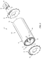
Fig. 3 is an exploded view of the wave rotor assembly showing that the wave rotor assembly includes the wave rotor combustor arranged to receive, combust, and exhaust the fuel-air mixture as part of a combustion process, the exit duct arranged to direct the gasses of the combustion process out of the rotor passages into the turbine, and the exhaust mixer located in a duct passage formed by the exit duct; -
Fig. 4 is a sectional view of the wave rotor assembly ofFig. 2 taken at line 4-4 showing that, as the wave rotor combustor rotates about the central axis, a number of rotor passages align with and open into the exit duct and that the exhaust mixer extends into the duct passage to redirect a portion of the gasses received by the exit duct; -
Fig. 5 is a sectional view of the exhaust mixer ofFig. 4 taken at line 5-5 showing that the exhaust mixer extends circumferentially and axially into the duct passage and that an inlet of the exhaust mixer is larger than an outlet of the exhaust mixer; -
Fig. 6 is a sectional view similar toFig. 4 showing that the exhaust mixer is positioned in the duct passage to redirect relatively-high velocity exhaust gasses received by the exit duct toward relatively-low velocity exhaust gasses received by the exit duct so that the relatively-high velocity exhaust gasses are mixed with the relatively-low velocity exhaust gasses in the duct passage; -
Fig. 7 is a sectional view of another embodiment of an exhaust mixer for use in the wave rotor assembly ofFig. 1 showing that, as the wave rotor combustor rotates about the central axis, a number of rotor passages align with and open into the exit duct and that the exhaust mixer extends into the duct passage to redirect a portion of the exhaust gasses received by the exit duct; -
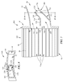
Fig. 8 is a sectional view of the exhaust mixer ofFig. 7 taken at line 8-8 showing that the exhaust mixer extends circumferentially and axially into the duct passage and that an outlet end of the exhaust mixer has a convoluted shape; -
Fig. 9 is a diagrammatic view of a cycle of the combustion process that occurs within each rotor passage of the wave rotor combustor and depicts the cycle of a single rotor passage at discrete circumferential positions as it completes a revolution about the central axis; and -
Fig. 10 is another diagrammatic view of a cycle of the combustion process that occurs within each rotor passage of the wave rotor combustor and depicts the cycle of a single rotor passage at continuous circumferential positions as it completes a revolution about the central axis. - For the purposes of promoting an understanding of the principles of the disclosure, reference will now be made to a number of illustrative embodiments illustrated in the drawings and specific language will be used to describe the same.
- An illustrative aerospace
gas turbine engine 100 includes awave rotor assembly 124 as part of anengine core 120 that powers afan assembly 130 as shown inFig. 1 . Thewave rotor assembly 124 combusts afueled air 354 as part of acombustion process 300 to power theengine 100. Anillustrative exhaust mixer 10 is included in thewave rotor assembly 124 to mix exhaust gasses produced during thecombustion process 300 as shown inFig. 2 . The mixed exhaust gasses have relatively more uniform temperature, velocity, and pressure than non-mixed exhaust gasses. Thewave rotor assembly 124 is an illustrative use of a wave rotor. In other embodiments, the disclosed features may be included in wave rotors used as pressure exchangers, flow dividers, flow combiners, etc. - The
wave rotor assembly 124 illustratively includes awave rotor combustor 125, anexit duct 50, and theexhaust mixer 10 as shown inFig. 2 . Thewave rotor combustor 125 receives the flow of fueledair 354 and ignites the fueledair 354 to power theengine core 120. Theexit duct 50 directs the combusted gasses from thewave rotor combustor 125 into aturbine 126 included in theengine core 120. Theexhaust mixer 10 mixes the gasses before the gasses enter theturbine 126 as suggested inFig. 6 . - In the illustrative embodiment, the
exhaust mixer 10 includes anexhaust passage 28, aninlet aperture 30 opening into theexhaust passage 28, and anoutlet aperture 32 opening into theexhaust passage 28. The relatively-high velocity exhaust gasses expelled from thewave rotor combustor 125 enter theexhaust passage 28 through theinlet aperture 30 as shown inFig. 6 . The relatively-low velocity exhaust gasses expelled from thewave rotor combustor 125 enter aduct passage 52 formed in theexit duct 50 and flow around theexhaust mixer 10. The relatively-high velocity exhaust gasses exit theexhaust passage 28 through theoutlet aperture 32 and, as such, are redirected toward the relatively-low velocity exhaust gasses received by theexit duct 50. As a result, the relatively-high velocity exhaust gasses are mixed with the relatively-low velocity exhaust gasses in theduct passage 52. In some embodiments, the exhaust gasses comprise relatively-high pressures and relatively-low pressures instead of or in addition to relatively-high velocities and relatively-low velocities respectively. - The
inlet aperture 30 includes an inlet area as shown inFigs. 4 and 5 . Theoutlet aperture 32 includes an outlet area. In the illustrative embodiment, the inlet area is greater than the outlet area. As such, theexhaust passage 28 is convergent and forms a nozzle. In the illustrative embodiment, theinlet aperture 30 and theoutlet aperture 32 are sized to cause gasses in theexhaust passage 28 to have a local sonic or supersonic velocity. - In the illustrative embodiment, the
exhaust mixer 10 includes afirst sidewall 12, asecond sidewall 14, a radialouter wall 16, and a radial inner wall 18 as shown inFig. 5 . The first andsecond sidewalls duct passage 52 relative to acentral axis 20 of theengine 100 to redirect the relatively-high velocity exhaust gasses toward the relatively-low velocity exhaust gasses. The radialouter wall 16 and the radial inner wall 18 extend between and inter connect the first andsecond sidewalls exhaust passage 28. - The
wave rotor combustor 125 is included in thewave rotor assembly 124 to receive and combust the fueledair 354 in thecombustion process 300 as shown inFigs. 2 ,9 , and10 . Thewave rotor combustor 125 is configured to use transient internal fluid flow to compress fuel and air prior to combustion to improve the efficiency of combustion within thewave rotor combustor 125. Thewave rotor combustor 125 is arranged to receive and combust the fueledair 354, which produces the exhaust gasses, as part of thecombustion process 300. - The
wave rotor combustor 125 includes aninlet assembly 78, arotor drum 70, and anoutlet assembly 82 as shown inFigs. 2 and3 . Theinlet assembly 78 is formed to include aninlet port 80 that extends circumferentially along an arc about thecentral axis 20 of thewave rotor assembly 124. Theoutlet assembly 82 is formed to include anoutlet port 84 that extends circumferentially along an arc about thecentral axis 20 of thewave rotor assembly 124. Therotor drum 70 is mounted for rotation relative to theinlet assembly 78 and theoutlet assembly 82 about thecentral axis 20. - The
rotor drum 70 is formed to include the plurality ofrotor passages 72 that extend along thecentral axis 20 as shown inFig. 2 . In the illustrative embodiment, therotor passages 72 rotate about thecentral axis 20 in a counter-clockwise direction as indicated byarrow 92. Therotor passages 72 are arranged so that therotor passages 72 align with theinlet port 80 at predetermined intervals when therotor drum 70 rotates about thecentral axis 20 to allow the fueledair 354 to flow through theinlet port 80 into therotor passages 72. Therotor passages 72 align with theoutlet port 84 at predetermined intervals when therotor drum 70 rotates about thecentral axis 20 to allow the gasses in therotor passages 72 to flow through theoutlet port 84 into theexit duct 50. - The
exit duct 50 directs the exhaust gasses out of thewave rotor combustor 125 into theturbine 126 included in theengine 100 as shown inFig. 1 . Theexit duct 50 is coupled to theoutlet assembly 82 and extends axially away from thewave rotor combustor 125 toward theturbine 126. - The
exit duct 50 defines an axially extendingduct passage 52, aduct inlet 54 opening into theduct passage 52, and aduct outlet 56 opening into theduct passage 52. The exhaust gasses flowing through theoutlet port 84 flow through theduct inlet 54 into theduct passage 52 and exit through theduct outlet 56. - As each
rotor passage 72 opens into theoutlet port 84, the exhaust gasses expand and exit therotor passage 72 through the relatively low-pressure outlet port 84. A first portion of exhaust gasses exiting theoutlet port 84 and received in theduct passage 52 are relatively hot and have a relatively high-velocity. As therotor passage 72 continues to rotate, the gasses within therotor passage 72 continue to expand and exit through theoutlet port 84. A second portion of exhaust gasses exiting through theoutlet port 84 and received in theduct passage 52 are relatively cooler and have a relatively-low velocity due to the expansion of the exhaust gasses. - The
exhaust mixer 10 is arranged to redirect the relatively-high velocity exhaust gasses received by theexit duct 50 toward the relatively-low velocity exhaust gasses received by theexit duct 50 so that the relatively-high velocity exhaust gasses are mixed with the relatively-low velocity exhaust gasses in theduct passage 52 as suggested inFig. 6 . In the illustrative embodiment, theexhaust mixer 10 is positioned in theduct passage 52 to receive the relatively-high velocity exhaust gasses as shown inFigs. 4-6 . The relatively-low velocity exhaust gasses are received in theduct passage 52 and flow around theexhaust mixer 10. Theexhaust mixer 10 extends axially and circumferentially into theduct passage 52 to redirect the relatively-high velocity exhaust gasses toward the relatively-low velocity exhaust gasses. - The
exhaust mixer 10 includes afront end 24 and aback end 26 axially spaced part from thefront end 24 as shown inFig. 4 . Theexhaust mixer 10 extends axially between the front and back ends 24, 26. Theexhaust mixer 10 is formed to include theexhaust passage 28, theinlet aperture 30, and theoutlet aperture 32 as shown inFig. 4 . Theexhaust passage 28 extends through theexhaust mixer 10 between the front and back ends 24, 26 to provide a flow path for the relatively-high velocity exhaust gasses. - The
inlet aperture 30 opens into theexhaust passage 28 at thefront end 24 of theexhaust mixer 10. Theinlet aperture 30 is positioned at a front of theduct passage 52 to receive the relatively-high velocity exhaust gasses that exit therotor passages 72 through theoutlet port 84. The relatively-high velocity exhaust gasses flow throughinlet aperture 30 into theexhaust passage 28. - The
outlet aperture 32 opens into theexhaust passage 28 at theback end 26 of theexhaust mixer 10. The relatively-high velocity exhaust gasses exit theexhaust passage 28 through theoutlet aperture 32 toward the relatively-low velocity exhaust gasses in theduct passage 52. - The mixing of the relatively-high velocity exhaust gasses and the relatively-low velocity gasses may cause the velocity of the high-velocity exhaust gasses to decrease while increasing the average velocity of the exhaust gasses. The mixing may cause the temperature of the relatively-high velocity exhaust gasses to decrease and the temperature of the relatively-low velocity exhaust gasses to increase. As such, the temperature of the exhaust gasses may be more uniform. Additionally, the amount of noise produced by the
wave rotor assembly 124 may be reduced. - The
inlet aperture 30 includes the inlet area. Theoutlet aperture 32 includes the outlet area. In the illustrative embodiment, the inlet area is greater than the outlet area. As such, theexhaust passage 28 is convergent and forms a nozzle. In the illustrative embodiment, theinlet aperture 30 and theoutlet aperture 32 are sized to cause the gasses in theexhaust passage 28 to have a local sonic or supersonic velocity. In other embodiments, theback end 26 of theexhaust mixer 10 has a convoluted shape as shown inFigs. 7 and 8 . - In the illustrative embodiment, the
exhaust mixer 10 includes thefirst sidewall 12, thesecond sidewall 14, the radialouter wall 16, and the radial inner wall 18 as shown inFigs. 3-6 . Thefirst sidewall 12, thesecond sidewall 14, the radialouter wall 16, and the radial inner wall 18 cooperate to define theexhaust passage 28, theinlet aperture 30, and theoutlet aperture 32 as shown inFigs. 4 and 5 . - The
first sidewall 12 extends axially and circumferentially into theduct passage 52 relative to thecentral axis 20 to redirect the relatively-high velocity exhaust gasses toward the relatively-low velocity exhaust gasses. Thefirst sidewall 12 is coupled to and extends from theexit duct 50 at thefront end 24 of theexhaust mixer 10. In the illustrative embodiment, thefirst sidewall 12 extends between and interconnects outer and inner radial walls of theexit duct 50 at the front end of theexhaust mixer 10. A height of thefirst sidewall 12 decreases from thefront end 24 to theback end 26 of theexhaust mixer 10 as shown inFig. 5 . - The
second sidewall 14 is spaced apart circumferentially from thefirst sidewall 12 as shown inFigs. 4 and 5 . Thesecond sidewall 14 is coupled to and extends from theexit duct 50 at thefront end 24 of theexhaust mixer 10. Thesecond sidewall 14 extends axially and circumferentially into theduct passage 52 to redirect the relatively-high velocity exhaust gasses toward the relatively-low velocity exhaust gasses. In the illustrative embodiment, thesecond sidewall 14 extends between and interconnects the outer and inner radial walls of theexit duct 50 at the front end of theexhaust mixer 10. A height of thesecond sidewall 14 decreases from thefront end 24 to theback end 26 of theexhaust mixer 10 as shown inFig. 5 . - Illustratively, the
second sidewall 14 includes afore leg 34 and anaft leg 36 as shown inFig. 4 . Thefore leg 34 extends axially into theduct passage 52. Theaft leg 36 extends from thefore leg 34 axially and circumferentially into theduct passage 52. - The radial
outer wall 16 is spaced apart radially from thecentral axis 20 as shown inFig. 5 . The radialouter wall 16 extends circumferentially between and interconnects the first andsecond sidewalls exhaust passage 28 extending through theexhaust mixer 10. - The radial inner wall 18 is spaced apart radially from the
central axis 20 as shown inFig. 5 . The radial inner wall 18 is located radially between the radialouter wall 16 and thecentral axis 20. The radial inner wall 18 extends circumferentially between and interconnects the first andsecond sidewalls exhaust passage 28 extending through theexhaust mixer 10. - Another
illustrative exhaust mixer 210 for use in thewave rotor assembly 124 is shown inFigs. 7 and 8 . Theexhaust mixer 210 is substantially similar to theexhaust mixer 10 shown inFigs. 1-6 and described herein. Accordingly, similar reference numbers in the 200 series indicate features that are common between theexhaust mixer 10 and theexhaust mixer 210. The description of theexhaust mixer 10 is hereby incorporated by reference to apply to theexhaust mixer 210, except in instances when it conflicts with the specific description and drawings of theexhaust mixer 210. - The
back end 226 of theexhaust mixer 210 is formed to have a plurality oflobes 238 to form a convoluted shape as shown inFigs. 7 and 8 . The convoluted shape may increase the mixing of the relatively-high velocity exhaust gasses and the relatively-low velocity exhaust gasses. Thefirst sidewall 12, thesecond sidewall 14, the radialouter wall 16, and the radial inner wall 18 are deformed at theback end 226 of theexhaust mixer 210 to form the convoluted shape. - The
wave rotor assembly 124 is included in the gasturbine engine core 120 to power theturbine 126 as shown, for example, inFig. 1 . Theengine core 120 includes thecompressor 122, thewave rotor assembly 124, and theturbine 126. Thecompressor 122 is configured to compress and deliver air to thewave rotor assembly 124. Theturbine 126 extracts work from the combusted gasses (sometimes called hot high-pressure products or exhaust gasses) to drive thecompressor 122 and thefan assembly 130. Thefan assembly 130 pushes air through and around theengine 100 to provide thrust for an aircraft. - During operation of the
wave rotor assembly 124, fuel and compressed air, produced by thecompressor 122, is drawn axially into eachrotor passage 72 through theinlet port 80 formed in theinlet assembly 78 as shown inFigs. 2 and3 . As eachrotor passage 72 rotates about thecentral axis 20, the compressed air and fuel are mixed together and are then ignited to produce the hot high-pressure products. The hot high-pressure products are blocked from escaping therotor passage 72 by theinlet assembly 78 and anoutlet assembly 82 until therotor passage 72 aligns with anoutlet port 84 formed in theoutlet assembly 82. The hot high-pressure products exit therotor passage 72 through theoutlet port 84 into theturbine 126. - In the illustrative embodiment, the
wave rotor combustor 125 includes theinlet assembly 78, theoutlet assembly 82 spaced apart from theinlet assembly 78 along thecentral axis 20 of theengine 100, and therotor drum 70 positioned therebetween as shown inFigs. 2 and3 . The inlet andoutlet assemblies rotor drum 70 to form a gap between therotor drum 70 and eachassembly rotor passages 72. In some embodiments, theassemblies rotor drum 70 to minimize leakage of flow out of therotor passage 72. - In the illustrative embodiment, the
inlet assembly 78 includes asingle inlet port 80 and theoutlet assembly 82 includes asingle outlet port 84. In other embodiments, theinlet assembly 78 is formed to include a plurality ofinlet ports 80 and theoutlet assembly 82 is formed to include a plurality ofoutlet ports 84. - The
rotor drum 70 is mounted for rotation about thecentral axis 20 relative to theinlet assembly 78 andoutlet assembly 82 as suggested byarrow 92 inFig. 2 . In other embodiments, therotor drum 70 rotates in an opposite direction. Therotor drum 70 includes aninlet end 74 and anoutlet end 76. Therotor drum 70 extends axially along thecentral axis 20 between the inlet and outlet ends 74, 76. - The
rotor drum 70 includes anouter tube 86, aninner tube 88, and a plurality ofwebs 90 as shown inFig. 2 . Theouter tube 86, theinner tube 88, and the plurality ofwebs 90 cooperate to form the plurality of axially extendingrotor passages 72. In the illustrative embodiment, therotor passages 72 extend axially and generally parallel with thecentral axis 20. In other embodiments, therotor passages 72 extend axially along and circumferentially about thecentral axis 20. - The
outer tube 86 extends around thecentral axis 20 to form a radially outer portion of therotor passages 72. Theinner tube 88 extends around thecentral axis 20 and is positioned radially between thecentral axis 20 and theouter tube 86 to form a radially inner portion of therotor passages 72. The plurality ofwebs 90 are spaced apart circumferentially and extend between and interconnect theouter tube 86 and theinner tube 88 to separate the plurality ofrotor passages 72. - In the illustrative embodiment, the
rotor passages 72 are generally parallel with thecentral axis 20 and therotor drum 70 is rotated by adrive shaft 62. In other embodiments, therotor passages 72 extend axially along and circumferentially around thecentral axis 20. In some embodiments, therotor passages 72 are arranged to cause therotor drum 70 to rotate as a result of the shape of therotor passages 72 and the combustion process that occurs within therotor passages 72. - An
illustrative combustion process 300 occurs within therotor passages 72 as therotor passages 72 rotate about thecentral axis 20 as suggested inFigs. 9 and10 . Thecombustion process 300 is substantially a constant volume combustion process. - The
combustion process 300 occurs in eachrotor passage 72 of thewave rotor combustor 125 as depicted in a space-time wave diagram shown inFigs. 9 and10 . The wave diagram shown inFig. 9 depicts the sequence of events occurring during one cycle within arotor passage 72 at discrete circumferential positions. Thearrow 92 indicates the direction of rotation of therotor passage 72. Upon the rotation of therotor drum 70, each of therotor passages 72 are sequentially brought into alignment with theinlet port 80 and theoutlet port 84. - The
combustion process 300 is depicted in another space-time wave diagram shown inFig. 10 . The wave diagram shown inFig. 10 depicts the sequence of events occurring during one cycle within arotor passage 72 in continuous circumferential positions. Thearrow 92 indicates the direction of rotation of therotor passage 72. - The
combustion process 300 is periodic such that the top of each wave diagram loops around and join with itself at the bottom of the diagram. The wave diagrams, for the purpose of description, may be started at any point. However, for convenience, the description is started atstep 302 corresponding to the bottom of the wave diagrams shown inFigs. 9 and10 . - In
step 302, theinlet end 74 of therotor passage 72 is blocked by theinlet assembly 78. Theoutlet end 76 of therotor passage 72 is aligned with and opens into theoutlet port 84 formed in theoutlet assembly 82. Therotor passage 72 containsunfueled air 356 and combustedgas products 352. The combustedgas products 352 are hot high-pressure products resulting from the combustion of the fueledair 354. - As the
rotor passage 72 opens into theoutlet port 84, the combustedgas products 352 expand and exit therotor passage 72 through the relatively low-pressure outlet port 84. Afirst expansion wave 360 originates from the outlet end 76 of therotor passage 72 and propagates toward theinlet end 74 expelling the combustedgas products 352 through theoutlet port 84. The combustedgas products 352 exiting theoutlet port 84 are relatively hot and relatively-high velocity exhaust gasses. The relatively-high velocity exhaust gasses flow through theexhaust passage 28 of theexhaust mixer 10 as shown inFigs. 9 and10 . Thefirst expansion wave 360 may reflect at theinlet end 74 and may be redirected toward theoutlet end 76. - Illustratively, the
exhaust mixer 10 alters thecombustion process 300 as compared to a wave rotor without anexhaust mixer 10. Theexhaust mixer 10 alters the internalwave rotor cycle 300 such that two sets of expansions occur within the rotor passages which may more efficiently expand the gasses to arrive at a greater total pressure rise for the combustor as well as a more uniform set of exhaust properties. Thewav rotor assembly 124 has at least two stages of expansion which are used to more adequately capture the pressure gain potential. - As the
rotor passage 72 continues to rotate, asecond expansion wave 362 originates from the outlet end 76 of therotor passage 72 at thefore leg 34 and propagates toward theinlet end 74 expelling the combustedgas products 352 through theoutlet port 84 as shown inFig. 10 . As such, the combustedgas products 352 continue to expand and exit through theoutlet port 84 and theunfueled air 356 expands toward theoutlet port 84. The combustedgas products 352 exiting through theoutlet port 84 after thesecond expansion wave 362 are relatively cooler and relatively-low velocity exhaust gasses due to the expansion of the combustedgas products 352. The relatively-low velocity gasses flow through theduct passage 52 of theexit duct 50 around theexhaust mixer 10 as shown inFigs. 9 and10 . The relatively-high velocity gasses exit theexhaust mixer 10 at theback 26 of theexhaust mixer 10 and are directed toward the relatively-low velocity gasses to mix the exhaust gasses. - In a
step 304, therotor passage 72 aligns with and opens into theinlet port 80. The fueledair 354 is directed through theinlet port 80 into therotor passage 72. The fueledair 354 has relatively greater pressure than the remainingunfueled air 356 and combustedgas products 352. As such, the fueledair 354 is drawn into therotor passage 72 and theunfueled air 356 and combustedgas products 352 flow axially through theoutlet port 84. - In the illustrative embodiment, the
compressor 122 provides a flow ofunfueled air 356 upstream of theinlet port 80. Illustratively, fuel nozzles continuously spray fuel into a portion of the flow ofunfueled air 356 upstream of theinlet port 80. The fuel and air mix before entering therotor passage 72 to form the fueledair 354. The fueledair 354 is separated from the combustedgas products 352 in therotor passage 72 by theunfueled air 356. As such, the fueledair 354 is blocked from unintentional ignition. - In a
step 306, the fueledair 354 continues to be directed into therotor passage 72 until theunfueled air 356 has been significantly expelled out of therotor passage 72. Theunfueled air 356 is relatively cooler than the combustedgas products 352. The relatively-high velocity exhaust gasses exiting theexhaust mixer 10 are mixed with theunfueled air 356. - The
wave rotor combustor 125 is arranged such that, as theunfueled air 356 is significantly expelled out of therotor passage 72, therotor passage 72 rotates beyond theoutlet port 84. As a result, theoutlet assembly 82 blocks the fueledair 354 from escaping through the outlet end 76 of therotor passage 72. When the outlet end 76 of therotor passage 72 is closed by theoutlet assembly 82, ashock wave 394 begins at the outlet end 76 of therotor passage 72 and propagates toward theinlet end 74. Theshock wave 394 causes the fueledair 354 to compress. - In a
step 308, the flow of fueledair 354 ends and the flow ofunfueled air 356 continues to enter therotor passage 72 due to the pressure in therotor passage 72 being lower than the pressure at theinlet 80. The compressingshock 394 compresses the fueledair 354 and theunfueled air 356. - In a
step 310, therotor passage 72 rotates beyond theinlet port 80 to block the flow ofunfueled air 356 from entering therotor passage 72. The fluid within therotor passage 72 is blocked from escaping therotor passage 72 by theinlet assembly 78 at theinlet end 74 and by theoutlet assembly 82 at theoutlet end 76. Anignition source 396 ignites the compressed fueledair 354 at the outlet end 76 of therotor passage 72. In other embodiments, the compressed fueledair 354 ignites as a result of auto-ignition. - As the fueled
air 354 combusts, the fueledair 354 expands to form the combustedgas products 352. The portion of theunfueled air 356 that did not receive fuel added by the fuel nozzle, having entered duringstep 308, experiences no combustion and is compressed byshock wave 394. The combustedgas products 352 expand and further compress theunfueled air 356. Therotor passage 72 continues to rotate about thecentral axis 20 and returns to step 302 at the bottom of the wave diagram shown inFigs. 9 and10 . - Some wave rotor pressure gain combustors use one discharge port for exhaust gasses. A wave rotor with on board combustion may have exhaust flow having a large variation in both temperature and stagnation pressure, in particular, in the circumferential direction. Some simple on-board combustion wave rotor cycles have high variation in exhaust gas properties within the single exhaust port. The temperatures may range from near peak combustion temperature to that of the inlet air temperature. The stagnation pressure may have with the exit velocity which may range from supersonic to subsonic in nature. Some wave rotors involve turbomachinery downstream of the exit of the wave rotor. As such, wave rotors with compatible components are desired.
- According to an aspect of the present disclosure, a method by which, external to the
wave rotor passage 72, exhaust gasses are mixed to provide a uniform exit velocity pattern. The mixing of the gasses and causes the temperature and pressure pattern into downstream turbine components to be similar to those experienced in other gas turbines. Theexhaust mixer 10 alters the internal wave rotor cycle such that two sets of expansions occur within the rotor passages which may more efficiently expand the gasses to arrive at a greater total pressure rise for the combustor as well as a more uniform set of exhaust properties. As such, a portion of the high temperature, high velocity gasses may not need to be bypassed into a high pressure turbine before mixing with the low energy gasses. - The
wave rotor assembly 124 includes a first port to deliver an expansion of hot combustion gasses in therotor passages 72 to a first static pressure Ps1. As therotor passage 72 moves out of the first port, it encounters a second exit port at a lower static pressure PsA and the gasses exiting therotor passage 72 undergo a second expansion. Flow within the portion of theexhaust mixer 10, connected to the first port, experiences a turn and an area reduction resulting in a flow at a local sonic or supersonic velocity at the exit of theexhaust mixer 10 as shown inFig. 4 . The static pressure at the exit of theexhaust mixer 10 is about PsA. - With the resulting stagnation pressure of the flow exiting the
exhaust mixer 10 being high relative to that induct passage 52, an ejector mixing process is accomplished within the portion of the passage downstream of theduct passage 52 and a portion of the total energy both thermal and kinetic is transferred to the exhaust flow of theduct passage 52. The ejector action may cause the static pressure within theduct passage 52 to be reduced compared to that were such ejector action is not present. This may cause a more rapid discharge of the flow in theduct passage 52 which may add to its stagnation pressure and cause the discharge of the gasses to be accomplished in a more rapid manner. - According to another aspect of the present disclosure, the
wave rotor assembly 124 may use the observation that hot, high velocity gas occurs at the extreme inlet edge of theoutlet port 84. The remainder of theoutlet port 84 is filled with lower temperature and lower velocity gasses. Thewave rotor assembly 124 divides theoutlet port 84 into at least two portions choosing the dividing point to capture the different energy level gasses. Theexhaust mixer 10 is formed in theexit duct 50 shaping the duct to locate the higher temperature, higher velocity flow near the center of theduct passage 52 and providing annular space around theexhaust mixer 10 so that the lower velocity, higher static pressure portion of the flow can flow around it. The two flows are released and allowed to mix as they flow toward the downstream components. - The hot, high velocity gasses act as an ejector which drags the low energy, but high static pressure gasses along causing turbulent mixing along the
duct passage 52 to the downstream turbine. In some embodiments, theexhaust mixer 10 uses the concept of convolutions in the exit lip of theexhaust mixer 10 so that the hot, high velocity gasses are brought into intimate contact with the cool, low velocity gas over an increased perimeter. - While the disclosure has been illustrated and described in detail in the foregoing drawings and description, the same is to be considered as exemplary and not restrictive in character, it being understood that only illustrative embodiments thereof have been shown and described and that all changes and modifications that come within the spirit of the disclosure are desired to be protected.
Claims (15)
- A wave rotor assembly comprising
a wave rotor combustor including an aft plate formed to include an exit port that extends circumferentially along an arc about a central axis of the combustor assembly and a rotor drum mounted for rotation relative to the aft plate about the central axis, the rotor drum formed to include a plurality of rotor passages that extend along the central axis and are arranged so that the rotor passages align with the exit port at predetermined intervals when the rotor drum rotates about the central axis to allow exhaust gasses in the rotor passages to flow through the exit port,
an exit duct coupled to the aft plate that defines a duct passage arranged to receive the exhaust gasses flowing through the exit port, and
an exhaust mixer located in the duct passage and arranged to circumferentially redirect relatively-high velocity exhaust gasses received by the exit duct toward relatively-low velocity exhaust gasses received by the exit duct so that the relatively-high velocity exhaust gasses are mixed with the relatively-low velocity exhaust gasses in the duct passage. - The wave rotor assembly of claim 1, wherein the exhaust mixer includes a first sidewall that extends axially and circumferentially into the duct passage relative to the central axis to redirect the relatively-high velocity exhaust gasses toward the relatively-low velocity exhaust gasses.
- The wave rotor assembly of claim 2, wherein the exhaust mixer further includes a second sidewall spaced apart circumferentially from the first sidewall and the second sidewall extends axially and circumferentially into the duct passage to redirect the relatively-high velocity exhaust gasses toward the relatively-low velocity exhaust gasses.
- The wave rotor assembly of claim 3, wherein the second sidewall includes a forward leg that extends axially into the duct passage and an aft leg that extends from the forward leg axially and circumferentially into the duct passage.
- The wave rotor assembly of claim 3, wherein the exhaust mixer further includes a radial outer wall and a radial inner wall spaced apart radially from the radial outer wall relative to the central axis and the radial outer wall and the radial inner wall extend between and interconnect the first and second sidewalls to form a mixer passage extending through the exhaust mixer; optionally
wherein the exhaust mixer includes a front end and a back end axially spaced apart from the front end relative to the central axis, a height of the first sidewall decreases from the front end to the back end, and a height of the second sidewall decreases from the front end to the back end. - The wave rotor assembly of claim 1, wherein the exhaust mixer forms a mixer passage extending through the exhaust mixer, an inlet aperture opening into the mixer passage, and an outlet aperture opening into the mixer passage.
- The wave rotor assembly of claim 6, wherein the inlet aperture has an inlet area, the outlet aperture has an outlet area, and the inlet area is greater than the outlet area; optionally wherein the relatively-high velocity exhaust gasses exit the exhaust mixer through the outlet aperture at a supersonic velocity.
- The wave rotor assembly of claim 6, wherein the exhaust mixer has a front end adjacent to the inlet aperture and a back end axially spaced apart from the front end and the back end has a convoluted shape.
- A wave rotor assembly comprising
a wave rotor combustor including an aft plate formed to include an exit port and a rotor drum mounted for rotation relative to the aft plate, the rotor drum formed to include a plurality of rotor passages arranged to align with the exit port during rotation of the rotor drum,
an exit duct coupled to the aft plate that defines a duct passage arranged to receive exhaust gasses flowing through the exit port, and
an exhaust mixer located in the duct passage and arranged to redirect the exhaust gasses received by the exit duct. - The wave rotor assembly of claim 9, wherein the exhaust mixer:(i) is arranged to redirect relatively-high velocity exhaust gasses received by the exit duct in a circumferential direction toward relatively-low velocity exhaust gasses received by the exit duct so that the relatively-high velocity exhaust gasses are mixed with the relatively-low velocity exhaust gasses in the duct passage; or(ii) includes a first sidewall that extends axially and circumferentially into the duct passage to redirect the relatively-high velocity exhaust gasses toward the relatively-low velocity exhaust gasses, optionally
wherein the exhaust mixer includes a second sidewall that is circumferentially spaced apart from the first sidewall and extends axially and circumferentially into the duct passage to redirect the relatively-high velocity exhaust gasses toward the relatively-low velocity exhaust gasses; or(iii) is formed to include a mixer passage extending through the exhaust mixer, an inlet aperture opening into the mixer passage, and an outlet aperture opening into the mixer passage, the inlet aperture has an inlet area, the outlet aperture has an outlet area, and the inlet area is greater than the outlet area. - The wave rotor assembly of claim 10 (iii), wherein the exhaust mixer includes a first sidewall, a second sidewall circumferentially spaced apart from the first sidewall, a radial outer wall, and a radial inner wall spaced apart radially from the radial outer wall relative to the central axis and the radial outer wall and the radial inner wall extend between and interconnect the first and second sidewalls between the front and back ends to define the mixer passage; optionally
wherein the exhaust mixer includes a front end and a back end axially spaced apart from the front end relative to a central axis of the combustor assembly, a height of the first sidewall decreases from the front end to the back end, and a height of the second sidewall decreases from the front end to the back end. - The wave rotor assembly of claim 10 (iii), wherein the relatively-high velocity exhaust gasses exit the exhaust mixer through the outlet aperture at a local sonic velocity.
- A method of making a wave rotor assembly, the method comprising
providing a wave rotor, an exit duct, and an exhaust mixer, the wave rotor including an aft plate formed to include an exit port and a rotor drum mounted for rotation relative to the aft plate, the rotor drum formed to include a plurality of rotor passages arranged to align with the exit port at predetermined intervals during rotation of the rotor drum, and the exit duct defines a duct passage,
coupling the exit duct to the aft plate to cause the duct passage to be arranged to receive exhaust gasses flowing through the exit port, and
locating the exhaust mixer in the duct passage to redirect exhaust gasses received by the exit duct. - The method of claim 13, wherein the exit duct is arranged to receive relatively-low velocity exhaust gasses and relatively-high velocity exhaust gasses and the exhaust mixer is arranged to redirect the relatively-high velocity exhaust gasses received by the exit duct toward the relatively-low velocity exhaust gasses received by the exit duct so that the relatively-high velocity exhaust gasses are mixed with the relatively-low velocity exhaust gasses in the duct passage.
- The method of claim 14, wherein the exhaust mixer is arranged to cause relatively-high pressure exhaust gasses located in the rotor passages aligned circumferentially with the exhaust mixer to undergo a first expansion; optionally
wherein the exit duct is arranged to cause relatively-low velocity exhaust gasses located in the rotor passages aligned circumferentially with the exit duct to undergo a second expansion.
Applications Claiming Priority (1)
| Application Number | Priority Date | Filing Date | Title |
|---|---|---|---|
| US201562114919P | 2015-02-11 | 2015-02-11 |
Publications (2)
| Publication Number | Publication Date |
|---|---|
| EP3056713A1 true EP3056713A1 (en) | 2016-08-17 |
| EP3056713B1 EP3056713B1 (en) | 2017-10-25 |
Family
ID=55300367
Family Applications (1)
| Application Number | Title | Priority Date | Filing Date |
|---|---|---|---|
| EP16153420.1A Not-in-force EP3056713B1 (en) | 2015-02-11 | 2016-01-29 | Exhaust mixer for wave rotor assembly |
Country Status (2)
| Country | Link |
|---|---|
| US (1) | US10443493B2 (en) |
| EP (1) | EP3056713B1 (en) |
Families Citing this family (5)
| Publication number | Priority date | Publication date | Assignee | Title |
|---|---|---|---|---|
| US9926891B2 (en) * | 2015-11-18 | 2018-03-27 | General Electric Company | System and method of exhaust gas recirculation |
| US12398670B2 (en) * | 2019-02-20 | 2025-08-26 | Green Engine, Llc | Rotating internal combustion engine |
| CN112627905B (en) * | 2020-12-18 | 2022-05-03 | 常州工学院 | Internal combustion wave rotor exhaust mixing device based on blade diversion pressure relief |
| CN115822987B (en) * | 2022-12-19 | 2026-03-06 | 北京航空航天大学宁波创新研究院 | A supercritical carbon dioxide compressor |
| US12582733B2 (en) | 2023-03-12 | 2026-03-24 | Tru-D Smartuvc, Llc | Parallel heating system and method for amalgam lamps |
Citations (4)
| Publication number | Priority date | Publication date | Assignee | Title |
|---|---|---|---|---|
| EP0503277A1 (en) * | 1991-03-12 | 1992-09-16 | Asea Brown Boveri Ag | Gasturbine plant |
| EP1710417A2 (en) * | 2005-03-24 | 2006-10-11 | United Technologies Corporation | Pulse combustion device |
| US20070157625A1 (en) * | 2002-07-03 | 2007-07-12 | Snyder Philip H | Constant volume combustor |
| CN103133138A (en) * | 2013-01-18 | 2013-06-05 | 南京航空航天大学 | Internal combustion wave rotor based on non-constant combustion and with pressurization function and working method thereof |
Family Cites Families (11)
| Publication number | Priority date | Publication date | Assignee | Title |
|---|---|---|---|---|
| US2904242A (en) * | 1956-06-28 | 1959-09-15 | Ronald D Pearson | Pressure exchangers |
| US3417564A (en) * | 1967-04-19 | 1968-12-24 | John G. Call | Jet engine with relatively rotatable combustion means, intake manifold and exhaust manifold |
| US6460342B1 (en) * | 1999-04-26 | 2002-10-08 | Advanced Research & Technology Institute | Wave rotor detonation engine |
| US6449939B1 (en) | 2000-05-26 | 2002-09-17 | Rolls-Royce Corporation | Pulsed detonation engine wave rotor |
| US6526936B2 (en) | 2000-07-06 | 2003-03-04 | Advanced Research And Technology Institute | Partitioned multi-channel combustor |
| US7137243B2 (en) | 2002-07-03 | 2006-11-21 | Rolls-Royce North American Technologies, Inc. | Constant volume combustor |
| US20060260291A1 (en) | 2005-05-20 | 2006-11-23 | General Electric Company | Pulse detonation assembly with cooling enhancements |
| US7526912B2 (en) | 2005-10-31 | 2009-05-05 | General Electric Company | Pulse detonation engines and components thereof |
| WO2008070210A2 (en) | 2006-06-15 | 2008-06-12 | Indiana University Research And Technology Corporation | Pilot fuel injection for a wave rotor engine |
| US20090102203A1 (en) | 2007-10-23 | 2009-04-23 | Lu Frank K | System and method for power production using a hybrid helical detonation device |
| US9021783B2 (en) * | 2012-10-12 | 2015-05-05 | United Technologies Corporation | Pulse detonation engine having a scroll ejector attenuator |
-
2016
- 2016-01-29 EP EP16153420.1A patent/EP3056713B1/en not_active Not-in-force
- 2016-02-11 US US15/041,191 patent/US10443493B2/en active Active
Patent Citations (4)
| Publication number | Priority date | Publication date | Assignee | Title |
|---|---|---|---|---|
| EP0503277A1 (en) * | 1991-03-12 | 1992-09-16 | Asea Brown Boveri Ag | Gasturbine plant |
| US20070157625A1 (en) * | 2002-07-03 | 2007-07-12 | Snyder Philip H | Constant volume combustor |
| EP1710417A2 (en) * | 2005-03-24 | 2006-10-11 | United Technologies Corporation | Pulse combustion device |
| CN103133138A (en) * | 2013-01-18 | 2013-06-05 | 南京航空航天大学 | Internal combustion wave rotor based on non-constant combustion and with pressurization function and working method thereof |
Also Published As
| Publication number | Publication date |
|---|---|
| EP3056713B1 (en) | 2017-10-25 |
| US10443493B2 (en) | 2019-10-15 |
| US20160230656A1 (en) | 2016-08-11 |
Similar Documents
| Publication | Publication Date | Title |
|---|---|---|
| CN109028146B (en) | Hybrid combustor assembly and method of operation | |
| CN109028151B (en) | Multi-chamber rotary detonation combustor | |
| CN109028142B (en) | Propulsion system and method of operating the same | |
| CN109028144B (en) | Integral vortex rotary detonation propulsion system | |
| US20180231256A1 (en) | Rotating Detonation Combustor | |
| US11149954B2 (en) | Multi-can annular rotating detonation combustor | |
| CA2452972C (en) | Methods and apparatus for generating gas turbine engine thrust | |
| US10443493B2 (en) | Exhaust mixer for wave rotor assembly | |
| CN113266850A (en) | Variable geometry rotary detonation combustor and method of operating same | |
| US20180355792A1 (en) | Annular throats rotating detonation combustor | |
| US12092336B2 (en) | Turbine engine assembly including a rotating detonation combustor | |
| US20180355795A1 (en) | Rotating detonation combustor with fluid diode structure | |
| US20190017437A1 (en) | Continuous detonation gas turbine engine | |
| US6868665B2 (en) | Methods and apparatus for operating gas turbine engines | |
| US7779866B2 (en) | Segmented trapped vortex cavity | |
| US20160102609A1 (en) | Pulse detonation combustor | |
| US20180179950A1 (en) | Turbine engine assembly including a rotating detonation combustor | |
| JP2014525557A (en) | Combustion chamber wall | |
| CN110529876A (en) | Rotating Detonation Combustion System | |
| US20190242582A1 (en) | Thermal Attenuation Structure For Detonation Combustion System | |
| US9021783B2 (en) | Pulse detonation engine having a scroll ejector attenuator | |
| US10393383B2 (en) | Variable port assemblies for wave rotors | |
| KR20220104493A (en) | Nozzle assembly, combustor and gas turbine comprising the same | |
| KR102720523B1 (en) | Jet nozzle, combustor and gas turbine including same | |
| US20160245526A1 (en) | Wave rotors with temperature control features |
Legal Events
| Date | Code | Title | Description |
|---|---|---|---|
| PUAI | Public reference made under article 153(3) epc to a published international application that has entered the european phase |
Free format text: ORIGINAL CODE: 0009012 |
|
| AK | Designated contracting states |
Kind code of ref document: A1 Designated state(s): AL AT BE BG CH CY CZ DE DK EE ES FI FR GB GR HR HU IE IS IT LI LT LU LV MC MK MT NL NO PL PT RO RS SE SI SK SM TR |
|
| AX | Request for extension of the european patent |
Extension state: BA ME |
|
| RIN1 | Information on inventor provided before grant (corrected) |
Inventor name: EMMERSON, CALVIN W. Inventor name: SNYDER, PHILIP H. |
|
| 17P | Request for examination filed |
Effective date: 20170209 |
|
| RBV | Designated contracting states (corrected) |
Designated state(s): AL AT BE BG CH CY CZ DE DK EE ES FI FR GB GR HR HU IE IS IT LI LT LU LV MC MK MT NL NO PL PT RO RS SE SI SK SM TR |
|
| GRAP | Despatch of communication of intention to grant a patent |
Free format text: ORIGINAL CODE: EPIDOSNIGR1 |
|
| RIC1 | Information provided on ipc code assigned before grant |
Ipc: F02C 3/16 20060101AFI20170331BHEP Ipc: F23R 3/56 20060101ALI20170331BHEP Ipc: F01D 9/02 20060101ALI20170331BHEP Ipc: F02C 5/04 20060101ALI20170331BHEP |
|
| INTG | Intention to grant announced |
Effective date: 20170420 |
|
| GRAS | Grant fee paid |
Free format text: ORIGINAL CODE: EPIDOSNIGR3 |
|
| GRAJ | Information related to disapproval of communication of intention to grant by the applicant or resumption of examination proceedings by the epo deleted |
Free format text: ORIGINAL CODE: EPIDOSDIGR1 |
|
| GRAL | Information related to payment of fee for publishing/printing deleted |
Free format text: ORIGINAL CODE: EPIDOSDIGR3 |
|
| GRAR | Information related to intention to grant a patent recorded |
Free format text: ORIGINAL CODE: EPIDOSNIGR71 |
|
| GRAA | (expected) grant |
Free format text: ORIGINAL CODE: 0009210 |
|
| INTC | Intention to grant announced (deleted) | ||
| AK | Designated contracting states |
Kind code of ref document: B1 Designated state(s): AL AT BE BG CH CY CZ DE DK EE ES FI FR GB GR HR HU IE IS IT LI LT LU LV MC MK MT NL NO PL PT RO RS SE SI SK SM TR |
|
| INTG | Intention to grant announced |
Effective date: 20170919 |
|
| REG | Reference to a national code |
Ref country code: GB Ref legal event code: FG4D |
|
| REG | Reference to a national code |
Ref country code: CH Ref legal event code: EP |
|
| REG | Reference to a national code |
Ref country code: AT Ref legal event code: REF Ref document number: 940184 Country of ref document: AT Kind code of ref document: T Effective date: 20171115 |
|
| REG | Reference to a national code |
Ref country code: IE Ref legal event code: FG4D |
|
| REG | Reference to a national code |
Ref country code: DE Ref legal event code: R096 Ref document number: 602016000608 Country of ref document: DE |
|
| REG | Reference to a national code |
Ref country code: FR Ref legal event code: PLFP Year of fee payment: 3 |
|
| REG | Reference to a national code |
Ref country code: NL Ref legal event code: MP Effective date: 20171025 |
|
| REG | Reference to a national code |
Ref country code: LT Ref legal event code: MG4D |
|
| REG | Reference to a national code |
Ref country code: AT Ref legal event code: MK05 Ref document number: 940184 Country of ref document: AT Kind code of ref document: T Effective date: 20171025 |
|
| PG25 | Lapsed in a contracting state [announced via postgrant information from national office to epo] |
Ref country code: NL Free format text: LAPSE BECAUSE OF FAILURE TO SUBMIT A TRANSLATION OF THE DESCRIPTION OR TO PAY THE FEE WITHIN THE PRESCRIBED TIME-LIMIT Effective date: 20171025 |
|
| PG25 | Lapsed in a contracting state [announced via postgrant information from national office to epo] |
Ref country code: SE Free format text: LAPSE BECAUSE OF FAILURE TO SUBMIT A TRANSLATION OF THE DESCRIPTION OR TO PAY THE FEE WITHIN THE PRESCRIBED TIME-LIMIT Effective date: 20171025 Ref country code: FI Free format text: LAPSE BECAUSE OF FAILURE TO SUBMIT A TRANSLATION OF THE DESCRIPTION OR TO PAY THE FEE WITHIN THE PRESCRIBED TIME-LIMIT Effective date: 20171025 Ref country code: NO Free format text: LAPSE BECAUSE OF FAILURE TO SUBMIT A TRANSLATION OF THE DESCRIPTION OR TO PAY THE FEE WITHIN THE PRESCRIBED TIME-LIMIT Effective date: 20180125 Ref country code: LT Free format text: LAPSE BECAUSE OF FAILURE TO SUBMIT A TRANSLATION OF THE DESCRIPTION OR TO PAY THE FEE WITHIN THE PRESCRIBED TIME-LIMIT Effective date: 20171025 Ref country code: ES Free format text: LAPSE BECAUSE OF FAILURE TO SUBMIT A TRANSLATION OF THE DESCRIPTION OR TO PAY THE FEE WITHIN THE PRESCRIBED TIME-LIMIT Effective date: 20171025 |
|
| PG25 | Lapsed in a contracting state [announced via postgrant information from national office to epo] |
Ref country code: BG Free format text: LAPSE BECAUSE OF FAILURE TO SUBMIT A TRANSLATION OF THE DESCRIPTION OR TO PAY THE FEE WITHIN THE PRESCRIBED TIME-LIMIT Effective date: 20180125 Ref country code: IS Free format text: LAPSE BECAUSE OF FAILURE TO SUBMIT A TRANSLATION OF THE DESCRIPTION OR TO PAY THE FEE WITHIN THE PRESCRIBED TIME-LIMIT Effective date: 20180225 Ref country code: HR Free format text: LAPSE BECAUSE OF FAILURE TO SUBMIT A TRANSLATION OF THE DESCRIPTION OR TO PAY THE FEE WITHIN THE PRESCRIBED TIME-LIMIT Effective date: 20171025 Ref country code: RS Free format text: LAPSE BECAUSE OF FAILURE TO SUBMIT A TRANSLATION OF THE DESCRIPTION OR TO PAY THE FEE WITHIN THE PRESCRIBED TIME-LIMIT Effective date: 20171025 Ref country code: AT Free format text: LAPSE BECAUSE OF FAILURE TO SUBMIT A TRANSLATION OF THE DESCRIPTION OR TO PAY THE FEE WITHIN THE PRESCRIBED TIME-LIMIT Effective date: 20171025 Ref country code: LV Free format text: LAPSE BECAUSE OF FAILURE TO SUBMIT A TRANSLATION OF THE DESCRIPTION OR TO PAY THE FEE WITHIN THE PRESCRIBED TIME-LIMIT Effective date: 20171025 Ref country code: GR Free format text: LAPSE BECAUSE OF FAILURE TO SUBMIT A TRANSLATION OF THE DESCRIPTION OR TO PAY THE FEE WITHIN THE PRESCRIBED TIME-LIMIT Effective date: 20180126 |
|
| REG | Reference to a national code |
Ref country code: DE Ref legal event code: R097 Ref document number: 602016000608 Country of ref document: DE |
|
| PG25 | Lapsed in a contracting state [announced via postgrant information from national office to epo] |
Ref country code: CZ Free format text: LAPSE BECAUSE OF FAILURE TO SUBMIT A TRANSLATION OF THE DESCRIPTION OR TO PAY THE FEE WITHIN THE PRESCRIBED TIME-LIMIT Effective date: 20171025 Ref country code: SK Free format text: LAPSE BECAUSE OF FAILURE TO SUBMIT A TRANSLATION OF THE DESCRIPTION OR TO PAY THE FEE WITHIN THE PRESCRIBED TIME-LIMIT Effective date: 20171025 Ref country code: CY Free format text: LAPSE BECAUSE OF FAILURE TO SUBMIT A TRANSLATION OF THE DESCRIPTION OR TO PAY THE FEE WITHIN THE PRESCRIBED TIME-LIMIT Effective date: 20171025 Ref country code: EE Free format text: LAPSE BECAUSE OF FAILURE TO SUBMIT A TRANSLATION OF THE DESCRIPTION OR TO PAY THE FEE WITHIN THE PRESCRIBED TIME-LIMIT Effective date: 20171025 Ref country code: DK Free format text: LAPSE BECAUSE OF FAILURE TO SUBMIT A TRANSLATION OF THE DESCRIPTION OR TO PAY THE FEE WITHIN THE PRESCRIBED TIME-LIMIT Effective date: 20171025 |
|
| REG | Reference to a national code |
Ref country code: DE Ref legal event code: R119 Ref document number: 602016000608 Country of ref document: DE |
|
| PG25 | Lapsed in a contracting state [announced via postgrant information from national office to epo] |
Ref country code: RO Free format text: LAPSE BECAUSE OF FAILURE TO SUBMIT A TRANSLATION OF THE DESCRIPTION OR TO PAY THE FEE WITHIN THE PRESCRIBED TIME-LIMIT Effective date: 20171025 Ref country code: IT Free format text: LAPSE BECAUSE OF FAILURE TO SUBMIT A TRANSLATION OF THE DESCRIPTION OR TO PAY THE FEE WITHIN THE PRESCRIBED TIME-LIMIT Effective date: 20171025 Ref country code: PL Free format text: LAPSE BECAUSE OF FAILURE TO SUBMIT A TRANSLATION OF THE DESCRIPTION OR TO PAY THE FEE WITHIN THE PRESCRIBED TIME-LIMIT Effective date: 20171025 Ref country code: SM Free format text: LAPSE BECAUSE OF FAILURE TO SUBMIT A TRANSLATION OF THE DESCRIPTION OR TO PAY THE FEE WITHIN THE PRESCRIBED TIME-LIMIT Effective date: 20171025 |
|
| PLBE | No opposition filed within time limit |
Free format text: ORIGINAL CODE: 0009261 |
|
| STAA | Information on the status of an ep patent application or granted ep patent |
Free format text: STATUS: NO OPPOSITION FILED WITHIN TIME LIMIT |
|
| 26N | No opposition filed |
Effective date: 20180726 |
|
| PG25 | Lapsed in a contracting state [announced via postgrant information from national office to epo] |
Ref country code: DE Free format text: LAPSE BECAUSE OF NON-PAYMENT OF DUE FEES Effective date: 20180801 Ref country code: LU Free format text: LAPSE BECAUSE OF NON-PAYMENT OF DUE FEES Effective date: 20180129 |
|
| REG | Reference to a national code |
Ref country code: IE Ref legal event code: MM4A |
|
| REG | Reference to a national code |
Ref country code: BE Ref legal event code: MM Effective date: 20180131 |
|
| PG25 | Lapsed in a contracting state [announced via postgrant information from national office to epo] |
Ref country code: BE Free format text: LAPSE BECAUSE OF NON-PAYMENT OF DUE FEES Effective date: 20180131 Ref country code: SI Free format text: LAPSE BECAUSE OF FAILURE TO SUBMIT A TRANSLATION OF THE DESCRIPTION OR TO PAY THE FEE WITHIN THE PRESCRIBED TIME-LIMIT Effective date: 20171025 |
|
| PG25 | Lapsed in a contracting state [announced via postgrant information from national office to epo] |
Ref country code: IE Free format text: LAPSE BECAUSE OF NON-PAYMENT OF DUE FEES Effective date: 20180129 |
|
| PG25 | Lapsed in a contracting state [announced via postgrant information from national office to epo] |
Ref country code: MC Free format text: LAPSE BECAUSE OF FAILURE TO SUBMIT A TRANSLATION OF THE DESCRIPTION OR TO PAY THE FEE WITHIN THE PRESCRIBED TIME-LIMIT Effective date: 20171025 |
|
| REG | Reference to a national code |
Ref country code: CH Ref legal event code: PL |
|
| PG25 | Lapsed in a contracting state [announced via postgrant information from national office to epo] |
Ref country code: LI Free format text: LAPSE BECAUSE OF NON-PAYMENT OF DUE FEES Effective date: 20190131 Ref country code: CH Free format text: LAPSE BECAUSE OF NON-PAYMENT OF DUE FEES Effective date: 20190131 |
|
| PG25 | Lapsed in a contracting state [announced via postgrant information from national office to epo] |
Ref country code: MT Free format text: LAPSE BECAUSE OF NON-PAYMENT OF DUE FEES Effective date: 20180129 |
|
| PG25 | Lapsed in a contracting state [announced via postgrant information from national office to epo] |
Ref country code: TR Free format text: LAPSE BECAUSE OF FAILURE TO SUBMIT A TRANSLATION OF THE DESCRIPTION OR TO PAY THE FEE WITHIN THE PRESCRIBED TIME-LIMIT Effective date: 20171025 |
|
| PG25 | Lapsed in a contracting state [announced via postgrant information from national office to epo] |
Ref country code: PT Free format text: LAPSE BECAUSE OF FAILURE TO SUBMIT A TRANSLATION OF THE DESCRIPTION OR TO PAY THE FEE WITHIN THE PRESCRIBED TIME-LIMIT Effective date: 20171025 |
|
| PG25 | Lapsed in a contracting state [announced via postgrant information from national office to epo] |
Ref country code: HU Free format text: LAPSE BECAUSE OF FAILURE TO SUBMIT A TRANSLATION OF THE DESCRIPTION OR TO PAY THE FEE WITHIN THE PRESCRIBED TIME-LIMIT; INVALID AB INITIO Effective date: 20160129 Ref country code: MK Free format text: LAPSE BECAUSE OF NON-PAYMENT OF DUE FEES Effective date: 20171025 |
|
| PGFP | Annual fee paid to national office [announced via postgrant information from national office to epo] |
Ref country code: FR Payment date: 20200127 Year of fee payment: 5 |
|
| PG25 | Lapsed in a contracting state [announced via postgrant information from national office to epo] |
Ref country code: AL Free format text: LAPSE BECAUSE OF FAILURE TO SUBMIT A TRANSLATION OF THE DESCRIPTION OR TO PAY THE FEE WITHIN THE PRESCRIBED TIME-LIMIT Effective date: 20171025 |
|
| GBPC | Gb: european patent ceased through non-payment of renewal fee |
Effective date: 20200129 |
|
| PG25 | Lapsed in a contracting state [announced via postgrant information from national office to epo] |
Ref country code: GB Free format text: LAPSE BECAUSE OF NON-PAYMENT OF DUE FEES Effective date: 20200129 |
|
| PG25 | Lapsed in a contracting state [announced via postgrant information from national office to epo] |
Ref country code: FR Free format text: LAPSE BECAUSE OF NON-PAYMENT OF DUE FEES Effective date: 20210131 |