EP3056682A1 - Thermally compliant fitting for high temperature tube applications - Google Patents
Thermally compliant fitting for high temperature tube applications Download PDFInfo
- Publication number
- EP3056682A1 EP3056682A1 EP16155091.8A EP16155091A EP3056682A1 EP 3056682 A1 EP3056682 A1 EP 3056682A1 EP 16155091 A EP16155091 A EP 16155091A EP 3056682 A1 EP3056682 A1 EP 3056682A1
- Authority
- EP
- European Patent Office
- Prior art keywords
- fitting
- receptacle
- bearing housing
- tube
- seat
- Prior art date
- Legal status (The legal status is an assumption and is not a legal conclusion. Google has not performed a legal analysis and makes no representation as to the accuracy of the status listed.)
- Granted
Links
Images





Classifications
-
- F—MECHANICAL ENGINEERING; LIGHTING; HEATING; WEAPONS; BLASTING
- F02—COMBUSTION ENGINES; HOT-GAS OR COMBUSTION-PRODUCT ENGINE PLANTS
- F02C—GAS-TURBINE PLANTS; AIR INTAKES FOR JET-PROPULSION PLANTS; CONTROLLING FUEL SUPPLY IN AIR-BREATHING JET-PROPULSION PLANTS
- F02C7/00—Features, components parts, details or accessories, not provided for in, or of interest apart form groups F02C1/00 - F02C6/00; Air intakes for jet-propulsion plants
- F02C7/06—Arrangements of bearings; Lubricating
-
- F—MECHANICAL ENGINEERING; LIGHTING; HEATING; WEAPONS; BLASTING
- F01—MACHINES OR ENGINES IN GENERAL; ENGINE PLANTS IN GENERAL; STEAM ENGINES
- F01D—NON-POSITIVE DISPLACEMENT MACHINES OR ENGINES, e.g. STEAM TURBINES
- F01D25/00—Component parts, details, or accessories, not provided for in, or of interest apart from, other groups
- F01D25/16—Arrangement of bearings; Supporting or mounting bearings in casings
-
- F—MECHANICAL ENGINEERING; LIGHTING; HEATING; WEAPONS; BLASTING
- F01—MACHINES OR ENGINES IN GENERAL; ENGINE PLANTS IN GENERAL; STEAM ENGINES
- F01D—NON-POSITIVE DISPLACEMENT MACHINES OR ENGINES, e.g. STEAM TURBINES
- F01D9/00—Stators
- F01D9/06—Fluid supply conduits to nozzles or the like
- F01D9/065—Fluid supply or removal conduits traversing the working fluid flow, e.g. for lubrication-, cooling-, or sealing fluids
-
- F—MECHANICAL ENGINEERING; LIGHTING; HEATING; WEAPONS; BLASTING
- F05—INDEXING SCHEMES RELATING TO ENGINES OR PUMPS IN VARIOUS SUBCLASSES OF CLASSES F01-F04
- F05D—INDEXING SCHEME FOR ASPECTS RELATING TO NON-POSITIVE-DISPLACEMENT MACHINES OR ENGINES, GAS-TURBINES OR JET-PROPULSION PLANTS
- F05D2260/00—Function
- F05D2260/98—Lubrication
Definitions
- a tubing may couple a frame, such as a mid-turbine frame, to a housing, such as a bearing housing, for purposes of conveying fluids (e.g., lubricants, such as oil).
- the tubing may be exposed to relatively elevated temperatures (e.g., on the order of 1800 degrees Fahrenheit), due to being placed in a gas path.
- a fitting coupling the tubing to the bearing housing may subjected to a temperature of approximately 500 degrees Fahrenheit.
- the bearing housing may operate at a temperature of approximately 350 degrees Fahrenheit.
- One or more seals are used in connection with the engines in an effort to ensure that the fluids do not leak.
- gaps between the mating parts that axial seals connect may develop. If a gap exceeds a threshold, the potential exists for a leak to develop.
- a fitting configured to couple a portion of a frame of a turbine and a bearing housing on an aircraft engine, comprising: a first receptacle configured to seat a tube that is configured to convey oil or air, and at least a second receptacle configured to seat a corresponding at least two bolts associated with the bearing housing, wherein the fitting comprises sections between the first receptacle and the at least a second receptacle that have a material thickness in a range of 3.175 millimeters and 6.35 millimeters. In some embodiments, the sections are approximately 5.1 millimeters thick thick. In some embodiments, the at least a second receptacle comprises three receptacles configured to seat three corresponding bolts. In some embodiments, the fitting further comprises a seal groove that is substantially located around the perimeter of the fitting.
- aspects of the disclosure are directed to a system comprising: at least one tube, a bearing housing, and a fitting that includes: a first receptacle configured to seat the at least one tube, and at least a second receptacle configured to seat a corresponding at least one bolt associated with the bearing housing, wherein the fitting comprises sections between the first receptacle and the at least a second receptacle that have a material thickness in a range of 3.175 millimeters and 6.35 millimeters. In some embodiments, the sections are approximately 5.1 millimeters thick. In some embodiments, the at least a second receptacle comprises three receptacles configured to seat three corresponding bolts.
- the system further comprises a seal groove that is substantially located around the perimeter of the fitting.
- the at least one tube comprises at least two tubes. In some embodiments, a first of the at least two tubes is nested within a second of the at least two tubes. In some embodiments, the at least one tube is configured to convey oil or air.
- connections are set forth between elements in the following description and in the drawings (the contents of which are included in this disclosure by way of reference). It is noted that these connections are general and, unless specified otherwise, may be direct or indirect and that this specification is not intended to be limiting in this respect.
- a coupling between two or more entities may refer to a direct connection or an indirect connection.
- An indirect connection may incorporate one or more intervening entities.
- apparatuses, systems and methods are described for providing a tube for a lubrication or air system.
- the system may be used on an aircraft and may be incorporated in connection with one or more engines of the aircraft.
- aspects of the disclosure are associated with a fitting of the tube.
- aspects of the disclosure are associated with a profile of the fitting.
- FIG. 1 is a side-sectional illustration of an exemplary gas turbine engine 10.
- the engine 10 includes a compressor section 12, a turbine section 14 and one or more engine hot sections.
- the engine hot sections may include, for example, a first engine hot section 16 configured as a combustor section and a second engine hot section 18 configured as an augmentor section.
- the compressor section 12, the first engine hot section 16, the turbine section 14 and the second engine hot section 18 may be sequentially aligned along an axial centerline 20 between a forward engine airflow inlet 22 and an aft engine airflow exhaust 24.
- the second engine hot section 18 may include a first (e.g., annular, radial inner) duct case 26, a second (e.g., annular, radial outer) duct case 28, and one or more hot section vanes 30.
- the engine 10 is illustrative. Aspects of the disclosure may be applied in connection with other engine types or configurations.
- the system 200 includes a tube 202 that may be used to convey fluids (e.g., oil).
- the tube 202 may include multiple tubes; for example, the tube 202 may include a first, interior tube nested within a second, exterior tube.
- the tube 202 may couple to a first fitting 204.
- the fitting 204 may include one or more receptacles.
- a first receptacle 204-1 may be configured to couple to/seat the tube 202.
- a second receptacle 204-2 may be configured to couple to/seat a first bolt associated with a bearing housing (not shown in FIG. 2 , but shown and described below in connection with FIGS. 7-8 ).
- a third receptacle 204-3 may be configured to couple to/seat a second bolt associated with the bearing housing. Any number of bolts or receptacles may be used in some embodiments.
- the tube 202 may couple to a (portion of a) frame or support structure associated with a turbine (e.g., turbine section 14 of FIG. 1 ) towards an end 206 of the tube 202.
- a turbine e.g., turbine section 14 of FIG. 1
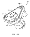
- the fitting may include relatively thin sections of material 314 between receptacles 204-1 through 204-4 (where receptacle 204-4 may be configured to couple to/seat a third bolt associated with the bearing housing).
- the sections 314 may be approximately two-tenths of an inch (0.2") (or approximately 5.1 millimeters) thick.
- the thickness may be between approximately one-eighth of an inch (0.125”) (or approximately 3.175 millimeters) and one-quarter of an inch (0.25”) (or approximately 6.35 millimeters).
- the fitting 204 may include a seal groove 334.
- the seal groove 334 may be substantially located around the perimeter of the fitting 204.
- the seal groove 334 may be used for coupling/seating the fitting 204 with respect to a surface of the bearing housing.
- the seal groove 334 may help to ensure that the fitting 204 maintains contact with bearing housing within a threshold amount and potential leakage past the bolts is contained by the seal.
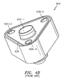
- FIGS. 4A-4B illustrate a fitting 404 in accordance with the prior art.
- the fitting 404 includes a receptacle 404-1 for accommodating a tube (e.g., the tube 202 of FIG. 2 ) and a seal groove 434 for coupling/seating the fitting 404 with respect to a bearing housing.
- Receptacles 404-2, 404-3, and 404-4 may be used to couple to/seat bolts associated with the bearing housing.
- the fitting 404 does not include thin sections of material 314 between receptacles 404-1 through 404-4. Instead, the fitting 404 is manufactured generally in the form of a solid, uniform block with material section 414 thickness of approximately eight-tenths of an inch (0.8") (or approximately 20.3 millimeters).
- the use of the thin material section 314 may enable the fitting 204 to maintain a more consistent sealing interface relative to the fitting 404 over temperature. This is reflected in the graphs 500 and 600 depicted in FIGS. 5-6 .
- a gap 504 (the value of which is reflected on the vertical or y-axis (in inches)) between the fitting 404 and the bearing housing approaches an "allowable gap” threshold 506 (within a margin of 7%) as a temperature gradient/difference (as reflected on the horizontal or x-axis) approaches, or slightly exceeds, 200 degrees Fahrenheit (or approximately 93 degrees Celsius).
- a gap 604 between the fitting 204 and the bearing housing maintains a margin of approximately 50% with respect to the same "allowable gap” threshold 506 of FIG. 5 .
- a seal may be placed on the outside of bolts that are used so that if leaking were to occur by gaps occurring around the location of bolts the fluid would be contained by the seal.
- the assembly 700 includes the tube 202 coupled to the fitting 404, and a bearing housing 710 coupled to the fitting 404.
- Bolts associated with the bearing housing 710 are inadequate to sufficiently reduce thermal distortion on the fitting 404, resulting in excessive gapping as reflected via the reference character 704.
- the gapping 704 may correspond to the gap 504 of FIG. 5 .
- FIG. 8 illustrates an assembly 800 in accordance with aspects of this disclosure.
- the assembly 800 incurs less, if any, gap 804 (where the gap 804 may correspond to the gap 604 of FIG. 6 ).
- This minimization/reduction in the gap may be a function of the stiffness of the bolts in comparison to the fitting 204 allowing for a quality seating of the fitting 204 to the bearing housing 710.
- FIG. 9 is a perspective view of the assembly 800 of FIG. 8 .
- two bolts denoted by reference characters 904-2 and 904-4 of the bearing housing 710 that are associated with the receptacles 204-2 and 204-4 are shown.
- this disclosure includes a fitting that maintains a higher-quality sealing contact/interface with a bearing housing.
- this enhanced sealing may be obtained by as a result of the use of thin material sections between receptacles (e.g., tube or bolt receptacles) of the fitting.
- the use of such thin material sections may enable a ratio of bolt loading to fitting stiffness to increase, allowing for more thermal compliance of the fitting to mating hardware associated with the bearing housing.
Landscapes
- Engineering & Computer Science (AREA)
- General Engineering & Computer Science (AREA)
- Mechanical Engineering (AREA)
- Chemical & Material Sciences (AREA)
- Combustion & Propulsion (AREA)
- Physics & Mathematics (AREA)
- Fluid Mechanics (AREA)
- Gasket Seals (AREA)
- Turbine Rotor Nozzle Sealing (AREA)
Abstract
Description
- On some aircraft engines, a tubing may couple a frame, such as a mid-turbine frame, to a housing, such as a bearing housing, for purposes of conveying fluids (e.g., lubricants, such as oil). The tubing may be exposed to relatively elevated temperatures (e.g., on the order of 1800 degrees Fahrenheit), due to being placed in a gas path. A fitting coupling the tubing to the bearing housing may subjected to a temperature of approximately 500 degrees Fahrenheit. The bearing housing may operate at a temperature of approximately 350 degrees Fahrenheit.
- One or more seals are used in connection with the engines in an effort to ensure that the fluids do not leak. However, due to the large temperature gradients/differences between the various components (e.g., the tubing, the fitting, the bearing housing) during operation, gaps between the mating parts that axial seals connect may develop. If a gap exceeds a threshold, the potential exists for a leak to develop.
- The following presents a simplified summary in order to provide a basic understanding of some aspects of the disclosure. The summary is not an extensive overview of the disclosure. It is neither intended to identify key or critical elements of the disclosure nor to delineate the scope of the disclosure. The following summary merely presents some concepts of the disclosure in a simplified form as a prelude to the description below.
- Aspects of the disclosure are directed to a fitting configured to couple a portion of a frame of a turbine and a bearing housing on an aircraft engine, comprising: a first receptacle configured to seat a tube that is configured to convey oil or air, and at least a second receptacle configured to seat a corresponding at least two bolts associated with the bearing housing, wherein the fitting comprises sections between the first receptacle and the at least a second receptacle that have a material thickness in a range of 3.175 millimeters and 6.35 millimeters. In some embodiments, the sections are approximately 5.1 millimeters thick thick. In some embodiments, the at least a second receptacle comprises three receptacles configured to seat three corresponding bolts. In some embodiments, the fitting further comprises a seal groove that is substantially located around the perimeter of the fitting.
- Aspects of the disclosure are directed to a system comprising: at least one tube, a bearing housing, and a fitting that includes: a first receptacle configured to seat the at least one tube, and at least a second receptacle configured to seat a corresponding at least one bolt associated with the bearing housing, wherein the fitting comprises sections between the first receptacle and the at least a second receptacle that have a material thickness in a range of 3.175 millimeters and 6.35 millimeters. In some embodiments, the sections are approximately 5.1 millimeters thick. In some embodiments, the at least a second receptacle comprises three receptacles configured to seat three corresponding bolts. In some embodiments, the system further comprises a seal groove that is substantially located around the perimeter of the fitting. In some embodiments, the at least one tube comprises at least two tubes. In some embodiments, a first of the at least two tubes is nested within a second of the at least two tubes. In some embodiments, the at least one tube is configured to convey oil or air.
- The present disclosure is illustrated by way of example and not limited in the accompanying figures in which like reference numerals indicate similar elements.
-
FIG. 1 illustrates an exemplary gas turbine engine in accordance with aspects of this disclosure. -
FIG. 2 illustrates an assembly for fluidly coupling a portion of a turbine frame to a bearing housing. -
FIG. 3A illustrates a first perspective view of a fitting ofFIG. 2 . -
FIG. 3B illustrates a second perspective view of the fitting ofFIG. 2 . -
FIG. 4A illustrates a first perspective view of a fitting in accordance with the prior art. -
FIG. 4B illustrates a second perspective view of the fitting ofFIG. 4A in accordance with the prior art. -
FIG. 5 illustrates a graph depicting a gap between the fitting ofFIGS. 4A-4B over a range of temperature gradients/differences in accordance with the prior art. -
FIG. 6 illustrates a graph depicting a gap between the fitting ofFIGS. 3A-3B over a range of temperature gradients/differences in accordance with aspects of this disclosure. -
FIG. 7 illustrates an assembly in accordance with the prior art. -
FIG. 8 illustrates an assembly in accordance with this disclosure. -
FIG. 9 illustrates a perspective view of the assembly ofFIG. 8 . - It is noted that various connections are set forth between elements in the following description and in the drawings (the contents of which are included in this disclosure by way of reference). It is noted that these connections are general and, unless specified otherwise, may be direct or indirect and that this specification is not intended to be limiting in this respect. A coupling between two or more entities may refer to a direct connection or an indirect connection. An indirect connection may incorporate one or more intervening entities.
- In accordance with various aspects of the disclosure, apparatuses, systems and methods are described for providing a tube for a lubrication or air system. The system may be used on an aircraft and may be incorporated in connection with one or more engines of the aircraft. Aspects of the disclosure are associated with a fitting of the tube. For example, aspects of the disclosure are associated with a profile of the fitting.
- Aspects of the disclosure may be applied in connection with an aircraft, or portion thereof. For example, aspects of the disclosure may be applied in connection with a gas turbine engine.
FIG. 1 is a side-sectional illustration of an exemplarygas turbine engine 10. Theengine 10 includes acompressor section 12, aturbine section 14 and one or more engine hot sections. The engine hot sections may include, for example, a first enginehot section 16 configured as a combustor section and a second enginehot section 18 configured as an augmentor section. Thecompressor section 12, the first enginehot section 16, theturbine section 14 and the second enginehot section 18 may be sequentially aligned along anaxial centerline 20 between a forwardengine airflow inlet 22 and an aftengine airflow exhaust 24. The second enginehot section 18 may include a first (e.g., annular, radial inner)duct case 26, a second (e.g., annular, radial outer)duct case 28, and one or morehot section vanes 30. - The
engine 10 is illustrative. Aspects of the disclosure may be applied in connection with other engine types or configurations. - Referring to
FIG. 2 , asystem assembly 200 in accordance with aspects of the disclosure is shown. Thesystem 200 includes atube 202 that may be used to convey fluids (e.g., oil). In some embodiments, thetube 202 may include multiple tubes; for example, thetube 202 may include a first, interior tube nested within a second, exterior tube. - The
tube 202 may couple to afirst fitting 204. The fitting 204 may include one or more receptacles. A first receptacle 204-1 may be configured to couple to/seat thetube 202. A second receptacle 204-2 may be configured to couple to/seat a first bolt associated with a bearing housing (not shown inFIG. 2 , but shown and described below in connection withFIGS. 7-8 ). A third receptacle 204-3 may be configured to couple to/seat a second bolt associated with the bearing housing. Any number of bolts or receptacles may be used in some embodiments. - The
tube 202 may couple to a (portion of a) frame or support structure associated with a turbine (e.g.,turbine section 14 ofFIG. 1 ) towards anend 206 of thetube 202. - Referring to
FIGS. 3A-3B (collectively referred to asFIG. 3 ), a closer view of the fitting 204 is shown. As shown inFIG. 3 , the fitting may include relatively thin sections ofmaterial 314 between receptacles 204-1 through 204-4 (where receptacle 204-4 may be configured to couple to/seat a third bolt associated with the bearing housing). In some embodiments, thesections 314 may be approximately two-tenths of an inch (0.2") (or approximately 5.1 millimeters) thick. In some embodiments, the thickness may be between approximately one-eighth of an inch (0.125") (or approximately 3.175 millimeters) and one-quarter of an inch (0.25") (or approximately 6.35 millimeters). - As shown in
FIG. 3 , the fitting 204 may include aseal groove 334. Theseal groove 334 may be substantially located around the perimeter of the fitting 204. Theseal groove 334 may be used for coupling/seating the fitting 204 with respect to a surface of the bearing housing. Theseal groove 334 may help to ensure that the fitting 204 maintains contact with bearing housing within a threshold amount and potential leakage past the bolts is contained by the seal. - In contrast to
FIG. 3 ,FIGS. 4A-4B (collectively referred to asFIG. 4 ) illustrate a fitting 404 in accordance with the prior art. The fitting 404 includes a receptacle 404-1 for accommodating a tube (e.g., thetube 202 ofFIG. 2 ) and aseal groove 434 for coupling/seating the fitting 404 with respect to a bearing housing. Receptacles 404-2, 404-3, and 404-4 may be used to couple to/seat bolts associated with the bearing housing. - Unlike the fitting 204 of
FIGS. 2-3 , the fitting 404 does not include thin sections ofmaterial 314 between receptacles 404-1 through 404-4. Instead, the fitting 404 is manufactured generally in the form of a solid, uniform block withmaterial section 414 thickness of approximately eight-tenths of an inch (0.8") (or approximately 20.3 millimeters). - The use of the
thin material section 314 may enable the fitting 204 to maintain a more consistent sealing interface relative to the fitting 404 over temperature. This is reflected in thegraphs FIGS. 5-6 . InFIG. 5 , which is indicative of the use of the fitting 404, a gap 504 (the value of which is reflected on the vertical or y-axis (in inches)) between the fitting 404 and the bearing housing approaches an "allowable gap" threshold 506 (within a margin of 7%) as a temperature gradient/difference (as reflected on the horizontal or x-axis) approaches, or slightly exceeds, 200 degrees Fahrenheit (or approximately 93 degrees Celsius). InFIG. 6 , which is indicative of the use of the fitting 204, agap 604 between the fitting 204 and the bearing housing maintains a margin of approximately 50% with respect to the same "allowable gap"threshold 506 ofFIG. 5 . - In accordance with aspects of this disclosure, and based on a comparison of
FIG. 3 relative toFIG. 4 , a seal may be placed on the outside of bolts that are used so that if leaking were to occur by gaps occurring around the location of bolts the fluid would be contained by the seal. - Referring now to
FIG. 7 , anassembly 700 in accordance with the prior art is shown. Theassembly 700 includes thetube 202 coupled to the fitting 404, and a bearinghousing 710 coupled to the fitting 404. Bolts associated with the bearinghousing 710 are inadequate to sufficiently reduce thermal distortion on the fitting 404, resulting in excessive gapping as reflected via thereference character 704. The gapping 704 may correspond to thegap 504 ofFIG. 5 . -
FIG. 8 illustrates anassembly 800 in accordance with aspects of this disclosure. In contrast to theassembly 700/gap 704, theassembly 800 incurs less, if any, gap 804 (where thegap 804 may correspond to thegap 604 ofFIG. 6 ). This minimization/reduction in the gap may be a function of the stiffness of the bolts in comparison to the fitting 204 allowing for a quality seating of the fitting 204 to the bearinghousing 710. -
FIG. 9 is a perspective view of theassembly 800 ofFIG. 8 . In this perspective view, two bolts (denoted by reference characters 904-2 and 904-4) of the bearinghousing 710 that are associated with the receptacles 204-2 and 204-4 are shown. - Technical effects and benefits of this disclosure include a fitting that maintains a higher-quality sealing contact/interface with a bearing housing. In accordance with aspects of this disclosure, this enhanced sealing may be obtained by as a result of the use of thin material sections between receptacles (e.g., tube or bolt receptacles) of the fitting. The use of such thin material sections may enable a ratio of bolt loading to fitting stiffness to increase, allowing for more thermal compliance of the fitting to mating hardware associated with the bearing housing.
- Aspects of the disclosure have been described in terms of illustrative embodiments thereof. Numerous other embodiments, modifications, and variations within the scope of the appended claims will occur to persons of ordinary skill in the art from a review of this disclosure. For example, one of ordinary skill in the art will appreciate that the steps described in conjunction with the illustrative figures may be performed in other than the recited order, and that one or more steps illustrated may be optional in accordance with aspects of the disclosure. One or more features described in connection with a first embodiment may be combined with one or more features of one or more additional embodiments.
Claims (12)
- A fitting configured to couple a portion of a frame of a turbine and a bearing housing on an aircraft engine, comprising:a first receptacle (204-1) configured to seat a tube (202) that is configured to convey fluid; andat least a second receptacle (204-2) configured to seat a corresponding at least two bolts associated with the bearing housing,wherein the fitting comprises sections between the first receptacle and the at least a second receptacle that have a material thickness in a range of 3.175 millimeters and 6.35 millimeters.
- The fitting of claim 1, wherein the sections are approximately 5.1 millimeters thick.
- The fitting of claim 1 or 2, wherein the at least a second receptacle (204-2) comprises three receptacles configured to seat three corresponding bolts.
- The fitting of claim 1, 2 or 3, further comprising:a seal groove (334) that is substantially located around the perimeter of the fitting.
- A system comprising:at least one tube (202);a bearing housing; anda fitting that includes:a first receptacle (204-1) configured to seat the at least one tube; andat least a second receptacle (204-2) configured to seat a corresponding at least one bolt associated with the bearing housing,wherein the fitting comprises sections between the first receptacle (204-1) and the at least a second receptacle (204-2) that have a material thickness in a range of 3.175 millimeters and 6.35 millimeters.
- The system of claim 5, wherein the sections are approximately 5.1 millimeters thick.
- The system of claim 5 or 6, wherein the at least a second receptacle (204-2) comprises three receptacles configured to seat three corresponding bolts.
- The system of claim 5, 6 or 7, further comprising:a seal groove (334) that is substantially located around the perimeter of the fitting.
- A system comprising:at least one tube (202),a bearing housing;a fitting as claimed in any of claims 1-4.
- The system of any of claims 5-9, wherein the at least one tube comprises at least two tubes.
- The system of claim 10, wherein a first of the at least two tubes is nested within a second of the at least two tubes.
- The system of any of claims 5-11, wherein the at least one tube is configured to convey oil or air.
Applications Claiming Priority (1)
| Application Number | Priority Date | Filing Date | Title |
|---|---|---|---|
| US14/618,639 US10161309B2 (en) | 2015-02-10 | 2015-02-10 | Thermally compliant fitting for high temperature tube applications |
Publications (2)
| Publication Number | Publication Date |
|---|---|
| EP3056682A1 true EP3056682A1 (en) | 2016-08-17 |
| EP3056682B1 EP3056682B1 (en) | 2021-11-24 |
Family
ID=55527734
Family Applications (1)
| Application Number | Title | Priority Date | Filing Date |
|---|---|---|---|
| EP16155091.8A Active EP3056682B1 (en) | 2015-02-10 | 2016-02-10 | Thermally compliant fitting for high temperature tube applications |
Country Status (2)
| Country | Link |
|---|---|
| US (1) | US10161309B2 (en) |
| EP (1) | EP3056682B1 (en) |
Families Citing this family (2)
| Publication number | Priority date | Publication date | Assignee | Title |
|---|---|---|---|---|
| US20190112946A1 (en) * | 2017-10-13 | 2019-04-18 | United Technologies Corporation | Double wall service tube with annular airflow passage |
| US11085313B2 (en) * | 2019-11-22 | 2021-08-10 | Raytheon Technologies Corporation | System and method for transporting lubricant through a vane |
Citations (5)
| Publication number | Priority date | Publication date | Assignee | Title |
|---|---|---|---|---|
| US5272869A (en) * | 1992-12-10 | 1993-12-28 | General Electric Company | Turbine frame |
| US5593279A (en) * | 1994-09-07 | 1997-01-14 | Kayaba Industry Co., Ltd. | Suction connector for pump |
| US20040026922A1 (en) * | 2002-08-09 | 2004-02-12 | Carns James A. | Shrouded fluid-conducting apparatus |
| US20140030088A1 (en) * | 2012-07-30 | 2014-01-30 | United Technologies Corporation | Forward compartment service system for a geared architecture gas turbine engine |
| WO2014051658A1 (en) * | 2012-09-26 | 2014-04-03 | United Technologies Corporation | Seal assembly for a static structure of a gas turbine engine |
Family Cites Families (11)
| Publication number | Priority date | Publication date | Assignee | Title |
|---|---|---|---|---|
| US2804280A (en) | 1951-03-20 | 1957-08-27 | Gen Motors Corp | Turbine bearing lubrication system |
| US3012252A (en) * | 1960-10-11 | 1961-12-12 | Thomas W Kern | Closet bowl floor connector |
| US4626001A (en) | 1984-04-16 | 1986-12-02 | The Deutsch Company Metal Components Division | Fluid fitting with high temperature capabilities |
| GB8905894D0 (en) * | 1989-03-15 | 1989-04-26 | Rolls Royce Plc | Fluid-tight joints |
| US5108045A (en) | 1990-04-25 | 1992-04-28 | Law Thomas R | Engine mounting assembly |
| US5799629A (en) | 1993-08-27 | 1998-09-01 | Lowi, Jr.; Alvin | Adiabatic, two-stroke cycle engine having external piston rod alignment |
| US6070910A (en) * | 1997-10-17 | 2000-06-06 | James Bruno | Push-in closet flange |
| US6467820B1 (en) * | 1998-10-23 | 2002-10-22 | David E. Albrecht | High-pressure fluid-flow system having compact two-bolt and four-bolt flanged and modular connectors |
| GB9908845D0 (en) | 1999-04-19 | 1999-06-16 | Seneca Tech Ltd | Inverted engine configuration |
| JP4287125B2 (en) * | 2002-02-18 | 2009-07-01 | 三桜工業株式会社 | Piping connection structure to flange |
| WO2008154167A1 (en) * | 2007-06-06 | 2008-12-18 | Pridgeon & Clay, Inc. | Pipe compression joint |
-
2015
- 2015-02-10 US US14/618,639 patent/US10161309B2/en active Active
-
2016
- 2016-02-10 EP EP16155091.8A patent/EP3056682B1/en active Active
Patent Citations (5)
| Publication number | Priority date | Publication date | Assignee | Title |
|---|---|---|---|---|
| US5272869A (en) * | 1992-12-10 | 1993-12-28 | General Electric Company | Turbine frame |
| US5593279A (en) * | 1994-09-07 | 1997-01-14 | Kayaba Industry Co., Ltd. | Suction connector for pump |
| US20040026922A1 (en) * | 2002-08-09 | 2004-02-12 | Carns James A. | Shrouded fluid-conducting apparatus |
| US20140030088A1 (en) * | 2012-07-30 | 2014-01-30 | United Technologies Corporation | Forward compartment service system for a geared architecture gas turbine engine |
| WO2014051658A1 (en) * | 2012-09-26 | 2014-04-03 | United Technologies Corporation | Seal assembly for a static structure of a gas turbine engine |
Also Published As
| Publication number | Publication date |
|---|---|
| US20160230910A1 (en) | 2016-08-11 |
| EP3056682B1 (en) | 2021-11-24 |
| US10161309B2 (en) | 2018-12-25 |
Similar Documents
| Publication | Publication Date | Title |
|---|---|---|
| US9039358B2 (en) | Replaceable blade outer air seal design | |
| CN104254671B (en) | Semi-sleeve metal seal integral with a tube | |
| US10502094B2 (en) | Bearing compartment sealing system with passive cooling | |
| CN103109044B (en) | Turbine jet engine ventilation duct, the method for this ventilation duct is installed and is provided with the turbine jet engine of this ventilation duct | |
| CN106687675B (en) | Sealing structure | |
| US8490409B2 (en) | Bleed air transfer tube | |
| CN100472046C (en) | Connection between the cooling air chamber and the guide of a gas turbine engine | |
| EP2570612A1 (en) | Turbomachine secondary seal assembly | |
| US20160097302A1 (en) | Turbine bearing and seal assembly for a turbocharger | |
| EP3056682B1 (en) | Thermally compliant fitting for high temperature tube applications | |
| US10844739B2 (en) | Platforms with leading edge features | |
| EP3048344A2 (en) | Seal housing pre-taper | |
| US9212756B2 (en) | High pressure check valve flange joint | |
| CA2955815C (en) | Magnetic seal system with internal cooling | |
| US20160208926A1 (en) | Splined honeycomb seals | |
| GB2555632A (en) | Self-sealing impingement cooling tube for a turbine vane | |
| US10415411B2 (en) | Splined dog-bone seal | |
| US11719159B2 (en) | Transfer tube assembly | |
| US10344983B2 (en) | Assembly of tube and structure crossing multi chambers | |
| US11280208B2 (en) | Labyrinth seal assembly | |
| CN205477769U (en) | A sealing component for use with turbine engine | |
| EP3054114A1 (en) | Forward flange and cone wall stress deflection management |
Legal Events
| Date | Code | Title | Description |
|---|---|---|---|
| PUAI | Public reference made under article 153(3) epc to a published international application that has entered the european phase |
Free format text: ORIGINAL CODE: 0009012 |
|
| AK | Designated contracting states |
Kind code of ref document: A1 Designated state(s): AL AT BE BG CH CY CZ DE DK EE ES FI FR GB GR HR HU IE IS IT LI LT LU LV MC MK MT NL NO PL PT RO RS SE SI SK SM TR |
|
| AX | Request for extension of the european patent |
Extension state: BA ME |
|
| RAP1 | Party data changed (applicant data changed or rights of an application transferred) |
Owner name: UNITED TECHNOLOGIES CORPORATION |
|
| STAA | Information on the status of an ep patent application or granted ep patent |
Free format text: STATUS: REQUEST FOR EXAMINATION WAS MADE |
|
| 17P | Request for examination filed |
Effective date: 20170215 |
|
| RBV | Designated contracting states (corrected) |
Designated state(s): AL AT BE BG CH CY CZ DE DK EE ES FI FR GB GR HR HU IE IS IT LI LT LU LV MC MK MT NL NO PL PT RO RS SE SI SK SM TR |
|
| STAA | Information on the status of an ep patent application or granted ep patent |
Free format text: STATUS: EXAMINATION IS IN PROGRESS |
|
| 17Q | First examination report despatched |
Effective date: 20190729 |
|
| RAP1 | Party data changed (applicant data changed or rights of an application transferred) |
Owner name: RAYTHEON TECHNOLOGIES CORPORATION |
|
| GRAP | Despatch of communication of intention to grant a patent |
Free format text: ORIGINAL CODE: EPIDOSNIGR1 |
|
| STAA | Information on the status of an ep patent application or granted ep patent |
Free format text: STATUS: GRANT OF PATENT IS INTENDED |
|
| INTG | Intention to grant announced |
Effective date: 20210615 |
|
| GRAS | Grant fee paid |
Free format text: ORIGINAL CODE: EPIDOSNIGR3 |
|
| GRAA | (expected) grant |
Free format text: ORIGINAL CODE: 0009210 |
|
| STAA | Information on the status of an ep patent application or granted ep patent |
Free format text: STATUS: THE PATENT HAS BEEN GRANTED |
|
| AK | Designated contracting states |
Kind code of ref document: B1 Designated state(s): AL AT BE BG CH CY CZ DE DK EE ES FI FR GB GR HR HU IE IS IT LI LT LU LV MC MK MT NL NO PL PT RO RS SE SI SK SM TR |
|
| REG | Reference to a national code |
Ref country code: GB Ref legal event code: FG4D |
|
| REG | Reference to a national code |
Ref country code: AT Ref legal event code: REF Ref document number: 1450016 Country of ref document: AT Kind code of ref document: T Effective date: 20211215 |
|
| REG | Reference to a national code |
Ref country code: DE Ref legal event code: R096 Ref document number: 602016066499 Country of ref document: DE |
|
| REG | Reference to a national code |
Ref country code: IE Ref legal event code: FG4D |
|
| REG | Reference to a national code |
Ref country code: LT Ref legal event code: MG9D |
|
| REG | Reference to a national code |
Ref country code: NL Ref legal event code: MP Effective date: 20211124 |
|
| REG | Reference to a national code |
Ref country code: AT Ref legal event code: MK05 Ref document number: 1450016 Country of ref document: AT Kind code of ref document: T Effective date: 20211124 |
|
| PG25 | Lapsed in a contracting state [announced via postgrant information from national office to epo] |
Ref country code: RS Free format text: LAPSE BECAUSE OF FAILURE TO SUBMIT A TRANSLATION OF THE DESCRIPTION OR TO PAY THE FEE WITHIN THE PRESCRIBED TIME-LIMIT Effective date: 20211124 Ref country code: LT Free format text: LAPSE BECAUSE OF FAILURE TO SUBMIT A TRANSLATION OF THE DESCRIPTION OR TO PAY THE FEE WITHIN THE PRESCRIBED TIME-LIMIT Effective date: 20211124 Ref country code: FI Free format text: LAPSE BECAUSE OF FAILURE TO SUBMIT A TRANSLATION OF THE DESCRIPTION OR TO PAY THE FEE WITHIN THE PRESCRIBED TIME-LIMIT Effective date: 20211124 Ref country code: BG Free format text: LAPSE BECAUSE OF FAILURE TO SUBMIT A TRANSLATION OF THE DESCRIPTION OR TO PAY THE FEE WITHIN THE PRESCRIBED TIME-LIMIT Effective date: 20220224 Ref country code: AT Free format text: LAPSE BECAUSE OF FAILURE TO SUBMIT A TRANSLATION OF THE DESCRIPTION OR TO PAY THE FEE WITHIN THE PRESCRIBED TIME-LIMIT Effective date: 20211124 |
|
| PG25 | Lapsed in a contracting state [announced via postgrant information from national office to epo] |
Ref country code: IS Free format text: LAPSE BECAUSE OF FAILURE TO SUBMIT A TRANSLATION OF THE DESCRIPTION OR TO PAY THE FEE WITHIN THE PRESCRIBED TIME-LIMIT Effective date: 20220324 Ref country code: SE Free format text: LAPSE BECAUSE OF FAILURE TO SUBMIT A TRANSLATION OF THE DESCRIPTION OR TO PAY THE FEE WITHIN THE PRESCRIBED TIME-LIMIT Effective date: 20211124 Ref country code: PT Free format text: LAPSE BECAUSE OF FAILURE TO SUBMIT A TRANSLATION OF THE DESCRIPTION OR TO PAY THE FEE WITHIN THE PRESCRIBED TIME-LIMIT Effective date: 20220324 Ref country code: PL Free format text: LAPSE BECAUSE OF FAILURE TO SUBMIT A TRANSLATION OF THE DESCRIPTION OR TO PAY THE FEE WITHIN THE PRESCRIBED TIME-LIMIT Effective date: 20211124 Ref country code: NO Free format text: LAPSE BECAUSE OF FAILURE TO SUBMIT A TRANSLATION OF THE DESCRIPTION OR TO PAY THE FEE WITHIN THE PRESCRIBED TIME-LIMIT Effective date: 20220224 Ref country code: NL Free format text: LAPSE BECAUSE OF FAILURE TO SUBMIT A TRANSLATION OF THE DESCRIPTION OR TO PAY THE FEE WITHIN THE PRESCRIBED TIME-LIMIT Effective date: 20211124 Ref country code: LV Free format text: LAPSE BECAUSE OF FAILURE TO SUBMIT A TRANSLATION OF THE DESCRIPTION OR TO PAY THE FEE WITHIN THE PRESCRIBED TIME-LIMIT Effective date: 20211124 Ref country code: HR Free format text: LAPSE BECAUSE OF FAILURE TO SUBMIT A TRANSLATION OF THE DESCRIPTION OR TO PAY THE FEE WITHIN THE PRESCRIBED TIME-LIMIT Effective date: 20211124 Ref country code: GR Free format text: LAPSE BECAUSE OF FAILURE TO SUBMIT A TRANSLATION OF THE DESCRIPTION OR TO PAY THE FEE WITHIN THE PRESCRIBED TIME-LIMIT Effective date: 20220225 Ref country code: ES Free format text: LAPSE BECAUSE OF FAILURE TO SUBMIT A TRANSLATION OF THE DESCRIPTION OR TO PAY THE FEE WITHIN THE PRESCRIBED TIME-LIMIT Effective date: 20211124 |
|
| PG25 | Lapsed in a contracting state [announced via postgrant information from national office to epo] |
Ref country code: SM Free format text: LAPSE BECAUSE OF FAILURE TO SUBMIT A TRANSLATION OF THE DESCRIPTION OR TO PAY THE FEE WITHIN THE PRESCRIBED TIME-LIMIT Effective date: 20211124 Ref country code: SK Free format text: LAPSE BECAUSE OF FAILURE TO SUBMIT A TRANSLATION OF THE DESCRIPTION OR TO PAY THE FEE WITHIN THE PRESCRIBED TIME-LIMIT Effective date: 20211124 Ref country code: RO Free format text: LAPSE BECAUSE OF FAILURE TO SUBMIT A TRANSLATION OF THE DESCRIPTION OR TO PAY THE FEE WITHIN THE PRESCRIBED TIME-LIMIT Effective date: 20211124 Ref country code: EE Free format text: LAPSE BECAUSE OF FAILURE TO SUBMIT A TRANSLATION OF THE DESCRIPTION OR TO PAY THE FEE WITHIN THE PRESCRIBED TIME-LIMIT Effective date: 20211124 Ref country code: DK Free format text: LAPSE BECAUSE OF FAILURE TO SUBMIT A TRANSLATION OF THE DESCRIPTION OR TO PAY THE FEE WITHIN THE PRESCRIBED TIME-LIMIT Effective date: 20211124 Ref country code: CZ Free format text: LAPSE BECAUSE OF FAILURE TO SUBMIT A TRANSLATION OF THE DESCRIPTION OR TO PAY THE FEE WITHIN THE PRESCRIBED TIME-LIMIT Effective date: 20211124 |
|
| REG | Reference to a national code |
Ref country code: DE Ref legal event code: R097 Ref document number: 602016066499 Country of ref document: DE |
|
| PG25 | Lapsed in a contracting state [announced via postgrant information from national office to epo] |
Ref country code: MC Free format text: LAPSE BECAUSE OF FAILURE TO SUBMIT A TRANSLATION OF THE DESCRIPTION OR TO PAY THE FEE WITHIN THE PRESCRIBED TIME-LIMIT Effective date: 20211124 |
|
| PLBE | No opposition filed within time limit |
Free format text: ORIGINAL CODE: 0009261 |
|
| STAA | Information on the status of an ep patent application or granted ep patent |
Free format text: STATUS: NO OPPOSITION FILED WITHIN TIME LIMIT |
|
| REG | Reference to a national code |
Ref country code: CH Ref legal event code: PL |
|
| REG | Reference to a national code |
Ref country code: BE Ref legal event code: MM Effective date: 20220228 |
|
| PG25 | Lapsed in a contracting state [announced via postgrant information from national office to epo] |
Ref country code: LU Free format text: LAPSE BECAUSE OF NON-PAYMENT OF DUE FEES Effective date: 20220210 Ref country code: AL Free format text: LAPSE BECAUSE OF FAILURE TO SUBMIT A TRANSLATION OF THE DESCRIPTION OR TO PAY THE FEE WITHIN THE PRESCRIBED TIME-LIMIT Effective date: 20211124 |
|
| 26N | No opposition filed |
Effective date: 20220825 |
|
| PG25 | Lapsed in a contracting state [announced via postgrant information from national office to epo] |
Ref country code: SI Free format text: LAPSE BECAUSE OF FAILURE TO SUBMIT A TRANSLATION OF THE DESCRIPTION OR TO PAY THE FEE WITHIN THE PRESCRIBED TIME-LIMIT Effective date: 20211124 |
|
| PG25 | Lapsed in a contracting state [announced via postgrant information from national office to epo] |
Ref country code: LI Free format text: LAPSE BECAUSE OF NON-PAYMENT OF DUE FEES Effective date: 20220228 Ref country code: IE Free format text: LAPSE BECAUSE OF NON-PAYMENT OF DUE FEES Effective date: 20220210 Ref country code: CH Free format text: LAPSE BECAUSE OF NON-PAYMENT OF DUE FEES Effective date: 20220228 |
|
| PG25 | Lapsed in a contracting state [announced via postgrant information from national office to epo] |
Ref country code: BE Free format text: LAPSE BECAUSE OF NON-PAYMENT OF DUE FEES Effective date: 20220228 |
|
| PG25 | Lapsed in a contracting state [announced via postgrant information from national office to epo] |
Ref country code: IT Free format text: LAPSE BECAUSE OF FAILURE TO SUBMIT A TRANSLATION OF THE DESCRIPTION OR TO PAY THE FEE WITHIN THE PRESCRIBED TIME-LIMIT Effective date: 20211124 |
|
| P01 | Opt-out of the competence of the unified patent court (upc) registered |
Effective date: 20230520 |
|
| PG25 | Lapsed in a contracting state [announced via postgrant information from national office to epo] |
Ref country code: HU Free format text: LAPSE BECAUSE OF FAILURE TO SUBMIT A TRANSLATION OF THE DESCRIPTION OR TO PAY THE FEE WITHIN THE PRESCRIBED TIME-LIMIT; INVALID AB INITIO Effective date: 20160210 |
|
| PG25 | Lapsed in a contracting state [announced via postgrant information from national office to epo] |
Ref country code: MK Free format text: LAPSE BECAUSE OF FAILURE TO SUBMIT A TRANSLATION OF THE DESCRIPTION OR TO PAY THE FEE WITHIN THE PRESCRIBED TIME-LIMIT Effective date: 20211124 Ref country code: CY Free format text: LAPSE BECAUSE OF FAILURE TO SUBMIT A TRANSLATION OF THE DESCRIPTION OR TO PAY THE FEE WITHIN THE PRESCRIBED TIME-LIMIT Effective date: 20211124 |
|
| PG25 | Lapsed in a contracting state [announced via postgrant information from national office to epo] |
Ref country code: MT Free format text: LAPSE BECAUSE OF FAILURE TO SUBMIT A TRANSLATION OF THE DESCRIPTION OR TO PAY THE FEE WITHIN THE PRESCRIBED TIME-LIMIT Effective date: 20211124 |
|
| REG | Reference to a national code |
Ref country code: DE Ref legal event code: R081 Ref document number: 602016066499 Country of ref document: DE Owner name: RTX CORPORATION (N.D.GES.D. STAATES DELAWARE),, US Free format text: FORMER OWNER: RAYTHEON TECHNOLOGIES CORPORATION, FARMINGTON, CT, US |
|
| PG25 | Lapsed in a contracting state [announced via postgrant information from national office to epo] |
Ref country code: TR Free format text: LAPSE BECAUSE OF FAILURE TO SUBMIT A TRANSLATION OF THE DESCRIPTION OR TO PAY THE FEE WITHIN THE PRESCRIBED TIME-LIMIT Effective date: 20211124 |
|
| PGFP | Annual fee paid to national office [announced via postgrant information from national office to epo] |
Ref country code: GB Payment date: 20260121 Year of fee payment: 11 |
|
| PGFP | Annual fee paid to national office [announced via postgrant information from national office to epo] |
Ref country code: DE Payment date: 20260121 Year of fee payment: 11 |
|
| PGFP | Annual fee paid to national office [announced via postgrant information from national office to epo] |
Ref country code: FR Payment date: 20260121 Year of fee payment: 11 |