EP3056670A1 - Turbomachine component having cooling channels with angled pedestals - Google Patents
Turbomachine component having cooling channels with angled pedestals Download PDFInfo
- Publication number
- EP3056670A1 EP3056670A1 EP15199495.1A EP15199495A EP3056670A1 EP 3056670 A1 EP3056670 A1 EP 3056670A1 EP 15199495 A EP15199495 A EP 15199495A EP 3056670 A1 EP3056670 A1 EP 3056670A1
- Authority
- EP
- European Patent Office
- Prior art keywords
- turbomachine component
- turbomachine
- angled
- cooling channel
- pedestal
- Prior art date
- Legal status (The legal status is an assumption and is not a legal conclusion. Google has not performed a legal analysis and makes no representation as to the accuracy of the status listed.)
- Withdrawn
Links
- 238000001816 cooling Methods 0.000 title claims abstract description 107
- NJPPVKZQTLUDBO-UHFFFAOYSA-N novaluron Chemical compound C1=C(Cl)C(OC(F)(F)C(OC(F)(F)F)F)=CC=C1NC(=O)NC(=O)C1=C(F)C=CC=C1F NJPPVKZQTLUDBO-UHFFFAOYSA-N 0.000 claims abstract description 51
- 238000000034 method Methods 0.000 claims abstract description 18
- 238000004891 communication Methods 0.000 claims abstract description 13
- 239000012530 fluid Substances 0.000 claims abstract description 12
- 238000004519 manufacturing process Methods 0.000 claims description 14
- 238000003754 machining Methods 0.000 claims description 5
- 238000007493 shaping process Methods 0.000 claims description 5
- 239000000446 fuel Substances 0.000 description 4
- 238000012986 modification Methods 0.000 description 2
- 230000004048 modification Effects 0.000 description 2
- 230000009467 reduction Effects 0.000 description 2
- 230000003068 static effect Effects 0.000 description 2
- 238000012546 transfer Methods 0.000 description 2
- 238000005266 casting Methods 0.000 description 1
- 230000008859 change Effects 0.000 description 1
- 230000006835 compression Effects 0.000 description 1
- 238000007906 compression Methods 0.000 description 1
- 238000007796 conventional method Methods 0.000 description 1
- 238000012937 correction Methods 0.000 description 1
- 230000007246 mechanism Effects 0.000 description 1
- 230000004044 response Effects 0.000 description 1
Images




Classifications
-
- F—MECHANICAL ENGINEERING; LIGHTING; HEATING; WEAPONS; BLASTING
- F01—MACHINES OR ENGINES IN GENERAL; ENGINE PLANTS IN GENERAL; STEAM ENGINES
- F01D—NON-POSITIVE DISPLACEMENT MACHINES OR ENGINES, e.g. STEAM TURBINES
- F01D5/00—Blades; Blade-carrying members; Heating, heat-insulating, cooling or antivibration means on the blades or the members
- F01D5/12—Blades
- F01D5/14—Form or construction
- F01D5/18—Hollow blades, i.e. blades with cooling or heating channels or cavities; Heating, heat-insulating or cooling means on blades
- F01D5/187—Convection cooling
-
- B—PERFORMING OPERATIONS; TRANSPORTING
- B23—MACHINE TOOLS; METAL-WORKING NOT OTHERWISE PROVIDED FOR
- B23H—WORKING OF METAL BY THE ACTION OF A HIGH CONCENTRATION OF ELECTRIC CURRENT ON A WORKPIECE USING AN ELECTRODE WHICH TAKES THE PLACE OF A TOOL; SUCH WORKING COMBINED WITH OTHER FORMS OF WORKING OF METAL
- B23H9/00—Machining specially adapted for treating particular metal objects or for obtaining special effects or results on metal objects
- B23H9/10—Working turbine blades or nozzles
-
- F—MECHANICAL ENGINEERING; LIGHTING; HEATING; WEAPONS; BLASTING
- F01—MACHINES OR ENGINES IN GENERAL; ENGINE PLANTS IN GENERAL; STEAM ENGINES
- F01D—NON-POSITIVE DISPLACEMENT MACHINES OR ENGINES, e.g. STEAM TURBINES
- F01D11/00—Preventing or minimising internal leakage of working-fluid, e.g. between stages
- F01D11/08—Preventing or minimising internal leakage of working-fluid, e.g. between stages for sealing space between rotor blade tips and stator
-
- F—MECHANICAL ENGINEERING; LIGHTING; HEATING; WEAPONS; BLASTING
- F01—MACHINES OR ENGINES IN GENERAL; ENGINE PLANTS IN GENERAL; STEAM ENGINES
- F01D—NON-POSITIVE DISPLACEMENT MACHINES OR ENGINES, e.g. STEAM TURBINES
- F01D25/00—Component parts, details, or accessories, not provided for in, or of interest apart from, other groups
- F01D25/08—Cooling; Heating; Heat-insulation
- F01D25/12—Cooling
-
- F—MECHANICAL ENGINEERING; LIGHTING; HEATING; WEAPONS; BLASTING
- F01—MACHINES OR ENGINES IN GENERAL; ENGINE PLANTS IN GENERAL; STEAM ENGINES
- F01D—NON-POSITIVE DISPLACEMENT MACHINES OR ENGINES, e.g. STEAM TURBINES
- F01D9/00—Stators
- F01D9/02—Nozzles; Nozzle boxes; Stator blades; Guide conduits, e.g. individual nozzles
- F01D9/04—Nozzles; Nozzle boxes; Stator blades; Guide conduits, e.g. individual nozzles forming ring or sector
- F01D9/041—Nozzles; Nozzle boxes; Stator blades; Guide conduits, e.g. individual nozzles forming ring or sector using blades
-
- F—MECHANICAL ENGINEERING; LIGHTING; HEATING; WEAPONS; BLASTING
- F01—MACHINES OR ENGINES IN GENERAL; ENGINE PLANTS IN GENERAL; STEAM ENGINES
- F01D—NON-POSITIVE DISPLACEMENT MACHINES OR ENGINES, e.g. STEAM TURBINES
- F01D9/00—Stators
- F01D9/06—Fluid supply conduits to nozzles or the like
- F01D9/065—Fluid supply or removal conduits traversing the working fluid flow, e.g. for lubrication-, cooling-, or sealing fluids
-
- F—MECHANICAL ENGINEERING; LIGHTING; HEATING; WEAPONS; BLASTING
- F02—COMBUSTION ENGINES; HOT-GAS OR COMBUSTION-PRODUCT ENGINE PLANTS
- F02C—GAS-TURBINE PLANTS; AIR INTAKES FOR JET-PROPULSION PLANTS; CONTROLLING FUEL SUPPLY IN AIR-BREATHING JET-PROPULSION PLANTS
- F02C7/00—Features, components parts, details or accessories, not provided for in, or of interest apart form groups F02C1/00 - F02C6/00; Air intakes for jet-propulsion plants
- F02C7/12—Cooling of plants
- F02C7/16—Cooling of plants characterised by cooling medium
- F02C7/18—Cooling of plants characterised by cooling medium the medium being gaseous, e.g. air
-
- F—MECHANICAL ENGINEERING; LIGHTING; HEATING; WEAPONS; BLASTING
- F23—COMBUSTION APPARATUS; COMBUSTION PROCESSES
- F23R—GENERATING COMBUSTION PRODUCTS OF HIGH PRESSURE OR HIGH VELOCITY, e.g. GAS-TURBINE COMBUSTION CHAMBERS
- F23R3/00—Continuous combustion chambers using liquid or gaseous fuel
- F23R3/002—Wall structures
-
- B—PERFORMING OPERATIONS; TRANSPORTING
- B23—MACHINE TOOLS; METAL-WORKING NOT OTHERWISE PROVIDED FOR
- B23K—SOLDERING OR UNSOLDERING; WELDING; CLADDING OR PLATING BY SOLDERING OR WELDING; CUTTING BY APPLYING HEAT LOCALLY, e.g. FLAME CUTTING; WORKING BY LASER BEAM
- B23K2101/00—Articles made by soldering, welding or cutting
- B23K2101/001—Turbines
-
- F—MECHANICAL ENGINEERING; LIGHTING; HEATING; WEAPONS; BLASTING
- F05—INDEXING SCHEMES RELATING TO ENGINES OR PUMPS IN VARIOUS SUBCLASSES OF CLASSES F01-F04
- F05D—INDEXING SCHEME FOR ASPECTS RELATING TO NON-POSITIVE-DISPLACEMENT MACHINES OR ENGINES, GAS-TURBINES OR JET-PROPULSION PLANTS
- F05D2220/00—Application
- F05D2220/30—Application in turbines
-
- F—MECHANICAL ENGINEERING; LIGHTING; HEATING; WEAPONS; BLASTING
- F05—INDEXING SCHEMES RELATING TO ENGINES OR PUMPS IN VARIOUS SUBCLASSES OF CLASSES F01-F04
- F05D—INDEXING SCHEME FOR ASPECTS RELATING TO NON-POSITIVE-DISPLACEMENT MACHINES OR ENGINES, GAS-TURBINES OR JET-PROPULSION PLANTS
- F05D2230/00—Manufacture
- F05D2230/10—Manufacture by removing material
- F05D2230/12—Manufacture by removing material by spark erosion methods
-
- F—MECHANICAL ENGINEERING; LIGHTING; HEATING; WEAPONS; BLASTING
- F05—INDEXING SCHEMES RELATING TO ENGINES OR PUMPS IN VARIOUS SUBCLASSES OF CLASSES F01-F04
- F05D—INDEXING SCHEME FOR ASPECTS RELATING TO NON-POSITIVE-DISPLACEMENT MACHINES OR ENGINES, GAS-TURBINES OR JET-PROPULSION PLANTS
- F05D2230/00—Manufacture
- F05D2230/20—Manufacture essentially without removing material
- F05D2230/22—Manufacture essentially without removing material by sintering
-
- F—MECHANICAL ENGINEERING; LIGHTING; HEATING; WEAPONS; BLASTING
- F05—INDEXING SCHEMES RELATING TO ENGINES OR PUMPS IN VARIOUS SUBCLASSES OF CLASSES F01-F04
- F05D—INDEXING SCHEME FOR ASPECTS RELATING TO NON-POSITIVE-DISPLACEMENT MACHINES OR ENGINES, GAS-TURBINES OR JET-PROPULSION PLANTS
- F05D2230/00—Manufacture
- F05D2230/30—Manufacture with deposition of material
-
- F—MECHANICAL ENGINEERING; LIGHTING; HEATING; WEAPONS; BLASTING
- F05—INDEXING SCHEMES RELATING TO ENGINES OR PUMPS IN VARIOUS SUBCLASSES OF CLASSES F01-F04
- F05D—INDEXING SCHEME FOR ASPECTS RELATING TO NON-POSITIVE-DISPLACEMENT MACHINES OR ENGINES, GAS-TURBINES OR JET-PROPULSION PLANTS
- F05D2240/00—Components
- F05D2240/10—Stators
- F05D2240/11—Shroud seal segments
-
- F—MECHANICAL ENGINEERING; LIGHTING; HEATING; WEAPONS; BLASTING
- F05—INDEXING SCHEMES RELATING TO ENGINES OR PUMPS IN VARIOUS SUBCLASSES OF CLASSES F01-F04
- F05D—INDEXING SCHEME FOR ASPECTS RELATING TO NON-POSITIVE-DISPLACEMENT MACHINES OR ENGINES, GAS-TURBINES OR JET-PROPULSION PLANTS
- F05D2240/00—Components
- F05D2240/10—Stators
- F05D2240/12—Fluid guiding means, e.g. vanes
-
- F—MECHANICAL ENGINEERING; LIGHTING; HEATING; WEAPONS; BLASTING
- F05—INDEXING SCHEMES RELATING TO ENGINES OR PUMPS IN VARIOUS SUBCLASSES OF CLASSES F01-F04
- F05D—INDEXING SCHEME FOR ASPECTS RELATING TO NON-POSITIVE-DISPLACEMENT MACHINES OR ENGINES, GAS-TURBINES OR JET-PROPULSION PLANTS
- F05D2240/00—Components
- F05D2240/20—Rotors
- F05D2240/30—Characteristics of rotor blades, i.e. of any element transforming dynamic fluid energy to or from rotational energy and being attached to a rotor
-
- F—MECHANICAL ENGINEERING; LIGHTING; HEATING; WEAPONS; BLASTING
- F05—INDEXING SCHEMES RELATING TO ENGINES OR PUMPS IN VARIOUS SUBCLASSES OF CLASSES F01-F04
- F05D—INDEXING SCHEME FOR ASPECTS RELATING TO NON-POSITIVE-DISPLACEMENT MACHINES OR ENGINES, GAS-TURBINES OR JET-PROPULSION PLANTS
- F05D2240/00—Components
- F05D2240/35—Combustors or associated equipment
-
- F—MECHANICAL ENGINEERING; LIGHTING; HEATING; WEAPONS; BLASTING
- F05—INDEXING SCHEMES RELATING TO ENGINES OR PUMPS IN VARIOUS SUBCLASSES OF CLASSES F01-F04
- F05D—INDEXING SCHEME FOR ASPECTS RELATING TO NON-POSITIVE-DISPLACEMENT MACHINES OR ENGINES, GAS-TURBINES OR JET-PROPULSION PLANTS
- F05D2240/00—Components
- F05D2240/55—Seals
-
- F—MECHANICAL ENGINEERING; LIGHTING; HEATING; WEAPONS; BLASTING
- F05—INDEXING SCHEMES RELATING TO ENGINES OR PUMPS IN VARIOUS SUBCLASSES OF CLASSES F01-F04
- F05D—INDEXING SCHEME FOR ASPECTS RELATING TO NON-POSITIVE-DISPLACEMENT MACHINES OR ENGINES, GAS-TURBINES OR JET-PROPULSION PLANTS
- F05D2250/00—Geometry
- F05D2250/10—Two-dimensional
- F05D2250/12—Two-dimensional rectangular
- F05D2250/121—Two-dimensional rectangular square
-
- F—MECHANICAL ENGINEERING; LIGHTING; HEATING; WEAPONS; BLASTING
- F05—INDEXING SCHEMES RELATING TO ENGINES OR PUMPS IN VARIOUS SUBCLASSES OF CLASSES F01-F04
- F05D—INDEXING SCHEME FOR ASPECTS RELATING TO NON-POSITIVE-DISPLACEMENT MACHINES OR ENGINES, GAS-TURBINES OR JET-PROPULSION PLANTS
- F05D2250/00—Geometry
- F05D2250/10—Two-dimensional
- F05D2250/14—Two-dimensional elliptical
-
- F—MECHANICAL ENGINEERING; LIGHTING; HEATING; WEAPONS; BLASTING
- F05—INDEXING SCHEMES RELATING TO ENGINES OR PUMPS IN VARIOUS SUBCLASSES OF CLASSES F01-F04
- F05D—INDEXING SCHEME FOR ASPECTS RELATING TO NON-POSITIVE-DISPLACEMENT MACHINES OR ENGINES, GAS-TURBINES OR JET-PROPULSION PLANTS
- F05D2250/00—Geometry
- F05D2250/10—Two-dimensional
- F05D2250/14—Two-dimensional elliptical
- F05D2250/141—Two-dimensional elliptical circular
-
- F—MECHANICAL ENGINEERING; LIGHTING; HEATING; WEAPONS; BLASTING
- F05—INDEXING SCHEMES RELATING TO ENGINES OR PUMPS IN VARIOUS SUBCLASSES OF CLASSES F01-F04
- F05D—INDEXING SCHEME FOR ASPECTS RELATING TO NON-POSITIVE-DISPLACEMENT MACHINES OR ENGINES, GAS-TURBINES OR JET-PROPULSION PLANTS
- F05D2250/00—Geometry
- F05D2250/30—Arrangement of components
- F05D2250/38—Arrangement of components angled, e.g. sweep angle
-
- F—MECHANICAL ENGINEERING; LIGHTING; HEATING; WEAPONS; BLASTING
- F05—INDEXING SCHEMES RELATING TO ENGINES OR PUMPS IN VARIOUS SUBCLASSES OF CLASSES F01-F04
- F05D—INDEXING SCHEME FOR ASPECTS RELATING TO NON-POSITIVE-DISPLACEMENT MACHINES OR ENGINES, GAS-TURBINES OR JET-PROPULSION PLANTS
- F05D2260/00—Function
- F05D2260/20—Heat transfer, e.g. cooling
- F05D2260/221—Improvement of heat transfer
- F05D2260/2214—Improvement of heat transfer by increasing the heat transfer surface
-
- F—MECHANICAL ENGINEERING; LIGHTING; HEATING; WEAPONS; BLASTING
- F05—INDEXING SCHEMES RELATING TO ENGINES OR PUMPS IN VARIOUS SUBCLASSES OF CLASSES F01-F04
- F05D—INDEXING SCHEME FOR ASPECTS RELATING TO NON-POSITIVE-DISPLACEMENT MACHINES OR ENGINES, GAS-TURBINES OR JET-PROPULSION PLANTS
- F05D2260/00—Function
- F05D2260/20—Heat transfer, e.g. cooling
- F05D2260/221—Improvement of heat transfer
- F05D2260/2214—Improvement of heat transfer by increasing the heat transfer surface
- F05D2260/22141—Improvement of heat transfer by increasing the heat transfer surface using fins or ribs
-
- Y—GENERAL TAGGING OF NEW TECHNOLOGICAL DEVELOPMENTS; GENERAL TAGGING OF CROSS-SECTIONAL TECHNOLOGIES SPANNING OVER SEVERAL SECTIONS OF THE IPC; TECHNICAL SUBJECTS COVERED BY FORMER USPC CROSS-REFERENCE ART COLLECTIONS [XRACs] AND DIGESTS
- Y02—TECHNOLOGIES OR APPLICATIONS FOR MITIGATION OR ADAPTATION AGAINST CLIMATE CHANGE
- Y02T—CLIMATE CHANGE MITIGATION TECHNOLOGIES RELATED TO TRANSPORTATION
- Y02T50/00—Aeronautics or air transport
- Y02T50/60—Efficient propulsion technologies, e.g. for aircraft
Definitions
- the present disclosure relates to cooling systems, more specifically to pedestals disposed within cooling channels (e.g., within turbomachine components).
- Certain cooling channels can include pedestals stretching into or across the channel perpendicular to the flow path.
- the pedestals provide additional surface area and increase heat transfer in the cooling channels.
- a turbomachine component includes a body defining a cooling inlet and a cooling outlet in fluid communication with each other through a cooling channel that defines a longitudinal axis, and at least one pedestal disposed within the cooling channel.
- the pedestal is angled within the cooling channel relative to the longitudinal axis.
- the turbomachine component can be a vane, a blade, a blade outer air seal, a combustor panel, or any other suitable component.
- the at least one pedestal can be angled between about 10 degrees to about 90 degrees relative to the longitudinal axis, or to any other suitable angle.
- the pedestal can be angled tangentially circumferential within the cooling channel relative to an axial direction that is parallel to the longitudinal axis.
- the pedestal can be angled radially within the cooling channel relative to an axial direction that is perpendicular to the longitudinal axis.
- the pedestal can also be angled tangentially circumferentially and radially within the cooling channel simultaneously.
- the pedestal can include a circular, elliptical, or square cross-sectional shape, or any other suitable shape.
- the pedestal can include a plurality of pedestals that are angled within the cooling channel relative to the longitudinal axis. At least two pedestals in the plurality of pedestals can have a different angle degree and/or angle direction relative to each other.
- the plurality of pedestals can be disposed in a predetermined pattern.
- the predetermined pattern can include one or more rows or columns.
- a method includes forming a turbomachine component having a body defining a cooling inlet and a cooling outlet in fluid communication with each other through a cooling channel that defines a longitudinal axis, wherein at least one pedestal is disposed within the cooling channel, wherein the pedestal is angled within the cooling channel relative to the longitudinal axis.
- Forming can include shaping the body into a turbomachine blade including an airfoil.
- Forming can include at least one of additively manufacturing the turbomachine component, using electric discharge machining (EDM) to manufacture the turbomachine component, or using a laser to manufacture the turbomachine component to produce, e.g., a negative of the airfoil.
- EDM electric discharge machining
- a turbomachine includes a turbomachine component as described above.
- a turbomachine component having: a body defining a cooling inlet and a cooling outlet in fluid communication with each other through a cooling channel that defines a longitudinal axis; and at least one pedestal disposed within the cooling channel, wherein the pedestal is angled within the cooling channel relative to the longitudinal axis.
- the at least one pedestal is angled between about 10 degrees to about 90 degrees relative to the longitudinal axis.
- the turbomachine component is a vane, a blade, a blade outer air seal, or a combustor panel.
- the pedestal is angled tangentially circumferential within the cooling channel relative to an axial direction that is parallel to the longitudinal axis.
- the pedestal is angled radially within the cooling channel relative to an axial direction that is perpendicular to the longitudinal axis.
- the pedestal is also angled tangentially circumferential within the cooling channel relative to an axial direction that is parallel to the longitudinal axis.
- the pedestal includes a circular, elliptical, or square cross-sectional shape.
- further embodiments include a plurality of pedestals that are angled relative to one another.
- At least two pedestals in the plurality of pedestals have a different angle degree and/or angle direction relative to each other.
- the plurality of pedestals are disposed in a predetermined pattern relative to each other.
- the predetermined pattern includes one or more rows or columns.
- a method including the steps of: forming a turbomachine component having a body defining a cooling inlet and a cooling outlet in fluid communication with each other through a cooling channel that defines a longitudinal axis, wherein at least one pedestal is disposed within the cooling channel, wherein the pedestal is angled within the cooling channel relative to the longitudinal axis.
- forming includes at least one of additively manufacturing the turbomachine component, using electric discharge machining (EDM) to manufacture the turbomachine component, or using a laser to manufacture the turbomachine component.
- EDM electric discharge machining
- forming includes shaping the body into a turbomachine vane, blade, blade outer air seal, or combustor panel.
- a turbomachine having: a turbomachine component, having: a body defining a cooling inlet and a cooling outlet in fluid communication with each other through a cooling channel that defines a longitudinal axis; and at least one pedestal disposed within the cooling channel, wherein the pedestal is angled within the cooling channel relative to the longitudinal axis.
- the at least one pedestal is angled between about 10 degrees to about 90 degrees relative to the longitudinal axis.
- the turbomachine component is a vane, a blade, a blade outer air seal, or a combustor panel.
- the pedestal is angled tangentially circumferential within the cooling channel relative to an axial direction that is parallel to the longitudinal axis.
- the pedestal is angled radially within the cooling channel relative to an axial direction that is perpendicular to the longitudinal axis.
- the pedestal is also angled tangentially circumferential within the cooling channel relative to an axial direction that is parallel to the longitudinal axis.
- FIG. 2 an illustrative view of an exemplary embodiment of a turbomachine blade in accordance with the disclosure is shown in Fig. 2 and is designated generally by reference character 200.
- Other exemplary embodiments and/or aspects of this disclosure are shown in Figs. 1 and 2B-7C .
- the systems and methods described herein can be used to enhance thermal transfer within components that have cooling channels.
- Fig. 1 schematically illustrates a gas turbine engine 20.
- the gas turbine engine 20 is disclosed herein as a two-spool turbofan that generally incorporates a fan section 22, a compressor section 24, a combustor section 26 and a turbine section 28.
- Alternative engines might include an augmentor section (not shown) among other systems or features.
- the fan section 22 drives air along a bypass flow path B in a bypass duct defined within a nacelle 15, while the compressor section 24 drives air along a core flow path C for compression and communication into the combustor section 26 then expansion through the turbine section 28.
- the exemplary engine 20 generally includes a low speed spool 30 and a high speed spool 32 mounted for rotation about an engine central longitudinal axis A relative to an engine static structure 36 via several bearing systems 38. It should be understood that various bearing systems 38 at various locations may alternatively or additionally be provided and the location of bearing systems 38 may be varied as appropriate to the application.
- the low speed spool 30 generally includes an inner shaft 40 that interconnects a fan 42, a first (or low) pressure compressor 44 and a first (or low) pressure turbine 46.
- the inner shaft 40 is connected to the fan 42 through a speed change mechanism, which in exemplary gas turbine engine 20 is illustrated as a gear system 48 to drive the fan 42 at a lower speed than the low speed spool 30.
- the high speed spool 32 includes an outer shaft 50 that interconnects a second (or high) pressure compressor 52 and a second (or high) pressure turbine 54.
- a combustor 56 is arranged in exemplary gas turbine 20 between the high pressure compressor 52 and the high pressure turbine 54.
- a mid-turbine frame 57 of the engine static structure 36 is arranged generally between the high pressure turbine 54 and the low pressure turbine 46.
- the mid-turbine frame 57 further supports bearing systems 38 in the turbine section 28.
- the inner shaft 40 and the outer shaft 50 are concentric and rotate via bearing systems 38 about the engine central longitudinal axis A which is collinear with their longitudinal axes.
- the core airflow is compressed by the low pressure compressor 44 then the high pressure compressor 52, mixed and burned with fuel in the combustor 56, then expanded over the high pressure turbine 54 and low pressure turbine 46.
- the mid-turbine frame 57 includes airfoils 59 which are in the core airflow path C.
- the turbines 46, 54 rotationally drive the respective low speed spool 30 and high speed spool 32 in response to the expansion.
- gear system 48 may be located aft of combustor section 26 or even aft of turbine section 28, and fan section 22 may be positioned forward or aft of the location of gear system 48.
- the engine 20 in one example is a high-bypass geared aircraft engine.
- the engine 20 bypass ratio is greater than about six (6), with an example embodiment being greater than about ten (10)
- the geared architecture is an epicyclic gear train, such as a planetary gear system or other gear system, with a gear reduction ratio of greater than about 2.3 and the low pressure turbine 46 has a pressure ratio that is greater than about five.
- the engine 20 bypass ratio is greater than about ten (10:1)
- the fan diameter is significantly larger than that of the low pressure compressor 44
- the low pressure turbine 46 has a pressure ratio that is greater than about five (5:1).
- Low pressure turbine 46 pressure ratio is pressure measured prior to inlet of low pressure turbine 46 as related to the pressure at the outlet of the low pressure turbine 46 prior to an exhaust nozzle.
- the geared architecture may be an epicycle gear train, such as a planetary gear system or other gear system, with a gear reduction ratio of greater than about 2.3:1. It should be understood, however, that the above parameters are only exemplary of one embodiment of a geared architecture engine and that the present disclosure is applicable to other gas turbine engines including direct drive turbofans.
- the fan section 22 of the engine 20 is designed for a particular flight condition -- typically cruise at about 0.8 Mach and about 35,000 feet.
- the flight condition of 0.8 Mach and 35,000 ft (10,668 meters), with the engine at its best fuel consumption - also known as "bucket cruise Thrust Specific Fuel Consumption ('TSFC')" - is the industry standard parameter of lbm of fuel being burned divided by lbf of thrust the engine produces at that minimum point.
- "Low fan pressure ratio” is the pressure ratio across the fan blade alone, without a Fan Exit Guide Vane 79("FEGV") system.
- the low fan pressure ratio as disclosed herein according to one non-limiting embodiment is less than about 1.45.
- Low corrected fan tip speed is the actual fan tip speed in ft/sec divided by an industry standard temperature correction of [(Tram °R) / (518.7 °R)] ⁇ 0.5.
- the "Low corrected fan tip speed” as disclosed herein according to one non-limiting embodiment is less than about 1150 ft / second (350.5 meters/second).
- a turbomachine component 200 includes a body 202 defining a cooling inlet 202a ( Fig. 2C ) and a cooling outlet 202b in fluid communication with each other through a cooling channel 201 that defines a longitudinal axis, and one or more pedestals 203 disposed within the cooling channel 201.
- One or more of the pedestals 203 are angled within the cooling channel 201 relative to the longitudinal axis.
- Another way to describe the angle of the pedestals 203 is that the pedestals 203 or a portion thereof can meet one or both of the interior walls 201a, 201b that define the cooling channel 201 at a non-right angle.
- the pedestals 203 can be angled to any suitable angle degree (e.g., about 10 degrees to about 90 degrees).
- the pedestals 203 can include a circular cross-sectional shape, however, it is contemplated that any suitable cross-sectional shape (constant or variable) or combinations thereof can be used.
- one or more of the pedestals 203 can include an elliptical, square, or other suitable cross-sectional shape and may have any suitable thickness or changing thickness along the length of the pedestals 203.
- the turbomachine component 200 can be a blade or vane including an airfoil or any other suitable component with cooling channels (e.g., a blade outer air seal, a combustor panel).
- the pedestals 203 can be angled within the cooling channel 201 relative to an axial direction (axis A) of a turbomachine (e.g., circumferentially tangential).
- axis A axis A
- the pedestals can be non-angled or perpendicular relative to a radial direction (e.g., longitudinal direction of the cooling channel 201) of the turbomachine, but can be angled with a forward-slash sweep such that the pedestals 203 diverge relative to axis A.
- the turbomachine component 200 can include a plurality of pedestals 203 where at least two pedestals 203 in the plurality of pedestals 203 have a different angle degree and/or angle direction relative to each other.
- the pedestals 203 can have differing angles (e.g., angles 0, ⁇ , ⁇ , and ⁇ ) relative to the axis A. This can be due to a non-linear cooling channel 201 formed by the shape of the airfoil cross-section.
- the plurality of pedestals 203 can be disposed in any suitable predetermined pattern.
- the predetermined pattern can include one or more rows or columns of pedestals 203.
- a turbomachine component 300 similar to component 200 can include a body 302 and pedestals 303 that are angled within the cooling channel 301 in a direction opposite to that of the embodiment of Figs. 2A-2C , e.g., such that the pedestals are circumferentially tangentially angled to converge relative to the axis A.
- a turbomachine component 400 can include a body 402 having pedestals 403 disposed in a cooling channel 401 that are angled relative to a radial direction of a turbomachine. As shown in Fig. 4B , the pedestals 403 can be angled radially outward to radially inward. Referring to Figs. 5A-5C , a turbomachine component 500 similar to component 400 can include a body 502 and pedestals 503 that are angled within the cooling channel 501 in a radial direction opposite to that of the exemplary embodiment of Figs. 4A-4C .
- a turbomachine component 600 can include a body 602 having pedestals 603 disposed in a cooling channel 601 that are angled within the cooling channel 601 relative to both an axial direction and a radial direction of a turbomachine.
- a turbomachine component 700 similar to component 600 can include a body 702 and pedestals 703 that are angled within the cooling channel 701 in an axial and/or radial direction that is different to that of the exemplary embodiment of Figs. 6A-6C .
- a method includes forming a turbomachine component (e.g., component 200) as described above.
- Forming can include additively manufacturing the turbomachine component 200.
- Forming can include shaping or otherwise forming the body 202 into a turbomachine blade including an airfoil.
- Other methods of manufacturing include conventional casting methods including electric discharge machining (EDM) or Laser of the core structure used to produce the negative of the airfoil.
- the angled pedestals of any of the exemplary embodiments described herein allow for flow directional control and/or modification to enhance thermal control of components with cooling channels.
- the angled pedestals 203 as shown in Figs. 2A-2C can guide a forward-to-aft flow upward toward an upper surface defining the cooling channel.
- the direction and degree of angle of the pedestals can be selected to modify impingement on a desired portion of the cooling channel to regulate temperatures at certain portions of the turbomachine component as desired.
Landscapes
- Engineering & Computer Science (AREA)
- Mechanical Engineering (AREA)
- General Engineering & Computer Science (AREA)
- Chemical & Material Sciences (AREA)
- Combustion & Propulsion (AREA)
- Physics & Mathematics (AREA)
- Fluid Mechanics (AREA)
- Thermal Sciences (AREA)
- Turbine Rotor Nozzle Sealing (AREA)
- Structures Of Non-Positive Displacement Pumps (AREA)
Abstract


Description
- The present disclosure relates to cooling systems, more specifically to pedestals disposed within cooling channels (e.g., within turbomachine components).
- Certain cooling channels can include pedestals stretching into or across the channel perpendicular to the flow path. The pedestals provide additional surface area and increase heat transfer in the cooling channels.
- Such conventional methods and systems have generally been considered satisfactory for their intended purpose. However, there is still a need in the art for improved cooling systems. The present disclosure provides a solution for this need.
- A turbomachine component includes a body defining a cooling inlet and a cooling outlet in fluid communication with each other through a cooling channel that defines a longitudinal axis, and at least one pedestal disposed within the cooling channel. The pedestal is angled within the cooling channel relative to the longitudinal axis. The turbomachine component can be a vane, a blade, a blade outer air seal, a combustor panel, or any other suitable component. The at least one pedestal can be angled between about 10 degrees to about 90 degrees relative to the longitudinal axis, or to any other suitable angle.
- The pedestal can be angled tangentially circumferential within the cooling channel relative to an axial direction that is parallel to the longitudinal axis. The pedestal can be angled radially within the cooling channel relative to an axial direction that is perpendicular to the longitudinal axis. The pedestal can also be angled tangentially circumferentially and radially within the cooling channel simultaneously. The pedestal can include a circular, elliptical, or square cross-sectional shape, or any other suitable shape.
- The pedestal can include a plurality of pedestals that are angled within the cooling channel relative to the longitudinal axis. At least two pedestals in the plurality of pedestals can have a different angle degree and/or angle direction relative to each other.
- The plurality of pedestals can be disposed in a predetermined pattern. The predetermined pattern can include one or more rows or columns.
- In at least one aspect of this disclosure, a method includes forming a turbomachine component having a body defining a cooling inlet and a cooling outlet in fluid communication with each other through a cooling channel that defines a longitudinal axis, wherein at least one pedestal is disposed within the cooling channel, wherein the pedestal is angled within the cooling channel relative to the longitudinal axis. Forming can include shaping the body into a turbomachine blade including an airfoil. Forming can include at least one of additively manufacturing the turbomachine component, using electric discharge machining (EDM) to manufacture the turbomachine component, or using a laser to manufacture the turbomachine component to produce, e.g., a negative of the airfoil.
- In at least one aspect of this disclosure, a turbomachine includes a turbomachine component as described above.
- In one embodiment, a turbomachine component is provided. The turbomachine component having: a body defining a cooling inlet and a cooling outlet in fluid communication with each other through a cooling channel that defines a longitudinal axis; and at least one pedestal disposed within the cooling channel, wherein the pedestal is angled within the cooling channel relative to the longitudinal axis.
- In addition to one or more features described above, or as an alternative to any of the foregoing embodiments, the at least one pedestal is angled between about 10 degrees to about 90 degrees relative to the longitudinal axis.
- In addition to one or more features described above, or as an alternative to any of the foregoing embodiments, the turbomachine component is a vane, a blade, a blade outer air seal, or a combustor panel.
- In addition to one or more features described above, or as an alternative to any of the foregoing embodiments, the pedestal is angled tangentially circumferential within the cooling channel relative to an axial direction that is parallel to the longitudinal axis.
- In addition to one or more features described above, or as an alternative to any of the foregoing embodiments, the pedestal is angled radially within the cooling channel relative to an axial direction that is perpendicular to the longitudinal axis.
- In addition to one or more features described above, or as an alternative to any of the foregoing embodiments, the pedestal is also angled tangentially circumferential within the cooling channel relative to an axial direction that is parallel to the longitudinal axis.
- In addition to one or more features described above, or as an alternative to any of the foregoing embodiments, the pedestal includes a circular, elliptical, or square cross-sectional shape.
- In addition to one or more features described above, or as an alternative to any of the foregoing embodiments, further embodiments include a plurality of pedestals that are angled relative to one another.
- In addition to one or more features described above, or as an alternative to any of the foregoing embodiments, at least two pedestals in the plurality of pedestals have a different angle degree and/or angle direction relative to each other.
- In addition to one or more features described above, or as an alternative to any of the foregoing embodiments, the plurality of pedestals are disposed in a predetermined pattern relative to each other.
- In addition to one or more features described above, or as an alternative to any of the foregoing embodiments, the predetermined pattern includes one or more rows or columns.
- In another embodiment, a method is provided. The method including the steps of: forming a turbomachine component having a body defining a cooling inlet and a cooling outlet in fluid communication with each other through a cooling channel that defines a longitudinal axis, wherein at least one pedestal is disposed within the cooling channel, wherein the pedestal is angled within the cooling channel relative to the longitudinal axis.
- In addition to one or more features described above, or as an alternative to any of the foregoing embodiments, forming includes at least one of additively manufacturing the turbomachine component, using electric discharge machining (EDM) to manufacture the turbomachine component, or using a laser to manufacture the turbomachine component.
- In addition to one or more features described above, or as an alternative to any of the foregoing embodiments, forming includes shaping the body into a turbomachine vane, blade, blade outer air seal, or combustor panel.
- In yet another embodiment, a turbomachine is provided. The turbomachine having: a turbomachine component, having: a body defining a cooling inlet and a cooling outlet in fluid communication with each other through a cooling channel that defines a longitudinal axis; and at least one pedestal disposed within the cooling channel, wherein the pedestal is angled within the cooling channel relative to the longitudinal axis.
- In addition to one or more features described above, or as an alternative to any of the foregoing embodiments, the at least one pedestal is angled between about 10 degrees to about 90 degrees relative to the longitudinal axis.
- In addition to one or more features described above, or as an alternative to any of the foregoing embodiments, the turbomachine component is a vane, a blade, a blade outer air seal, or a combustor panel.
- In addition to one or more features described above, or as an alternative to any of the foregoing embodiments, the pedestal is angled tangentially circumferential within the cooling channel relative to an axial direction that is parallel to the longitudinal axis.
- In addition to one or more features described above, or as an alternative to any of the foregoing embodiments, the pedestal is angled radially within the cooling channel relative to an axial direction that is perpendicular to the longitudinal axis.
- In addition to one or more features described above, or as an alternative to any of the foregoing embodiments, the pedestal is also angled tangentially circumferential within the cooling channel relative to an axial direction that is parallel to the longitudinal axis.
- These and other features of the systems and methods of the subject disclosure will become more readily apparent to those skilled in the art from the following detailed description taken in conjunction with the drawings.
- So that those skilled in the art to which the subject disclosure appertains will readily understand how to make and use the devices and methods of the subject disclosure without undue experimentation, exemplary embodiments thereof will be described in detail herein below with reference to certain figures, wherein:
-
Fig. 1 is a schematic, partial cross-sectional view of a turbomachine in accordance with this disclosure; -
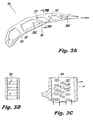
Fig. 2A is a cross-sectional end view of an exemplary embodiment of a turbomachine component in accordance with this disclosure, shown with pedestals disposed in a cooling channel thereof that are angled relative to an axis A of the turbomachine such the pedestals diverge from axis A; -
Fig. 2B is a partial cross-sectional view of the turbomachine component ofFig. 2A taken along line 2B-2B, showing the pedestals not angled in a radial direction of the turbomachine; -
Fig. 2C is a partial cross-sectional view of the turbomachine component ofFig. 2A taken along line 2C-2C, showing the pedestals angled only circumferentially tangential relative to the turbomachine axis A; -
Fig. 3A is a cross-sectional elevation view of an exemplary embodiment of a turbomachine component in accordance with this disclosure, shown with pedestals disposed in a cooling channel thereof that are angled relative to axis A of the turbomachine opposite to that of the exemplary embodiment ofFig. 2A such the pedestals converge toward axis A; -
Fig. 3B is a partial cross-sectional view of the turbomachine component ofFig. 3A taken alongline 3B-3B, showing the pedestals not angled in a radial direction of the turbomachine; -
Fig. 3C is a partial cross-sectional view of the turbomachine component ofFig. 3A taken alongline 3C-3C, showing the pedestals angled only circumferentially tangential relative to the turbomachine axis A; -
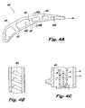
Fig. 4A is a cross-sectional elevation view of an exemplary embodiment of a turbomachine component in accordance with this disclosure, shown with pedestals disposed in a cooling channel thereof that are not angled in the axial direction of axis A, i.e., the pedestals do not converge or diverge relative to axis A of turbomachine; -
Fig. 4B is a partial cross-sectional view of the turbomachine component ofFig. 4A taken alongline 4B-4B, showing the pedestals angled in the radial direction of the turbomachine; -
Fig. 4C is a partial cross-sectional view of the turbomachine component ofFig. 4A taken alongline 4C-4C, showing the pedestals angled in only the radial direction; -
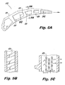
Fig. 5A is a cross-sectional elevation view of an exemplary embodiment of a turbomachine component in accordance with this disclosure, shown with pedestals disposed in a cooling channel thereof that are not angled in the axial direction of axis A, i.e., the pedestals do not converge or diverge relative to axis A of turbomachine; -
Fig. 5B is a partial cross-sectional view of the turbomachine component ofFig. 5A taken alongline 5B-5B, showing the pedestals angled in the radial direction of the turbomachine; -
Fig. 5C is a partial cross-sectional view of the turbomachine component ofFig. 5A taken alongline 5C-5C, showing the pedestals angled in only the radial direction opposite to that of the embodiment ofFig. 4A ; -
Fig. 6A is a cross-sectional elevation view of an exemplary embodiment of a turbomachine component in accordance with this disclosure, shown with pedestals disposed in a cooling channel thereof that are angled relative to both an axial and radial direction of the turbomachine, i.e., circumferentially tangential and radially angled; -
Fig. 6B is a partial cross-sectional view of the turbomachine component ofFig. 6A taken alongline 6B-6B, showing the pedestals angled in the radial direction of the turbomachine; -
Fig. 6C is a partial cross-sectional view of the turbomachine component ofFig. 6A taken alongline 6C-6C, showing the pedestals angled in both the axial and radial directions; -
Fig. 7A is a cross-sectional elevation view of an exemplary embodiment of a turbomachine component in accordance with this disclosure, shown with pedestals disposed in a cooling channel thereof that are angled relative to both an axial and radial direction of the turbomachine, i.e., circumferentially tangential and radially angled; -
Fig. 7B is a partial cross-sectional view of the turbomachine component ofFig. 7A taken alongline 7B-7B, showing the pedestals angled in the radial direction of the turbomachine; and -
Fig. 7C is a partial cross-sectional view of the turbomachine component ofFig. 7A taken alongline 7C-7C, showing the pedestals angled in both the axial and radial directions. - Reference will now be made to the drawings wherein like reference numerals identify similar structural features or aspects of the subject disclosure. For purposes of explanation and illustration, and not limitation, an illustrative view of an exemplary embodiment of a turbomachine blade in accordance with the disclosure is shown in
Fig. 2 and is designated generally byreference character 200. Other exemplary embodiments and/or aspects of this disclosure are shown inFigs. 1 and2B-7C . The systems and methods described herein can be used to enhance thermal transfer within components that have cooling channels. -
Fig. 1 schematically illustrates agas turbine engine 20. Thegas turbine engine 20 is disclosed herein as a two-spool turbofan that generally incorporates afan section 22, acompressor section 24, acombustor section 26 and aturbine section 28. Alternative engines might include an augmentor section (not shown) among other systems or features. Thefan section 22 drives air along a bypass flow path B in a bypass duct defined within anacelle 15, while thecompressor section 24 drives air along a core flow path C for compression and communication into thecombustor section 26 then expansion through theturbine section 28. Although depicted as a two-spool turbofan gas turbine engine in the disclosed non-limiting embodiment, it should be understood that the concepts described herein are not limited to use with two-spool turbofans as the teachings may be applied to other types of turbine engines including three-spool architectures. - The
exemplary engine 20 generally includes alow speed spool 30 and ahigh speed spool 32 mounted for rotation about an engine central longitudinal axis A relative to an enginestatic structure 36 viaseveral bearing systems 38. It should be understood that various bearingsystems 38 at various locations may alternatively or additionally be provided and the location of bearingsystems 38 may be varied as appropriate to the application. - The
low speed spool 30 generally includes an inner shaft 40 that interconnects afan 42, a first (or low) pressure compressor 44 and a first (or low)pressure turbine 46. The inner shaft 40 is connected to thefan 42 through a speed change mechanism, which in exemplarygas turbine engine 20 is illustrated as agear system 48 to drive thefan 42 at a lower speed than thelow speed spool 30. Thehigh speed spool 32 includes anouter shaft 50 that interconnects a second (or high)pressure compressor 52 and a second (or high)pressure turbine 54. Acombustor 56 is arranged inexemplary gas turbine 20 between thehigh pressure compressor 52 and thehigh pressure turbine 54. Amid-turbine frame 57 of the enginestatic structure 36 is arranged generally between thehigh pressure turbine 54 and thelow pressure turbine 46. Themid-turbine frame 57 furthersupports bearing systems 38 in theturbine section 28. The inner shaft 40 and theouter shaft 50 are concentric and rotate via bearingsystems 38 about the engine central longitudinal axis A which is collinear with their longitudinal axes. - The core airflow is compressed by the low pressure compressor 44 then the
high pressure compressor 52, mixed and burned with fuel in thecombustor 56, then expanded over thehigh pressure turbine 54 andlow pressure turbine 46. Themid-turbine frame 57 includes airfoils 59 which are in the core airflow path C. Theturbines low speed spool 30 andhigh speed spool 32 in response to the expansion. It will be appreciated that each of the positions of thefan section 22,compressor section 24,combustor section 26,turbine section 28, andfan gear system 48 may be varied. For example,gear system 48 may be located aft ofcombustor section 26 or even aft ofturbine section 28, andfan section 22 may be positioned forward or aft of the location ofgear system 48. - The
engine 20 in one example is a high-bypass geared aircraft engine. In a further example, theengine 20 bypass ratio is greater than about six (6), with an example embodiment being greater than about ten (10), the geared architecture is an epicyclic gear train, such as a planetary gear system or other gear system, with a gear reduction ratio of greater than about 2.3 and thelow pressure turbine 46 has a pressure ratio that is greater than about five. In one disclosed exemplary embodiment, theengine 20 bypass ratio is greater than about ten (10:1), the fan diameter is significantly larger than that of the low pressure compressor 44, and thelow pressure turbine 46 has a pressure ratio that is greater than about five (5:1).Low pressure turbine 46 pressure ratio is pressure measured prior to inlet oflow pressure turbine 46 as related to the pressure at the outlet of thelow pressure turbine 46 prior to an exhaust nozzle. The geared architecture may be an epicycle gear train, such as a planetary gear system or other gear system, with a gear reduction ratio of greater than about 2.3:1. It should be understood, however, that the above parameters are only exemplary of one embodiment of a geared architecture engine and that the present disclosure is applicable to other gas turbine engines including direct drive turbofans. - A significant amount of thrust is provided by the bypass flow B due to the high bypass ratio. The
fan section 22 of theengine 20 is designed for a particular flight condition -- typically cruise at about 0.8 Mach and about 35,000 feet. The flight condition of 0.8 Mach and 35,000 ft (10,668 meters), with the engine at its best fuel consumption - also known as "bucket cruise Thrust Specific Fuel Consumption ('TSFC')" - is the industry standard parameter of lbm of fuel being burned divided by lbf of thrust the engine produces at that minimum point. "Low fan pressure ratio" is the pressure ratio across the fan blade alone, without a Fan Exit Guide Vane 79("FEGV") system. The low fan pressure ratio as disclosed herein according to one non-limiting embodiment is less than about 1.45. "Low corrected fan tip speed" is the actual fan tip speed in ft/sec divided by an industry standard temperature correction of [(Tram °R) / (518.7 °R)]^0.5. The "Low corrected fan tip speed" as disclosed herein according to one non-limiting embodiment is less than about 1150 ft / second (350.5 meters/second). - Referring to
Figs. 2A-2C , aturbomachine component 200 includes abody 202 defining acooling inlet 202a (Fig. 2C ) and acooling outlet 202b in fluid communication with each other through acooling channel 201 that defines a longitudinal axis, and one ormore pedestals 203 disposed within the coolingchannel 201. One or more of thepedestals 203 are angled within the coolingchannel 201 relative to the longitudinal axis. Another way to describe the angle of thepedestals 203 is that thepedestals 203 or a portion thereof can meet one or both of theinterior walls 201a, 201b that define thecooling channel 201 at a non-right angle. Thepedestals 203 can be angled to any suitable angle degree (e.g., about 10 degrees to about 90 degrees). - As shown in
Fig. 2C , thepedestals 203 can include a circular cross-sectional shape, however, it is contemplated that any suitable cross-sectional shape (constant or variable) or combinations thereof can be used. For example, one or more of thepedestals 203 can include an elliptical, square, or other suitable cross-sectional shape and may have any suitable thickness or changing thickness along the length of thepedestals 203. - The
turbomachine component 200 can be a blade or vane including an airfoil or any other suitable component with cooling channels (e.g., a blade outer air seal, a combustor panel). As shown, thepedestals 203 can be angled within the coolingchannel 201 relative to an axial direction (axis A) of a turbomachine (e.g., circumferentially tangential). Referring toFig. 2B and 2C , the pedestals can be non-angled or perpendicular relative to a radial direction (e.g., longitudinal direction of the cooling channel 201) of the turbomachine, but can be angled with a forward-slash sweep such that thepedestals 203 diverge relative to axis A. - As shown, the
turbomachine component 200 can include a plurality ofpedestals 203 where at least twopedestals 203 in the plurality ofpedestals 203 have a different angle degree and/or angle direction relative to each other. For example, as shown inFig. 2A , thepedestals 203 can have differing angles (e.g., angles 0, γ, α, and β) relative to the axis A. This can be due to anon-linear cooling channel 201 formed by the shape of the airfoil cross-section. Also as shown inFig. 2C , the plurality ofpedestals 203 can be disposed in any suitable predetermined pattern. For example, the predetermined pattern can include one or more rows or columns ofpedestals 203. - Referring to
Figs. 3A-3C , aturbomachine component 300 similar tocomponent 200 can include abody 302 andpedestals 303 that are angled within the coolingchannel 301 in a direction opposite to that of the embodiment ofFigs. 2A-2C , e.g., such that the pedestals are circumferentially tangentially angled to converge relative to the axis A. - In certain exemplary embodiments, as shown in
Fig. 4A-4C , aturbomachine component 400 can include abody 402 havingpedestals 403 disposed in acooling channel 401 that are angled relative to a radial direction of a turbomachine. As shown inFig. 4B , thepedestals 403 can be angled radially outward to radially inward. Referring toFigs. 5A-5C , aturbomachine component 500 similar tocomponent 400 can include abody 502 andpedestals 503 that are angled within the coolingchannel 501 in a radial direction opposite to that of the exemplary embodiment ofFigs. 4A-4C . - In certain exemplary embodiments, as shown in
Fig. 6A-6C , aturbomachine component 600 can include abody 602 havingpedestals 603 disposed in acooling channel 601 that are angled within the coolingchannel 601 relative to both an axial direction and a radial direction of a turbomachine. Referring toFigs. 7A-7C , aturbomachine component 700 similar tocomponent 600 can include abody 702 andpedestals 703 that are angled within the coolingchannel 701 in an axial and/or radial direction that is different to that of the exemplary embodiment ofFigs. 6A-6C . - In at least one aspect of this disclosure, a method includes forming a turbomachine component (e.g., component 200) as described above. Forming can include additively manufacturing the
turbomachine component 200. Forming can include shaping or otherwise forming thebody 202 into a turbomachine blade including an airfoil. Other methods of manufacturing include conventional casting methods including electric discharge machining (EDM) or Laser of the core structure used to produce the negative of the airfoil. - The angled pedestals of any of the exemplary embodiments described herein allow for flow directional control and/or modification to enhance thermal control of components with cooling channels. For example, the
angled pedestals 203 as shown inFigs. 2A-2C can guide a forward-to-aft flow upward toward an upper surface defining the cooling channel. As will be appreciated by one having ordinary skill in the art, the direction and degree of angle of the pedestals can be selected to modify impingement on a desired portion of the cooling channel to regulate temperatures at certain portions of the turbomachine component as desired. - The methods and systems of the present disclosure, as described above and shown in the drawings, provide for enhanced components with cooling channels having superior properties including enhanced thermal efficiency. While the apparatus and methods of the subject disclosure have been shown and described with reference to exemplary embodiments, those skilled in the art will readily appreciate that changes and/or modifications may be made thereto without departing from the scope of the subject disclosure.
- The following clauses set out features of the invention which may or may not be presently be claimed but which may form the basis for future amendments and/or a divisional application.
- 1. A turbomachine component, comprising:
- a body defining a cooling inlet and a cooling outlet in fluid communication with each other through a cooling channel that defines a longitudinal axis; and
- at least one pedestal disposed within the cooling channel, wherein the pedestal is angled within the cooling channel relative to the longitudinal axis.
- 2. The turbomachine of clause 1, wherein the at least one pedestal is angled between about 10 degrees to about 90 degrees relative to the longitudinal axis.
- 3. The turbomachine component of clause 1, wherein the turbomachine component is a vane, a blade, a blade outer air seal, or a combustor panel.
- 4. The turbomachine component of clause 1, wherein the pedestal is angled tangentially circumferential within the cooling channel relative to an axial direction that is parallel to the longitudinal axis.
- 5. The turbomachine component of clause 1, wherein the pedestal is angled radially within the cooling channel relative to an axial direction that is perpendicular to the longitudinal axis.
- 6. The turbomachine component of clause 5, wherein the pedestal is also angled tangentially circumferential within the cooling channel relative to an axial direction that is parallel to the longitudinal axis.
- 7. The turbomachine component of clause 2, wherein the pedestal includes a circular, elliptical, or square cross-sectional shape.
- 8. The turbomachine component of clause 2, further comprising a plurality of pedestals that are angled relative to one another.
- 9. The turbomachine component of
clause 8, wherein at least two pedestals in the plurality of pedestals have a different angle degree and/or angle direction relative to each other. - 10. The turbomachine component of
clause 8, wherein the plurality of pedestals are disposed in a predetermined pattern relative to each other. - 11. The turbomachine component of
clause 10, wherein the predetermined pattern includes one or more rows or columns. - 12. A method, comprising:
- forming a turbomachine component having a body defining a cooling inlet and a cooling outlet in fluid communication with each other through a cooling channel that defines a longitudinal axis, wherein at least one pedestal is disposed within the cooling channel, wherein the pedestal is angled within the cooling channel relative to the longitudinal axis.
- 13. The method of clause 12, wherein forming includes at least one of additively manufacturing the turbomachine component, using electric discharge machining (EDM) to manufacture the turbomachine component, or using a laser to manufacture the turbomachine component.
- 14. The method of clause 13, wherein forming includes shaping the body into a turbomachine vane, blade, blade outer air seal, or combustor panel.
- 15. A turbomachine, comprising:
- a turbomachine component, having:
- a body defining a cooling inlet and a cooling outlet in fluid communication with each other through a cooling channel that defines a longitudinal axis; and
- at least one pedestal disposed within the cooling channel, wherein the pedestal is angled within the cooling channel relative to the longitudinal axis.
- a turbomachine component, having:
- 16. The turbomachine of
clause 15, wherein the at least one pedestal is angled between about 10 degrees to about 90 degrees relative to the longitudinal axis. - 17. The turbomachine of
clause 15, wherein the turbomachine component is a vane, a blade, a blade outer air seal, or a combustor panel. - 18. The turbomachine of
clause 15, wherein the pedestal is angled tangentially circumferential within the cooling channel relative to an axial direction that is parallel to the longitudinal axis. - 19. The turbomachine of
clause 15, wherein the pedestal is angled radially within the cooling channel relative to an axial direction that is perpendicular to the longitudinal axis. - 20. The turbomachine of clause 19, wherein the pedestal is also angled tangentially circumferential within the cooling channel relative to an axial direction that is parallel to the longitudinal axis.
Claims (15)
- A turbomachine component (200; 300; 400; 500; 600; 700), comprising:a body defining a cooling inlet (202a) and a cooling outlet (202b) in fluid communication with each other through a cooling channel (201; 301; 401; 501; 601; 701) that defines a longitudinal axis (A); andat least one pedestal (203; 303; 403; 503; 603; 703) disposed within the cooling channel, wherein the pedestal is angled within the cooling channel relative to the longitudinal axis.
- The turbomachine component (200; 300; 400; 500; 600; 700) of claim 1, wherein the at least one pedestal (203; 303; 403; 503; 603; 703) is angled between about 10 degrees to about 90 degrees relative to the longitudinal axis (A).
- The turbomachine component (200; 300; 400; 500; 600; 700) of claim 1 or 2, wherein the turbomachine component is a vane, a blade, a blade outer air seal, or a combustor panel.
- The turbomachine component (200; 300) of claim 1, 2 or 3, wherein the pedestal (203; 303) is angled tangentially circumferential within the cooling channel (201; 301) relative to an axial direction that is parallel to the longitudinal axis (A).
- The turbomachine component (400; 500) of claim 1, 2 or 3, wherein the pedestal (403; 503) is angled radially within the cooling channel (401; 501) relative to an axial direction that is perpendicular to the longitudinal axis (A).
- The turbomachine component (400; 500) of claim 5, wherein the pedestal (403; 503) is also angled tangentially circumferential within the cooling channel (401; 501) relative to an axial direction that is parallel to the longitudinal axis.
- The turbomachine component (200; 300; 400; 500; 600; 700) of claim 1 or 2, wherein the pedestal (203; 303; 403; 503; 603; 703) includes a circular, elliptical, or square cross-sectional shape.
- The turbomachine component (200; 300; 400; 500; 600; 700) of claim 1 or 2, further comprising a plurality of pedestals (203; 303; 403; 503; 603; 703) that are angled relative to one another.
- The turbomachine component (200; 300; 400; 500; 600; 700) of claim 8, wherein at least two pedestals (203; 303; 403; 503; 603; 703) in the plurality of pedestals have a different angle degree and/or angle direction relative to each other.
- The turbomachine component (200; 300; 400; 500; 600; 700) of claim 8 or 9, wherein the plurality of pedestals (203; 303; 403; 503; 603; 703) are disposed in a predetermined pattern relative to each other.
- The turbomachine component (200; 300; 400; 500; 600; 700) of claim 10, wherein the predetermined pattern includes one or more rows or columns.
- A method, comprising:forming a turbomachine component (200; 300; 400; 500; 600; 700) having a body defining a cooling inlet (202a) and a cooling outlet (202b) in fluid communication with each other through a cooling channel (201; 301; 401; 501; 601; 701) that defines a longitudinal axis (A), wherein at least one pedestal (203; 303; 403; 503; 603; 703) is disposed within the cooling channel, wherein the pedestal is angled within the cooling channel relative to the longitudinal axis.
- The method of claim 12, wherein forming includes at least one of additively manufacturing the turbomachine component (200; 300; 400; 500; 600; 700), using electric discharge machining (EDM) to manufacture the turbomachine component, or using a laser to manufacture the turbomachine component.
- The method of claim 12 or 13, wherein forming includes shaping the body into a turbomachine vane, blade, blade outer air seal, or combustor panel.
- A turbomachine, comprising:a turbomachine component (200; 300; 400; 500; 600; 700) as described in any of claims 1 to 11.
Applications Claiming Priority (1)
| Application Number | Priority Date | Filing Date | Title |
|---|---|---|---|
| US14/619,582 US20160230566A1 (en) | 2015-02-11 | 2015-02-11 | Angled pedestals for cooling channels |
Publications (1)
| Publication Number | Publication Date |
|---|---|
| EP3056670A1 true EP3056670A1 (en) | 2016-08-17 |
Family
ID=54849534
Family Applications (1)
| Application Number | Title | Priority Date | Filing Date |
|---|---|---|---|
| EP15199495.1A Withdrawn EP3056670A1 (en) | 2015-02-11 | 2015-12-11 | Turbomachine component having cooling channels with angled pedestals |
Country Status (2)
| Country | Link |
|---|---|
| US (1) | US20160230566A1 (en) |
| EP (1) | EP3056670A1 (en) |
Cited By (1)
| Publication number | Priority date | Publication date | Assignee | Title |
|---|---|---|---|---|
| DE102018205721A1 (en) | 2018-04-16 | 2019-10-17 | MTU Aero Engines AG | Blade for a turbomachine and use and manufacturing method thereof |
Families Citing this family (4)
| Publication number | Priority date | Publication date | Assignee | Title |
|---|---|---|---|---|
| US20160298465A1 (en) * | 2013-12-12 | 2016-10-13 | United Technologies Corporation | Gas turbine engine component cooling passage with asymmetrical pedestals |
| US20180149028A1 (en) * | 2016-11-30 | 2018-05-31 | General Electric Company | Impingement insert for a gas turbine engine |
| EP3492702A1 (en) * | 2017-11-29 | 2019-06-05 | Siemens Aktiengesellschaft | Internally-cooled turbomachine component |
| FR3111414B1 (en) * | 2020-06-15 | 2022-09-02 | Safran Helicopter Engines | PRODUCTION BY ADDITIVE MANUFACTURING OF COMPLEX PARTS |
Citations (6)
| Publication number | Priority date | Publication date | Assignee | Title |
|---|---|---|---|---|
| US3171631A (en) * | 1962-12-05 | 1965-03-02 | Gen Motors Corp | Turbine blade |
| GB2270718A (en) * | 1992-09-22 | 1994-03-23 | Rolls Royce Plc | Single crystal turbine blades having pedestals. |
| US20120076660A1 (en) * | 2010-09-28 | 2012-03-29 | Spangler Brandon W | Conduction pedestals for a gas turbine engine airfoil |
| US20130064639A1 (en) * | 2011-09-12 | 2013-03-14 | Honeywell International Inc. | Gas turbine engines with improved trailing edge cooling arrangements |
| WO2013138009A1 (en) * | 2012-03-13 | 2013-09-19 | United Technologies Corporation | Improved cooling pedestal array |
| US20140093387A1 (en) * | 2012-09-28 | 2014-04-03 | Solar Turbines Incorporated | Method of manufacturing a cooled turbine blade with dense cooling fin array |
Family Cites Families (4)
| Publication number | Priority date | Publication date | Assignee | Title |
|---|---|---|---|---|
| US4236870A (en) * | 1977-12-27 | 1980-12-02 | United Technologies Corporation | Turbine blade |
| US5700132A (en) * | 1991-12-17 | 1997-12-23 | General Electric Company | Turbine blade having opposing wall turbulators |
| US7094031B2 (en) * | 2004-09-09 | 2006-08-22 | General Electric Company | Offset Coriolis turbulator blade |
| EP2180141B1 (en) * | 2008-10-27 | 2012-09-12 | Alstom Technology Ltd | Cooled blade for a gas turbine and gas turbine having such a blade |
-
2015
- 2015-02-11 US US14/619,582 patent/US20160230566A1/en not_active Abandoned
- 2015-12-11 EP EP15199495.1A patent/EP3056670A1/en not_active Withdrawn
Patent Citations (6)
| Publication number | Priority date | Publication date | Assignee | Title |
|---|---|---|---|---|
| US3171631A (en) * | 1962-12-05 | 1965-03-02 | Gen Motors Corp | Turbine blade |
| GB2270718A (en) * | 1992-09-22 | 1994-03-23 | Rolls Royce Plc | Single crystal turbine blades having pedestals. |
| US20120076660A1 (en) * | 2010-09-28 | 2012-03-29 | Spangler Brandon W | Conduction pedestals for a gas turbine engine airfoil |
| US20130064639A1 (en) * | 2011-09-12 | 2013-03-14 | Honeywell International Inc. | Gas turbine engines with improved trailing edge cooling arrangements |
| WO2013138009A1 (en) * | 2012-03-13 | 2013-09-19 | United Technologies Corporation | Improved cooling pedestal array |
| US20140093387A1 (en) * | 2012-09-28 | 2014-04-03 | Solar Turbines Incorporated | Method of manufacturing a cooled turbine blade with dense cooling fin array |
Cited By (1)
| Publication number | Priority date | Publication date | Assignee | Title |
|---|---|---|---|---|
| DE102018205721A1 (en) | 2018-04-16 | 2019-10-17 | MTU Aero Engines AG | Blade for a turbomachine and use and manufacturing method thereof |
Also Published As
| Publication number | Publication date |
|---|---|
| US20160230566A1 (en) | 2016-08-11 |
Similar Documents
| Publication | Publication Date | Title |
|---|---|---|
| EP3348803B1 (en) | Engine mid-turbine frame transfer tube for low pressure turbine case cooling | |
| EP3091184B1 (en) | Turbine airfoil leading edge cooling | |
| EP3034791B1 (en) | Heat transfer pedestals with flow guide features | |
| EP3628819B1 (en) | Ribbed pin fins | |
| EP3056670A1 (en) | Turbomachine component having cooling channels with angled pedestals | |
| EP3514331B1 (en) | Cooled airfoil and corresponding gas turbine engine | |
| WO2014159800A1 (en) | Obtuse angle chevron trip strip | |
| EP3012408B1 (en) | Gas turbine engine component with combustor wall having cooling hole | |
| WO2015163949A2 (en) | Fan cooling hole array | |
| EP3045666B1 (en) | Airfoil platform with cooling feed orifices | |
| EP3351731A1 (en) | Trailing edge configuration with cast slots and drilled filmholes | |
| EP3502420B1 (en) | Component for a gas turbine engine and corresponding gas turbine engine | |
| US20140208771A1 (en) | Gas turbine engine component cooling arrangement | |
| EP3453831A2 (en) | Airfoil having end wall contoured pedestals | |
| EP3663517B1 (en) | Component for a gas turbine engine and corresponding gas turbine engine | |
| EP2961964B1 (en) | Gas turbine engine component and corresponding method of manufacturing an aperture | |
| EP3564486B1 (en) | Airfoil having improved cooling scheme | |
| EP3392567A1 (en) | Combustor liner panel end rail | |
| EP3105436A2 (en) | Gas turbine engine component with separation rib for cooling passages |
Legal Events
| Date | Code | Title | Description |
|---|---|---|---|
| PUAI | Public reference made under article 153(3) epc to a published international application that has entered the european phase |
Free format text: ORIGINAL CODE: 0009012 |
|
| AK | Designated contracting states |
Kind code of ref document: A1 Designated state(s): AL AT BE BG CH CY CZ DE DK EE ES FI FR GB GR HR HU IE IS IT LI LT LU LV MC MK MT NL NO PL PT RO RS SE SI SK SM TR |
|
| AX | Request for extension of the european patent |
Extension state: BA ME |
|
| RAP1 | Party data changed (applicant data changed or rights of an application transferred) |
Owner name: UNITED TECHNOLOGIES CORPORATION |
|
| STAA | Information on the status of an ep patent application or granted ep patent |
Free format text: STATUS: REQUEST FOR EXAMINATION WAS MADE |
|
| 17P | Request for examination filed |
Effective date: 20170210 |
|
| RBV | Designated contracting states (corrected) |
Designated state(s): AL AT BE BG CH CY CZ DE DK EE ES FI FR GB GR HR HU IE IS IT LI LT LU LV MC MK MT NL NO PL PT RO RS SE SI SK SM TR |
|
| STAA | Information on the status of an ep patent application or granted ep patent |
Free format text: STATUS: EXAMINATION IS IN PROGRESS |
|
| 17Q | First examination report despatched |
Effective date: 20190806 |
|
| STAA | Information on the status of an ep patent application or granted ep patent |
Free format text: STATUS: THE APPLICATION HAS BEEN WITHDRAWN |
|
| 18W | Application withdrawn |
Effective date: 20191029 |