EP3056286A1 - Nebulizing driving apparatus and nebulizing system - Google Patents
Nebulizing driving apparatus and nebulizing system Download PDFInfo
- Publication number
- EP3056286A1 EP3056286A1 EP15190806.8A EP15190806A EP3056286A1 EP 3056286 A1 EP3056286 A1 EP 3056286A1 EP 15190806 A EP15190806 A EP 15190806A EP 3056286 A1 EP3056286 A1 EP 3056286A1
- Authority
- EP
- European Patent Office
- Prior art keywords
- driving
- circuit
- frequency
- piezoelectric material
- electrical data
- Prior art date
- Legal status (The legal status is an assumption and is not a legal conclusion. Google has not performed a legal analysis and makes no representation as to the accuracy of the status listed.)
- Granted
Links
Images





Classifications
-
- H—ELECTRICITY
- H10—SEMICONDUCTOR DEVICES; ELECTRIC SOLID-STATE DEVICES NOT OTHERWISE PROVIDED FOR
- H10N—ELECTRIC SOLID-STATE DEVICES NOT OTHERWISE PROVIDED FOR
- H10N30/00—Piezoelectric or electrostrictive devices
- H10N30/80—Constructional details
- H10N30/802—Circuitry or processes for operating piezoelectric or electrostrictive devices not otherwise provided for, e.g. drive circuits
-
- B—PERFORMING OPERATIONS; TRANSPORTING
- B05—SPRAYING OR ATOMISING IN GENERAL; APPLYING FLUENT MATERIALS TO SURFACES, IN GENERAL
- B05B—SPRAYING APPARATUS; ATOMISING APPARATUS; NOZZLES
- B05B12/00—Arrangements for controlling delivery; Arrangements for controlling the spray area
- B05B12/08—Arrangements for controlling delivery; Arrangements for controlling the spray area responsive to condition of liquid or other fluent material to be discharged, of ambient medium or of target ; responsive to condition of spray devices or of supply means, e.g. pipes, pumps or their drive means
- B05B12/081—Arrangements for controlling delivery; Arrangements for controlling the spray area responsive to condition of liquid or other fluent material to be discharged, of ambient medium or of target ; responsive to condition of spray devices or of supply means, e.g. pipes, pumps or their drive means responsive to the weight of a reservoir or container for liquid or other fluent material; responsive to level or volume of liquid or other fluent material in a reservoir or container
-
- B—PERFORMING OPERATIONS; TRANSPORTING
- B05—SPRAYING OR ATOMISING IN GENERAL; APPLYING FLUENT MATERIALS TO SURFACES, IN GENERAL
- B05B—SPRAYING APPARATUS; ATOMISING APPARATUS; NOZZLES
- B05B17/00—Apparatus for spraying or atomising liquids or other fluent materials, not covered by the preceding groups
- B05B17/04—Apparatus for spraying or atomising liquids or other fluent materials, not covered by the preceding groups operating with special methods
- B05B17/06—Apparatus for spraying or atomising liquids or other fluent materials, not covered by the preceding groups operating with special methods using ultrasonic or other kinds of vibrations
- B05B17/0607—Apparatus for spraying or atomising liquids or other fluent materials, not covered by the preceding groups operating with special methods using ultrasonic or other kinds of vibrations generated by electrical means, e.g. piezoelectric transducers
-
- B—PERFORMING OPERATIONS; TRANSPORTING
- B05—SPRAYING OR ATOMISING IN GENERAL; APPLYING FLUENT MATERIALS TO SURFACES, IN GENERAL
- B05B—SPRAYING APPARATUS; ATOMISING APPARATUS; NOZZLES
- B05B17/00—Apparatus for spraying or atomising liquids or other fluent materials, not covered by the preceding groups
- B05B17/04—Apparatus for spraying or atomising liquids or other fluent materials, not covered by the preceding groups operating with special methods
- B05B17/06—Apparatus for spraying or atomising liquids or other fluent materials, not covered by the preceding groups operating with special methods using ultrasonic or other kinds of vibrations
- B05B17/0607—Apparatus for spraying or atomising liquids or other fluent materials, not covered by the preceding groups operating with special methods using ultrasonic or other kinds of vibrations generated by electrical means, e.g. piezoelectric transducers
- B05B17/0653—Details
- B05B17/0669—Excitation frequencies
-
- H—ELECTRICITY
- H10—SEMICONDUCTOR DEVICES; ELECTRIC SOLID-STATE DEVICES NOT OTHERWISE PROVIDED FOR
- H10N—ELECTRIC SOLID-STATE DEVICES NOT OTHERWISE PROVIDED FOR
- H10N30/00—Piezoelectric or electrostrictive devices
- H10N30/20—Piezoelectric or electrostrictive devices with electrical input and mechanical output, e.g. functioning as actuators or vibrators
Definitions
- the present invention relates to a driving apparatus and a system, and especially relates to a nebulizing driving apparatus and a nebulizing system.
- a nebulizer is a very common electronic apparatus.
- a related art nebulizer comprises a liquid chamber, a piezoelectric material and a driving circuit.
- the liquid chamber is connected to the piezoelectric material.
- the driving circuit is electrically connected to the piezoelectric material.
- the liquid chamber is used for containing liquid, for example medicinal liquid.
- the driving circuit is used for driving the piezoelectric material. Liquid in the liquid chamber is nebulized when the driving circuit drives the piezoelectric material.
- the working frequency of the nebulizer (namely, the frequency which the driving circuit drives the piezoelectric material) is usually between 100 KHz to 150 KHz.
- an object of the present invention is to provide a nebulizing driving apparatus.
- another object of the present invention is to provide a nebulizing system.
- the nebulizing driving apparatus is used to drive a piezoelectric material of a nebulizing module.
- the nebulizing driving apparatus comprises a driving circuit, a control circuit and a feedback circuit.
- the driving circuit is electrically connected to the piezoelectric material.
- the control circuit is electrically connected to the driving circuit.
- the feedback circuit is electrically connected to the driving circuit, the control circuit and the piezoelectric material.
- the feedback circuit detects an electrical data fed back from the piezoelectric material and sends the electrical data to the control circuit when the control circuit is configured to control the driving circuit to drive the piezoelectric material with a driving frequency.
- the control circuit is configured to control the driving circuit to drive the piezoelectric material with a working frequency.
- the nebulizing module further comprises a liquid chamber connected to the piezoelectric material. A liquid in the liquid chamber is nebulized when the driving circuit drives the piezoelectric material.
- the feedback circuit detects a plurality of the electrical data fed back from the piezoelectric material in accordance with a plurality of different driving frequencies and sends the electrical data to the control circuit when the control circuit is configured to control the driving circuit to drive the piezoelectric material with the different driving frequencies.
- the control circuit is configured to determine the working frequency.
- control circuit selects the driving frequency in accordance with a maximum of the electrical data as the working frequency.
- control circuit selects a current driving frequency as the working frequency when the electrical data in accordance with the current driving frequency is greater than the electrical data in accordance with a previous driving frequency and is greater than the electrical data in accordance with a next driving frequency.
- the next driving frequency is greater than the current driving frequency.
- the current driving frequency is greater than the previous driving frequency.
- the electrical data in accordance with the working frequency is a maximum of a plurality of current values when the electrical data are the current values.
- the electrical data in accordance with the working frequency is a maximum of a plurality of voltage values when the electrical data are the voltage values.
- control circuit calculates a plurality of current values multiplied by a plurality of voltage values in accordance with the current values respectively to obtain a plurality of power values when the electrical data are the current values and the voltage values in accordance with the current values.
- the control circuit selects the driving frequency in accordance with a maximum of the power values as the working frequency.
- the control circuit controls the driving circuit to drive the piezoelectric material with the working frequency
- the feedback circuit detects that the electrical data fed back from the piezoelectric material is less than or greater than the maximum of the electrical data an offset over a predetermined time
- the control circuit controls the driving circuit to stop driving the piezoelectric material. For example, if the maximum of the electrical data is 1 and the offset is 0.1 and the predetermined time is 2 seconds, the piezoelectric material won't be driven if the electrical data fed back from the piezoelectric material is less than 0.9 or greater than 1.1 over 2 seconds.
- the feedback circuit comprises a voltage detection sub-circuit and a current detection sub-circuit.
- the voltage detection sub-circuit is electrically connected to the driving circuit, the control circuit and the piezoelectric material.
- the current detection sub-circuit is electrically connected to the control circuit and the piezoelectric material.
- the nebulizing system comprises a nebulizing driving apparatus and a nebulizing module electrically connected to the nebulizing driving apparatus.
- the nebulizing module comprises a piezoelectric material electrically connected to the nebulizing driving apparatus.
- the nebulizing driving apparatus comprises a driving circuit, a control circuit and a feedback circuit.
- the driving circuit is electrically connected to the piezoelectric material.
- the control circuit is electrically connected to the driving circuit.
- the feedback circuit is electrically connected to the driving circuit, the control circuit and the piezoelectric material.
- the feedback circuit detects an electrical data fed back from the piezoelectric material and sends the electrical data to the control circuit when the control circuit is configured to control the driving circuit to drive the piezoelectric material with a driving frequency. According to the electrical data, the control circuit is configured to control the driving circuit to drive the piezoelectric material with a working frequency.
- the nebulizing module further comprises a liquid chamber connected to the piezoelectric material. A liquid in the liquid chamber is nebulized when the driving circuit drives the piezoelectric material.
- the feedback circuit detects a plurality of the electrical data fed back from the piezoelectric material in accordance with a plurality of different driving frequencies and sends the electrical data to the control circuit when the control circuit is configured to control the driving circuit to drive the piezoelectric material with the different driving frequencies.
- the control circuit is configured to determine the working frequency.
- control circuit selects the driving frequency in accordance with a maximum of the electrical data as the working frequency.
- control circuit selects a current driving frequency as the working frequency when the electrical data in accordance with the current driving frequency is greater than the electrical data in accordance with a previous driving frequency and is greater than the electrical data in accordance with a next driving frequency.
- the next driving frequency is greater than the current driving frequency.
- the current driving frequency is greater than the previous driving frequency.
- Fig. 1 shows a block diagram of the nebulizing driving apparatus of the present invention.
- Fig. 2 shows an assembly drawing of the nebulizing driving apparatus of the present invention.
- a nebulizing driving apparatus 10 is used to drive a piezoelectric material 202 of a nebulizing module 20.
- the nebulizing module 20 comprises the piezoelectric material 202 and a liquid chamber 204.
- the nebulizing driving apparatus 10 comprises a driving circuit 102, a control circuit 104 and a feedback circuit 106.
- the feedback circuit 106 comprises a voltage detection sub-circuit 10602 and a current detection sub-circuit 10604.
- the nebulizing module 20 is electrically connected to the nebulizing driving apparatus 10.
- the piezoelectric material 202 is electrically connected to the nebulizing driving apparatus 10.
- the driving circuit 102 is electrically connected to the piezoelectric material 202.
- the control circuit 104 is electrically connected to the driving circuit 102.
- the feedback circuit 106 is electrically connected to the driving circuit 102, the control circuit 104 and the piezoelectric material 202.
- the liquid chamber 204 is connected to the piezoelectric material 202.
- the voltage detection sub-circuit 10602 is electrically connected to the driving circuit 102, the control circuit 104 and the piezoelectric material 202.
- the current detection sub-circuit 10604 is electrically connected to the control circuit 104 and the piezoelectric material 202.
- the main feature of the present invention is that the feedback circuit 106 detects an electrical data 206 fed back from the piezoelectric material 202 and sends the electrical data 206 to the control circuit 104 when the control circuit 104 is configured to control the driving circuit 102 to drive the piezoelectric material 202 with a driving frequency. According to the electrical data 206, the control circuit 104 is configured to control the driving circuit 102 to drive the piezoelectric material 202 with a working frequency. A liquid in the liquid chamber 204 is nebulized when the driving circuit 102 drives the piezoelectric material 202.
- the feedback circuit 106 detects a plurality of the electrical data 206 fed back from the piezoelectric material 202 in accordance with a plurality of different driving frequencies and sends the electrical data 206 to the control circuit 104 when the control circuit 104 is configured to control the driving circuit 102 to drive the piezoelectric material 202 with the different driving frequencies.
- the control circuit 104 is configured to determine the working frequency. For example, the control circuit 104 selects the driving frequency in accordance with a maximum of the electrical data 206 as the working frequency.
- Fig. 3 shows a waveform diagram of an embodiment of the electrical data versus the driving frequencies of the present invention.
- the electrical data 206 can be voltage values, current values or power values.
- the control circuit 104 is configured to control the driving circuit 102 to drive the piezoelectric material 202 with a first frequency to a ninth frequency respectively (namely, the first frequency, a second frequency, a third frequency, a fourth frequency, a fifth frequency, a sixth frequency, a seventh frequency, an eighth frequency and the ninth frequency), so that the feedback circuit 106 detects a plurality of the electrical data 206 fed back from the piezoelectric material 202 in accordance with the first frequency to the ninth frequency respectively.
- the feedback circuit 106 informs the control circuit 104 of the electrical data 206.
- the control circuit 104 selects the driving frequency in accordance with the maximum of the electrical data 206 as the working frequency. As shown in Fig. 3 , the control circuit 104 selects the fifth frequency as the working frequency. After the working frequency is selected, the control circuit 104 is configured to control the driving circuit 102 to drive the piezoelectric material 202 with the working frequency, so that the liquid in the liquid chamber 204 is nebulized.
- Fig. 11 shows a waveform diagram of another embodiment of the electrical data versus the driving frequencies of the present invention.
- the voltage multiplied by the current equals the power.
- the voltage and the current have an inverse relationship when the power is fixed.
- the control circuit 104 selects the driving frequency in accordance with a minimum of the electrical data 206 as the working frequency.
- the control circuit 104 selects the fifth frequency as the working frequency.
- the present invention is to find out an extreme value (namely, the maximum and the minimum mentioned above).
- the extreme value is at a slope turning point, such as the fifth frequency shown in Fig. 3 (the slope changes from positive to negative) or Fig. 11 (the slope changes from negative to positive).
- the control circuit 104 selects a current driving frequency (for example, the fifth frequency) as the working frequency when the electrical data 206 in accordance with the current driving frequency (namely, the fifth frequency) is greater than the electrical data 206 in accordance with a previous driving frequency (for example, the fourth frequency) and is greater than the electrical data 206 in accordance with a next driving frequency (for example, the sixth frequency).
- the next driving frequency (namely, the sixth frequency) is greater than the current driving frequency (namely, the fifth frequency).
- the current driving frequency (namely, the fifth frequency) is greater than the previous driving frequency (namely, the fourth frequency).
- the electrical data 206 in accordance with the working frequency is a maximum of a plurality of current values when the electrical data 206 are the current values.
- the electrical data 206 in accordance with the working frequency is a maximum of a plurality of voltage values when the electrical data 206 are the voltage values.
- the control circuit 104 calculates a plurality of current values multiplied by a plurality of voltage values in accordance with the current values respectively to obtain a plurality of power values when the electrical data 206 are the current values and the voltage values in accordance with the current values.
- the control circuit 104 selects the driving frequency in accordance with a maximum of the power values as the working frequency.
- control circuit 104 controls the driving circuit 102 to drive the piezoelectric material 202 with the working frequency
- the feedback circuit 106 detects that the electrical data 206 fed back from the piezoelectric material 202 is less than or greater than the maximum of the electrical data 206 an offset over a predetermined time
- the control circuit 104 controls the driving circuit 102 to stop driving the piezoelectric material 202.
- the piezoelectric material 202 won't be driven if the electrical data 206 fed back from the piezoelectric material 202 is less than 0.9 or greater than 1.1 over 2 seconds.
- the nebulizing driving apparatus 10 even shuts down. This is because after the driving circuit 102 drives the piezoelectric material 202 with the working frequency, the electrical data 206 fed back from the piezoelectric material 202 shall approach the maximum of the electrical data 206. Therefore, once the offset is too large and over the predetermined time, the liquid in the liquid chamber 204 is determined as being exhausted.
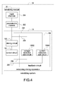
- FIG. 4 shows a block diagram of the nebulizing system of the present invention.
- Fig. 5 shows an assembly drawing of the nebulizing system of the present invention.
- a nebulizing system 30 comprises a nebulizing driving apparatus 10 and a nebulizing module 20.
- the nebulizing module 20 comprises a piezoelectric material 202 and a liquid chamber 204.
- the nebulizing driving apparatus 10 comprises a driving circuit 102, a control circuit 104 and a feedback circuit 106.
- the feedback circuit 106 comprises a voltage detection sub-circuit 10602 and a current detection sub-circuit 10604.
- the nebulizing module 20 is electrically connected to the nebulizing driving apparatus 10.
- the piezoelectric material 202 is electrically connected to the nebulizing driving apparatus 10.
- the driving circuit 102 is electrically connected to the piezoelectric material 202.
- the control circuit 104 is electrically connected to the driving circuit 102.
- the feedback circuit 106 is electrically connected to the driving circuit 102, the control circuit 104 and the piezoelectric material 202.
- the liquid chamber 204 is connected to the piezoelectric material 202.
- the voltage detection sub-circuit 10602 is electrically connected to the driving circuit 102, the control circuit 104 and the piezoelectric material 202.
- the current detection sub-circuit 10604 is electrically connected to the control circuit 104 and the piezoelectric material 202.
- the main feature of the present invention is that the feedback circuit 106 detects an electrical data 206 fed back from the piezoelectric material 202 and sends the electrical data 206 to the control circuit 104 when the control circuit 104 is configured to control the driving circuit 102 to drive the piezoelectric material 202 with a driving frequency. According to the electrical data 206, the control circuit 104 is configured to control the driving circuit 102 to drive the piezoelectric material 202 with a working frequency. A liquid in the liquid chamber 204 is nebulized when the driving circuit 102 drives the piezoelectric material 202.
- the feedback circuit 106 detects a plurality of the electrical data 206 fed back from the piezoelectric material 202 in accordance with a plurality of different driving frequencies and sends the electrical data 206 to the control circuit 104 when the control circuit 104 is configured to control the driving circuit 102 to drive the piezoelectric material 202 with the different driving frequencies.
- the control circuit 104 is configured to determine the working frequency. For example, the control circuit 104 selects the driving frequency in accordance with a maximum of the electrical data 206 as the working frequency.
- Fig. 3 shows a waveform diagram of an embodiment of the electrical data versus the driving frequencies of the present invention.
- the electrical data 206 can be voltage values, current values or power values.
- the control circuit 104 is configured to control the driving circuit 102 to drive the piezoelectric material 202 with a first frequency to a ninth frequency respectively (namely, the first frequency, a second frequency, a third frequency, a fourth frequency, a fifth frequency, a sixth frequency, a seventh frequency, an eighth frequency and the ninth frequency), so that the feedback circuit 106 detects a plurality of the electrical data 206 fed back from the piezoelectric material 202 in accordance with the first frequency to the ninth frequency respectively.
- the feedback circuit 106 informs the control circuit 104 of the electrical data 206.
- the control circuit 104 selects the driving frequency in accordance with the maximum of the electrical data 206 as the working frequency. As shown in Fig. 3 , the control circuit 104 selects the fifth frequency as the working frequency. After the working frequency is selected, the control circuit 104 is configured to control the driving circuit 102 to drive the piezoelectric material 202 with the working frequency, so that the liquid in the liquid chamber 204 is nebulized.
- Fig. 11 shows a waveform diagram of another embodiment of the electrical data versus the driving frequencies of the present invention.
- the voltage multiplied by the current equals the power.
- the voltage and the current have an inverse relationship when the power is fixed.
- the control circuit 104 selects the driving frequency in accordance with a minimum of the electrical data 206 as the working frequency.
- the control circuit 104 selects the fifth frequency as the working frequency.
- the present invention is to find out an extreme value (namely, the maximum and the minimum mentioned above).
- the extreme value is at a slope turning point, such as the fifth frequency shown in Fig. 3 (the slope changes from positive to negative) or Fig. 11 (the slope changes from negative to positive).
- the control circuit 104 selects a current driving frequency (for example, the fifth frequency) as the working frequency when the electrical data 206 in accordance with the current driving frequency (namely, the fifth frequency) is greater than the electrical data 206 in accordance with a previous driving frequency (for example, the fourth frequency) and is greater than the electrical data 206 in accordance with a next driving frequency (for example, the sixth frequency).
- the next driving frequency (namely, the sixth frequency) is greater than the current driving frequency (namely, the fifth frequency).
- the current driving frequency (namely, the fifth frequency) is greater than the previous driving frequency (namely, the fourth frequency).
- the electrical data 206 in accordance with the working frequency is a maximum of a plurality of current values when the electrical data 206 are the current values.
- the electrical data 206 in accordance with the working frequency is a maximum of a plurality of voltage values when the electrical data 206 are the voltage values.
- the control circuit 104 calculates a plurality of current values multiplied by a plurality of voltage values in accordance with the current values respectively to obtain a plurality of power values when the electrical data 206 are the current values and the voltage values in accordance with the current values.
- the control circuit 104 selects the driving frequency in accordance with a maximum of the power values as the working frequency.
- control circuit 104 controls the driving circuit 102 to drive the piezoelectric material 202 with the working frequency
- the feedback circuit 106 detects that the electrical data 206 fed back from the piezoelectric material 202 is less than or greater than the maximum of the electrical data 206 an offset over a predetermined time
- the control circuit 104 controls the driving circuit 102 to stop driving the piezoelectric material 202.
- the piezoelectric material 202 won't be driven if the electrical data 206 fed back from the piezoelectric material 202 is less than 0.9 or greater than 1.1 over 2 seconds.
- the nebulizing driving apparatus 10 even shuts down. This is because after the driving circuit 102 drives the piezoelectric material 202 with the working frequency, the electrical data 206 fed back from the piezoelectric material 202 shall approach the maximum of the electrical data 206. Therefore, once the offset is too large and over the predetermined time, the liquid in the liquid chamber 204 is determined as being exhausted.
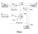
- Fig. 6 shows a circuit diagram of the driving circuit of the present invention.
- the nebulizing driving apparatus 10 further comprises a power processing supply circuit 108.
- the driving circuit 102 comprises a first resistor 10202, a first diode 10204, a first transistor 10206, a first inductor 10208, a second resistor 10210, a third resistor 10212, a second diode 10214, a first capacitor 10216 and a second capacitor 10218.
- the first resistor 10202 is electrically connected to the piezoelectric material 202 and the voltage detection sub-circuit 10602.
- the first diode 10204 is electrically connected to the piezoelectric material 202 and the first resistor 10202.
- the first transistor 10206 is electrically connected to the piezoelectric material 202, the first resistor 10202 and the first diode 10204.
- the first inductor 10208 is electrically connected to the piezoelectric material 202, the first resistor 10202, the first diode 10204 and the first transistor 10206.
- the second resistor 10210 is electrically connected to the first transistor 10206.
- the third resistor 10212 is electrically connected to the first transistor 10206, the second resistor 10210 and the control circuit 104.
- the second diode 10214 is electrically connected to the first inductor 10208 and the power processing supply circuit 108.
- the first capacitor 10216 is electrically connected to the second diode 10214 and the power processing supply circuit 108.
- the second capacitor 10218 is electrically connected to the second diode 10214, the power processing supply circuit 108 and the first capacitor 10216.
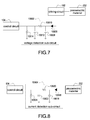
- Fig. 7 shows a circuit diagram of the voltage detection sub-circuit of the present invention.
- the voltage detection sub-circuit 10602 comprises a third diode 10606, a third capacitor 10608, a fourth resistor 10610, a fourth capacitor 10612 and a fifth resistor 10614.
- the third diode 10606 is electrically connected to the driving circuit 102.
- the third capacitor 10608 is electrically connected to the third diode 10606.
- the fourth resistor 10610 is electrically connected to the third diode 10606, the third capacitor 10608 and the control circuit 104.
- the fourth capacitor 10612 is electrically connected to the fourth resistor 10610 and the control circuit 104.
- the fifth resistor 10614 is electrically connected to the fourth resistor 10610, the control circuit 104 and the fourth capacitor 10612.
- Fig. 8 shows a circuit diagram of the current detection sub-circuit of the present invention.
- the current detection sub-circuit 10604 comprises a fourth diode 10616, a fifth capacitor 10618, a sixth resistor 10620, a sixth capacitor 10622 and a seventh resistor 10624.
- the fourth diode 10616 is electrically connected to the piezoelectric material 202.
- the fifth capacitor 10618 is electrically connected to the fourth diode 10616.
- the sixth resistor 10620 is electrically connected to the fourth diode 10616, the fifth capacitor 10618 and the control circuit 104.
- the sixth capacitor 10622 is electrically connected to the sixth resistor 10620 and the control circuit 104.
- the seventh resistor 10624 is electrically connected to the sixth resistor 10620, the control circuit 104 and the sixth capacitor 10622.
- Fig. 9 shows a voltage waveform diagram of the nebulizer which is not operated with the working frequency of the present invention.
- Fig. 10 shows a voltage waveform diagram of the nebulizer which is operated with the working frequency of the present invention.
- the voltage waveform has depressions, so that the nebulizing effect is not good.
- the voltage waveform does not have depressions, so that the nebulizing effect is good.
Landscapes
- Reciprocating Pumps (AREA)
- Special Spraying Apparatus (AREA)
Description
- The present invention relates to a driving apparatus and a system, and especially relates to a nebulizing driving apparatus and a nebulizing system.
- A nebulizer is a very common electronic apparatus. A related art nebulizer comprises a liquid chamber, a piezoelectric material and a driving circuit. The liquid chamber is connected to the piezoelectric material. The driving circuit is electrically connected to the piezoelectric material. The liquid chamber is used for containing liquid, for example medicinal liquid. The driving circuit is used for driving the piezoelectric material. Liquid in the liquid chamber is nebulized when the driving circuit drives the piezoelectric material. The working frequency of the nebulizer (namely, the frequency which the driving circuit drives the piezoelectric material) is usually between 100 KHz to 150 KHz.
- The related art nebulizer comprises following disadvantages:
- 1. The working frequencies of the most of the nebulizers are set when the nebulizers have been manufactured. In another word, the working frequencies of the nebulizers are fixed. However, the characteristics of each of the piezoelectric materials are different. Therefore, the nebulizing effect cannot be optimized if the working frequencies of all of the nebulizers are fixed. The working frequencies of some of the nebulizers are adjustable by variable resistors. However, this method is not accurate, so that the nebulizing effect of the nebulizer still cannot be optimized.
- 2. The whole nebulizer has to be abandoned when the piezoelectric material of the nebulizer is damaged.
- 3. The nebulizer does not automatically detect whether liquid in the liquid chamber is exhausted or not. The nebulizer is damaged easily and energy is wasted when liquid in the liquid chamber is exhausted but the nebulizer is still working.
- In order to solve the above-mentioned problems, an object of the present invention is to provide a nebulizing driving apparatus.
- In order to solve the above-mentioned problems, another object of the present invention is to provide a nebulizing system.
- In order to achieve the object of the present invention mentioned above, the nebulizing driving apparatus is used to drive a piezoelectric material of a nebulizing module. The nebulizing driving apparatus comprises a driving circuit, a control circuit and a feedback circuit. The driving circuit is electrically connected to the piezoelectric material. The control circuit is electrically connected to the driving circuit. The feedback circuit is electrically connected to the driving circuit, the control circuit and the piezoelectric material. The feedback circuit detects an electrical data fed back from the piezoelectric material and sends the electrical data to the control circuit when the control circuit is configured to control the driving circuit to drive the piezoelectric material with a driving frequency. According to the electrical data, the control circuit is configured to control the driving circuit to drive the piezoelectric material with a working frequency.
- Moreover, the nebulizing module further comprises a liquid chamber connected to the piezoelectric material. A liquid in the liquid chamber is nebulized when the driving circuit drives the piezoelectric material.
- Moreover, the feedback circuit detects a plurality of the electrical data fed back from the piezoelectric material in accordance with a plurality of different driving frequencies and sends the electrical data to the control circuit when the control circuit is configured to control the driving circuit to drive the piezoelectric material with the different driving frequencies. According to the electrical data, the control circuit is configured to determine the working frequency.
- Moreover, the control circuit selects the driving frequency in accordance with a maximum of the electrical data as the working frequency.
- Moreover, the control circuit selects a current driving frequency as the working frequency when the electrical data in accordance with the current driving frequency is greater than the electrical data in accordance with a previous driving frequency and is greater than the electrical data in accordance with a next driving frequency. The next driving frequency is greater than the current driving frequency. The current driving frequency is greater than the previous driving frequency.
- Moreover, the electrical data in accordance with the working frequency is a maximum of a plurality of current values when the electrical data are the current values.
- Moreover, the electrical data in accordance with the working frequency is a maximum of a plurality of voltage values when the electrical data are the voltage values.
- Moreover, the control circuit calculates a plurality of current values multiplied by a plurality of voltage values in accordance with the current values respectively to obtain a plurality of power values when the electrical data are the current values and the voltage values in accordance with the current values. The control circuit selects the driving frequency in accordance with a maximum of the power values as the working frequency.
- Moreover, after the control circuit controls the driving circuit to drive the piezoelectric material with the working frequency, if the feedback circuit detects that the electrical data fed back from the piezoelectric material is less than or greater than the maximum of the electrical data an offset over a predetermined time, the control circuit controls the driving circuit to stop driving the piezoelectric material. For example, if the maximum of the electrical data is 1 and the offset is 0.1 and the predetermined time is 2 seconds, the piezoelectric material won't be driven if the electrical data fed back from the piezoelectric material is less than 0.9 or greater than 1.1 over 2 seconds.
- Moreover, the feedback circuit comprises a voltage detection sub-circuit and a current detection sub-circuit. The voltage detection sub-circuit is electrically connected to the driving circuit, the control circuit and the piezoelectric material. The current detection sub-circuit is electrically connected to the control circuit and the piezoelectric material.
- In order to achieve another object of the present invention mentioned above, the nebulizing system comprises a nebulizing driving apparatus and a nebulizing module electrically connected to the nebulizing driving apparatus. The nebulizing module comprises a piezoelectric material electrically connected to the nebulizing driving apparatus. The nebulizing driving apparatus comprises a driving circuit, a control circuit and a feedback circuit. The driving circuit is electrically connected to the piezoelectric material. The control circuit is electrically connected to the driving circuit. The feedback circuit is electrically connected to the driving circuit, the control circuit and the piezoelectric material. The feedback circuit detects an electrical data fed back from the piezoelectric material and sends the electrical data to the control circuit when the control circuit is configured to control the driving circuit to drive the piezoelectric material with a driving frequency. According to the electrical data, the control circuit is configured to control the driving circuit to drive the piezoelectric material with a working frequency.
- Moreover, the nebulizing module further comprises a liquid chamber connected to the piezoelectric material. A liquid in the liquid chamber is nebulized when the driving circuit drives the piezoelectric material.
- Moreover, the feedback circuit detects a plurality of the electrical data fed back from the piezoelectric material in accordance with a plurality of different driving frequencies and sends the electrical data to the control circuit when the control circuit is configured to control the driving circuit to drive the piezoelectric material with the different driving frequencies. According to the electrical data, the control circuit is configured to determine the working frequency.
- Moreover, the control circuit selects the driving frequency in accordance with a maximum of the electrical data as the working frequency.
- Moreover, the control circuit selects a current driving frequency as the working frequency when the electrical data in accordance with the current driving frequency is greater than the electrical data in accordance with a previous driving frequency and is greater than the electrical data in accordance with a next driving frequency. The next driving frequency is greater than the current driving frequency. The current driving frequency is greater than the previous driving frequency.
- The advantages of the present invention comprise:
- 1. The working frequency of the nebulizer is traced and adjusted automatically, so that the nebulizing effect of the nebulizer is optimized.
- 2. Only the old nebulizing module is replaced by a new nebulizing module when the piezoelectric material of the nebulizer is damaged. The whole nebulizer does not need to be abandoned. As for the new nebulizing module, the working frequency of the nebulizer is adjusted automatically, so that the nebulizing effect of the nebulizer is optimized.
- 3. When liquid in the liquid chamber is exhausted, the nebulizer will shut down automatically to save energy and protect the nebulizer.
-
-
Fig. 1 shows a block diagram of the nebulizing driving apparatus of the present invention. -
Fig. 2 shows an assembly drawing of the nebulizing driving apparatus of the present invention. -
Fig. 3 shows a waveform diagram of an embodiment of the electrical data versus the driving frequencies of the present invention. -
Fig. 4 shows a block diagram of the nebulizing system of the present invention. -
Fig. 5 shows an assembly drawing of the nebulizing system of the present invention. -
Fig. 6 shows a circuit diagram of the driving circuit of the present invention. -
Fig. 7 shows a circuit diagram of the voltage detection sub-circuit of the present invention. -
Fig. 8 shows a circuit diagram of the current detection sub-circuit of the present invention. -
Fig. 9 shows a voltage waveform diagram of the nebulizer which is not operated with the working frequency of the present invention. -
Fig. 10 shows a voltage waveform diagram of the nebulizer which is operated with the working frequency of the present invention. -
Fig. 11 shows a waveform diagram of another embodiment of the electrical data versus the driving frequencies of the present invention. - Please refer to following detailed description and figures for the technical content of the present invention. The following detailed description and figures are referred for the present invention, but the present invention is not limited to it.
-
Fig. 1 shows a block diagram of the nebulizing driving apparatus of the present invention.Fig. 2 shows an assembly drawing of the nebulizing driving apparatus of the present invention. Anebulizing driving apparatus 10 is used to drive apiezoelectric material 202 of anebulizing module 20. Thenebulizing module 20 comprises thepiezoelectric material 202 and aliquid chamber 204. Thenebulizing driving apparatus 10 comprises a drivingcircuit 102, acontrol circuit 104 and afeedback circuit 106. Thefeedback circuit 106 comprises avoltage detection sub-circuit 10602 and acurrent detection sub-circuit 10604. - The
nebulizing module 20 is electrically connected to thenebulizing driving apparatus 10. Thepiezoelectric material 202 is electrically connected to thenebulizing driving apparatus 10. The drivingcircuit 102 is electrically connected to thepiezoelectric material 202. Thecontrol circuit 104 is electrically connected to thedriving circuit 102. Thefeedback circuit 106 is electrically connected to thedriving circuit 102, thecontrol circuit 104 and thepiezoelectric material 202. Theliquid chamber 204 is connected to thepiezoelectric material 202. Thevoltage detection sub-circuit 10602 is electrically connected to thedriving circuit 102, thecontrol circuit 104 and thepiezoelectric material 202. Thecurrent detection sub-circuit 10604 is electrically connected to thecontrol circuit 104 and thepiezoelectric material 202. - The main feature of the present invention is that the
feedback circuit 106 detects anelectrical data 206 fed back from thepiezoelectric material 202 and sends theelectrical data 206 to thecontrol circuit 104 when thecontrol circuit 104 is configured to control the drivingcircuit 102 to drive thepiezoelectric material 202 with a driving frequency. According to theelectrical data 206, thecontrol circuit 104 is configured to control the drivingcircuit 102 to drive thepiezoelectric material 202 with a working frequency. A liquid in theliquid chamber 204 is nebulized when the drivingcircuit 102 drives thepiezoelectric material 202. - Following content introduces how to find out the working frequency. The
feedback circuit 106 detects a plurality of theelectrical data 206 fed back from thepiezoelectric material 202 in accordance with a plurality of different driving frequencies and sends theelectrical data 206 to thecontrol circuit 104 when thecontrol circuit 104 is configured to control the drivingcircuit 102 to drive thepiezoelectric material 202 with the different driving frequencies. According to theelectrical data 206, thecontrol circuit 104 is configured to determine the working frequency. For example, thecontrol circuit 104 selects the driving frequency in accordance with a maximum of theelectrical data 206 as the working frequency. -
Fig. 3 shows a waveform diagram of an embodiment of the electrical data versus the driving frequencies of the present invention. Theelectrical data 206 can be voltage values, current values or power values. In an embodiment, when thenebulizing driving apparatus 10 is booted up, thecontrol circuit 104 is configured to control the drivingcircuit 102 to drive thepiezoelectric material 202 with a first frequency to a ninth frequency respectively (namely, the first frequency, a second frequency, a third frequency, a fourth frequency, a fifth frequency, a sixth frequency, a seventh frequency, an eighth frequency and the ninth frequency), so that thefeedback circuit 106 detects a plurality of theelectrical data 206 fed back from thepiezoelectric material 202 in accordance with the first frequency to the ninth frequency respectively. Thefeedback circuit 106 informs thecontrol circuit 104 of theelectrical data 206. Thecontrol circuit 104 selects the driving frequency in accordance with the maximum of theelectrical data 206 as the working frequency. As shown inFig. 3 , thecontrol circuit 104 selects the fifth frequency as the working frequency. After the working frequency is selected, thecontrol circuit 104 is configured to control the drivingcircuit 102 to drive thepiezoelectric material 202 with the working frequency, so that the liquid in theliquid chamber 204 is nebulized. -
Fig. 11 shows a waveform diagram of another embodiment of the electrical data versus the driving frequencies of the present invention. The voltage multiplied by the current equals the power. The voltage and the current have an inverse relationship when the power is fixed. InFig. 11 , thecontrol circuit 104 selects the driving frequency in accordance with a minimum of theelectrical data 206 as the working frequency. As shown inFig. 11 , thecontrol circuit 104 selects the fifth frequency as the working frequency. In another word, the present invention is to find out an extreme value (namely, the maximum and the minimum mentioned above). The extreme value is at a slope turning point, such as the fifth frequency shown inFig. 3 (the slope changes from positive to negative) orFig. 11 (the slope changes from negative to positive). - In an embodiment, the
control circuit 104 selects a current driving frequency (for example, the fifth frequency) as the working frequency when theelectrical data 206 in accordance with the current driving frequency (namely, the fifth frequency) is greater than theelectrical data 206 in accordance with a previous driving frequency (for example, the fourth frequency) and is greater than theelectrical data 206 in accordance with a next driving frequency (for example, the sixth frequency). The next driving frequency (namely, the sixth frequency) is greater than the current driving frequency (namely, the fifth frequency). The current driving frequency (namely, the fifth frequency) is greater than the previous driving frequency (namely, the fourth frequency). - The
electrical data 206 in accordance with the working frequency is a maximum of a plurality of current values when theelectrical data 206 are the current values. Theelectrical data 206 in accordance with the working frequency is a maximum of a plurality of voltage values when theelectrical data 206 are the voltage values. Thecontrol circuit 104 calculates a plurality of current values multiplied by a plurality of voltage values in accordance with the current values respectively to obtain a plurality of power values when theelectrical data 206 are the current values and the voltage values in accordance with the current values. Thecontrol circuit 104 selects the driving frequency in accordance with a maximum of the power values as the working frequency. - Following content introduces how the present invention automatically detects whether the liquid in the
liquid chamber 204 is exhausted or not. After thecontrol circuit 104 controls the drivingcircuit 102 to drive thepiezoelectric material 202 with the working frequency, if thefeedback circuit 106 detects that theelectrical data 206 fed back from thepiezoelectric material 202 is less than or greater than the maximum of theelectrical data 206 an offset over a predetermined time, thecontrol circuit 104 controls the drivingcircuit 102 to stop driving thepiezoelectric material 202. For example, if the maximum of theelectrical data 206 is 1 and the offset is 0.1 and the predetermined time is 2 seconds, thepiezoelectric material 202 won't be driven if theelectrical data 206 fed back from thepiezoelectric material 202 is less than 0.9 or greater than 1.1 over 2 seconds. Thenebulizing driving apparatus 10 even shuts down. This is because after thedriving circuit 102 drives thepiezoelectric material 202 with the working frequency, theelectrical data 206 fed back from thepiezoelectric material 202 shall approach the maximum of theelectrical data 206. Therefore, once the offset is too large and over the predetermined time, the liquid in theliquid chamber 204 is determined as being exhausted. -
Fig. 4 shows a block diagram of the nebulizing system of the present invention.Fig. 5 shows an assembly drawing of the nebulizing system of the present invention. Anebulizing system 30 comprises anebulizing driving apparatus 10 and anebulizing module 20. Thenebulizing module 20 comprises apiezoelectric material 202 and aliquid chamber 204. Thenebulizing driving apparatus 10 comprises a drivingcircuit 102, acontrol circuit 104 and afeedback circuit 106. Thefeedback circuit 106 comprises avoltage detection sub-circuit 10602 and acurrent detection sub-circuit 10604. - The
nebulizing module 20 is electrically connected to thenebulizing driving apparatus 10. Thepiezoelectric material 202 is electrically connected to thenebulizing driving apparatus 10. The drivingcircuit 102 is electrically connected to thepiezoelectric material 202. Thecontrol circuit 104 is electrically connected to thedriving circuit 102. Thefeedback circuit 106 is electrically connected to thedriving circuit 102, thecontrol circuit 104 and thepiezoelectric material 202. Theliquid chamber 204 is connected to thepiezoelectric material 202. Thevoltage detection sub-circuit 10602 is electrically connected to thedriving circuit 102, thecontrol circuit 104 and thepiezoelectric material 202. Thecurrent detection sub-circuit 10604 is electrically connected to thecontrol circuit 104 and thepiezoelectric material 202. - The main feature of the present invention is that the
feedback circuit 106 detects anelectrical data 206 fed back from thepiezoelectric material 202 and sends theelectrical data 206 to thecontrol circuit 104 when thecontrol circuit 104 is configured to control the drivingcircuit 102 to drive thepiezoelectric material 202 with a driving frequency. According to theelectrical data 206, thecontrol circuit 104 is configured to control the drivingcircuit 102 to drive thepiezoelectric material 202 with a working frequency. A liquid in theliquid chamber 204 is nebulized when the drivingcircuit 102 drives thepiezoelectric material 202. - Following content introduces how to find out the working frequency. The
feedback circuit 106 detects a plurality of theelectrical data 206 fed back from thepiezoelectric material 202 in accordance with a plurality of different driving frequencies and sends theelectrical data 206 to thecontrol circuit 104 when thecontrol circuit 104 is configured to control the drivingcircuit 102 to drive thepiezoelectric material 202 with the different driving frequencies. According to theelectrical data 206, thecontrol circuit 104 is configured to determine the working frequency. For example, thecontrol circuit 104 selects the driving frequency in accordance with a maximum of theelectrical data 206 as the working frequency. -
Fig. 3 shows a waveform diagram of an embodiment of the electrical data versus the driving frequencies of the present invention. Theelectrical data 206 can be voltage values, current values or power values. In an embodiment, when thenebulizing driving apparatus 10 is booted up, thecontrol circuit 104 is configured to control the drivingcircuit 102 to drive thepiezoelectric material 202 with a first frequency to a ninth frequency respectively (namely, the first frequency, a second frequency, a third frequency, a fourth frequency, a fifth frequency, a sixth frequency, a seventh frequency, an eighth frequency and the ninth frequency), so that thefeedback circuit 106 detects a plurality of theelectrical data 206 fed back from thepiezoelectric material 202 in accordance with the first frequency to the ninth frequency respectively. Thefeedback circuit 106 informs thecontrol circuit 104 of theelectrical data 206. Thecontrol circuit 104 selects the driving frequency in accordance with the maximum of theelectrical data 206 as the working frequency. As shown inFig. 3 , thecontrol circuit 104 selects the fifth frequency as the working frequency. After the working frequency is selected, thecontrol circuit 104 is configured to control the drivingcircuit 102 to drive thepiezoelectric material 202 with the working frequency, so that the liquid in theliquid chamber 204 is nebulized. -
Fig. 11 shows a waveform diagram of another embodiment of the electrical data versus the driving frequencies of the present invention. The voltage multiplied by the current equals the power. The voltage and the current have an inverse relationship when the power is fixed. InFig. 11 , thecontrol circuit 104 selects the driving frequency in accordance with a minimum of theelectrical data 206 as the working frequency. As shown inFig. 11 , thecontrol circuit 104 selects the fifth frequency as the working frequency. In another word, the present invention is to find out an extreme value (namely, the maximum and the minimum mentioned above). The extreme value is at a slope turning point, such as the fifth frequency shown inFig. 3 (the slope changes from positive to negative) orFig. 11 (the slope changes from negative to positive). - In an embodiment, the
control circuit 104 selects a current driving frequency (for example, the fifth frequency) as the working frequency when theelectrical data 206 in accordance with the current driving frequency (namely, the fifth frequency) is greater than theelectrical data 206 in accordance with a previous driving frequency (for example, the fourth frequency) and is greater than theelectrical data 206 in accordance with a next driving frequency (for example, the sixth frequency). The next driving frequency (namely, the sixth frequency) is greater than the current driving frequency (namely, the fifth frequency). The current driving frequency (namely, the fifth frequency) is greater than the previous driving frequency (namely, the fourth frequency). - The
electrical data 206 in accordance with the working frequency is a maximum of a plurality of current values when theelectrical data 206 are the current values. Theelectrical data 206 in accordance with the working frequency is a maximum of a plurality of voltage values when theelectrical data 206 are the voltage values. Thecontrol circuit 104 calculates a plurality of current values multiplied by a plurality of voltage values in accordance with the current values respectively to obtain a plurality of power values when theelectrical data 206 are the current values and the voltage values in accordance with the current values. Thecontrol circuit 104 selects the driving frequency in accordance with a maximum of the power values as the working frequency. - Following content introduces how the present invention automatically detects whether the liquid in the
liquid chamber 204 is exhausted or not. After thecontrol circuit 104 controls the drivingcircuit 102 to drive thepiezoelectric material 202 with the working frequency, if thefeedback circuit 106 detects that theelectrical data 206 fed back from thepiezoelectric material 202 is less than or greater than the maximum of theelectrical data 206 an offset over a predetermined time, thecontrol circuit 104 controls the drivingcircuit 102 to stop driving thepiezoelectric material 202. For example, if the maximum of theelectrical data 206 is 1 and the offset is 0.1 and the predetermined time is 2 seconds, thepiezoelectric material 202 won't be driven if theelectrical data 206 fed back from thepiezoelectric material 202 is less than 0.9 or greater than 1.1 over 2 seconds. Thenebulizing driving apparatus 10 even shuts down. This is because after thedriving circuit 102 drives thepiezoelectric material 202 with the working frequency, theelectrical data 206 fed back from thepiezoelectric material 202 shall approach the maximum of theelectrical data 206. Therefore, once the offset is too large and over the predetermined time, the liquid in theliquid chamber 204 is determined as being exhausted. -
Fig. 6 shows a circuit diagram of the driving circuit of the present invention. Thenebulizing driving apparatus 10 further comprises a powerprocessing supply circuit 108. The drivingcircuit 102 comprises afirst resistor 10202, afirst diode 10204, afirst transistor 10206, afirst inductor 10208, asecond resistor 10210, athird resistor 10212, asecond diode 10214, afirst capacitor 10216 and asecond capacitor 10218. - The
first resistor 10202 is electrically connected to thepiezoelectric material 202 and thevoltage detection sub-circuit 10602. Thefirst diode 10204 is electrically connected to thepiezoelectric material 202 and thefirst resistor 10202. Thefirst transistor 10206 is electrically connected to thepiezoelectric material 202, thefirst resistor 10202 and thefirst diode 10204. Thefirst inductor 10208 is electrically connected to thepiezoelectric material 202, thefirst resistor 10202, thefirst diode 10204 and thefirst transistor 10206. Thesecond resistor 10210 is electrically connected to thefirst transistor 10206. Thethird resistor 10212 is electrically connected to thefirst transistor 10206, thesecond resistor 10210 and thecontrol circuit 104. Thesecond diode 10214 is electrically connected to thefirst inductor 10208 and the powerprocessing supply circuit 108. Thefirst capacitor 10216 is electrically connected to thesecond diode 10214 and the powerprocessing supply circuit 108. Thesecond capacitor 10218 is electrically connected to thesecond diode 10214, the powerprocessing supply circuit 108 and thefirst capacitor 10216. -
Fig. 7 shows a circuit diagram of the voltage detection sub-circuit of the present invention. Thevoltage detection sub-circuit 10602 comprises athird diode 10606, athird capacitor 10608, afourth resistor 10610, afourth capacitor 10612 and afifth resistor 10614. - The
third diode 10606 is electrically connected to thedriving circuit 102. Thethird capacitor 10608 is electrically connected to thethird diode 10606. Thefourth resistor 10610 is electrically connected to thethird diode 10606, thethird capacitor 10608 and thecontrol circuit 104. Thefourth capacitor 10612 is electrically connected to thefourth resistor 10610 and thecontrol circuit 104. Thefifth resistor 10614 is electrically connected to thefourth resistor 10610, thecontrol circuit 104 and thefourth capacitor 10612. -
Fig. 8 shows a circuit diagram of the current detection sub-circuit of the present invention. Thecurrent detection sub-circuit 10604 comprises afourth diode 10616, afifth capacitor 10618, asixth resistor 10620, asixth capacitor 10622 and aseventh resistor 10624. - The
fourth diode 10616 is electrically connected to thepiezoelectric material 202. Thefifth capacitor 10618 is electrically connected to thefourth diode 10616. Thesixth resistor 10620 is electrically connected to thefourth diode 10616, thefifth capacitor 10618 and thecontrol circuit 104. Thesixth capacitor 10622 is electrically connected to thesixth resistor 10620 and thecontrol circuit 104. Theseventh resistor 10624 is electrically connected to thesixth resistor 10620, thecontrol circuit 104 and thesixth capacitor 10622. -
Fig. 9 shows a voltage waveform diagram of the nebulizer which is not operated with the working frequency of the present invention.Fig. 10 shows a voltage waveform diagram of the nebulizer which is operated with the working frequency of the present invention. As shown inFig. 9 , the voltage waveform has depressions, so that the nebulizing effect is not good. As shown inFig. 10 , the voltage waveform does not have depressions, so that the nebulizing effect is good. - The advantages of the present invention comprise:
- 1. The working frequency of the nebulizer is traced and adjusted automatically, so that the nebulizing effect of the nebulizer is optimized.
- 2. Only the old nebulizing module is replaced by a new nebulizing module when the piezoelectric material of the nebulizer is damaged. The whole nebulizer does not need to be abandoned. As for the new nebulizing module, the working frequency of the nebulizer is adjusted automatically, so that the nebulizing effect of the nebulizer is optimized.
- 3. When liquid in the liquid chamber is exhausted, the nebulizer will shut down automatically to save energy and protect the nebulizer.
Claims (15)
- A nebulizing driving apparatus (10) used to drive a piezoelectric material (202) of a nebulizing module (20), the nebulizing driving apparatus (10) comprising:a driving circuit (102) electrically connected to the piezoelectric material (202);a control circuit (104) electrically connected to the driving circuit (102); anda feedback circuit (106) electrically connected to the driving circuit (102), the control circuit (104) and the piezoelectric material (202),wherein the feedback circuit (106) detects an electrical data (206) fed back from the piezoelectric material (202) and sends the electrical data (206) to the control circuit (104) when the control circuit (104) is configured to control the driving circuit (102) to drive the piezoelectric material (202) with a driving frequency; according to the electrical data (206), the control circuit (104) is configured to control the driving circuit (102) to drive the piezoelectric material (202) with a working frequency.
- The nebulizing driving apparatus (10) in claim 1, wherein the nebulizing module (20) further comprises a liquid chamber (204) connected to the piezoelectric material (202); a liquid in the liquid chamber (204) is nebulized when the driving circuit (102) drives the piezoelectric material (202).
- The nebulizing driving apparatus (10) in claim 1, wherein the feedback circuit (106) detects a plurality of the electrical data (206) fed back from the piezoelectric material (202) in accordance with a plurality of different driving frequencies and sends the electrical data (206) to the control circuit (104) when the control circuit (104) is configured to control the driving circuit (102) to drive the piezoelectric material (202) with the different driving frequencies; according to the electrical data (206), the control circuit (104) is configured to determine the working frequency.
- The nebulizing driving apparatus (10) in claim 3, wherein the control circuit (104) selects the driving frequency in accordance with a maximum of the electrical data (206) as the working frequency.
- The nebulizing driving apparatus (10) in claim 4, wherein the control circuit (104) selects a current driving frequency as the working frequency when the electrical data (206) in accordance with the current driving frequency is greater than the electrical data (206) in accordance with a previous driving frequency and is greater than the electrical data (206) in accordance with a next driving frequency; the next driving frequency is greater than the current driving frequency; the current driving frequency is greater than the previous driving frequency.
- The nebulizing driving apparatus (10) in claim 5, wherein the electrical data (206) in accordance with the working frequency is a maximum of a plurality of current values when the electrical data (206) are the current values.
- The nebulizing driving apparatus (10) in claim 5, wherein the electrical data (206) in accordance with the working frequency is a maximum of a plurality of voltage values when the electrical data (206) are the voltage values.
- The nebulizing driving apparatus (10) in claim 5, wherein the control circuit (104) calculates a plurality of current values multiplied by a plurality of voltage values in accordance with the current values respectively to obtain a plurality of power values when the electrical data (206) are the current values and the voltage values in accordance with the current values; the control circuit (104) selects the driving frequency in accordance with a maximum of the power values as the working frequency.
- The nebulizing driving apparatus (10) in claim 5, wherein after the control circuit (104) controls the driving circuit (102) to drive the piezoelectric material (202) with the working frequency, if the feedback circuit (106) detects that the electrical data (206) fed back from the piezoelectric material (202) is less than or greater than the maximum of the electrical data (206) an offset over a predetermined time, the control circuit (104) controls the driving circuit (102) to stop driving the piezoelectric material (202).
- The nebulizing driving apparatus (10) in claim 5, wherein the feedback circuit (106) comprises:a voltage detection sub-circuit (10602) electrically connected to the driving circuit (102), the control circuit (104) and the piezoelectric material (202); anda current detection sub-circuit (10604) electrically connected to the control circuit (104) and the piezoelectric material (202).
- A nebulizing system (30) comprising:a nebulizing driving apparatus (10); anda nebulizing module (20) electrically connected to the nebulizing driving apparatus (10),wherein the nebulizing module (20) comprises:a piezoelectric material (202) electrically connected to the nebulizing driving apparatus (10),wherein the nebulizing driving apparatus (10) comprises:a driving circuit (102) electrically connected to the piezoelectric material (202);a control circuit (104) electrically connected to the driving circuit (102); anda feedback circuit (106) electrically connected to the driving circuit (102), the control circuit (104) and the piezoelectric material (202),wherein the feedback circuit (106) detects an electrical data (206) fed back from the piezoelectric material (202) and sends the electrical data (206) to the control circuit (104) when the control circuit (104) is configured to control the driving circuit (102) to drive the piezoelectric material (202) with a driving frequency; according to the electrical data (206), the control circuit (104) is configured to control the driving circuit (102) to drive the piezoelectric material (202) with a working frequency.
- The nebulizing system (30) in claim 11, wherein the nebulizing module (20) further comprises a liquid chamber (204) connected to the piezoelectric material (202); a liquid in the liquid chamber (204) is nebulized when the driving circuit (102) drives the piezoelectric material (202).
- The nebulizing system (30) in claim 11, wherein the feedback circuit (106) detects a plurality of the electrical data (206) fed back from the piezoelectric material (202) in accordance with a plurality of different driving frequencies and sends the electrical data (206) to the control circuit (104) when the control circuit (104) is configured to control the driving circuit (102) to drive the piezoelectric material (202) with the different driving frequencies; according to the electrical data (206), the control circuit (104) is configured to determine the working frequency.
- The nebulizing system (30) in claim 13, wherein the control circuit (104) selects the driving frequency in accordance with a maximum of the electrical data (206) as the working frequency.
- The nebulizing system (30) in claim 14, wherein the control circuit (104) selects a current driving frequency as the working frequency when the electrical data (206) in accordance with the current driving frequency is greater than the electrical data (206) in accordance with a previous driving frequency and is greater than the electrical data (206) in accordance with a next driving frequency; the next driving frequency is greater than the current driving frequency; the current driving frequency is greater than the previous driving frequency.
Applications Claiming Priority (1)
| Application Number | Priority Date | Filing Date | Title |
|---|---|---|---|
| TW104105228A TWI572412B (en) | 2015-02-16 | 2015-02-16 | Nebulizing driving apparatus and nebulizing system |
Publications (2)
| Publication Number | Publication Date |
|---|---|
| EP3056286A1 true EP3056286A1 (en) | 2016-08-17 |
| EP3056286B1 EP3056286B1 (en) | 2018-10-03 |
Family
ID=54359977
Family Applications (1)
| Application Number | Title | Priority Date | Filing Date |
|---|---|---|---|
| EP15190806.8A Active EP3056286B1 (en) | 2015-02-16 | 2015-10-21 | Nebulizing driving apparatus and nebulizing system |
Country Status (3)
| Country | Link |
|---|---|
| US (1) | US9780286B2 (en) |
| EP (1) | EP3056286B1 (en) |
| TW (1) | TWI572412B (en) |
Citations (4)
| Publication number | Priority date | Publication date | Assignee | Title |
|---|---|---|---|---|
| EP0442510A1 (en) * | 1990-02-14 | 1991-08-21 | Siemens Aktiengesellschaft | Method and apparatus for ultrasonic liquid atomization |
| US20060102172A1 (en) * | 2002-10-30 | 2006-05-18 | Pari Gmbh Spezialisten Fur Effektive Inhalation | Inhalation therapy device |
| EP2047914A1 (en) * | 2007-10-10 | 2009-04-15 | Microflow Engineering SA | Adaptive piezoelectric actuator control system |
| WO2012056398A1 (en) * | 2010-10-29 | 2012-05-03 | Koninklijke Philips Electronics N.V. | A nebulizer, a control unit for controlling the same, and a method of controlling a nebulizer |
Family Cites Families (5)
| Publication number | Priority date | Publication date | Assignee | Title |
|---|---|---|---|---|
| DE69416129T2 (en) * | 1994-10-10 | 1999-07-01 | Endress + Hauser GmbH + Co., 79689 Maulburg | A method for operating an ultrasonic transducer and circuit arrangement for performing the method |
| JP3791485B2 (en) * | 2002-06-04 | 2006-06-28 | 株式会社村田製作所 | Tuning fork vibrator, vibration gyro using the same, electronic device using the same, and method for manufacturing tuning fork vibrator |
| TWI312161B (en) * | 2006-01-05 | 2009-07-11 | Nat Taiwan Universit | Multiple output piezoelectric transformer and inverter |
| CN2905088Y (en) * | 2006-04-10 | 2007-05-30 | 陈清甫 | Portable drug atomized administration device |
| TW200821041A (en) * | 2006-11-07 | 2008-05-16 | Health & Amp Life Co Ltd | Generating system of piezoelectric enable and generating method of the same |
-
2015
- 2015-02-16 TW TW104105228A patent/TWI572412B/en active
- 2015-10-20 US US14/887,798 patent/US9780286B2/en active Active
- 2015-10-21 EP EP15190806.8A patent/EP3056286B1/en active Active
Patent Citations (4)
| Publication number | Priority date | Publication date | Assignee | Title |
|---|---|---|---|---|
| EP0442510A1 (en) * | 1990-02-14 | 1991-08-21 | Siemens Aktiengesellschaft | Method and apparatus for ultrasonic liquid atomization |
| US20060102172A1 (en) * | 2002-10-30 | 2006-05-18 | Pari Gmbh Spezialisten Fur Effektive Inhalation | Inhalation therapy device |
| EP2047914A1 (en) * | 2007-10-10 | 2009-04-15 | Microflow Engineering SA | Adaptive piezoelectric actuator control system |
| WO2012056398A1 (en) * | 2010-10-29 | 2012-05-03 | Koninklijke Philips Electronics N.V. | A nebulizer, a control unit for controlling the same, and a method of controlling a nebulizer |
Also Published As
| Publication number | Publication date |
|---|---|
| TW201630665A (en) | 2016-09-01 |
| US20160240767A1 (en) | 2016-08-18 |
| TWI572412B (en) | 2017-03-01 |
| EP3056286B1 (en) | 2018-10-03 |
| US9780286B2 (en) | 2017-10-03 |
Similar Documents
| Publication | Publication Date | Title |
|---|---|---|
| US10298073B2 (en) | Method and apparatus for controlling wireless induction power supply | |
| CN102032206B (en) | Fan time-delay control system | |
| TWI523417B (en) | RF power supply system and the use of RF power supply system impedance matching method | |
| US10730126B2 (en) | Power supply device for wire electric discharge machining | |
| CN115966453A (en) | Matched source impedance drive system and method of operating the same | |
| CN108631318B (en) | Systems and methods for line voltage drop compensation | |
| CN105262326B (en) | A kind of switch power source output voltage linearly starts control circuit | |
| US7102110B2 (en) | Magnetron oscillating apparatus | |
| JP6553346B2 (en) | Overcurrent detection circuit, USB power supply apparatus using the same, electronic apparatus, overcurrent detection method | |
| US9780286B2 (en) | Nebulizing driving apparatus and nebulizing system | |
| CN105852228B (en) | An electronic cigarette ultrasonic circuit control method and system | |
| CN111060226B (en) | Self-adjusting vibrating wire sensor excitation voltage generation circuit system and control method | |
| US9312754B2 (en) | Power supply apparatus with reducing voltage overshooting | |
| CN104597952B (en) | Voltage stabilizing circuit of alternating current voltage stabilizer | |
| CN105988387B (en) | Spray driving device and spray system | |
| KR20150048635A (en) | Power supply circuit and electronic device with power supply circuit | |
| JP5299989B2 (en) | Ionizer | |
| TWI393336B (en) | Flyback switching power supply and control method thereof | |
| US9831761B2 (en) | Speedy discharging circuit and power supply apparatus with speedy discharging circuit | |
| CN103677048B (en) | A kind of driving circuit and electronic installation | |
| US20120176166A1 (en) | Driver circuit | |
| TWI634730B (en) | Electronic discharge system | |
| CN205160347U (en) | A switching power supply output voltage linear start control circuit | |
| US9641096B2 (en) | Energy-saving power supply apparatus | |
| US9083268B2 (en) | Controlling circuit for fan |
Legal Events
| Date | Code | Title | Description |
|---|---|---|---|
| PUAI | Public reference made under article 153(3) epc to a published international application that has entered the european phase |
Free format text: ORIGINAL CODE: 0009012 |
|
| AK | Designated contracting states |
Kind code of ref document: A1 Designated state(s): AL AT BE BG CH CY CZ DE DK EE ES FI FR GB GR HR HU IE IS IT LI LT LU LV MC MK MT NL NO PL PT RO RS SE SI SK SM TR |
|
| AX | Request for extension of the european patent |
Extension state: BA ME |
|
| 17P | Request for examination filed |
Effective date: 20170111 |
|
| RBV | Designated contracting states (corrected) |
Designated state(s): AL AT BE BG CH CY CZ DE DK EE ES FI FR GB GR HR HU IE IS IT LI LT LU LV MC MK MT NL NO PL PT RO RS SE SI SK SM TR |
|
| GRAP | Despatch of communication of intention to grant a patent |
Free format text: ORIGINAL CODE: EPIDOSNIGR1 |
|
| INTG | Intention to grant announced |
Effective date: 20180525 |
|
| GRAS | Grant fee paid |
Free format text: ORIGINAL CODE: EPIDOSNIGR3 |
|
| GRAA | (expected) grant |
Free format text: ORIGINAL CODE: 0009210 |
|
| AK | Designated contracting states |
Kind code of ref document: B1 Designated state(s): AL AT BE BG CH CY CZ DE DK EE ES FI FR GB GR HR HU IE IS IT LI LT LU LV MC MK MT NL NO PL PT RO RS SE SI SK SM TR |
|
| REG | Reference to a national code |
Ref country code: GB Ref legal event code: FG4D |
|
| REG | Reference to a national code |
Ref country code: CH Ref legal event code: EP Ref country code: AT Ref legal event code: REF Ref document number: 1048049 Country of ref document: AT Kind code of ref document: T Effective date: 20181015 |
|
| REG | Reference to a national code |
Ref country code: DE Ref legal event code: R096 Ref document number: 602015017408 Country of ref document: DE Ref country code: IE Ref legal event code: FG4D |
|
| REG | Reference to a national code |
Ref country code: NL Ref legal event code: MP Effective date: 20181003 |
|
| REG | Reference to a national code |
Ref country code: LT Ref legal event code: MG4D |
|
| REG | Reference to a national code |
Ref country code: AT Ref legal event code: MK05 Ref document number: 1048049 Country of ref document: AT Kind code of ref document: T Effective date: 20181003 |
|
| PG25 | Lapsed in a contracting state [announced via postgrant information from national office to epo] |
Ref country code: NL Free format text: LAPSE BECAUSE OF FAILURE TO SUBMIT A TRANSLATION OF THE DESCRIPTION OR TO PAY THE FEE WITHIN THE PRESCRIBED TIME-LIMIT Effective date: 20181003 |
|
| PG25 | Lapsed in a contracting state [announced via postgrant information from national office to epo] |
Ref country code: FI Free format text: LAPSE BECAUSE OF FAILURE TO SUBMIT A TRANSLATION OF THE DESCRIPTION OR TO PAY THE FEE WITHIN THE PRESCRIBED TIME-LIMIT Effective date: 20181003 Ref country code: IS Free format text: LAPSE BECAUSE OF FAILURE TO SUBMIT A TRANSLATION OF THE DESCRIPTION OR TO PAY THE FEE WITHIN THE PRESCRIBED TIME-LIMIT Effective date: 20190203 Ref country code: BG Free format text: LAPSE BECAUSE OF FAILURE TO SUBMIT A TRANSLATION OF THE DESCRIPTION OR TO PAY THE FEE WITHIN THE PRESCRIBED TIME-LIMIT Effective date: 20190103 Ref country code: NO Free format text: LAPSE BECAUSE OF FAILURE TO SUBMIT A TRANSLATION OF THE DESCRIPTION OR TO PAY THE FEE WITHIN THE PRESCRIBED TIME-LIMIT Effective date: 20190103 Ref country code: CZ Free format text: LAPSE BECAUSE OF FAILURE TO SUBMIT A TRANSLATION OF THE DESCRIPTION OR TO PAY THE FEE WITHIN THE PRESCRIBED TIME-LIMIT Effective date: 20181003 Ref country code: HR Free format text: LAPSE BECAUSE OF FAILURE TO SUBMIT A TRANSLATION OF THE DESCRIPTION OR TO PAY THE FEE WITHIN THE PRESCRIBED TIME-LIMIT Effective date: 20181003 Ref country code: PL Free format text: LAPSE BECAUSE OF FAILURE TO SUBMIT A TRANSLATION OF THE DESCRIPTION OR TO PAY THE FEE WITHIN THE PRESCRIBED TIME-LIMIT Effective date: 20181003 Ref country code: LT Free format text: LAPSE BECAUSE OF FAILURE TO SUBMIT A TRANSLATION OF THE DESCRIPTION OR TO PAY THE FEE WITHIN THE PRESCRIBED TIME-LIMIT Effective date: 20181003 Ref country code: ES Free format text: LAPSE BECAUSE OF FAILURE TO SUBMIT A TRANSLATION OF THE DESCRIPTION OR TO PAY THE FEE WITHIN THE PRESCRIBED TIME-LIMIT Effective date: 20181003 Ref country code: LV Free format text: LAPSE BECAUSE OF FAILURE TO SUBMIT A TRANSLATION OF THE DESCRIPTION OR TO PAY THE FEE WITHIN THE PRESCRIBED TIME-LIMIT Effective date: 20181003 Ref country code: AT Free format text: LAPSE BECAUSE OF FAILURE TO SUBMIT A TRANSLATION OF THE DESCRIPTION OR TO PAY THE FEE WITHIN THE PRESCRIBED TIME-LIMIT Effective date: 20181003 |
|
| PG25 | Lapsed in a contracting state [announced via postgrant information from national office to epo] |
Ref country code: PT Free format text: LAPSE BECAUSE OF FAILURE TO SUBMIT A TRANSLATION OF THE DESCRIPTION OR TO PAY THE FEE WITHIN THE PRESCRIBED TIME-LIMIT Effective date: 20190203 Ref country code: AL Free format text: LAPSE BECAUSE OF FAILURE TO SUBMIT A TRANSLATION OF THE DESCRIPTION OR TO PAY THE FEE WITHIN THE PRESCRIBED TIME-LIMIT Effective date: 20181003 Ref country code: RS Free format text: LAPSE BECAUSE OF FAILURE TO SUBMIT A TRANSLATION OF THE DESCRIPTION OR TO PAY THE FEE WITHIN THE PRESCRIBED TIME-LIMIT Effective date: 20181003 Ref country code: SE Free format text: LAPSE BECAUSE OF FAILURE TO SUBMIT A TRANSLATION OF THE DESCRIPTION OR TO PAY THE FEE WITHIN THE PRESCRIBED TIME-LIMIT Effective date: 20181003 Ref country code: GR Free format text: LAPSE BECAUSE OF FAILURE TO SUBMIT A TRANSLATION OF THE DESCRIPTION OR TO PAY THE FEE WITHIN THE PRESCRIBED TIME-LIMIT Effective date: 20190104 |
|
| REG | Reference to a national code |
Ref country code: CH Ref legal event code: PL |
|
| REG | Reference to a national code |
Ref country code: BE Ref legal event code: MM Effective date: 20181031 |
|
| PG25 | Lapsed in a contracting state [announced via postgrant information from national office to epo] |
Ref country code: LU Free format text: LAPSE BECAUSE OF NON-PAYMENT OF DUE FEES Effective date: 20181021 |
|
| REG | Reference to a national code |
Ref country code: DE Ref legal event code: R097 Ref document number: 602015017408 Country of ref document: DE |
|
| REG | Reference to a national code |
Ref country code: IE Ref legal event code: MM4A |
|
| PG25 | Lapsed in a contracting state [announced via postgrant information from national office to epo] |
Ref country code: DK Free format text: LAPSE BECAUSE OF FAILURE TO SUBMIT A TRANSLATION OF THE DESCRIPTION OR TO PAY THE FEE WITHIN THE PRESCRIBED TIME-LIMIT Effective date: 20181003 |
|
| PLBE | No opposition filed within time limit |
Free format text: ORIGINAL CODE: 0009261 |
|
| STAA | Information on the status of an ep patent application or granted ep patent |
Free format text: STATUS: NO OPPOSITION FILED WITHIN TIME LIMIT |
|
| PG25 | Lapsed in a contracting state [announced via postgrant information from national office to epo] |
Ref country code: MC Free format text: LAPSE BECAUSE OF FAILURE TO SUBMIT A TRANSLATION OF THE DESCRIPTION OR TO PAY THE FEE WITHIN THE PRESCRIBED TIME-LIMIT Effective date: 20181003 Ref country code: LI Free format text: LAPSE BECAUSE OF NON-PAYMENT OF DUE FEES Effective date: 20181031 Ref country code: RO Free format text: LAPSE BECAUSE OF FAILURE TO SUBMIT A TRANSLATION OF THE DESCRIPTION OR TO PAY THE FEE WITHIN THE PRESCRIBED TIME-LIMIT Effective date: 20181003 Ref country code: CH Free format text: LAPSE BECAUSE OF NON-PAYMENT OF DUE FEES Effective date: 20181031 Ref country code: BE Free format text: LAPSE BECAUSE OF NON-PAYMENT OF DUE FEES Effective date: 20181031 Ref country code: SK Free format text: LAPSE BECAUSE OF FAILURE TO SUBMIT A TRANSLATION OF THE DESCRIPTION OR TO PAY THE FEE WITHIN THE PRESCRIBED TIME-LIMIT Effective date: 20181003 Ref country code: SM Free format text: LAPSE BECAUSE OF FAILURE TO SUBMIT A TRANSLATION OF THE DESCRIPTION OR TO PAY THE FEE WITHIN THE PRESCRIBED TIME-LIMIT Effective date: 20181003 Ref country code: EE Free format text: LAPSE BECAUSE OF FAILURE TO SUBMIT A TRANSLATION OF THE DESCRIPTION OR TO PAY THE FEE WITHIN THE PRESCRIBED TIME-LIMIT Effective date: 20181003 |
|
| 26N | No opposition filed |
Effective date: 20190704 |
|
| PG25 | Lapsed in a contracting state [announced via postgrant information from national office to epo] |
Ref country code: IE Free format text: LAPSE BECAUSE OF NON-PAYMENT OF DUE FEES Effective date: 20181021 Ref country code: FR Free format text: LAPSE BECAUSE OF NON-PAYMENT OF DUE FEES Effective date: 20181203 Ref country code: SI Free format text: LAPSE BECAUSE OF FAILURE TO SUBMIT A TRANSLATION OF THE DESCRIPTION OR TO PAY THE FEE WITHIN THE PRESCRIBED TIME-LIMIT Effective date: 20181003 |
|
| PG25 | Lapsed in a contracting state [announced via postgrant information from national office to epo] |
Ref country code: MT Free format text: LAPSE BECAUSE OF NON-PAYMENT OF DUE FEES Effective date: 20181021 |
|
| PGFP | Annual fee paid to national office [announced via postgrant information from national office to epo] |
Ref country code: DE Payment date: 20191008 Year of fee payment: 5 |
|
| PG25 | Lapsed in a contracting state [announced via postgrant information from national office to epo] |
Ref country code: TR Free format text: LAPSE BECAUSE OF FAILURE TO SUBMIT A TRANSLATION OF THE DESCRIPTION OR TO PAY THE FEE WITHIN THE PRESCRIBED TIME-LIMIT Effective date: 20181003 |
|
| PG25 | Lapsed in a contracting state [announced via postgrant information from national office to epo] |
Ref country code: MK Free format text: LAPSE BECAUSE OF NON-PAYMENT OF DUE FEES Effective date: 20181003 Ref country code: CY Free format text: LAPSE BECAUSE OF FAILURE TO SUBMIT A TRANSLATION OF THE DESCRIPTION OR TO PAY THE FEE WITHIN THE PRESCRIBED TIME-LIMIT Effective date: 20181003 Ref country code: HU Free format text: LAPSE BECAUSE OF FAILURE TO SUBMIT A TRANSLATION OF THE DESCRIPTION OR TO PAY THE FEE WITHIN THE PRESCRIBED TIME-LIMIT; INVALID AB INITIO Effective date: 20151021 |
|
| GBPC | Gb: european patent ceased through non-payment of renewal fee |
Effective date: 20191021 |
|
| PG25 | Lapsed in a contracting state [announced via postgrant information from national office to epo] |
Ref country code: GB Free format text: LAPSE BECAUSE OF NON-PAYMENT OF DUE FEES Effective date: 20191021 |
|
| REG | Reference to a national code |
Ref country code: DE Ref legal event code: R119 Ref document number: 602015017408 Country of ref document: DE |
|
| PG25 | Lapsed in a contracting state [announced via postgrant information from national office to epo] |
Ref country code: DE Free format text: LAPSE BECAUSE OF NON-PAYMENT OF DUE FEES Effective date: 20210501 |
|
| PGFP | Annual fee paid to national office [announced via postgrant information from national office to epo] |
Ref country code: IT Payment date: 20250922 Year of fee payment: 11 |