EP3056128A1 - Floor cleaning apparatus - Google Patents
Floor cleaning apparatus Download PDFInfo
- Publication number
- EP3056128A1 EP3056128A1 EP15154518.3A EP15154518A EP3056128A1 EP 3056128 A1 EP3056128 A1 EP 3056128A1 EP 15154518 A EP15154518 A EP 15154518A EP 3056128 A1 EP3056128 A1 EP 3056128A1
- Authority
- EP
- European Patent Office
- Prior art keywords
- floor cleaning
- cleaning head
- floor
- stabiliser
- relative
- Prior art date
- Legal status (The legal status is an assumption and is not a legal conclusion. Google has not performed a legal analysis and makes no representation as to the accuracy of the status listed.)
- Granted
Links
Images



Classifications
-
- A—HUMAN NECESSITIES
- A47—FURNITURE; DOMESTIC ARTICLES OR APPLIANCES; COFFEE MILLS; SPICE MILLS; SUCTION CLEANERS IN GENERAL
- A47L—DOMESTIC WASHING OR CLEANING; SUCTION CLEANERS IN GENERAL
- A47L13/00—Implements for cleaning floors, carpets, furniture, walls, or wall coverings
- A47L13/10—Scrubbing; Scouring; Cleaning; Polishing
- A47L13/20—Mops
- A47L13/22—Mops with liquid-feeding devices
- A47L13/225—Steam mops
-
- A—HUMAN NECESSITIES
- A47—FURNITURE; DOMESTIC ARTICLES OR APPLIANCES; COFFEE MILLS; SPICE MILLS; SUCTION CLEANERS IN GENERAL
- A47L—DOMESTIC WASHING OR CLEANING; SUCTION CLEANERS IN GENERAL
- A47L11/00—Machines for cleaning floors, carpets, furniture, walls, or wall coverings
- A47L11/40—Parts or details of machines not provided for in groups A47L11/02 - A47L11/38, or not restricted to one of these groups, e.g. handles, arrangements of switches, skirts, buffers, levers
- A47L11/4091—Storing or parking devices, arrangements therefor; Means allowing transport of the machine when it is not being used
Definitions
- the present invention relates to a floor cleaning apparatus, such as a steam mop.
- a floor cleaning apparatus having a floor cleaning head with a bottom for facing a floor during cleaning of the floor.
- Such floor cleaning apparatus can be steam mops which comprises a steam permeable pad for wiping the floor.
- the apparatus may be stored in a self-supporting manner with the bottom of the floor cleaning head still facing a floor.
- the weight of the floor cleaning apparatus can compress the pad and the floor cleaning apparatus may susceptible to leaning or tilting from an upright orientation. This means the floor cleaning apparatus can be prone to toppling particularly if the floor cleaning apparatus is positioned on an inclined surface.
- the apparatus includes a handle connected to the floor cleaning head for manoeuvring the apparatus.
- a handle connected to the floor cleaning head for manoeuvring the apparatus.
- DE102011001631 discloses a floor head with legs which deploy from underneath the floor head when the handle is placed in an upright position and lifts the pad up from the floor.
- a problem is that pad attached to the floor head has to fit between the legs and is limited in size. In order to use a larger pad, holes must be cut in the pad to allow the legs to project through but the pad can snag on the legs if the pad is fitted incorrectly.
- a floor cleaning apparatus with a mechanism for helping to reduce the risk of toppling of the apparatus when the apparatus is not in use.
- the mechanism would be unobtrusive when the apparatus is in use.
- a floor cleaning apparatus comprising: a floor cleaning head having a top, a bottom, and a side extending between the top and the bottom, wherein the bottom is for facing a floor during cleaning of the floor; a floor cleaning pad coupled to the bottom of the floor cleaning head; and at least one stabiliser, wherein the, or each, stabiliser is connected to the floor cleaning head and is movable relative to the floor cleaning head from a stowed position to a deployed position at the side of the floor cleaning head for increasing stability of the apparatus.
- the length of the floor cleaning head is increased and this helps increase the stability of the apparatus since it increases the angle over which the apparatus must rotate to move a centre of mass of the apparatus to a position at which the apparatus will topple.
- the floor cleaning apparatus of the present invention is more stable on flat and even inclined surfaces.
- the stabilisers prevent the floor cleaning pad from compressing and tilting the floor cleaning apparatus from an upright position.
- the stabilizer Since the at least one stabilizer moves from a stowed position to a deployed position at the side of the floor cleaning head, the stabilizer will not interfere with the bottom of the cleaning head. This means that the working area of the floor cleaning head in contact with the floor which cleans the floor is bigger. In turn this means that, for example, a pad attached to the floor cleaning head can also be bigger which improves the effectiveness of the floor cleaning apparatus.
- movement of the, or each, stabiliser relative to the floor cleaning head from the stowed position to the deployed position comprises movement of the, or each, stabiliser from the side of the floor cleaning head.
- movement of the, or each, stabiliser relative to the floor cleaning head from the stowed position to the deployed position comprises movement of the, or each, stabiliser through the side of the floor cleaning head.
- the bottom of the floor cleaning head has a surface with one or more parts that lie in a plane.
- movement of the, or each, stabiliser relative to the floor cleaning head from the stowed position to the deployed position comprises movement of the, or each, stabiliser towards the plane.
- the, or each, stabiliser is moveable relative to the floor cleaning head between the stowed position and the deployed position without protruding from the bottom of the floor cleaning head.
- the floor cleaning apparatus comprises a handle connected to the floor cleaning head, and the handle is movable relative to the floor cleaning head from an operative position to a stored position to cause the, or each, stabiliser to move relative to the floor cleaning head from the stowed position to the deployed position.
- the handle is movable relative to the floor cleaning head from the operative position to the stored position without causing the, or each, stabiliser to move relative to the floor cleaning head to the deployed position, when movement of the, or each, stabiliser relative to the floor cleaning head to the deployed position is obstructed.
- the, or each, stabiliser is moveable relative to the floor cleaning head from the deployed position towards the stowed position without causing movement of the handle relative to the floor cleaning head from the stored position.
- the floor cleaning apparatus comprises a mechanism for converting movement of the handle relative to the floor cleaning head from the operative position to the stored position into movement of the, or each, stabiliser relative to the floor cleaning head from the stowed position to the deployed position.
- the mechanism comprises first and second members that are moveable relative to each other so as to absorb movement of the handle from the operative position to the stored position without moving the, or each, stabiliser from the stowed position to the deployed position.
- the mechanism comprises a resilient apparatus that is arranged to bias the first and second members apart.
- the floor cleaning apparatus comprises a lock for fixing the handle in position relative to the floor cleaning head when the handle is at the stored position.
- the handle has a longitudinal axis. Further optionally, the longitudinal axis is closer to ninety degrees to the bottom of the floor cleaning head when the handle is at the stored position than when the handle is at the operative position.
- the floor cleaning apparatus has a centre of mass that is located so that the floor cleaning apparatus is stable when the handle is at the stored position, the, or each, stabiliser is at the deployed position, and the bottom of the floor cleaning head is standing on a surface inclined at an angle.
- the angle may, for example, be fifteen degrees to the horizontal, twenty degrees to the horizontal, or twenty-five degrees to the horizontal.
- the bottom of the floor cleaning head includes one or more connectors for connecting a floor cleaning pad to the bottom of the floor cleaning head.
- the floor cleaning apparatus may comprise a floor cleaning pad for releasable attachment to the bottom of the floor cleaning head via the one or more connectors.
- the floor cleaning apparatus is a steam mop for emitting steam at the bottom of the floor cleaning head.
- the floor cleaning apparatus may comprise a reservoir for holding a volume of water, and a heater for heating the water sufficiently to generate the steam.
- the heater may be electrically-powered.
- the at least one stabiliser extends below the bottom of the floor cleaning head a distance of substantially the thickness of the floor cleaning pad. This means that the floor cleaning pad is in contact with floor when the stabilisers are in contact with the floor. However the stabilisers support the weight of the floor cleaning apparatus if the floor cleaning apparatus experiences a tilting action. This prevents the floor cleaning apparatus from tilting any further. By letting the floor cleaning pad engage the floor, the coefficient of friction between the floor cleaning apparatus and the floor is increased and the floor cleaning apparatus is less likely to slide down an inclined surface.
- FIG. 1 there is shown a schematic side view and a schematic top view of a portion of a floor cleaning apparatus 1 according to an embodiment of the present invention.
- the apparatus 1 is a steam mop, but in other embodiments the apparatus 1 may be other than a steam mop.
- the steam mop of this embodiment will be referred to simply as the apparatus 1.
- the apparatus 1 comprises a floor cleaning head 100, which has a top 111, a bottom 121, and a plurality of sides 130, 140, 150, 160 extending between the top 111 and the bottom 121.
- a floor cleaning pad 120 is coupled to the bottom 121.
- a clamp 110 is coupled to the top 111 of the floor cleaning head 100 by screw fastening or other fastening means.
- the plurality of sides 130, 140, 150, 160 will be referred to herein as a front side 130, a rear side 140, a left side 150, and a right side 160, respectively, of the floor cleaning head 100.
- the floor cleaning head 100 has a length measured between and orthogonal to the front and rear sides 130, 140, and a width measured between and orthogonal to the left and right sides 150, 160.
- the bottom 121 of the floor cleaning head 100 is orientated to face the floor, so that the top 111 and sides 130, 140, 150, 160 of the floor cleaning head 100 are above the bottom 121, and the bottom 121 is located between the floor and the top 111 and sides 130, 140, 150, 160 of the floor cleaning head 100.
- the floor cleaning head 100 comprises a hood 102 that defines the top 111, the bottom 121 and the sides 130, 140, 150, 160 of the floor cleaning head 100.
- the hood 102 is detachable from the floor cleaning pad 120 for servicing the apparatus 1.
- the hood 102 and floor cleaning pad 120 is permanently fixed to each other, or are respective portions of a single unitary component.
- the hood 102 is not shown, in order to make visible interior components of the floor cleaning head 100.
- a hole 123 is formed in the cleaning head to receive a steam conduit (not shown).
- the steam conduit such as a tube is in fluid communication with a steam diffuser (not shown) which is located adjacent to the floor cleaning pad 120.
- the steam diffuser is known to a person skilled in the art and for the purposes for brevity will not be discussed any further.
- a plurality of screw holes 122 extend through the bottom 121 between the interior and exterior of the floor cleaning head 100.
- the screw holes 122 are configured to retaining screws for coupling the floor cleaning pad 120 to the bottom 121.
- the coupling of the floor cleaning pad 120 to the bottom 121 will be discussed in further detail below.
- the apparatus 1 is for arranged to direct steam through the steam conduit and steam diffuser from the interior to the exterior of the floor cleaning head 100, so as to emit the steam at the bottom 121 of the floor cleaning head 100, when the apparatus 1 is being used to clean a floor. Such steam may help to free-up dirt from the floor being cleaned, and may help to disinfect the floor.
- the apparatus 1 has a reservoir (not shown) for holding a volume of water, and a heater (not shown) for heating the water sufficiently to generate the steam.
- the heater is electrically-powered so that passing an electric current through the heater causes the heater to heat up
- the apparatus 1 has an electrical cable (not shown) for connecting the heater to the mains electrical power supply.
- the floor cleaning apparatus 1 is battery powered and the apparatus comprises a rechargeable battery pack.
- the apparatus 1 may be for emitting steam at the bottom 121 of the floor cleaning head 100 in some other manner.
- the bottom 121 comprises a plurality of connectors (not shown) which are mounted on at screw holes 122 for connecting a floor cleaning pad 120, such as a microfibre pad, to the bottom 121 of the floor cleaning head 100.
- a floor cleaning pad 120 such as a microfibre pad
- the connectors are hook or loop portions of a hook-and-loop fastener (e.g. Velcro TM) fastened to the hood 102 by a screw fastener, but in other embodiments the connectors may take a different form or be omitted.
- the floor cleaning pad 120 may comprises a reciprocal hook and loop fastening portion or alternative fastening means.
- the floor cleaning pad 120 may comprise different a plurality of different fibres and may comprise one or more portions 124 with longer fibre lengths or different material.
- the bottom 121 comprises only one connector for connecting a floor cleaning pad 120, such as a microfibre pad, to the bottom 121 of the floor cleaning head 100.
- the apparatus 1 comprises a floor cleaning pad for releasable attachment to the bottom 121 of the floor cleaning head 100.
- the bottom 121 of the floor cleaning head 100 is substantially parallel to the floor.
- the bottom 121 may be planar, or flat.
- the bottom 121 may be non-planar.
- the bottom 121 is planar, at least because the floor cleaning pad 120 is substantially planar and compressible and the bottom 121 is planar in a plane P-P.
- the apparatus 1 also has a handle interface 200 for coupling a handle or floor cleaning apparatus body (not shown).
- the handle interface 200 comprises a slot for receiving the handle and a latch or fastening means secures the handle to the handle interface 200.
- a longitudinal axis of the handle may be coaxial with the longitudinal axis L-L of the handle interface 200.
- the longitudinal axis of the handle may be parallel or substantially parallel to the longitudinal axis L-L of the handle interface 200.
- the handle interface 200 is optional and the handle couples directly to the universal joint.
- the handle interface 200 is connected to the floor cleaning head 100, in this embodiment via a universal joint (now shown) at an end of the handle interface 200.
- the universal joint is coupled to the floor cleaning head via clamp 110.
- the clamp 110 comprises circular recesses for receiving pegs 125 of the universal joint for rotation about the first axis A1-A1.
- the handle interface 200 and the handle are elongate, although only the handle interface 200 is shown in the Figures, and has a longitudinal axis L-L, as indicated in Figure 1 .
- the handle interface 200 is movable relative to the floor cleaning head 100 between an operative position, as shown in Figures 1, 2 and 12 , and a stored position, as shown in Figures 9, 10 and 14 .
- the handle interface 200 is inclined relative to the floor cleaning head 100, so that the longitudinal axis L-L forms an acute angle ⁇ with the plane P-P and the bottom 121.
- the universal joint of the handle interface 200 enables rotation of the handle interface 200 relative to the floor cleaning head 100 about two orthogonal axes A1-A1, A2-A2.
- a first axis A1-A1 of the axes is parallel to the width of the floor cleaning head 100 for permitting up-and-down rotational movement of the handle interface 200 relative to the floor cleaning head 100 to vary the angle ⁇ between the longitudinal axis L-L and the plane P-P.
- a second axis A2-A2 of the axes is orthogonal to the first axis A1-A1 for permitting side-to-side rotational movement of the handle interface 200 relative to the floor cleaning head 100.
- the handle interface 200 may be movably connected to the floor cleaning head 100 by a connection other than a universal joint.
- the longitudinal axis L-L of the handle interface 200 is closer to ninety degrees to the plane P-P and the bottom 121 of the floor cleaning head 100 than when the handle interface 200 is at the operative position. Accordingly, when the handle interface 200 is at the stored position, the handle interface 200 is more upright than when the handle interface 200 is at the operative position, so that the apparatus 1 requires less horizontal space for storage.
- the apparatus 1 has a lock (not shown) for fixing the handle interface 200 in position relative to the floor cleaning head 100 when the handle interface 200 is at the stored position. This helps prevent the handle interface 200 from falling, if the handle interface 200 is knocked inadvertently by a passer-by during storage of the apparatus 1.
- the apparatus when the handle interface 200 is at the stored position, the apparatus may be left to stand in a self-supporting manner with the bottom 121 of the floor cleaning head 100 still facing a floor. However, even though the apparatus 1 is more stable when in this state than when the handle interface 200 is at the operative position, the apparatus 1 still may be knocked inadvertently by a passer-by.
- the apparatus 1 of this embodiment has first and second stabilisers 310, 320.
- the stabilisers 310, 320 are spaced apart in the width direction of the floor cleaning head 100.
- the stabilisers 310, 320 are connected to the floor cleaning head 100 for movement relative to the floor cleaning head 100 from a stowed position, as shown in Figures 1 to 4 and 12 , to a deployed position, as shown in Figures 9 to 11 and 14 , for increasing stability of the apparatus 1.
- each of the stabilisers 310, 320 is movable relative to the floor cleaning head 100 from the stowed position to the deployed position at the front side 130 of the floor cleaning head 100. Therefore, the shape and structure of the bottom 121 of the floor cleaning head 100 need not be dependent on the shape and position of the stabilisers 310, 320, or the mechanism 400, described below, for controlling their movement. Accordingly, the shape of the bottom 121 is able to be made most suitable for floor cleaning and for retaining the floor cleaning pad 120.
- movement of the stabilisers 310, 320 relative to the floor cleaning head 100 from the respective stowed positions to the respective deployed positions comprises movement of the stabiliser 310, 320 from the front side 130 of the floor cleaning head 100. Therefore, if a combination of the stabilisers 310, 320 and the floor cleaning head 100 is considered to be a body, and the body has a length in a direction parallel to the length of the floor cleaning head 100, such movement of the stabilisers 310, 320 increases the length of the body. Such increasing of the length of the body helps to increase stability of the apparatus 1, since it increases the angle over which the apparatus 1 must rotate to move a centre of mass of the apparatus 1 to a position at which the apparatus 1 will topple.
- movement of the stabilisers 310, 320 relative to the floor cleaning head 100 from the respective stowed positions to the respective deployed positions may be in a direction parallel to the front side 130 of the floor cleaning head 100, and may not increase the length of the body.
- movement of the stabilisers 310, 320 relative to the floor cleaning head 100 from the respective stowed positions to the respective deployed positions comprises movement of the stabilisers 310, 320 through the front side 130 of the floor cleaning head 100. More specifically, in this embodiment, when the stabilisers 310, 320 are at their respective stowed positions, at least a majority, and optionally all, of the stabilisers 310, 320 is located at an interior of the floor cleaning head 100. Therefore, the stabilisers 310, 320 are unobtrusive when at their respective stowed positions.
- Movement of the stabilisers 310, 320 to their respective deployed positions results in the stabilisers 310, 320 passing through the front side 130 of the floor cleaning head 100 from the interior of the floor cleaning head 100 to the exterior of the floor cleaning head 100.
- movement of the stabilisers 310, 320 relative to the floor cleaning head 100 from the respective stowed positions to the respective deployed positions comprises movement of the stabilisers 310, 320 between two positions at the exterior of the floor cleaning head 100, and the stabilisers 310, 320 may never pass through a side 130, 140, 150, 160 of the floor cleaning head 100.
- the stabilisers 310, 320 are movable relative to the floor cleaning head 100 between the stowed position and the deployed position without protruding from the bottom 121 of the floor cleaning head 100. Therefore, movement of the stabilisers 310, 320 relative to the floor cleaning head 100 need not cause the apparatus 1 to be lifted from the floor, when the apparatus 1 is standing with the bottom 121 facing the floor, which otherwise could unbalance the apparatus 1 and cause it to topple. Moreover, this avoids the risk of deployment of the stabilisers 310, 320 being hindered or prevented by a floor cleaning pad 120 connected to the bottom 121, in instances when a floor cleaning pad is so connected to the bottom 121.
- Movement of the stabilisers 310, 320 from the side and not the bottom means that the stabilisers do not have to project through the floor cleaning pad 120 and the floor cleaning pad 120 is not required to have holes therein to receive the stabilisers 310, 320.
- the floor cleaning pad 120 can at least cover the entire surface of the bottom 121 and in some embodiments the floor cleaning pad 120 can have an area greater than the area of the bottom 121.
- movement of the stabilisers 310, 320 from their respective stowed positions to their respective deployed positions comprises movement of the stabilisers towards the plane P-P described above. Therefore, during deployment of the stabilisers 310, 320, the stabilisers 310, 320 are moved in the direction of the floor, when the apparatus 1 is standing with the bottom 121 facing the floor. Movement of the stabilisers 310, 320 towards the plane P-P helps to increase stability of the apparatus 1, since it increases the angle over which the apparatus 1 must rotate to move the centre of mass of the apparatus 1 to a position at which the apparatus 1 will topple. Most floors are substantially flat.
- the stabilisers 310, 320 would come into contact with the floor. This helps to reduce the risk of toppling of the apparatus 1 when the apparatus is not in use.
- the stabilisers 310, 320 when the stabilisers 310, 320 are at their respective deployed positions, part of each of the stabiliser 310, 320 is in the plane P-P. Accordingly, when deployed, the stabilisers 310, 320 act to increase the area over which the apparatus 1 contacts a flat floor, when the apparatus 1 is standing with the bottom 121 facing the floor, which further helps to reduce the risk of toppling of the apparatus 1 when the apparatus is not in use.
- the stabilisers 310, 320 are configured to move in a direction which is substantially perpendicular to the plane P-P. This can be seen from comparing Figure 7 with Figure 9 .
- the stabilisers 310, 320 move in a vertical direction at least the thickness of the floor cleaning pad 120 below the bottom 121. If the stabilisers 310,320 only extended to a position in line with the bottom 121, the floor cleaning pad is compressible and can cause tilting of floor cleaning apparatus 1 if the compression of the floor cleaning pad 120 is not uniform (e.g. on one side only). This means that the stabilisers prevent the floor cleaning pad 120 from compressing under the weight of the floor cleaning apparatus 1. In this way the floor cleaning pad 120 cannot compress only on one side which can exaggerate the tilting of the floor cleaning apparatus 1.
- the centre of mass of the apparatus 1 is located so that the apparatus 1 is stable when the following three conditions are met simultaneously: (a) the handle interface 200 is at the stored position, and (b) the stabilisers 310, 320 are at the respective deployed positions.
- the stabilisers 310, 320 increase the stability of the floor cleaning apparatus 1 when the floor cleaning apparatus 1 is resting on a horizontal surface. The inventors have noticed that if conditions (a) and (b) are true, then the stability of the floor cleaning apparatus 1 is such that the floor cleaning apparatus will not topple over when the bottom 121 of the floor cleaning head 100 is standing on a surface inclined at fifteen degrees to the horizontal.
- the centre of mass is modified such that the floor cleaning apparatus 1 does not topple if it receives a knock when all three conditions (a) (b) and (c) are met.
- the centre of mass of the apparatus 1 is located so that the apparatus 1 is stable when the first two conditions are true and the third condition is that the bottom 121 of the floor cleaning head 100 is standing on a surface inclined at more than fifteen degrees to the horizontal, such as twenty degrees to the horizontal or twenty-five degrees to the horizontal.
- the apparatus 1 has a mechanism 400 that is for converting movement of the handle interface 200 relative to the floor cleaning head 100 from the operative position to the stored position into movement of the stabilisers 310, 320 relative to the floor cleaning head 100 from their respective stowed positions to their respective deployed position.
- the mechanism 400 of this embodiment will now be described in more detail with reference to Figure 11 .
- the mechanism 400 comprises a first member 410, a second member 420, a resilient apparatus 430, a first arm 440, a second arm 450, and a torsion spring 460.
- the first member 410 is slidably connected to the second member 420 via the resilient apparatus 430 for movement in a direction parallel to the length of the floor cleaning head 100.
- a front face 411 of the first member 410 is for abutting a lower end of the handle interface 200 on sufficient rotation of the handle interface 200 relative to the floor cleaning head 100 from the operative position, as will be described below.
- the second member 420 is slidably connected to the floor cleaning head 100, and more specifically to the chassis 101, for movement in a direction parallel to the length of the floor cleaning head 100.
- Respective first ends 441, 451 of the first and second arms 440, 450 are rotatably connected to the second frame 420, and respective second ends 442, 452 of the first and second arms 440, 450 are rotatably connected to the respective first and second stabilisers 310, 320.
- the first and second arms 440, 450 are rotatably connected to the floor cleaning head 100, and more specifically to the chassis 101, at respective pivots 445, 455.
- the pivots are between the first and second ends 441, 442, 451, 452 of the first and second arms 440, 450.
- the torsion spring 460 has a first end fixed to the first arm 440 and a second end fixed to the floor cleaning head 100.
- the torsion spring 460 is arranged to bias the first arm 440 to rotate in an anticlockwise direction, as Figure 11 is drawn. Accordingly, the torsion spring 460 biases the first member 410 away from the rear side 140 of the floor cleaning head 100, and thus biases the stabilisers 310, 320 to their respective stowed positions.
- there is another torsion spring such that both the first and second arms 440, 450 are each biased by a torsion spring.
- the first and second arms 440, 450 can be biased by other types of spring, such as a coil spring or a leaf spring or any means suitable for biasing the first and second arms 440, 450.
- the resilient apparatus 430 is arranged to bias the first and second members 410, 420 apart.
- the resilient apparatus 430 comprises two coil springs 431, 432 arranged in parallel. Respective first ends of the coil springs 431, 432 are fixed to the first member 410, and respective second ends of the coil springs 431, 432 are fixed to the second member 420.
- the coil springs 431, 432 are compression coil springs, which are arranged to bias the first and second members 410, 420 apart.
- the coil springs 431, 432 may be tension coil springs, which are arranged to bias the first and second members 410, 420 apart.
- the resilient apparatus 430 may take a different form or be omitted.
- the first member 410 may be immovable relative to, and optionally unitary with, the second frame 420.
- the stabilisers 310, 320 are located in respective channels 171, 172 of the floor cleaning head 100.
- the channels 171, 172 are for constraining the stabilisers 310, 320 to motion relative to the floor cleaning head 100 between their stowed and deployed positions.
- the first stabiliser 310 has first and second followers 311, 312, which are respectively located in first and second cam tracks 181, 182 of the floor cleaning head 100.
- the second stabiliser 320 has first and second followers, which are respectively located in third and fourth cam tracks of the floor cleaning head 100.
- Each of the first to fourth cam tracks 181, 182 has a front-most end closest to the front side 130 of the floor cleaning head 100, and a rear-most end closest to the rear side 140 of the floor cleaning head 100.
- the first and third cam tracks 181 are linear and parallel to the plane P-P
- each of the second and fourth cam tracks 182 has first and second linear portions 182a, 182c parallel to the plane P-P that are joined by a mid-portion 182b that is inclined to the plane P-P.
- the followers 311, 312 and cam tracks 181, 182 are for guiding the motion of the stabilisers 310, 320 relative to the floor cleaning head 100, so as to rotate the stabilisers 310, 320 relative to the floor cleaning head 100 as the stabilisers 310, 320 are moved between the stowed and deployed positions, as will be described below.
- Figures 1, 2 and 12 show the handle interface 200 at its operative position relative to the floor cleaning head 100, and the stabilisers 310, 320 at their respective stowed positions. Accordingly, the followers 311, 312 of the first and second stabilisers 310, 320 are at the rear-most end of the cam tracks 181, 182 of the floor cleaning head 100.
- the handle interface 200 is rotatable relative to the floor cleaning head 100 about the first axis A1-A1 to vary the angle ⁇ between the longitudinal axis L-L and the plane P-P.
- the handle interface 200 is movable to a certain extent in this manner without causing movement of the stabilisers 310, 320 relative to the floor cleaning head 100.
- the resilient apparatus 430 has a spring constant suitable to transmit this rearward movement of the first member 410 to the second member 420 without deforming the resilient apparatus 430, so that the second member 420 also is urged towards the rear side 140 of the floor cleaning head 100.
- the stabilisers 310, 320 move substantially linearly from the position shown in Figure 4 to the position shown in Figure 6 in a direction substantially parallel to the plane P-P.
- the handle interface 200 continues to cause the first and second members 410, 420 to move towards the rear side 140 of the floor cleaning head 100.
- the stabilisers 310, 320 are rotated as they move from the position shown in Figures 5 and 6 to the position shown in Figures 7 and 8 , so that distal ends of the respective stabilisers 310, 320 are moved towards the plane P-P.
- the handle interface 200 continues to cause the first and second members 410, 420 to move towards the rear side 140 of the floor cleaning head 100.
- the first followers 311 of the stabilisers 310, 320 continue along the respective linear first and third cam tracks 181 to reach the front-most ends of the respective first and third cam tracks 181, and the second followers 312 of the stabilisers 310, 320 move along the respective second linear portions 182c of the second and fourth cam tracks 182 to reach the front-most ends of the respective second and fourth cam tracks 182.
- the second followers 312 When the stabilisers 310, 320 are at their respective deployed positions shown in Figures 9 to 11 and 14 , the second followers 312 would not pass back down the inclined mid-portions 182b of the second and fourth cam tracks 182 if a turning moment is applied to the stabilisers 310, 320 to encourage the second followers 312 towards the plane P-P, since the second linear portions 182c of the second and fourth cam tracks 182 are parallel to the plane P-P.
- the lock (not shown) fixes the handle interface 200 in position relative to the floor cleaning head 100.
- the at least one stabiliser 310, 320 extends below the bottom 121 of the floor cleaning head a distance of substantially the thickness of the floor cleaning pad 120. In this way the floor cleaning pad 120 is still in contact with the floor in the stowed position, but the stabilisers 310, 320 prevent the floor cleaning pad 120 from compressing. This means that the floor pad 120 itself can partially support the weight of the floor cleaning apparatus 1 without compressing in a nonuniform manner. Furthermore by having the floor cleaning pad 120 in contact with the floor, the pad 120 itself increases the coefficient of friction between floor and the floor cleaning apparatus 1 and this prevents the floor cleaning apparatus 1 from sliding, particularly on an incline.
- the stabilisers 310, 320 can extend a distance greater than the thickness of the pad 120. In this case the floor cleaning pad 120 is not in contact with the floor when in the stowed position. This can be useful to prevent a dirty floor cleaning pad touching a clean floor when the floor cleaning apparatus is in the stowed position.
- the lock (not shown) is unlocked and the handle interface 200 is moved from its stored position, shown in Figures 9 to 11 and 14 , towards its operative position, shown in Figures 1, 2 and 12 .
- unlocking of the lock is effected through user actuation of a foot pedal 190 at the rear side 140 of the floor cleaning head 100.
- the manner in which actuation of the foot pedal 190 causes unlocking of the lock will not be described in the interests of conciseness, but a suitable mechanism would be known to the person skilled in the art in light of this disclosure.
- the lower end of the handle interface 200 moves in a direction away from the rear side 140 of the floor cleaning head 100 and away from the front face 411 of the first member 410.
- the torsion spring 460 acts to rotate the first arm 440 in an anticlockwise direction, as Figure 11 is drawn, and thus to bias the first member 410 away from the rear side 140 of the floor cleaning head 100, so as to bias the stabilisers 310, 320 to their respective stowed positions.
- movement of the handle interface 200 from its stored position to its operative position causes the stabilisers 310, 320 to move relative to the floor cleaning head 100 from their respective deployed positions to their respective stowed positions.
- a user may choose to move the handle interface 200 relative to the floor cleaning head 100 from its operative position towards its stored position when movement to the deployed position of one or both of the stabilisers 310, 320 is obstructed.
- the apparatus 1 of this embodiment may be located with the front side 130 of the floor cleaning head 100 abutting a wall.
- the handle interface 200 of this embodiment is movable relative to the floor cleaning head 100 from the operative position to the stored position without causing the stabilisers 310, 320 to move relative to the floor cleaning head 100 to the respective deployed positions.
- movement of the handle interface 200 relative to the floor cleaning head 100 towards the stored position causes the stabilisers 310, 320 to move towards their respective deployed positions as described above, until they abut the obstruction. Thereafter, further movement of the handle interface 200 relative to the floor cleaning head 100 towards the stored position by application of a force sufficient to overcome the biasing force of the resilient apparatus 430 causes relative movement of the first and second members 410, 420. In this embodiment, this relative movement is effected through compression of the two coil springs 431, 432, so as to deform the resilient apparatus 430. In embodiments in which the resilient apparatus 430 takes a different form to that of this embodiment, deformation of the resilient apparatus 430 may be effected in some other manner.
- the first and second members 410, 420 are moveable relative to each other sufficiently to absorb movement of the handle interface 200 from its operative position to its stored position without moving the stabilisers 310, 320 from their respective stowed positions to their respective deployed positions. This helps to avoid damage to the stabilisers 310, 320 or to the mechanism 400 in the scenario described above, in which movement of the stabilisers 310, 320 is obstructed.
- this deformability of the resilient apparatus 430 permits the stabilisers 310, 320 to be moved relative to the floor cleaning head 100 from their respective deployed positions to their respective stowed positions without causing movement of the handle interface 200 relative to the floor cleaning head 100 from its stored position.
- the apparatus 1 when the apparatus 1 is arranged with the handle interface 200 at its stored position and the stabilisers 310, 320 at their respective deployed positions, if the stabilisers 310, 320 are moved in a direction towards their respective stowed positions, such as by a user pushing the stabilisers 310, 320 against a wall by application of a force sufficient to overcome the biasing force of the resilient apparatus 430, the first and second members 410, 420 are moved relative to each other to deform the resilient apparatus 430. Again, this helps to avoid damage to the stabilisers 310, 320 or to the mechanism 400.
- the resilient apparatus 430 thus may be considered an apparatus for controlled deformation, that is arranged to absorb energy from forces sufficient to overcome the biasing force of the resilient apparatus 430 and applied to the stabilisers 310, 320 or to the handle interface 200 when movement of the other is obstructed or prevented, to help avoid such forces damaging the stabilisers 310, 320 or the mechanism 400.
- This embodiment of the present invention therefore provides a mechanism for helping to reduce the risk of toppling of the apparatus 1 when the apparatus 1 is not in use.
- the mechanism is unobtrusive when the apparatus 1 is in use.
- stabilisers such as spaced apart stabilisers
- at least one additional rear stabiliser may be provided on the floor cleaning head 100. The at least one additional rear stabiliser may be actuated and project rearwardly, in an opposite direction to the first and second stabilisers 310, 320.
- a mechanical linkage and camming track may be provided between the handle interface 200 and the at least one rear stabiliser.
- the at leat one rear stabiliser may be configured to move in a rearward direction when the handle interface 200 is moved into a deployed position. This would mean that the stabilisers move forwards and backwards when the floor cleaning apparatus 1 is put in the stowed position.
- the apparatus 1 may have only one stabiliser.
- the stabiliser may be movable relative to the floor cleaning head 100 from the stowed position to the deployed position at the front, or rear, or left, or right side 130, 140, 150, 160 of the floor cleaning head 100.
Landscapes
- Cleaning Implements For Floors, Carpets, Furniture, Walls, And The Like (AREA)
Abstract
Description
- The present invention relates to a floor cleaning apparatus, such as a steam mop.
- It is known to provide a floor cleaning apparatus having a floor cleaning head with a bottom for facing a floor during cleaning of the floor. Such floor cleaning apparatus can be steam mops which comprises a steam permeable pad for wiping the floor. After the apparatus has been used, the apparatus may be stored in a self-supporting manner with the bottom of the floor cleaning head still facing a floor. In some cases, when the apparatus in such a stored state, the weight of the floor cleaning apparatus can compress the pad and the floor cleaning apparatus may susceptible to leaning or tilting from an upright orientation. This means the floor cleaning apparatus can be prone to toppling particularly if the floor cleaning apparatus is positioned on an inclined surface.
- In some known floor cleaning apparatuses, the apparatus includes a handle connected to the floor cleaning head for manoeuvring the apparatus. In instances when the handle is particularly large or elongate, this will increase the likelihood of tilting and / or toppling.
- One known floor cleaning apparatus is shown in
DE102011001631 which discloses a floor head with legs which deploy from underneath the floor head when the handle is placed in an upright position and lifts the pad up from the floor. A problem is that pad attached to the floor head has to fit between the legs and is limited in size. In order to use a larger pad, holes must be cut in the pad to allow the legs to project through but the pad can snag on the legs if the pad is fitted incorrectly. - Accordingly, there is a need for a floor cleaning apparatus with a mechanism for helping to reduce the risk of toppling of the apparatus when the apparatus is not in use. Preferably, the mechanism would be unobtrusive when the apparatus is in use.
- According to a first aspect of the present invention, there is provided a floor cleaning apparatus, comprising: a floor cleaning head having a top, a bottom, and a side extending between the top and the bottom, wherein the bottom is for facing a floor during cleaning of the floor; a floor cleaning pad coupled to the bottom of the floor cleaning head; and at least one stabiliser, wherein the, or each, stabiliser is connected to the floor cleaning head and is movable relative to the floor cleaning head from a stowed position to a deployed position at the side of the floor cleaning head for increasing stability of the apparatus.
- When the at least one stabiliser is in the deployed position the length of the floor cleaning head is increased and this helps increase the stability of the apparatus since it increases the angle over which the apparatus must rotate to move a centre of mass of the apparatus to a position at which the apparatus will topple. This means the floor cleaning apparatus of the present invention is more stable on flat and even inclined surfaces. Furthermore, the stabilisers prevent the floor cleaning pad from compressing and tilting the floor cleaning apparatus from an upright position.
- Since the at least one stabilizer moves from a stowed position to a deployed position at the side of the floor cleaning head, the stabilizer will not interfere with the bottom of the cleaning head. This means that the working area of the floor cleaning head in contact with the floor which cleans the floor is bigger. In turn this means that, for example, a pad attached to the floor cleaning head can also be bigger which improves the effectiveness of the floor cleaning apparatus.
- Optionally, movement of the, or each, stabiliser relative to the floor cleaning head from the stowed position to the deployed position comprises movement of the, or each, stabiliser from the side of the floor cleaning head.
- Optionally, movement of the, or each, stabiliser relative to the floor cleaning head from the stowed position to the deployed position comprises movement of the, or each, stabiliser through the side of the floor cleaning head.
- Optionally, the bottom of the floor cleaning head has a surface with one or more parts that lie in a plane. Further optionally, movement of the, or each, stabiliser relative to the floor cleaning head from the stowed position to the deployed position comprises movement of the, or each, stabiliser towards the plane.
- Optionally, the, or each, stabiliser is moveable relative to the floor cleaning head between the stowed position and the deployed position without protruding from the bottom of the floor cleaning head.
- Optionally, the floor cleaning apparatus comprises a handle connected to the floor cleaning head, and the handle is movable relative to the floor cleaning head from an operative position to a stored position to cause the, or each, stabiliser to move relative to the floor cleaning head from the stowed position to the deployed position.
- Optionally, the handle is movable relative to the floor cleaning head from the operative position to the stored position without causing the, or each, stabiliser to move relative to the floor cleaning head to the deployed position, when movement of the, or each, stabiliser relative to the floor cleaning head to the deployed position is obstructed.
- Optionally, the, or each, stabiliser is moveable relative to the floor cleaning head from the deployed position towards the stowed position without causing movement of the handle relative to the floor cleaning head from the stored position.
- Optionally, the floor cleaning apparatus comprises a mechanism for converting movement of the handle relative to the floor cleaning head from the operative position to the stored position into movement of the, or each, stabiliser relative to the floor cleaning head from the stowed position to the deployed position. Further optionally, the mechanism comprises first and second members that are moveable relative to each other so as to absorb movement of the handle from the operative position to the stored position without moving the, or each, stabiliser from the stowed position to the deployed position. Still further optionally, the mechanism comprises a resilient apparatus that is arranged to bias the first and second members apart.
- Optionally, the floor cleaning apparatus comprises a lock for fixing the handle in position relative to the floor cleaning head when the handle is at the stored position.
- Optionally, the handle has a longitudinal axis. Further optionally, the longitudinal axis is closer to ninety degrees to the bottom of the floor cleaning head when the handle is at the stored position than when the handle is at the operative position.
- Optionally, the floor cleaning apparatus has a centre of mass that is located so that the floor cleaning apparatus is stable when the handle is at the stored position, the, or each, stabiliser is at the deployed position, and the bottom of the floor cleaning head is standing on a surface inclined at an angle. The angle may, for example, be fifteen degrees to the horizontal, twenty degrees to the horizontal, or twenty-five degrees to the horizontal.
- Optionally, the bottom of the floor cleaning head includes one or more connectors for connecting a floor cleaning pad to the bottom of the floor cleaning head. The floor cleaning apparatus may comprise a floor cleaning pad for releasable attachment to the bottom of the floor cleaning head via the one or more connectors.
- Optionally, the floor cleaning apparatus is a steam mop for emitting steam at the bottom of the floor cleaning head. The floor cleaning apparatus may comprise a reservoir for holding a volume of water, and a heater for heating the water sufficiently to generate the steam. The heater may be electrically-powered.
- Optionally the at least one stabiliser extends below the bottom of the floor cleaning head a distance of substantially the thickness of the floor cleaning pad. This means that the floor cleaning pad is in contact with floor when the stabilisers are in contact with the floor. However the stabilisers support the weight of the floor cleaning apparatus if the floor cleaning apparatus experiences a tilting action. This prevents the floor cleaning apparatus from tilting any further. By letting the floor cleaning pad engage the floor, the coefficient of friction between the floor cleaning apparatus and the floor is increased and the floor cleaning apparatus is less likely to slide down an inclined surface.
- Further features and advantages of the invention will become apparent from the following description of preferred embodiments of the invention, given by way of example only, which is made with reference to the accompanying drawings.
-
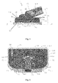
Figure 1 shows a schematic side view of a portion of a floor cleaning apparatus according to an embodiment of the present invention, with a handle of the apparatus at an operative position relative to a floor cleaning head of the apparatus, and with stabilisers of the apparatus at respective stowed positions relative to the floor cleaning head; -
Figure 2 shows a schematic top view of the portion of the apparatus in the state shown inFigure 1 but with a hood of the floor cleaning head not shown so that interior components of the floor cleaning head are visible; -
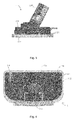
Figure 3 shows a schematic side view of the portion of the apparatus, with the handle having been rotated relative to the floor cleaning head from the position shown inFigure 1 towards a stored position, and with the stabilisers at the respective stowed positions; -
Figure 4 shows a schematic top view of the portion of the apparatus in the state shown inFigure 3 with the hood of the floor cleaning head not shown so that the interior components of the floor cleaning head are visible; -
Figure 5 shows a schematic side view of the portion of the apparatus, with the handle having been further rotated relative to the floor cleaning head from the position shown inFigure 3 towards the stored position, and with the stabilisers having been moved relative to the floor cleaning head from the positions shown inFigure 3 towards respective deployed positions; -
Figure 6 shows a schematic top view of the portion of the apparatus in the state shown inFigure 5 with the hood of the floor cleaning head not shown so that the interior components of the floor cleaning head are visible; -
Figure 7 shows a schematic side view of the portion of the apparatus, with the handle having been further rotated relative to the floor cleaning head from the position shown inFigure 5 towards the stored position, and with the stabilisers having been further moved relative to the floor cleaning head from the positions shown inFigure 5 towards the respective deployed positions; -
Figure 8 shows a schematic top view of the portion of the apparatus in the state shown inFigure 7 with the hood of the floor cleaning head not shown so that the interior components of the floor cleaning head are visible; -
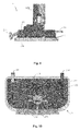
Figure 9 shows a schematic side view of the portion of the apparatus, with the handle having been further rotated relative to the floor cleaning head from the position shown inFigure 7 so as to be at the stored position, and with the stabilisers having been further moved relative to the floor cleaning head from the positions shown inFigure 7 so as to be at the respective deployed positions; -
Figure 10 shows a schematic top view of the portion of the apparatus in the state shown inFigure 9 with the hood of the floor cleaning head not shown so that the interior components of the floor cleaning head are visible; -
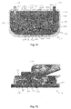
Figure 11 shows a schematic top view of the portion of the apparatus in the state shown inFigure 10 with the hood of the floor cleaning head, the handle and a foot pedal of the apparatus not shown so that the interior components of the floor cleaning head are visible; -
Figure 12 shows a schematic cross-sectional view of the portion of the apparatus in the state shown inFigure 1 ; -
Figure 13 shows a schematic cross-sectional view of the portion of the apparatus in the state shown inFigure 7 ; and -
Figure 14 shows a schematic cross-sectional view of the portion of the apparatus in the state shown inFigure 9 . - Referring to
Figures 1 and 2 , there is shown a schematic side view and a schematic top view of a portion of a floor cleaning apparatus 1 according to an embodiment of the present invention. In this embodiment, the apparatus 1 is a steam mop, but in other embodiments the apparatus 1 may be other than a steam mop. Herein, the steam mop of this embodiment will be referred to simply as the apparatus 1. - The apparatus 1 comprises a
floor cleaning head 100, which has atop 111, abottom 121, and a plurality ofsides top 111 and thebottom 121. Afloor cleaning pad 120 is coupled to the bottom 121. A clamp 110 is coupled to the top 111 of thefloor cleaning head 100 by screw fastening or other fastening means. For ease of reference only, the plurality ofsides front side 130, arear side 140, aleft side 150, and aright side 160, respectively, of thefloor cleaning head 100. Thefloor cleaning head 100 has a length measured between and orthogonal to the front andrear sides right sides bottom 121 of thefloor cleaning head 100 is orientated to face the floor, so that the top 111 andsides floor cleaning head 100 are above the bottom 121, and the bottom 121 is located between the floor and the top 111 andsides floor cleaning head 100. In this embodiment, thefloor cleaning head 100 comprises a hood 102 that defines the top 111, the bottom 121 and thesides floor cleaning head 100. In some embodiments, the hood 102 is detachable from thefloor cleaning pad 120 for servicing the apparatus 1. In other embodiments, the hood 102 andfloor cleaning pad 120 is permanently fixed to each other, or are respective portions of a single unitary component. InFigures 2 ,4 ,6 ,8 ,10 and11 , the hood 102 is not shown, in order to make visible interior components of thefloor cleaning head 100. - In this embodiment, as best seen in
Figure 11 , ahole 123 is formed in the cleaning head to receive a steam conduit (not shown). The steam conduit such as a tube is in fluid communication with a steam diffuser (not shown) which is located adjacent to thefloor cleaning pad 120. The steam diffuser is known to a person skilled in the art and for the purposes for brevity will not be discussed any further. - Turning back to
Figure 2 , a plurality of screw holes 122 extend through the bottom 121 between the interior and exterior of thefloor cleaning head 100. The screw holes 122 are configured to retaining screws for coupling thefloor cleaning pad 120 to the bottom 121. The coupling of thefloor cleaning pad 120 to the bottom 121 will be discussed in further detail below. The apparatus 1 is for arranged to direct steam through the steam conduit and steam diffuser from the interior to the exterior of thefloor cleaning head 100, so as to emit the steam at the bottom 121 of thefloor cleaning head 100, when the apparatus 1 is being used to clean a floor. Such steam may help to free-up dirt from the floor being cleaned, and may help to disinfect the floor. In this embodiment, the apparatus 1 has a reservoir (not shown) for holding a volume of water, and a heater (not shown) for heating the water sufficiently to generate the steam. In this embodiment, the heater is electrically-powered so that passing an electric current through the heater causes the heater to heat up, and the apparatus 1 has an electrical cable (not shown) for connecting the heater to the mains electrical power supply. Alternatively the floor cleaning apparatus 1 is battery powered and the apparatus comprises a rechargeable battery pack. In other embodiments, the apparatus 1 may be for emitting steam at the bottom 121 of thefloor cleaning head 100 in some other manner. In this embodiment, the bottom 121 comprises a plurality of connectors (not shown) which are mounted on at screw holes 122 for connecting afloor cleaning pad 120, such as a microfibre pad, to thebottom 121 of thefloor cleaning head 100. When such a pad is connected to the bottom 121 and the apparatus 1 is being used to clean a floor, steam emitted moistens the pad, to facilitate removal of dirt from the floor. In this embodiment, the connectors are hook or loop portions of a hook-and-loop fastener (e.g. Velcro ™) fastened to the hood 102 by a screw fastener, but in other embodiments the connectors may take a different form or be omitted. Thefloor cleaning pad 120 may comprises a reciprocal hook and loop fastening portion or alternative fastening means. Thefloor cleaning pad 120 may comprise different a plurality of different fibres and may comprise one ormore portions 124 with longer fibre lengths or different material. In some embodiments, the bottom 121 comprises only one connector for connecting afloor cleaning pad 120, such as a microfibre pad, to thebottom 121 of thefloor cleaning head 100. In some embodiments, the apparatus 1 comprises a floor cleaning pad for releasable attachment to thebottom 121 of thefloor cleaning head 100. - When the apparatus 1 is being used to clean a floor, the
bottom 121 of thefloor cleaning head 100 is substantially parallel to the floor. In some embodiments, the bottom 121 may be planar, or flat. In other embodiments, the bottom 121 may be non-planar. For example, in this embodiment the bottom 121 is planar, at least because thefloor cleaning pad 120 is substantially planar and compressible and the bottom 121 is planar in a plane P-P. - The apparatus 1 also has a
handle interface 200 for coupling a handle or floor cleaning apparatus body (not shown). Thehandle interface 200 comprises a slot for receiving the handle and a latch or fastening means secures the handle to thehandle interface 200. A longitudinal axis of the handle may be coaxial with the longitudinal axis L-L of thehandle interface 200. Alternatively the longitudinal axis of the handle may be parallel or substantially parallel to the longitudinal axis L-L of thehandle interface 200. In some embodiments, thehandle interface 200 is optional and the handle couples directly to the universal joint. Thehandle interface 200 is connected to thefloor cleaning head 100, in this embodiment via a universal joint (now shown) at an end of thehandle interface 200. The universal joint is coupled to the floor cleaning head via clamp 110. The clamp 110 comprises circular recesses for receivingpegs 125 of the universal joint for rotation about the first axis A1-A1. In this embodiment, thehandle interface 200 and the handle are elongate, although only thehandle interface 200 is shown in the Figures, and has a longitudinal axis L-L, as indicated inFigure 1 . Thehandle interface 200 is movable relative to thefloor cleaning head 100 between an operative position, as shown inFigures 1, 2 and12 , and a stored position, as shown inFigures 9, 10 and14 . When thehandle interface 200 is at the operative position, thehandle interface 200 is inclined relative to thefloor cleaning head 100, so that the longitudinal axis L-L forms an acute angle α with the plane P-P and the bottom 121. Accordingly, when thehandle interface 200 is at the operative position, a user is able to manoeuvre the apparatus 1 comfortably. The universal joint of thehandle interface 200 enables rotation of thehandle interface 200 relative to thefloor cleaning head 100 about two orthogonal axes A1-A1, A2-A2. As shown inFigures 1 to 3 , a first axis A1-A1 of the axes is parallel to the width of thefloor cleaning head 100 for permitting up-and-down rotational movement of thehandle interface 200 relative to thefloor cleaning head 100 to vary the angle α between the longitudinal axis L-L and the plane P-P. As shown inFigure 1 , a second axis A2-A2 of the axes is orthogonal to the first axis A1-A1 for permitting side-to-side rotational movement of thehandle interface 200 relative to thefloor cleaning head 100. In other embodiments, thehandle interface 200 may be movably connected to thefloor cleaning head 100 by a connection other than a universal joint. - When the
handle interface 200 is at the stored position, the longitudinal axis L-L of thehandle interface 200 is closer to ninety degrees to the plane P-P and thebottom 121 of thefloor cleaning head 100 than when thehandle interface 200 is at the operative position. Accordingly, when thehandle interface 200 is at the stored position, thehandle interface 200 is more upright than when thehandle interface 200 is at the operative position, so that the apparatus 1 requires less horizontal space for storage. In this embodiment, the apparatus 1 has a lock (not shown) for fixing thehandle interface 200 in position relative to thefloor cleaning head 100 when thehandle interface 200 is at the stored position. This helps prevent thehandle interface 200 from falling, if thehandle interface 200 is knocked inadvertently by a passer-by during storage of the apparatus 1. - In this embodiment, when the
handle interface 200 is at the stored position, the apparatus may be left to stand in a self-supporting manner with thebottom 121 of thefloor cleaning head 100 still facing a floor. However, even though the apparatus 1 is more stable when in this state than when thehandle interface 200 is at the operative position, the apparatus 1 still may be knocked inadvertently by a passer-by. In order to help increase the stability of the apparatus 1, the apparatus 1 of this embodiment has first andsecond stabilisers stabilisers floor cleaning head 100. Thestabilisers floor cleaning head 100 for movement relative to thefloor cleaning head 100 from a stowed position, as shown inFigures 1 to 4 and12 , to a deployed position, as shown inFigures 9 to 11 and14 , for increasing stability of the apparatus 1. - In this embodiment, each of the
stabilisers floor cleaning head 100 from the stowed position to the deployed position at thefront side 130 of thefloor cleaning head 100. Therefore, the shape and structure of the bottom 121 of thefloor cleaning head 100 need not be dependent on the shape and position of thestabilisers mechanism 400, described below, for controlling their movement. Accordingly, the shape of the bottom 121 is able to be made most suitable for floor cleaning and for retaining thefloor cleaning pad 120. - In this embodiment, movement of the
stabilisers floor cleaning head 100 from the respective stowed positions to the respective deployed positions comprises movement of thestabiliser front side 130 of thefloor cleaning head 100. Therefore, if a combination of thestabilisers floor cleaning head 100 is considered to be a body, and the body has a length in a direction parallel to the length of thefloor cleaning head 100, such movement of thestabilisers stabilisers floor cleaning head 100 from the respective stowed positions to the respective deployed positions may be in a direction parallel to thefront side 130 of thefloor cleaning head 100, and may not increase the length of the body. - In this embodiment, movement of the
stabilisers floor cleaning head 100 from the respective stowed positions to the respective deployed positions comprises movement of thestabilisers front side 130 of thefloor cleaning head 100. More specifically, in this embodiment, when thestabilisers stabilisers floor cleaning head 100. Therefore, thestabilisers stabilisers stabilisers front side 130 of thefloor cleaning head 100 from the interior of thefloor cleaning head 100 to the exterior of thefloor cleaning head 100. In other embodiments, movement of thestabilisers floor cleaning head 100 from the respective stowed positions to the respective deployed positions comprises movement of thestabilisers floor cleaning head 100, and thestabilisers side floor cleaning head 100. - In this embodiment, the
stabilisers floor cleaning head 100 between the stowed position and the deployed position without protruding from thebottom 121 of thefloor cleaning head 100. Therefore, movement of thestabilisers floor cleaning head 100 need not cause the apparatus 1 to be lifted from the floor, when the apparatus 1 is standing with the bottom 121 facing the floor, which otherwise could unbalance the apparatus 1 and cause it to topple. Moreover, this avoids the risk of deployment of thestabilisers floor cleaning pad 120 connected to the bottom 121, in instances when a floor cleaning pad is so connected to the bottom 121. Movement of thestabilisers floor cleaning pad 120 and thefloor cleaning pad 120 is not required to have holes therein to receive thestabilisers floor cleaning pad 120 can at least cover the entire surface of the bottom 121 and in some embodiments thefloor cleaning pad 120 can have an area greater than the area of the bottom 121. - In this embodiment, movement of the
stabilisers stabilisers stabilisers stabilisers front side 130 of thefloor cleaning head 100 closer to the floor when standing with the bottom 121 facing a substantially flat floor, thestabilisers - In some embodiments, when the
stabilisers stabiliser stabilisers - In particular the
stabilisers Figure 7 withFigure 9 . Thestabilisers floor cleaning pad 120 below thebottom 121. If the stabilisers 310,320 only extended to a position in line with the bottom 121, the floor cleaning pad is compressible and can cause tilting of floor cleaning apparatus 1 if the compression of thefloor cleaning pad 120 is not uniform (e.g. on one side only). This means that the stabilisers prevent thefloor cleaning pad 120 from compressing under the weight of the floor cleaning apparatus 1. In this way thefloor cleaning pad 120 cannot compress only on one side which can exaggerate the tilting of the floor cleaning apparatus 1. - In this embodiment, the centre of mass of the apparatus 1 is located so that the apparatus 1 is stable when the following three conditions are met simultaneously: (a) the
handle interface 200 is at the stored position, and (b) thestabilisers stabilisers bottom 121 of thefloor cleaning head 100 is standing on a surface inclined at fifteen degrees to the horizontal. - This means that, were the apparatus 1 to be knocked when conditions (a) and (b) are true, after removal of the knocking force, the apparatus 1 would not topple but would instead return, relative to the floor, to the position it had before receiving the knock. In some embodiments the centre of mass is modified such that the floor cleaning apparatus 1 does not topple if it receives a knock when all three conditions (a) (b) and (c) are met. In some variations to this embodiment, the centre of mass of the apparatus 1 is located so that the apparatus 1 is stable when the first two conditions are true and the third condition is that the
bottom 121 of thefloor cleaning head 100 is standing on a surface inclined at more than fifteen degrees to the horizontal, such as twenty degrees to the horizontal or twenty-five degrees to the horizontal. - In this embodiment, movement of the
handle interface 200 relative to thefloor cleaning head 100 from the operative position to the stored position causes thestabilisers floor cleaning head 100 from their respective stowed positions to their respective deployed position. More specifically, in this embodiment, the apparatus 1 has amechanism 400 that is for converting movement of thehandle interface 200 relative to thefloor cleaning head 100 from the operative position to the stored position into movement of thestabilisers floor cleaning head 100 from their respective stowed positions to their respective deployed position. Themechanism 400 of this embodiment will now be described in more detail with reference toFigure 11 . - In this embodiment, the
mechanism 400 comprises afirst member 410, asecond member 420, aresilient apparatus 430, afirst arm 440, asecond arm 450, and atorsion spring 460. Thefirst member 410 is slidably connected to thesecond member 420 via theresilient apparatus 430 for movement in a direction parallel to the length of thefloor cleaning head 100. Afront face 411 of thefirst member 410 is for abutting a lower end of thehandle interface 200 on sufficient rotation of thehandle interface 200 relative to thefloor cleaning head 100 from the operative position, as will be described below. Thesecond member 420 is slidably connected to thefloor cleaning head 100, and more specifically to the chassis 101, for movement in a direction parallel to the length of thefloor cleaning head 100. Respective first ends 441, 451 of the first andsecond arms second frame 420, and respective second ends 442, 452 of the first andsecond arms second stabilisers second arms floor cleaning head 100, and more specifically to the chassis 101, atrespective pivots 445, 455. The pivots are between the first and second ends 441, 442, 451, 452 of the first andsecond arms torsion spring 460 has a first end fixed to thefirst arm 440 and a second end fixed to thefloor cleaning head 100. Thetorsion spring 460 is arranged to bias thefirst arm 440 to rotate in an anticlockwise direction, asFigure 11 is drawn. Accordingly, thetorsion spring 460 biases thefirst member 410 away from therear side 140 of thefloor cleaning head 100, and thus biases thestabilisers second arms second arms second arms - The
resilient apparatus 430 is arranged to bias the first andsecond members resilient apparatus 430 comprises twocoil springs first member 410, and respective second ends of the coil springs 431, 432 are fixed to thesecond member 420. In this embodiment, the coil springs 431, 432 are compression coil springs, which are arranged to bias the first andsecond members second members resilient apparatus 430 may take a different form or be omitted. For example, in some embodiments, thefirst member 410 may be immovable relative to, and optionally unitary with, thesecond frame 420. - Referring again to
Figure 11 , thestabilisers respective channels floor cleaning head 100. Thechannels stabilisers floor cleaning head 100 between their stowed and deployed positions. Referring toFigure 12 , thefirst stabiliser 310 has first andsecond followers floor cleaning head 100. Similarly, although not shown in the Figures, thesecond stabiliser 320 has first and second followers, which are respectively located in third and fourth cam tracks of thefloor cleaning head 100. Each of the first to fourth cam tracks 181, 182 has a front-most end closest to thefront side 130 of thefloor cleaning head 100, and a rear-most end closest to therear side 140 of thefloor cleaning head 100. The first and third cam tracks 181 are linear and parallel to the plane P-P, whereas each of the second and fourth cam tracks 182 has first and secondlinear portions 182a, 182c parallel to the plane P-P that are joined by a mid-portion 182b that is inclined to the plane P-P. Thefollowers stabilisers floor cleaning head 100, so as to rotate thestabilisers floor cleaning head 100 as thestabilisers - Movement of the
handle interface 200 relative to thefloor cleaning head 100 to cause movement of thestabilisers floor cleaning head 100 in accordance with this embodiment will now be described in more detail with reference to the Figures. -
Figures 1, 2 and12 show thehandle interface 200 at its operative position relative to thefloor cleaning head 100, and thestabilisers followers second stabilisers floor cleaning head 100. As described above, thehandle interface 200 is rotatable relative to thefloor cleaning head 100 about the first axis A1-A1 to vary the angle α between the longitudinal axis L-L and the plane P-P. As will be appreciated through comparison ofFigures 1 and 2 withFigures 3 and 4 , thehandle interface 200 is movable to a certain extent in this manner without causing movement of thestabilisers floor cleaning head 100. - As the
handle interface 200 is further rotated relative to thefloor cleaning head 100 about the first axis A1-A1 from the position shown inFigures 3 and 4 towards the stored position, the lower end of thehandle interface 200 abuts thefront face 411 of thefirst member 410. Continued such movement of thehandle interface 200 urges thefirst member 410 to slide towards therear side 140 of thefloor cleaning head 100. Theresilient apparatus 430 has a spring constant suitable to transmit this rearward movement of thefirst member 410 to thesecond member 420 without deforming theresilient apparatus 430, so that thesecond member 420 also is urged towards therear side 140 of thefloor cleaning head 100. By comparingFigures 4 and6 , it can be seen that such movement of thesecond member 420 relative to thefloor cleaning head 100 causes the first andsecond arms respective pivots 445, 455, and against the bias of thetorsion spring 460. In turn, such movement of the first andsecond arms floor cleaning head 100 causes the first andsecond stabilisers floor cleaning head 100 from their respective stowed positions, shown inFigures 3 and 4 , towards their respective deployed positions. During such movement of thestabilisers second followers stabilisers floor cleaning head 100 along respectivelinear portions 182a of the first to fourth cam tracks 181, 182. Therefore, thestabilisers Figure 4 to the position shown inFigure 6 in a direction substantially parallel to the plane P-P. - As the
handle interface 200 is still further rotated relative to thefloor cleaning head 100 about the first axis A1-A1 from the position shown inFigures 5 and 6 towards the stored position, thehandle interface 200 continues to cause the first andsecond members rear side 140 of thefloor cleaning head 100. This causes the first andsecond arms respective pivots 445, 455, and the first andsecond stabilisers floor cleaning head 100 from their positions shown inFigures 5 and 6 to their positions shown inFigures 7, 8 and13 . During such continued movement of thestabilisers first followers 311 of thestabilisers second followers 312 of thestabilisers stabilisers Figures 5 and 6 to the position shown inFigures 7 and 8 , so that distal ends of therespective stabilisers - As the
handle interface 200 is yet further rotated relative to thefloor cleaning head 100 about the first axis A1-A1 from the position shown inFigures 7, 8 and13 until it arrives at the stored position, thehandle interface 200 continues to cause the first andsecond members rear side 140 of thefloor cleaning head 100. This causes the first andsecond arms respective pivots 445, 455, and the first andsecond stabilisers floor cleaning head 100 from their positions shown inFigures 7, 8 and13 to their deployed positions shown inFigures 9 to 11 and14 . During such continued movement of thestabilisers first followers 311 of thestabilisers second followers 312 of thestabilisers stabilisers Figures 9 to 11 and14 , thesecond followers 312 would not pass back down the inclined mid-portions 182b of the second and fourth cam tracks 182 if a turning moment is applied to thestabilisers second followers 312 towards the plane P-P, since the second linear portions 182c of the second and fourth cam tracks 182 are parallel to the plane P-P. When thehandle interface 200 reaches the stored position, the lock (not shown) fixes thehandle interface 200 in position relative to thefloor cleaning head 100. - This means that the at least one
stabiliser bottom 121 of the floor cleaning head a distance of substantially the thickness of thefloor cleaning pad 120. In this way thefloor cleaning pad 120 is still in contact with the floor in the stowed position, but thestabilisers floor cleaning pad 120 from compressing. This means that thefloor pad 120 itself can partially support the weight of the floor cleaning apparatus 1 without compressing in a nonuniform manner. Furthermore by having thefloor cleaning pad 120 in contact with the floor, thepad 120 itself increases the coefficient of friction between floor and the floor cleaning apparatus 1 and this prevents the floor cleaning apparatus 1 from sliding, particularly on an incline. - In some embodiments, the
stabilisers pad 120. In this case thefloor cleaning pad 120 is not in contact with the floor when in the stowed position. This can be useful to prevent a dirty floor cleaning pad touching a clean floor when the floor cleaning apparatus is in the stowed position. - In order to move the
stabilisers handle interface 200 is moved from its stored position, shown inFigures 9 to 11 and14 , towards its operative position, shown inFigures 1, 2 and12 . In this embodiment, unlocking of the lock is effected through user actuation of afoot pedal 190 at therear side 140 of thefloor cleaning head 100. The manner in which actuation of thefoot pedal 190 causes unlocking of the lock will not be described in the interests of conciseness, but a suitable mechanism would be known to the person skilled in the art in light of this disclosure. During this movement of thehandle interface 200 towards its operative position, the lower end of thehandle interface 200 moves in a direction away from therear side 140 of thefloor cleaning head 100 and away from thefront face 411 of thefirst member 410. However, thetorsion spring 460 acts to rotate thefirst arm 440 in an anticlockwise direction, asFigure 11 is drawn, and thus to bias thefirst member 410 away from therear side 140 of thefloor cleaning head 100, so as to bias thestabilisers handle interface 200 from its stored position to its operative position causes thestabilisers floor cleaning head 100 from their respective deployed positions to their respective stowed positions. - In some cases, a user may choose to move the
handle interface 200 relative to thefloor cleaning head 100 from its operative position towards its stored position when movement to the deployed position of one or both of thestabilisers front side 130 of thefloor cleaning head 100 abutting a wall. When movement of thestabilisers handle interface 200 of this embodiment is movable relative to thefloor cleaning head 100 from the operative position to the stored position without causing thestabilisers floor cleaning head 100 to the respective deployed positions. More specifically, movement of thehandle interface 200 relative to thefloor cleaning head 100 towards the stored position causes thestabilisers handle interface 200 relative to thefloor cleaning head 100 towards the stored position by application of a force sufficient to overcome the biasing force of theresilient apparatus 430 causes relative movement of the first andsecond members coil springs resilient apparatus 430. In embodiments in which theresilient apparatus 430 takes a different form to that of this embodiment, deformation of theresilient apparatus 430 may be effected in some other manner. The first andsecond members handle interface 200 from its operative position to its stored position without moving thestabilisers stabilisers mechanism 400 in the scenario described above, in which movement of thestabilisers - In a similar manner, this deformability of the
resilient apparatus 430 permits thestabilisers floor cleaning head 100 from their respective deployed positions to their respective stowed positions without causing movement of thehandle interface 200 relative to thefloor cleaning head 100 from its stored position. Accordingly, when the apparatus 1 is arranged with thehandle interface 200 at its stored position and thestabilisers stabilisers stabilisers resilient apparatus 430, the first andsecond members resilient apparatus 430. Again, this helps to avoid damage to thestabilisers mechanism 400. - The
resilient apparatus 430 thus may be considered an apparatus for controlled deformation, that is arranged to absorb energy from forces sufficient to overcome the biasing force of theresilient apparatus 430 and applied to thestabilisers handle interface 200 when movement of the other is obstructed or prevented, to help avoid such forces damaging thestabilisers mechanism 400. - This embodiment of the present invention therefore provides a mechanism for helping to reduce the risk of toppling of the apparatus 1 when the apparatus 1 is not in use. The mechanism is unobtrusive when the apparatus 1 is in use.
- The above embodiments are to be understood as illustrative examples of the invention. Further embodiments of the invention are envisaged. For example, in some embodiments, stabilisers, such as spaced apart stabilisers, may be movable relative to the
floor cleaning head 100 from the stowed position to the deployed position at the rear, or left, orright side floor cleaning head 100 for increasing stability of the apparatus 1, instead of, or in addition to, at thefront side 130 of thefloor cleaning head 100. For example, at least one additional rear stabiliser may be provided on thefloor cleaning head 100. The at least one additional rear stabiliser may be actuated and project rearwardly, in an opposite direction to the first andsecond stabilisers handle interface 200 and the at least one rear stabiliser. The at leat one rear stabiliser may be configured to move in a rearward direction when thehandle interface 200 is moved into a deployed position. This would mean that the stabilisers move forwards and backwards when the floor cleaning apparatus 1 is put in the stowed position. In some embodiments, the apparatus 1 may have only one stabiliser. The stabiliser may be movable relative to thefloor cleaning head 100 from the stowed position to the deployed position at the front, or rear, or left, orright side floor cleaning head 100. It is to be understood that any feature described in relation to any one embodiment may be used alone, or in combination with other features described, and may also be used in combination with one or more features of any other of the embodiments, or any combination of any other of the embodiments. Furthermore, equivalents and modifications not described above may also be employed without departing from the scope of the invention, which is defined in the accompanying claims.
Claims (15)
- A floor cleaning apparatus, comprising:a floor cleaning head having a top, a bottom, and a side extending between the top and the bottom, wherein the bottom is for facing a floor during cleaning of the floor;a floor cleaning pad coupled to the bottom of the floor cleaning head; andat least one stabiliser, wherein the, or each, stabiliser is connected to the floor cleaning head and is movable relative to the floor cleaning head from a stowed position to a deployed position at the side of the floor cleaning head for increasing stability of the apparatus.
- A floor cleaning apparatus according to claim 1, wherein movement of the, or each, stabiliser relative to the floor cleaning head from the stowed position to the deployed position comprises movement of the, or each, stabiliser from the side of the floor cleaning head.
- A floor cleaning apparatus according to claim 1 or claim 2, wherein movement of the, or each, stabiliser relative to the floor cleaning head from the stowed position to the deployed position comprises movement of the, or each, stabiliser through the side of the floor cleaning head.
- A floor cleaning apparatus according to any one of the preceding claims, wherein the bottom of the floor cleaning head has a surface with one or more parts that lie in a plane, and wherein movement of the, or each, stabiliser relative to the floor cleaning head from the stowed position to the deployed position comprises movement of the, or each, stabiliser towards the plane.
- A floor cleaning apparatus according to any one of the preceding claims, wherein the, or each, stabiliser is moveable relative to the floor cleaning head between the stowed position and the deployed position without protruding from the bottom of the floor cleaning head.
- A floor cleaning apparatus according to any one of the preceding claims, comprising a handle connected to the floor cleaning head, wherein the handle is movable relative to the floor cleaning head from an operative position to a stored position to cause the, or each, stabiliser to move relative to the floor cleaning head from the stowed position to the deployed position.
- A floor cleaning apparatus according to claim 6, wherein the handle is movable relative to the floor cleaning head from the operative position to the stored position without causing the, or each, stabiliser to move relative to the floor cleaning head to the deployed position, when movement of the, or each, stabiliser relative to the floor cleaning head to the deployed position is obstructed.
- A floor cleaning apparatus according to claim 6 or claim 7, wherein the, or each, stabiliser is moveable relative to the floor cleaning head from the deployed position towards the stowed position without causing movement of the handle relative to the floor cleaning head from the stored position.
- A floor cleaning apparatus according to any one of claims 6 to 8, comprising a mechanism for converting movement of the handle relative to the floor cleaning head from the operative position to the stored position into movement of the, or each, stabiliser relative to the floor cleaning head from the stowed position to the deployed position; and
wherein the mechanism comprises first and second members that are moveable relative to each other so as to absorb movement of the handle from the operative position to the stored position without moving the, or each, stabiliser from the stowed position to the deployed position. - A floor cleaning apparatus according to claim 9, wherein the mechanism comprises a resilient apparatus that is arranged to bias the first and second members apart.
- A floor cleaning apparatus according to any one of claims 6 to 10, comprising a lock for fixing the handle in position relative to the floor cleaning head when the handle is at the stored position.
- A floor cleaning apparatus according to any one of 6 to 11, wherein the handle has a longitudinal axis, and wherein the longitudinal axis is closer to ninety degrees to the bottom of the floor cleaning head when the handle is at the stored position than when the handle is at the operative position.
- A floor cleaning apparatus according to any one of claims 6 to 12, wherein the floor cleaning apparatus has a centre of mass that is located so that the floor cleaning apparatus is stable when the handle is at the stored position, the, or each, stabiliser is at the deployed position, and the bottom of the floor cleaning head is standing on a surface inclined at fifteen degrees to the horizontal.
- A floor cleaning apparatus according to any one of the preceding claims, wherein the bottom of the floor cleaning head includes one or more connectors for connecting a floor cleaning pad to the bottom of the floor cleaning head.
- A floor cleaning apparatus according to any one of the preceding claims, wherein the at least one stabiliser extends below the bottom of the floor cleaning head a distance of substantially the thickness of the floor cleaning pad.
Priority Applications (1)
| Application Number | Priority Date | Filing Date | Title |
|---|---|---|---|
| EP15154518.3A EP3056128B1 (en) | 2015-02-10 | 2015-02-10 | Floor cleaning apparatus |
Applications Claiming Priority (1)
| Application Number | Priority Date | Filing Date | Title |
|---|---|---|---|
| EP15154518.3A EP3056128B1 (en) | 2015-02-10 | 2015-02-10 | Floor cleaning apparatus |
Publications (2)
| Publication Number | Publication Date |
|---|---|
| EP3056128A1 true EP3056128A1 (en) | 2016-08-17 |
| EP3056128B1 EP3056128B1 (en) | 2020-01-08 |
Family
ID=52462852
Family Applications (1)
| Application Number | Title | Priority Date | Filing Date |
|---|---|---|---|
| EP15154518.3A Active EP3056128B1 (en) | 2015-02-10 | 2015-02-10 | Floor cleaning apparatus |
Country Status (1)
| Country | Link |
|---|---|
| EP (1) | EP3056128B1 (en) |
Cited By (1)
| Publication number | Priority date | Publication date | Assignee | Title |
|---|---|---|---|---|
| GB2632611A (en) * | 2022-09-14 | 2025-02-12 | Numatic Int Ltd | Floor Treatment Machine |
Citations (3)
| Publication number | Priority date | Publication date | Assignee | Title |
|---|---|---|---|---|
| US20040134025A1 (en) * | 2003-01-10 | 2004-07-15 | Royal Appliance Mfg. Co. | Vacuum cleaner with cleaning pad |
| DE102011001631A1 (en) | 2010-03-30 | 2011-10-06 | Vorwerk & Co. Interholding Gmbh | Damp cleaning device, particularly ground wiping devices for damp cleaning of hard floor mats, e.g. tile grounds or parquet floor, has guiding part and damp element, which has cloth |
| WO2013139364A1 (en) * | 2012-03-19 | 2013-09-26 | Aktiebolaget Electrolux | Upright vacuum cleaner having a support |
Family Cites Families (1)
| Publication number | Priority date | Publication date | Assignee | Title |
|---|---|---|---|---|
| AU2013201282B2 (en) * | 2012-03-09 | 2014-06-19 | Bissell Inc. | Surface cleaning apparatus |
-
2015
- 2015-02-10 EP EP15154518.3A patent/EP3056128B1/en active Active
Patent Citations (3)
| Publication number | Priority date | Publication date | Assignee | Title |
|---|---|---|---|---|
| US20040134025A1 (en) * | 2003-01-10 | 2004-07-15 | Royal Appliance Mfg. Co. | Vacuum cleaner with cleaning pad |
| DE102011001631A1 (en) | 2010-03-30 | 2011-10-06 | Vorwerk & Co. Interholding Gmbh | Damp cleaning device, particularly ground wiping devices for damp cleaning of hard floor mats, e.g. tile grounds or parquet floor, has guiding part and damp element, which has cloth |
| WO2013139364A1 (en) * | 2012-03-19 | 2013-09-26 | Aktiebolaget Electrolux | Upright vacuum cleaner having a support |
Cited By (1)
| Publication number | Priority date | Publication date | Assignee | Title |
|---|---|---|---|---|
| GB2632611A (en) * | 2022-09-14 | 2025-02-12 | Numatic Int Ltd | Floor Treatment Machine |
Also Published As
| Publication number | Publication date |
|---|---|
| EP3056128B1 (en) | 2020-01-08 |
Similar Documents
| Publication | Publication Date | Title |
|---|---|---|
| CN113873928B (en) | Device for cleaning walkable surfaces | |
| EP2494904B1 (en) | Surface cleaning apparatus with pivoting manifold | |
| CN102510729B (en) | Walking stick | |
| US9743819B2 (en) | Floor mop with concentrated cleaning feature | |
| US8667643B2 (en) | Method and apparatus for assisting pivot motion of a handle in a floor treatment device | |
| CN101161174B (en) | Nozzle assembly with auxiliary brush unit | |
| KR101491002B1 (en) | vacuum cleaner | |
| KR20210057810A (en) | Cleaning head for a surface treatment device having one or more stabilizers and a surface treatment device having the same | |
| US8584300B2 (en) | Squeeze mop | |
| EP3056127B1 (en) | Floor cleaning apparatus | |
| CN119012952A (en) | Floor treatment device comprising a guide member with an engagement assembly | |
| US9681789B2 (en) | Floor mop with scrubber | |
| CA2703657C (en) | Squeeze mop | |
| AU2009202139B2 (en) | Upright type cleaner | |
| EP3056128B1 (en) | Floor cleaning apparatus | |
| TW201249387A (en) | Cleaning member mounting holder for mop and mop | |
| CN102711578B (en) | Combined mop head and wringer | |
| US20150082565A1 (en) | Sliding scrub brush for a floor mop | |
| AU2013288828B2 (en) | Cleaning device having a variable size and shape head | |
| US20070136963A1 (en) | Butterfly mops with automated scrubber | |
| KR100816872B1 (en) | Multi cleaner | |
| US8006341B2 (en) | Floor-cleaning appliance | |
| EP4378367A1 (en) | Cleaner | |
| CN215656965U (en) | Folding handle and cleaning machine | |
| JP3940420B2 (en) | Electric vacuum cleaner |
Legal Events
| Date | Code | Title | Description |
|---|---|---|---|
| PUAI | Public reference made under article 153(3) epc to a published international application that has entered the european phase |
Free format text: ORIGINAL CODE: 0009012 |
|
| AK | Designated contracting states |
Kind code of ref document: A1 Designated state(s): AL AT BE BG CH CY CZ DE DK EE ES FI FR GB GR HR HU IE IS IT LI LT LU LV MC MK MT NL NO PL PT RO RS SE SI SK SM TR |
|
| AX | Request for extension of the european patent |
Extension state: BA ME |
|
| STAA | Information on the status of an ep patent application or granted ep patent |
Free format text: STATUS: REQUEST FOR EXAMINATION WAS MADE |
|
| 17P | Request for examination filed |
Effective date: 20170209 |
|
| RBV | Designated contracting states (corrected) |
Designated state(s): AL AT BE BG CH CY CZ DE DK EE ES FI FR GB GR HR HU IE IS IT LI LT LU LV MC MK MT NL NO PL PT RO RS SE SI SK SM TR |
|
| STAA | Information on the status of an ep patent application or granted ep patent |
Free format text: STATUS: EXAMINATION IS IN PROGRESS |
|
| 17Q | First examination report despatched |
Effective date: 20181105 |
|
| GRAP | Despatch of communication of intention to grant a patent |
Free format text: ORIGINAL CODE: EPIDOSNIGR1 |
|
| STAA | Information on the status of an ep patent application or granted ep patent |
Free format text: STATUS: GRANT OF PATENT IS INTENDED |
|
| GRAJ | Information related to disapproval of communication of intention to grant by the applicant or resumption of examination proceedings by the epo deleted |
Free format text: ORIGINAL CODE: EPIDOSDIGR1 |
|
| GRAP | Despatch of communication of intention to grant a patent |
Free format text: ORIGINAL CODE: EPIDOSNIGR1 |
|
| INTG | Intention to grant announced |
Effective date: 20190912 |
|
| INTG | Intention to grant announced |
Effective date: 20190925 |
|
| GRAS | Grant fee paid |
Free format text: ORIGINAL CODE: EPIDOSNIGR3 |
|
| GRAA | (expected) grant |
Free format text: ORIGINAL CODE: 0009210 |
|
| STAA | Information on the status of an ep patent application or granted ep patent |
Free format text: STATUS: THE PATENT HAS BEEN GRANTED |
|
| AK | Designated contracting states |
Kind code of ref document: B1 Designated state(s): AL AT BE BG CH CY CZ DE DK EE ES FI FR GB GR HR HU IE IS IT LI LT LU LV MC MK MT NL NO PL PT RO RS SE SI SK SM TR |
|
| REG | Reference to a national code |
Ref country code: GB Ref legal event code: FG4D |
|
| REG | Reference to a national code |
Ref country code: CH Ref legal event code: EP |
|
| REG | Reference to a national code |
Ref country code: IE Ref legal event code: FG4D |
|
| REG | Reference to a national code |
Ref country code: DE Ref legal event code: R096 Ref document number: 602015045014 Country of ref document: DE |
|
| REG | Reference to a national code |
Ref country code: AT Ref legal event code: REF Ref document number: 1221619 Country of ref document: AT Kind code of ref document: T Effective date: 20200215 |
|
| REG | Reference to a national code |
Ref country code: NL Ref legal event code: MP Effective date: 20200108 |
|
| REG | Reference to a national code |
Ref country code: LT Ref legal event code: MG4D |
|
| PG25 | Lapsed in a contracting state [announced via postgrant information from national office to epo] |
Ref country code: PT Free format text: LAPSE BECAUSE OF FAILURE TO SUBMIT A TRANSLATION OF THE DESCRIPTION OR TO PAY THE FEE WITHIN THE PRESCRIBED TIME-LIMIT Effective date: 20200531 Ref country code: RS Free format text: LAPSE BECAUSE OF FAILURE TO SUBMIT A TRANSLATION OF THE DESCRIPTION OR TO PAY THE FEE WITHIN THE PRESCRIBED TIME-LIMIT Effective date: 20200108 Ref country code: FI Free format text: LAPSE BECAUSE OF FAILURE TO SUBMIT A TRANSLATION OF THE DESCRIPTION OR TO PAY THE FEE WITHIN THE PRESCRIBED TIME-LIMIT Effective date: 20200108 Ref country code: NO Free format text: LAPSE BECAUSE OF FAILURE TO SUBMIT A TRANSLATION OF THE DESCRIPTION OR TO PAY THE FEE WITHIN THE PRESCRIBED TIME-LIMIT Effective date: 20200408 Ref country code: NL Free format text: LAPSE BECAUSE OF FAILURE TO SUBMIT A TRANSLATION OF THE DESCRIPTION OR TO PAY THE FEE WITHIN THE PRESCRIBED TIME-LIMIT Effective date: 20200108 Ref country code: LT Free format text: LAPSE BECAUSE OF FAILURE TO SUBMIT A TRANSLATION OF THE DESCRIPTION OR TO PAY THE FEE WITHIN THE PRESCRIBED TIME-LIMIT Effective date: 20200108 |
|
| PG25 | Lapsed in a contracting state [announced via postgrant information from national office to epo] |
Ref country code: IS Free format text: LAPSE BECAUSE OF FAILURE TO SUBMIT A TRANSLATION OF THE DESCRIPTION OR TO PAY THE FEE WITHIN THE PRESCRIBED TIME-LIMIT Effective date: 20200508 Ref country code: LV Free format text: LAPSE BECAUSE OF FAILURE TO SUBMIT A TRANSLATION OF THE DESCRIPTION OR TO PAY THE FEE WITHIN THE PRESCRIBED TIME-LIMIT Effective date: 20200108 Ref country code: SE Free format text: LAPSE BECAUSE OF FAILURE TO SUBMIT A TRANSLATION OF THE DESCRIPTION OR TO PAY THE FEE WITHIN THE PRESCRIBED TIME-LIMIT Effective date: 20200108 Ref country code: BG Free format text: LAPSE BECAUSE OF FAILURE TO SUBMIT A TRANSLATION OF THE DESCRIPTION OR TO PAY THE FEE WITHIN THE PRESCRIBED TIME-LIMIT Effective date: 20200408 Ref country code: HR Free format text: LAPSE BECAUSE OF FAILURE TO SUBMIT A TRANSLATION OF THE DESCRIPTION OR TO PAY THE FEE WITHIN THE PRESCRIBED TIME-LIMIT Effective date: 20200108 Ref country code: GR Free format text: LAPSE BECAUSE OF FAILURE TO SUBMIT A TRANSLATION OF THE DESCRIPTION OR TO PAY THE FEE WITHIN THE PRESCRIBED TIME-LIMIT Effective date: 20200409 |
|
| REG | Reference to a national code |
Ref country code: CH Ref legal event code: PL |
|
| REG | Reference to a national code |
Ref country code: DE Ref legal event code: R097 Ref document number: 602015045014 Country of ref document: DE |
|
| REG | Reference to a national code |
Ref country code: BE Ref legal event code: MM Effective date: 20200229 |
|
| PG25 | Lapsed in a contracting state [announced via postgrant information from national office to epo] |
Ref country code: SM Free format text: LAPSE BECAUSE OF FAILURE TO SUBMIT A TRANSLATION OF THE DESCRIPTION OR TO PAY THE FEE WITHIN THE PRESCRIBED TIME-LIMIT Effective date: 20200108 Ref country code: EE Free format text: LAPSE BECAUSE OF FAILURE TO SUBMIT A TRANSLATION OF THE DESCRIPTION OR TO PAY THE FEE WITHIN THE PRESCRIBED TIME-LIMIT Effective date: 20200108 Ref country code: DK Free format text: LAPSE BECAUSE OF FAILURE TO SUBMIT A TRANSLATION OF THE DESCRIPTION OR TO PAY THE FEE WITHIN THE PRESCRIBED TIME-LIMIT Effective date: 20200108 Ref country code: SK Free format text: LAPSE BECAUSE OF FAILURE TO SUBMIT A TRANSLATION OF THE DESCRIPTION OR TO PAY THE FEE WITHIN THE PRESCRIBED TIME-LIMIT Effective date: 20200108 Ref country code: MC Free format text: LAPSE BECAUSE OF FAILURE TO SUBMIT A TRANSLATION OF THE DESCRIPTION OR TO PAY THE FEE WITHIN THE PRESCRIBED TIME-LIMIT Effective date: 20200108 Ref country code: ES Free format text: LAPSE BECAUSE OF FAILURE TO SUBMIT A TRANSLATION OF THE DESCRIPTION OR TO PAY THE FEE WITHIN THE PRESCRIBED TIME-LIMIT Effective date: 20200108 Ref country code: RO Free format text: LAPSE BECAUSE OF FAILURE TO SUBMIT A TRANSLATION OF THE DESCRIPTION OR TO PAY THE FEE WITHIN THE PRESCRIBED TIME-LIMIT Effective date: 20200108 Ref country code: CZ Free format text: LAPSE BECAUSE OF FAILURE TO SUBMIT A TRANSLATION OF THE DESCRIPTION OR TO PAY THE FEE WITHIN THE PRESCRIBED TIME-LIMIT Effective date: 20200108 Ref country code: LU Free format text: LAPSE BECAUSE OF NON-PAYMENT OF DUE FEES Effective date: 20200210 |
|
| PLBE | No opposition filed within time limit |
Free format text: ORIGINAL CODE: 0009261 |
|
| STAA | Information on the status of an ep patent application or granted ep patent |
Free format text: STATUS: NO OPPOSITION FILED WITHIN TIME LIMIT |
|
| REG | Reference to a national code |
Ref country code: AT Ref legal event code: MK05 Ref document number: 1221619 Country of ref document: AT Kind code of ref document: T Effective date: 20200108 |
|
| PG25 | Lapsed in a contracting state [announced via postgrant information from national office to epo] |
Ref country code: CH Free format text: LAPSE BECAUSE OF NON-PAYMENT OF DUE FEES Effective date: 20200229 Ref country code: LI Free format text: LAPSE BECAUSE OF NON-PAYMENT OF DUE FEES Effective date: 20200229 |
|
| 26N | No opposition filed |
Effective date: 20201009 |
|
| PG25 | Lapsed in a contracting state [announced via postgrant information from national office to epo] |
Ref country code: IE Free format text: LAPSE BECAUSE OF NON-PAYMENT OF DUE FEES Effective date: 20200210 Ref country code: FR Free format text: LAPSE BECAUSE OF NON-PAYMENT OF DUE FEES Effective date: 20200308 Ref country code: IT Free format text: LAPSE BECAUSE OF FAILURE TO SUBMIT A TRANSLATION OF THE DESCRIPTION OR TO PAY THE FEE WITHIN THE PRESCRIBED TIME-LIMIT Effective date: 20200108 Ref country code: AT Free format text: LAPSE BECAUSE OF FAILURE TO SUBMIT A TRANSLATION OF THE DESCRIPTION OR TO PAY THE FEE WITHIN THE PRESCRIBED TIME-LIMIT Effective date: 20200108 |
|
| PG25 | Lapsed in a contracting state [announced via postgrant information from national office to epo] |
Ref country code: SI Free format text: LAPSE BECAUSE OF FAILURE TO SUBMIT A TRANSLATION OF THE DESCRIPTION OR TO PAY THE FEE WITHIN THE PRESCRIBED TIME-LIMIT Effective date: 20200108 Ref country code: PL Free format text: LAPSE BECAUSE OF FAILURE TO SUBMIT A TRANSLATION OF THE DESCRIPTION OR TO PAY THE FEE WITHIN THE PRESCRIBED TIME-LIMIT Effective date: 20200108 Ref country code: BE Free format text: LAPSE BECAUSE OF NON-PAYMENT OF DUE FEES Effective date: 20200229 |
|
| PG25 | Lapsed in a contracting state [announced via postgrant information from national office to epo] |
Ref country code: TR Free format text: LAPSE BECAUSE OF FAILURE TO SUBMIT A TRANSLATION OF THE DESCRIPTION OR TO PAY THE FEE WITHIN THE PRESCRIBED TIME-LIMIT Effective date: 20200108 Ref country code: MT Free format text: LAPSE BECAUSE OF FAILURE TO SUBMIT A TRANSLATION OF THE DESCRIPTION OR TO PAY THE FEE WITHIN THE PRESCRIBED TIME-LIMIT Effective date: 20200108 Ref country code: CY Free format text: LAPSE BECAUSE OF FAILURE TO SUBMIT A TRANSLATION OF THE DESCRIPTION OR TO PAY THE FEE WITHIN THE PRESCRIBED TIME-LIMIT Effective date: 20200108 |
|
| PG25 | Lapsed in a contracting state [announced via postgrant information from national office to epo] |
Ref country code: MK Free format text: LAPSE BECAUSE OF FAILURE TO SUBMIT A TRANSLATION OF THE DESCRIPTION OR TO PAY THE FEE WITHIN THE PRESCRIBED TIME-LIMIT Effective date: 20200108 Ref country code: AL Free format text: LAPSE BECAUSE OF FAILURE TO SUBMIT A TRANSLATION OF THE DESCRIPTION OR TO PAY THE FEE WITHIN THE PRESCRIBED TIME-LIMIT Effective date: 20200108 |
|
| PGFP | Annual fee paid to national office [announced via postgrant information from national office to epo] |
Ref country code: GB Payment date: 20260219 Year of fee payment: 12 |
|
| PGFP | Annual fee paid to national office [announced via postgrant information from national office to epo] |
Ref country code: DE Payment date: 20260217 Year of fee payment: 12 |