EP3055988B1 - Integrating image frames - Google Patents
Integrating image frames Download PDFInfo
- Publication number
- EP3055988B1 EP3055988B1 EP14758015.3A EP14758015A EP3055988B1 EP 3055988 B1 EP3055988 B1 EP 3055988B1 EP 14758015 A EP14758015 A EP 14758015A EP 3055988 B1 EP3055988 B1 EP 3055988B1
- Authority
- EP
- European Patent Office
- Prior art keywords
- image
- motion
- pixel
- frame
- image frames
- Prior art date
- Legal status (The legal status is an assumption and is not a legal conclusion. Google has not performed a legal analysis and makes no representation as to the accuracy of the status listed.)
- Active
Links
Images





Classifications
-
- G—PHYSICS
- G06—COMPUTING OR CALCULATING; COUNTING
- G06T—IMAGE DATA PROCESSING OR GENERATION, IN GENERAL
- G06T5/00—Image enhancement or restoration
- G06T5/73—Deblurring; Sharpening
-
- H—ELECTRICITY
- H04—ELECTRIC COMMUNICATION TECHNIQUE
- H04N—PICTORIAL COMMUNICATION, e.g. TELEVISION
- H04N23/00—Cameras or camera modules comprising electronic image sensors; Control thereof
- H04N23/80—Camera processing pipelines; Components thereof
- H04N23/81—Camera processing pipelines; Components thereof for suppressing or minimising disturbance in the image signal generation
-
- G—PHYSICS
- G06—COMPUTING OR CALCULATING; COUNTING
- G06T—IMAGE DATA PROCESSING OR GENERATION, IN GENERAL
- G06T5/00—Image enhancement or restoration
- G06T5/50—Image enhancement or restoration using two or more images, e.g. averaging or subtraction
-
- G—PHYSICS
- G06—COMPUTING OR CALCULATING; COUNTING
- G06T—IMAGE DATA PROCESSING OR GENERATION, IN GENERAL
- G06T5/00—Image enhancement or restoration
- G06T5/70—Denoising; Smoothing
-
- H—ELECTRICITY
- H04—ELECTRIC COMMUNICATION TECHNIQUE
- H04N—PICTORIAL COMMUNICATION, e.g. TELEVISION
- H04N23/00—Cameras or camera modules comprising electronic image sensors; Control thereof
- H04N23/60—Control of cameras or camera modules
- H04N23/66—Remote control of cameras or camera parts, e.g. by remote control devices
-
- H—ELECTRICITY
- H04—ELECTRIC COMMUNICATION TECHNIQUE
- H04N—PICTORIAL COMMUNICATION, e.g. TELEVISION
- H04N23/00—Cameras or camera modules comprising electronic image sensors; Control thereof
- H04N23/60—Control of cameras or camera modules
- H04N23/68—Control of cameras or camera modules for stable pick-up of the scene, e.g. compensating for camera body vibrations
- H04N23/681—Motion detection
- H04N23/6811—Motion detection based on the image signal
-
- H—ELECTRICITY
- H04—ELECTRIC COMMUNICATION TECHNIQUE
- H04N—PICTORIAL COMMUNICATION, e.g. TELEVISION
- H04N23/00—Cameras or camera modules comprising electronic image sensors; Control thereof
- H04N23/60—Control of cameras or camera modules
- H04N23/68—Control of cameras or camera modules for stable pick-up of the scene, e.g. compensating for camera body vibrations
- H04N23/682—Vibration or motion blur correction
- H04N23/684—Vibration or motion blur correction performed by controlling the image sensor readout, e.g. by controlling the integration time
- H04N23/6845—Vibration or motion blur correction performed by controlling the image sensor readout, e.g. by controlling the integration time by combination of a plurality of images sequentially taken
-
- G—PHYSICS
- G06—COMPUTING OR CALCULATING; COUNTING
- G06T—IMAGE DATA PROCESSING OR GENERATION, IN GENERAL
- G06T2207/00—Indexing scheme for image analysis or image enhancement
- G06T2207/20—Special algorithmic details
- G06T2207/20172—Image enhancement details
- G06T2207/20201—Motion blur correction
Definitions
- US2004/252199 discloses an imaging system that disables pixel integration for images within frames that are identified as moving while enables pixel integration for images that are not moving.
- the system may implement a frame-averaging type of integration or recursive types of frame integration, or may refrain from performing frame integration.
- the system may compare a pixel from frame memory with a corresponding pixel of an input frame and may disable pixel integration for the pixel when a difference between the compared pixels exceeds a threshold.
- One of the integration processes may be performed on the pixels when the difference does not exceed the threshold.; When frame integration is disabled or deselected (e.g., for pixels having motion), the frame memory may be bypassed and a self-integration may be performed with corresponding pixels from a current frame effectively resulting in no integration.
- Some embodiments may use multiple thresholds, and may use different integration algorithms depending on conditions within a scene.
- US 4 679 086 A discloses that noise smoothing of imaging data is performed using frame integration, by averaging pixels over time instead of space, without resulting in a smear of moving objects by: sensing image motion; and enabling frame integration on only stationary scene pixels.
- Image motion is sensed by: producing a differencing signal which indicates the difference between new image data and frame integrated data; and comparing the differencing signal with a threshold signal.
- the threshold signal has a value which approximately equals expected image noise
- the image data processed by a particular pixel may be deemed non-moving when the difference signal is less than the threshold signal, and the image data may be deemed to depict moving objects otherwise.
- image data is conducted unprocessed to the display for moving scene pixels, while frame integrated image data is conducted to the display for stationary scene pixels.
- WO 2011/019461 A1 discloses a night vision device and method for filtering a series of image frames that depict a moving subject, which thereby improves the signal-to-noise ratio of each image frame, is provided.
- a composite image is formed for each image frame by combining pixel values in a current image frame with pixel values in composite images corresponding to image frames acquired before the current image frame. Additionally, pixels values in image frames acquired subsequent to the acquisition of the current image frame are included when forming the composite image.
- a bi not directional recursive filter is used to weight the contributions from the previous composite images and subsequent image frames with a decay constant. Motion of the imaging system is optionally compensated for by establishing a moving reference frame and shifting the image frames to account for this motion; thus, registering the image frames before filtering the current image frame.
- EP 2 063 390 A1 discloses an adaptive image processing device that performs image processing with a simple configuration on a composite image including areas having different characteristics by changing a process depending on the number of combined images in each area of the composite image configured by combining a plurality of images.
- the image processing device acquires a plurality of images and generates a composite image.
- the image processing device realizes a process of determining the number of combined images for detecting the number of images to be combined for each area of the composite image and holding the number as information about the number of combined images, and an image processing parameter switching process for switching a parameter of image processing to be performed on each area of the composite image according to the information about the number of combined images.
- the present disclosure provides a method for integrating image frames according to claim 1.
- the present disclosure provides a system for integrating image frames according to claim 6.
- the present disclosure provides a non-transitory computer-readable medium according to claim 11.
- FIG. 1 is a diagram of an exemplary image acquisition environment 100.
- the environment 100 includes an image console 110, an image system 120, and a camera platform 130.
- An image operator 115 views a plurality of objects utilizing the image console 110.
- the plurality of objects includes a tank 132, a car 134, a tanker trailer 136, and a truck 138.
- the camera platform 130 e.g., optical camera platform, infrared camera platform, etc.
- the camera platform 130 communicates data (e.g., digital representation of an image of the tank 132, optical representation of an image of the car 134, etc.) to the image system 120.
- data e.g., digital representation of an image of the tank 132, optical representation of an image of the car 134, etc.
- the image system 120 analyzes the received video and/or image frames to integrate the image frames (e.g., a single snapshot of the image at a specified time, a sub-part of the image, etc.). For example, a one second video of an object includes ten image frames of the object. In this example, the image system 120 integrates the ten image frames to form an integrated image frame with enhanced resolution of the object. The image system 120 can store the integrated image for further analysis and/or transmit the integrated image to the image console 110 for viewing and/or analysis by the image operator 115.
- the image system 120 can store the integrated image for further analysis and/or transmit the integrated image to the image console 110 for viewing and/or analysis by the image operator 115.
- FIG. 1 illustrates a single camera platform 130
- the environment 100 can utilize any number of camera platforms (e.g., ten camera platforms, one hundred camera platforms, etc.).
- the image system 120 can receive images from any number of camera platforms for the same object or different objects (as illustrated in Table 1).
- the single camera platform 130 can include a plurality of cameras and/or other types of image capture devices (e.g., motion sensor, environmental sensor, heat sensor, etc.).
- Table 1 illustrates exemplary image information received by a plurality of camera platforms and transmitted to the image system 120.
- Table 1 Exemplary Image Information Image Object Camera Time A34 Tank 142 Airplane BZ 03:32.21 A35 Tank 142 Airplane BZ 03:32.22 B34 Tank 142 Border Wall RT 03:32.22 C56 Tank 142 Command 03:32.21 Carrier GH D32 Tank 142 Satellite CB 03:32.20
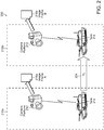
- FIG. 2 is a diagram of another exemplary image acquisition environment 200.
- the image acquisition environment 200 illustrates images at two time frames A 210a and B 210b.
- a camera platform 212 and a tank 214 are at a first position (e.g., the physical location of the camera platform 212 is in square 3x4 and the physical location of the tank 214 is in square 3x8), and the camera platform 212 receives an image frame A 216a of the tank 214.
- the camera platform 212 and the tank 214 are at a second position (e.g., the physical location of the camera platform 212 is in square 3x4 and the physical location of the tank 214 is in square 9x8), and the camera platform 212 receives an image frame B 216b of the tank 214.
- the tank 214 moved from the first position to the second position at a velocity Vt 224.
- the camera platform 212 can transmit the image frames A 216a and B 216b to an image system (not shown) for processing (e.g., integration of the image frames into an integrated image frame).
- Table 2 illustrates exemplary image information received by the camera platform 212.
- Table 2 Exemplary Image Information Image Obj ect Camera Time Image Frame A 216a Tan k 214 Camera Platform 212 05:32.21 (Time A 210a) Image Frame B 216b Tan k 214 Camera Platform 212 05:32.22 (Time B 210b) Image Frame C Tan k 214 Camera Platform 212 05:32.23 Image Frame D Tan k 214 Camera Platform 212 05:32.24
- FIG. 3 is a block diagram of an exemplary image system 310.
- the image system 310 includes a communication module 311, an image sharpness module 312, an image noise module 313, an image jitter module 314, an image integration module 315, an input device 391, an output device 392, a display device 393, a processor 394, and a storage device 395.
- the modules and devices described herein can, for example, utilize the processor 394 to execute computer executable instructions and/or include a processor to execute computer executable instructions (e.g., an encryption processing unit, a field programmable gate array processing unit, etc.).
- the image system 310 can include, for example, other modules, devices, and/or processors known in the art and/or varieties of the illustrated modules, devices, and/or processors.
- the communication module 311 receives the images (e.g., from a camera platform, from an intermediate image processing device, from a storage device, etc.).
- the communication module 311 communicates information to/from the image system 310.
- the communication module 311 can receive, for example, information associated with a camera platform.
- the information associated with the camera platform can be associated with a data signal (e.g., data signal from a camera platform, processed data signal from a camera platform, data signal from a motion sensor, data signal from a global positioning system, data signal from a location system, etc.).
- the image sharpness module 312 determines a sharpness metric for each image frame in a plurality of image frames.
- the sharpness metric is indicative of at least one of edge content and an edge size of the image frame.
- the image sharpness module 312 separates one or more horizontal edge components (e.g., a row within the image frame, set of rows within the image frame, etc.) and one or more vertical edge components (e.g., a column within the image frame, set of columns within the image frame, etc.) in each image frame in the plurality of image frames.
- the image sharpness module 312 interpolate the one or more horizontal components and the one or more vertical components for each image frame in the plurality of image frames (e.g., to achieve sub-pixel alignment, to maximize sub-pixel alignment, etc.).
- the image sharpness module 312 correlates the interpolated horizontal and vertical components to determine a pixel shift for each image frame in the plurality of image frames.
- the pixel shift is indicative of at least one of the edge content and the edge size (e.g., number of edges, size of edges, etc.) of the respective image frame.
- the pixel shift can be, for example, utilized by the image sharpness module 312 to generate an edge map for each image frame.
- the image sharpness module 312 generates an edge map for each image frame in the plurality of image frames.
- the edge map includes pixel values indicative of an edge and a non-edge.
- the image sharpness module 312 combines the pixel values in the edge map for each image frame in the plurality of image frames to form the sharpness metric.
- the image sharpness module 312 utilizes an edge detector/extractor (e.g., Sobel detector, Canny edge extractor, etc.) to generate an edge map for the image frame.
- the edge map can, for example, include pixel values of one for edges and pixel values of zero for non-edges.
- the image sharpness module 312 can, for example, sum the pixel values to generate the sharpness metric for each image frame.
- the image noise module 313 determines a noise metric for each image frame in the plurality of image frames.
- the noise metric is indicative of random variations in brightness or color in the image frame.
- the image jitter module 314 determines a jitter metric for each image frame in the plurality of image frames.
- the jitter metric is indicative of spatial shifts between the image frame and other image frames in the plurality of image frames.
- the image jitter module 314 can, for example, utilize frame to frame registration to measure the spatial shifts between image frames due to unintended motion.
- the image jitter module 314 can, for example, utilize a Fitts algorithm, correlation, and/or any other type of jitter processing technique to determine the jitter metric.
- the image jitter module 314 can, for example, utilize a Kalman filter to measure the spatial shifts between image frames due to intended motion (e.g., image pan commands, image zoom commands, etc.).
- the image frame integration module 315 integrates the one or more image frames of the plurality of image frames based on input received from the communication module 311, image sharpness module 312, image noise module 313, and the image jitter module 314.
- the image frame integration module 315 receives, for each pixel in at least one image frame of the plurality of image frames, a value representative of a sensor measurement.
- sensor measurements from each pixel can include the difference in intensity between the pixel in the current frame and those from previous frames, after registering the frames to correct for the displacement of the input images.
- statistical measurements are made and compared to thresholds indicating the persistence of the intensity differences over multiple frames. The combined information on intensity differences and their persistence is used to identify which pixels are in motion within the image.
- frame integration causes moving objects to appear blurred or smeared. In order to prevent such blurring or smearing, the image integration module 315 detects whether or not motion exists in each of the pixels of each of the image frames.
- the image frame integration module 315 detects such motion, the image frame integration module 315 generates an integrated image frame wherein each pixel having detected motion is integrated by an amount less than that of those pixels for which motion is not detected.
- the amount of integration for those pixels for which motion is detected is based on contrast levels, expected rates of motion, and noise characteristics of sensor input image data. For instance, pixels that are determined to be in motion are integrated less than those that are determined to be stationary, reducing the motion blur on the pixels associated with moving objects, while still allowing the application of heavy integration and its associated noise reduction benefits on the otherwise stationary portions of the image.
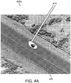
- Fig. 4A illustrates an image frame 400a in which certain pixels are erroneously identified as including motion.
- the white pixels of the image frame 400a are pixels for which motion is detected.
- the white color of pixels 405 along the lower edge of the depicted road indicates that the pixels 405a include motion.
- pixels 410 include an object in motion (e.g., a vehicle). An indication that the pixels 410 include motion is accurate.
- the image frame integration module 315 reduces erroneous detection of motion by using an averaging metric to track pixel difference over multiple frames.
- the image frame integration module 315 uses registered frame differencing to detect motion. For instance, the image frame integration module 315 calculates an average difference of the value representative of the sensor measurement of the plurality of images or a subset of the plurality of images.
- the image frame integration module 315 can calculate the average difference by normalizing a difference of the value representative of the sensor measurement of a pixel of the plurality of image frames by performing a mean absolute deviation calculation of at least one pixel between at least two image frames of the plurality of image frames.
- Fig. 4B illustrates an image frame 400b for which erroneous detections of motion is removed by using the averaging metric.
- the erroneous detection of motion in pixels 405 is no longer present.
- the image frame integration module 315 detects motion in a pixel of an image frame if the average difference of the value representative of the sensor measurement is greater than a scale factor times the average difference and the average difference is greater than a noise threshold.
- the scale factor is based on a statistical dispersion of data resulting from normalizing the difference of the value representative of the sensor measurement of a pixel of the plurality of image frames and sensor noise, registration accuracy, and changes in the image from frame-to-frame such as rotation, scale and perspective.
- the noise threshold is based on measured image noise and a type of sensor providing the sensor measurement.
- a trailing end of the moving object tends to blur. This occurs because the average difference of the value representative of the sensor measurements for pixels corresponding to the trailing end increases as the moving object reveals the background stationary image. This effect causes the pixels at the trailing end of a moving object to be misidentified as pixels associated with motion.
- Fig. 5A illustrates an image frame 500a that includes a blurred trailing end 515a of a moving object.
- the image frame integration module 315 assigns a persistent count for each pixel for which motion is detected. In particular, the persistent is set when the average difference is greater than the noise threshold and greater than a scale factor times the average difference.
- the persistent count is based on a typical vehicle's size and speed, and range of an image sensor to the target (e.g., the vehicle).
- Fig. 5B illustrates an image frame 500b.
- the image frame integration module 315 utilizes the persistent count to assist in identifying movement in a trailing end of the moving object (i.e., pixels which are white).
- the image frame integration module 315 can also utilize a noise filter to further reduce false detections of movement.
- the image frame integration module 315 assumes that a true moving object should be made up of a cluster of moving pixels.
- the image frame integration module 315 determines if a certain percentage of pixels within a predetermined region (e.g., a 9x9 pixel region) around the pixel identified as including motion also include motion. The percentage of pixels is predetermined based on image and sensor characteristics, and the actual percentage is tuned for each application.
- the image frame integration module 315 utilizing a morphological spreading filter. As stated above, the image frame integration module 315 assumes that a true moving object should not be a collection of disconnected discrete pixels, and should be made up of a cluster of pixels for which motion is detected. This spreading filter is applied to fill in and extend the group of motion pixels associated with the moving object and create a uniform motion mask defining the boundaries of the moving object within the frame.
- Fig. 6A illustrates an image frame 600a that includes a group of low contrast pixels 630 corresponding to a moving object for which motion is not detected (e.g., the pixels are not white and are in grayscale).
- the image frame integration module 315 utilizing a morphological spreading filter to correctly identify movement in such pixels.
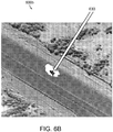
- Fig. 6B illustrates an image frame 600b that correctly identifies motion in the low contrast pixels 630.
- the image frame integration module 315 then integrates each pixel in each of the plurality of image frames by an amount based on whether the pixel includes motion.
- the display device 393 displays information associated with the image system 310 (e.g., status information, configuration information, etc.).
- the processor 394 executes the operating system and/or any other computer executable instructions for the image system 310 (e.g., executes applications, etc.).
- the memory 395 stores the images (e.g., actual image, processed image, etc.), the integrated image frames, and/or any other data associated with the image system 310.
- the memory 395 can store image information and/or any other data associated with the image system 310.
- the memory 395 can include a plurality of storage devices and/or the image system 310 can include a plurality of storage devices (e.g., an image storage device, an integrated image storage device, etc.).
- the memory 395 can include, for example, long-term storage (e.g., a hard drive, a tape storage device, flash memory, etc.), short-term storage (e.g., a random access memory, a graphics memory, etc.), and/or any other type of computer readable storage.
- Fig. 7 is a flow diagram of a method 700 for integrating image frames in accordance with an example embodiment of the present invention.
- the method 700 begins at 705.
- the method includes receiving for each pixel in at least one image frame a value representative of a sensor measurement.
- the method includes calculating an average difference of the value representative of the sensor measurement over a subset of the plurality of image frames.
- the method includes detecting motion in at least one pixel of the image frame in the plurality of image frames based on the calculated average difference of the value representative of the sensor measurement over the subset of the plurality of image frames. The detected motion is of an object captured in the plurality of image frames.
- the method includes generating an integrated image frame wherein each pixel having detected motion is integrated by an amount less than that of those pixels for which motion is not detected.
- the amount of frame integration is based on contrast levels, expected rates of motion, and noise characteristics of sensor input image data.
- the above-described systems and methods can be implemented in digital electronic circuitry, in computer hardware, firmware, and/or software.
- the implementation can be as a computer program product.
- the implementation can, for example, be in a machine-readable storage device, for execution by, or to control the operation of, data processing apparatus.
- the implementation can, for example, be a programmable processor, a computer, and/or multiple computers.
- Further example embodiments of the present disclosure may be configured using a computer program product; for example, controls may be programmed in software for implementing example embodiments of the present disclosure. Further example embodiments of the present disclosure may include a non-transitory computer readable medium containing instruction that may be executed by a processor, and, when executed, cause the processor to complete methods described herein. It should be understood that elements of the block and flow diagrams described herein may be implemented in software, hardware, firmware, or other similar implementation determined in the future. In addition, the elements of the block and flow diagrams described herein may be combined or divided in any manner in software, hardware, or firmware. If implemented in software, the software may be written in any language that can support the example embodiments disclosed herein.
- the software may be stored in any form of computer readable medium, such as random access memory (RAM), read only memory (ROM), compact disk read only memory (CD-ROM), and so forth.
- RAM random access memory
- ROM read only memory
- CD-ROM compact disk read only memory
- a general purpose or application specific processor loads and executes software in a manner well understood in the art.
- the block and flow diagrams may include more or fewer elements, be arranged or oriented differently, or be represented differently. It should be understood that implementation may dictate the block, flow, and/or network diagrams and the number of block and flow diagrams illustrating the execution of embodiments of the present disclosure.
- a computer program can be written in any form of programming language, including compiled and/or interpreted languages, and the computer program can be deployed in any form, including as a stand-alone program or as a subroutine, element, and/or other unit suitable for use in a computing environment.
- a computer program can be deployed to be executed on one computer or on multiple computers at one site.
- Method steps can be performed by one or more programmable processors executing a computer program to perform functions of the present disclosure by operating on input data and generating output. Method steps can also be performed by and an apparatus can be implemented as special purpose logic circuitry.
- the circuitry can, for example, be a FPGA (field programmable gate array) and/or an ASIC (application-specific integrated circuit).
- Subroutines and software agents can refer to portions of the computer program, the processor, the special circuitry, software, and/or hardware that implement that functionality.
- processors suitable for the execution of a computer program include, by way of example, both general and special purpose microprocessors, and any one or more processors of any kind of digital computer.
- a processor receives instructions and data from a read-only memory or a random access memory or both.
- the essential elements of a computer are a processor for executing instructions and one or more memory devices for storing instructions and data.
- a computer can include, can be operatively coupled to receive data from and/or transfer data to one or more mass storage devices for storing data (e.g., magnetic, magneto-optical disks, or optical disks).
- Data transmission and instructions can also occur over a communications network.
- Information carriers suitable for embodying computer program instructions and data include all forms of non-volatile memory, including by way of example semiconductor memory devices.
- the information carriers can, for example, be EPROM, EEPROM, flash memory devices, magnetic disks, internal hard disks, removable disks, magneto-optical disks, CD-ROM, and/or DVD-ROM disks.
- the processor and the memory can be supplemented by, and/or incorporated in special purpose logic circuitry.
- the above described techniques can be implemented on a computer having a display device.
- the display device can, for example, be a cathode ray tube (CRT) and/or a liquid crystal display (LCD) monitor.
- CTR cathode ray tube
- LCD liquid crystal display
- the interaction with a user can, for example, be a display of information to the user and a keyboard and a pointing device (e.g., a mouse or a trackball) by which the user can provide input to the computer (e.g., interact with a user interface element).
- Other kinds of devices can be used to provide for interaction with a user.
- Other devices can, for example, be feedback provided to the user in any form of sensory feedback (e.g., visual feedback, auditory feedback, or tactile feedback).
- Input from the user can, for example, be received in any form, including acoustic, speech, and/or tactile input.
- the above described techniques can be implemented in a distributed computing system that includes a back-end component.
- the back-end component can, for example, be a data server, a middleware component, and/or an application server.
- the above described techniques can be implemented in a distributing computing system that includes a front-end component.
- the front-end component can, for example, be a client computer having a graphical user interface, a Web browser through which a user can interact with an example implementation, and/or other graphical user interfaces for a transmitting device.
- the components of the system can be interconnected by any form or medium of digital data communication (e.g., a communication network). Examples of communication networks include a local area network (LAN), a wide area network (WAN), the Internet, wired networks, and/or wireless networks.
- LAN local area network
- WAN wide area network
- the Internet wired networks, and/or wireless networks.
- the system can include clients and servers.
- a client and a server are generally remote from each other and typically interact through a communication network.
- the relationship of client and server arises by virtue of computer programs running on the respective computers and having a client-server relationship to each other.
- Packet-based networks can include, for example, the Internet, a carrier internet protocol (IP) network (e.g., local area network (LAN), wide area network (WAN), campus area network (CAN), metropolitan area network (MAN), home area network (HAN)), a private IP network, an IP private branch exchange (IPBX), a wireless network (e.g., radio access network (RAN), 802.11 network, 802.16 network, general packet radio service (GPRS) network, HiperLAN), and/or other packet-based networks.
- IP carrier internet protocol
- LAN local area network
- WAN wide area network
- CAN campus area network
- MAN metropolitan area network
- HAN home area network
- IP network IP private branch exchange
- wireless network e.g., radio access network (RAN), 802.11 network, 802.16 network, general packet radio service (GPRS) network, HiperLAN
- GPRS general packet radio service
- HiperLAN HiperLAN
- Circuit-based networks can include, for example, the public switched telephone network (PSTN), a private branch exchange (PBX), a wireless network (e.g., RAN, bluetooth, code-division multiple access (CDMA) network, time division multiple access (TDMA) network, global system for mobile communications (GSM) network), and/or other circuit-based networks.
- PSTN public switched telephone network
- PBX private branch exchange
- CDMA code-division multiple access
- TDMA time division multiple access
- GSM global system for mobile communications
- the transmitting device can include, for example, a computer, a computer with a browser device, a telephone, an IP phone, a mobile device (e.g., cellular phone, personal digital assistant (PDA) device, laptop computer, electronic mail device), and/or other communication devices.
- the browser device includes, for example, a computer (e.g., desktop computer, laptop computer) with a world wide web browser (e.g., Microsoft® Internet Explorer® available from Microsoft Corporation, Mozilla® Firefox available from Mozilla Corporation).
- the mobile computing device includes, for example, a Blackberry®.
- Comprise, include, and/or plural forms of each are open ended and include the listed parts and can include additional parts that are not listed. And/or is open ended and includes one or more of the listed parts and combinations of the listed parts.
Landscapes
- Engineering & Computer Science (AREA)
- Multimedia (AREA)
- Signal Processing (AREA)
- Physics & Mathematics (AREA)
- General Physics & Mathematics (AREA)
- Theoretical Computer Science (AREA)
- Image Analysis (AREA)
Description
- Generally, the display of images is degraded by motion blur and noise. Prior attempts at image frame integration reduce noise and increase sensor performance. However, the prior attempts at image frame integration are often degraded by motion blur and noise. Thus, a need exists in the art for improved image frame integration.
-
US2004/252199 discloses an imaging system that disables pixel integration for images within frames that are identified as moving while enables pixel integration for images that are not moving. The system may implement a frame-averaging type of integration or recursive types of frame integration, or may refrain from performing frame integration. On a pixel-by-pixel basis, the system may compare a pixel from frame memory with a corresponding pixel of an input frame and may disable pixel integration for the pixel when a difference between the compared pixels exceeds a threshold. One of the integration processes may be performed on the pixels when the difference does not exceed the threshold.; When frame integration is disabled or deselected (e.g., for pixels having motion), the frame memory may be bypassed and a self-integration may be performed with corresponding pixels from a current frame effectively resulting in no integration. Some embodiments may use multiple thresholds, and may use different integration algorithms depending on conditions within a scene. -
US 4 679 086 A discloses that noise smoothing of imaging data is performed using frame integration, by averaging pixels over time instead of space, without resulting in a smear of moving objects by: sensing image motion; and enabling frame integration on only stationary scene pixels. Image motion is sensed by: producing a differencing signal which indicates the difference between new image data and frame integrated data; and comparing the differencing signal with a threshold signal. When the threshold signal has a value which approximately equals expected image noise, then the image data processed by a particular pixel may be deemed non-moving when the difference signal is less than the threshold signal, and the image data may be deemed to depict moving objects otherwise. Finally, image data is conducted unprocessed to the display for moving scene pixels, while frame integrated image data is conducted to the display for stationary scene pixels. -
WO 2011/019461 A1 discloses a night vision device and method for filtering a series of image frames that depict a moving subject, which thereby improves the signal-to-noise ratio of each image frame, is provided. A composite image is formed for each image frame by combining pixel values in a current image frame with pixel values in composite images corresponding to image frames acquired before the current image frame. Additionally, pixels values in image frames acquired subsequent to the acquisition of the current image frame are included when forming the composite image. A bi not directional recursive filter is used to weight the contributions from the previous composite images and subsequent image frames with a decay constant. Motion of the imaging system is optionally compensated for by establishing a moving reference frame and shifting the image frames to account for this motion; thus, registering the image frames before filtering the current image frame. -
EP 2 063 390 A1 discloses an adaptive image processing device that performs image processing with a simple configuration on a composite image including areas having different characteristics by changing a process depending on the number of combined images in each area of the composite image configured by combining a plurality of images. The image processing device acquires a plurality of images and generates a composite image. When the composite image is generated, the image processing device realizes a process of determining the number of combined images for detecting the number of images to be combined for each area of the composite image and holding the number as information about the number of combined images, and an image processing parameter switching process for switching a parameter of image processing to be performed on each area of the composite image according to the information about the number of combined images. - In one aspect, the present disclosure provides a method for integrating image frames according to claim 1.
- In another aspect, the present disclosure provides a system for integrating image frames according to claim 6.
- In another aspect, the present disclosure provides a non-transitory computer-readable medium according to claim 11.
- Other aspects of the invention are defined in the dependent claims.
- The foregoing and other objects, features and advantages will be apparent from the following more particular description of the embodiments, as illustrated in the accompanying drawings in which like reference characters refer to the same parts throughout the different views. The drawings are not necessarily to scale, emphasis instead being placed upon illustrating the principles of the embodiments.
-
FIG. 1 is a diagram of an exemplary image acquisition environment in accordance with an example embodiment of the present disclosure. -
FIG. 2 is a diagram of another exemplary image acquisition environment in accordance with an example embodiment of the present disclosure. -
FIG. 3 is a block diagram of an exemplary image system in accordance with an example embodiment of the present disclosure. -
Fig. 4A illustrates an image frame n which certain pixels are erroneously identified as including motion in accordance with an example embodiment of the present disclosure. -
Fig. 4B illustrates an image frame for which erroneous detections of motion is removed by using an averaging metric in accordance with an example embodiment of the present disclosure. -
Fig. 5A illustrates an image frame that includes a blurred trailing end of a moving object in accordance with an example embodiment of the present disclosure. -
Fig. 5B illustrates an image frame utilizes a persistent count to assist in identifying movement in a trailing end of the moving object in accordance with an example embodiment of the present disclosure. -
Fig. 6A illustrates an image frame that includes a group of low contrast pixels corresponding to a moving object for which motion is not detected in accordance with an example embodiment of the present disclosure. -
Fig. 6B illustrates an image frame that correctly identifies motion in the low contrast pixels in accordance with an example embodiment of the present disclosure. -
Fig. 7 is a flow diagram of a method for integrating image frames in accordance with an example embodiment of the present invention. -
FIG. 1 is a diagram of an exemplaryimage acquisition environment 100. Theenvironment 100 includes animage console 110, animage system 120, and acamera platform 130. Animage operator 115 views a plurality of objects utilizing theimage console 110. The plurality of objects includes a tank 132, a car 134, a tanker trailer 136, and a truck 138. The camera platform 130 (e.g., optical camera platform, infrared camera platform, etc.) receives optical waves, infrared waves, and/or any other type of waveform to form an image of one or more of the plurality of objects. Thecamera platform 130 communicates data (e.g., digital representation of an image of the tank 132, optical representation of an image of the car 134, etc.) to theimage system 120. - The
image system 120 analyzes the received video and/or image frames to integrate the image frames (e.g., a single snapshot of the image at a specified time, a sub-part of the image, etc.). For example, a one second video of an object includes ten image frames of the object. In this example, theimage system 120 integrates the ten image frames to form an integrated image frame with enhanced resolution of the object. Theimage system 120 can store the integrated image for further analysis and/or transmit the integrated image to theimage console 110 for viewing and/or analysis by theimage operator 115. - Although
FIG. 1 illustrates asingle camera platform 130, theenvironment 100 can utilize any number of camera platforms (e.g., ten camera platforms, one hundred camera platforms, etc.). For example, theimage system 120 can receive images from any number of camera platforms for the same object or different objects (as illustrated in Table 1). In other examples, thesingle camera platform 130 can include a plurality of cameras and/or other types of image capture devices (e.g., motion sensor, environmental sensor, heat sensor, etc.). - Table 1 illustrates exemplary image information received by a plurality of camera platforms and transmitted to the
image system 120.Table 1. Exemplary Image Information Image Object Camera Time A34 Tank 142 Airplane BZ 03:32.21 A35 Tank 142 Airplane BZ 03:32.22 B34 Tank 142 Border Wall RT 03:32.22 C56 Tank 142 Command 03:32.21 Carrier GH D32 Tank 142 Satellite CB 03:32.20 -
FIG. 2 is a diagram of another exemplaryimage acquisition environment 200. Theimage acquisition environment 200 illustrates images at two time frames A 210a and B 210b. Attime A 210a, acamera platform 212 and atank 214 are at a first position (e.g., the physical location of thecamera platform 212 is in square 3x4 and the physical location of thetank 214 is in square 3x8), and thecamera platform 212 receives animage frame A 216a of thetank 214. Attime B 210b, thecamera platform 212 and thetank 214 are at a second position (e.g., the physical location of thecamera platform 212 is in square 3x4 and the physical location of thetank 214 is in square 9x8), and thecamera platform 212 receives animage frame B 216b of thetank 214. During the time period betweentime A 210a andtime B 210b, thetank 214 moved from the first position to the second position at avelocity Vt 224. Thecamera platform 212 can transmit the image frames A 216a andB 216b to an image system (not shown) for processing (e.g., integration of the image frames into an integrated image frame). - Table 2 illustrates exemplary image information received by the
camera platform 212.Table 2. Exemplary Image Information Image Obj ect Camera Time Image Frame A 216aTan k 214Camera Platform 21205:32.21 ( Time A 210a)Image Frame B 216bTan k 214 Camera Platform 21205:32.22 ( Time B 210b)Image Frame C Tan k 214 Camera Platform 21205:32.23 Image Frame D Tan k 214 Camera Platform 21205:32.24 -
FIG. 3 is a block diagram of anexemplary image system 310. Theimage system 310 includes acommunication module 311, animage sharpness module 312, animage noise module 313, animage jitter module 314, animage integration module 315, aninput device 391, anoutput device 392, adisplay device 393, aprocessor 394, and astorage device 395. The modules and devices described herein can, for example, utilize theprocessor 394 to execute computer executable instructions and/or include a processor to execute computer executable instructions (e.g., an encryption processing unit, a field programmable gate array processing unit, etc.). It should be understood that theimage system 310 can include, for example, other modules, devices, and/or processors known in the art and/or varieties of the illustrated modules, devices, and/or processors. - The
communication module 311 receives the images (e.g., from a camera platform, from an intermediate image processing device, from a storage device, etc.). Thecommunication module 311 communicates information to/from theimage system 310. Thecommunication module 311 can receive, for example, information associated with a camera platform. The information associated with the camera platform can be associated with a data signal (e.g., data signal from a camera platform, processed data signal from a camera platform, data signal from a motion sensor, data signal from a global positioning system, data signal from a location system, etc.). - The
image sharpness module 312 determines a sharpness metric for each image frame in a plurality of image frames. The sharpness metric is indicative of at least one of edge content and an edge size of the image frame. - In other examples, the
image sharpness module 312 separates one or more horizontal edge components (e.g., a row within the image frame, set of rows within the image frame, etc.) and one or more vertical edge components (e.g., a column within the image frame, set of columns within the image frame, etc.) in each image frame in the plurality of image frames. In some examples, theimage sharpness module 312 interpolate the one or more horizontal components and the one or more vertical components for each image frame in the plurality of image frames (e.g., to achieve sub-pixel alignment, to maximize sub-pixel alignment, etc.). In other examples, theimage sharpness module 312 correlates the interpolated horizontal and vertical components to determine a pixel shift for each image frame in the plurality of image frames. The pixel shift is indicative of at least one of the edge content and the edge size (e.g., number of edges, size of edges, etc.) of the respective image frame. The pixel shift can be, for example, utilized by theimage sharpness module 312 to generate an edge map for each image frame. - In some examples, the
image sharpness module 312 generates an edge map for each image frame in the plurality of image frames. The edge map includes pixel values indicative of an edge and a non-edge. In other examples, theimage sharpness module 312 combines the pixel values in the edge map for each image frame in the plurality of image frames to form the sharpness metric. - In other examples, the
image sharpness module 312 utilizes an edge detector/extractor (e.g., Sobel detector, Canny edge extractor, etc.) to generate an edge map for the image frame. The edge map can, for example, include pixel values of one for edges and pixel values of zero for non-edges. Theimage sharpness module 312 can, for example, sum the pixel values to generate the sharpness metric for each image frame. - The
image noise module 313 determines a noise metric for each image frame in the plurality of image frames. The noise metric is indicative of random variations in brightness or color in the image frame. - The
image jitter module 314 determines a jitter metric for each image frame in the plurality of image frames. The jitter metric is indicative of spatial shifts between the image frame and other image frames in the plurality of image frames. Theimage jitter module 314 can, for example, utilize frame to frame registration to measure the spatial shifts between image frames due to unintended motion. Theimage jitter module 314 can, for example, utilize a Fitts algorithm, correlation, and/or any other type of jitter processing technique to determine the jitter metric. Theimage jitter module 314 can, for example, utilize a Kalman filter to measure the spatial shifts between image frames due to intended motion (e.g., image pan commands, image zoom commands, etc.). - The image
frame integration module 315 integrates the one or more image frames of the plurality of image frames based on input received from thecommunication module 311,image sharpness module 312,image noise module 313, and theimage jitter module 314. - In particular, the image
frame integration module 315 receives, for each pixel in at least one image frame of the plurality of image frames, a value representative of a sensor measurement. For example, sensor measurements from each pixel can include the difference in intensity between the pixel in the current frame and those from previous frames, after registering the frames to correct for the displacement of the input images. Additionally, statistical measurements are made and compared to thresholds indicating the persistence of the intensity differences over multiple frames. The combined information on intensity differences and their persistence is used to identify which pixels are in motion within the image. In general, frame integration causes moving objects to appear blurred or smeared. In order to prevent such blurring or smearing, theimage integration module 315 detects whether or not motion exists in each of the pixels of each of the image frames. Once the imageframe integration module 315 detects such motion, the imageframe integration module 315 generates an integrated image frame wherein each pixel having detected motion is integrated by an amount less than that of those pixels for which motion is not detected. In an example, the amount of integration for those pixels for which motion is detected is based on contrast levels, expected rates of motion, and noise characteristics of sensor input image data. For instance, pixels that are determined to be in motion are integrated less than those that are determined to be stationary, reducing the motion blur on the pixels associated with moving objects, while still allowing the application of heavy integration and its associated noise reduction benefits on the otherwise stationary portions of the image. - In some situations, motion may be erroneously detected in some pixels. Such detection errors can be caused by, for example, misregistration of image frames, scale changes, rotations, perspective changes, and interlace effects.
Fig. 4A illustrates animage frame 400a in which certain pixels are erroneously identified as including motion. In particular, the white pixels of theimage frame 400a are pixels for which motion is detected. For example, the white color ofpixels 405 along the lower edge of the depicted road indicates that the pixels 405a include motion. However, such an indication is clearly erroneous because the pixels 405a do not include an object in motion. In contrast,pixels 410 include an object in motion (e.g., a vehicle). An indication that thepixels 410 include motion is accurate. - Referring back to
Fig. 3 , the imageframe integration module 315 reduces erroneous detection of motion by using an averaging metric to track pixel difference over multiple frames. In an example, the imageframe integration module 315 uses registered frame differencing to detect motion. For instance, the imageframe integration module 315 calculates an average difference of the value representative of the sensor measurement of the plurality of images or a subset of the plurality of images. The imageframe integration module 315 can calculate the average difference by normalizing a difference of the value representative of the sensor measurement of a pixel of the plurality of image frames by performing a mean absolute deviation calculation of at least one pixel between at least two image frames of the plurality of image frames. -
Fig. 4B illustrates animage frame 400b for which erroneous detections of motion is removed by using the averaging metric. In particular, the erroneous detection of motion inpixels 405 is no longer present. - Referring back to
Fig. 3 , the imageframe integration module 315 detects motion in a pixel of an image frame if the average difference of the value representative of the sensor measurement is greater than a scale factor times the average difference and the average difference is greater than a noise threshold. The scale factor is based on a statistical dispersion of data resulting from normalizing the difference of the value representative of the sensor measurement of a pixel of the plurality of image frames and sensor noise, registration accuracy, and changes in the image from frame-to-frame such as rotation, scale and perspective. The noise threshold is based on measured image noise and a type of sensor providing the sensor measurement. - For moving objects, a trailing end of the moving object tends to blur. This occurs because the average difference of the value representative of the sensor measurements for pixels corresponding to the trailing end increases as the moving object reveals the background stationary image. This effect causes the pixels at the trailing end of a moving object to be misidentified as pixels associated with motion.
Fig. 5A illustrates animage frame 500a that includes a blurred trailingend 515a of a moving object. In order to compensate for such blurring, the imageframe integration module 315 assigns a persistent count for each pixel for which motion is detected. In particular, the persistent is set when the average difference is greater than the noise threshold and greater than a scale factor times the average difference. The persistent count is based on a typical vehicle's size and speed, and range of an image sensor to the target (e.g., the vehicle).Fig. 5B illustrates animage frame 500b. As illustrated, the imageframe integration module 315 utilizes the persistent count to assist in identifying movement in a trailing end of the moving object (i.e., pixels which are white). - In addition, the image
frame integration module 315 can also utilize a noise filter to further reduce false detections of movement. In particular, the imageframe integration module 315 assumes that a true moving object should be made up of a cluster of moving pixels. Thus, for each pixel that is identified as including motion, the imageframe integration module 315 determines if a certain percentage of pixels within a predetermined region (e.g., a 9x9 pixel region) around the pixel identified as including motion also include motion. The percentage of pixels is predetermined based on image and sensor characteristics, and the actual percentage is tuned for each application. - In some situations, lower contrast pixels in an image frame corresponding to a moving object may not be identified as including motion when the pixel difference calculations may not exceed the input sensor noise level thresholds. In order to prevent such a situation, the image
frame integration module 315 utilizing a morphological spreading filter. As stated above, the imageframe integration module 315 assumes that a true moving object should not be a collection of disconnected discrete pixels, and should be made up of a cluster of pixels for which motion is detected. This spreading filter is applied to fill in and extend the group of motion pixels associated with the moving object and create a uniform motion mask defining the boundaries of the moving object within the frame. -
Fig. 6A illustrates animage frame 600a that includes a group oflow contrast pixels 630 corresponding to a moving object for which motion is not detected (e.g., the pixels are not white and are in grayscale). In order to prevent such a scenario, the imageframe integration module 315 utilizing a morphological spreading filter to correctly identify movement in such pixels.Fig. 6B illustrates animage frame 600b that correctly identifies motion in thelow contrast pixels 630. The imageframe integration module 315 then integrates each pixel in each of the plurality of image frames by an amount based on whether the pixel includes motion. - Referring back to
Fig. 3 , thedisplay device 393 displays information associated with the image system 310 (e.g., status information, configuration information, etc.). Theprocessor 394 executes the operating system and/or any other computer executable instructions for the image system 310 (e.g., executes applications, etc.). - The
memory 395 stores the images (e.g., actual image, processed image, etc.), the integrated image frames, and/or any other data associated with theimage system 310. Thememory 395 can store image information and/or any other data associated with theimage system 310. Thememory 395 can include a plurality of storage devices and/or theimage system 310 can include a plurality of storage devices (e.g., an image storage device, an integrated image storage device, etc.). Thememory 395 can include, for example, long-term storage (e.g., a hard drive, a tape storage device, flash memory, etc.), short-term storage (e.g., a random access memory, a graphics memory, etc.), and/or any other type of computer readable storage. -
Fig. 7 is a flow diagram of amethod 700 for integrating image frames in accordance with an example embodiment of the present invention. Themethod 700 begins at 705. At 710, the method includes receiving for each pixel in at least one image frame a value representative of a sensor measurement. Also, at 715, the method includes calculating an average difference of the value representative of the sensor measurement over a subset of the plurality of image frames. The method, at 720, includes detecting motion in at least one pixel of the image frame in the plurality of image frames based on the calculated average difference of the value representative of the sensor measurement over the subset of the plurality of image frames. The detected motion is of an object captured in the plurality of image frames. Further, at 725, the method includes generating an integrated image frame wherein each pixel having detected motion is integrated by an amount less than that of those pixels for which motion is not detected. The amount of frame integration is based on contrast levels, expected rates of motion, and noise characteristics of sensor input image data. At 730, the method ends. - The above-described systems and methods can be implemented in digital electronic circuitry, in computer hardware, firmware, and/or software. The implementation can be as a computer program product. The implementation can, for example, be in a machine-readable storage device, for execution by, or to control the operation of, data processing apparatus. The implementation can, for example, be a programmable processor, a computer, and/or multiple computers.
- Further example embodiments of the present disclosure may be configured using a computer program product; for example, controls may be programmed in software for implementing example embodiments of the present disclosure. Further example embodiments of the present disclosure may include a non-transitory computer readable medium containing instruction that may be executed by a processor, and, when executed, cause the processor to complete methods described herein. It should be understood that elements of the block and flow diagrams described herein may be implemented in software, hardware, firmware, or other similar implementation determined in the future. In addition, the elements of the block and flow diagrams described herein may be combined or divided in any manner in software, hardware, or firmware. If implemented in software, the software may be written in any language that can support the example embodiments disclosed herein. The software may be stored in any form of computer readable medium, such as random access memory (RAM), read only memory (ROM), compact disk read only memory (CD-ROM), and so forth. In operation, a general purpose or application specific processor loads and executes software in a manner well understood in the art. It should be understood further that the block and flow diagrams may include more or fewer elements, be arranged or oriented differently, or be represented differently. It should be understood that implementation may dictate the block, flow, and/or network diagrams and the number of block and flow diagrams illustrating the execution of embodiments of the present disclosure.
- A computer program can be written in any form of programming language, including compiled and/or interpreted languages, and the computer program can be deployed in any form, including as a stand-alone program or as a subroutine, element, and/or other unit suitable for use in a computing environment. A computer program can be deployed to be executed on one computer or on multiple computers at one site.
- Method steps can be performed by one or more programmable processors executing a computer program to perform functions of the present disclosure by operating on input data and generating output. Method steps can also be performed by and an apparatus can be implemented as special purpose logic circuitry. The circuitry can, for example, be a FPGA (field programmable gate array) and/or an ASIC (application-specific integrated circuit). Subroutines and software agents can refer to portions of the computer program, the processor, the special circuitry, software, and/or hardware that implement that functionality.
- Processors suitable for the execution of a computer program include, by way of example, both general and special purpose microprocessors, and any one or more processors of any kind of digital computer. Generally, a processor receives instructions and data from a read-only memory or a random access memory or both. The essential elements of a computer are a processor for executing instructions and one or more memory devices for storing instructions and data. Generally, a computer can include, can be operatively coupled to receive data from and/or transfer data to one or more mass storage devices for storing data (e.g., magnetic, magneto-optical disks, or optical disks).
- Data transmission and instructions can also occur over a communications network. Information carriers suitable for embodying computer program instructions and data include all forms of non-volatile memory, including by way of example semiconductor memory devices. The information carriers can, for example, be EPROM, EEPROM, flash memory devices, magnetic disks, internal hard disks, removable disks, magneto-optical disks, CD-ROM, and/or DVD-ROM disks. The processor and the memory can be supplemented by, and/or incorporated in special purpose logic circuitry.
- To provide for interaction with a user, the above described techniques can be implemented on a computer having a display device. The display device can, for example, be a cathode ray tube (CRT) and/or a liquid crystal display (LCD) monitor. The interaction with a user can, for example, be a display of information to the user and a keyboard and a pointing device (e.g., a mouse or a trackball) by which the user can provide input to the computer (e.g., interact with a user interface element). Other kinds of devices can be used to provide for interaction with a user. Other devices can, for example, be feedback provided to the user in any form of sensory feedback (e.g., visual feedback, auditory feedback, or tactile feedback). Input from the user can, for example, be received in any form, including acoustic, speech, and/or tactile input.
- The above described techniques can be implemented in a distributed computing system that includes a back-end component. The back-end component can, for example, be a data server, a middleware component, and/or an application server. The above described techniques can be implemented in a distributing computing system that includes a front-end component. The front-end component can, for example, be a client computer having a graphical user interface, a Web browser through which a user can interact with an example implementation, and/or other graphical user interfaces for a transmitting device. The components of the system can be interconnected by any form or medium of digital data communication (e.g., a communication network). Examples of communication networks include a local area network (LAN), a wide area network (WAN), the Internet, wired networks, and/or wireless networks.
- The system can include clients and servers. A client and a server are generally remote from each other and typically interact through a communication network. The relationship of client and server arises by virtue of computer programs running on the respective computers and having a client-server relationship to each other.
- Packet-based networks can include, for example, the Internet, a carrier internet protocol (IP) network (e.g., local area network (LAN), wide area network (WAN), campus area network (CAN), metropolitan area network (MAN), home area network (HAN)), a private IP network, an IP private branch exchange (IPBX), a wireless network (e.g., radio access network (RAN), 802.11 network, 802.16 network, general packet radio service (GPRS) network, HiperLAN), and/or other packet-based networks. Circuit-based networks can include, for example, the public switched telephone network (PSTN), a private branch exchange (PBX), a wireless network (e.g., RAN, bluetooth, code-division multiple access (CDMA) network, time division multiple access (TDMA) network, global system for mobile communications (GSM) network), and/or other circuit-based networks.
- The transmitting device can include, for example, a computer, a computer with a browser device, a telephone, an IP phone, a mobile device (e.g., cellular phone, personal digital assistant (PDA) device, laptop computer, electronic mail device), and/or other communication devices. The browser device includes, for example, a computer (e.g., desktop computer, laptop computer) with a world wide web browser (e.g., Microsoft® Internet Explorer® available from Microsoft Corporation, Mozilla® Firefox available from Mozilla Corporation). The mobile computing device includes, for example, a Blackberry®.
- Comprise, include, and/or plural forms of each are open ended and include the listed parts and can include additional parts that are not listed. And/or is open ended and includes one or more of the listed parts and combinations of the listed parts.
- One skilled in the art will realize the present disclosure may be embodied in other specific forms without departing from the essential characteristics thereof. The foregoing embodiments are therefore to be considered in all respects illustrative rather than limiting of the present disclosure described herein. Scope of the present disclosure is thus indicated by the appended claims.
Claims (11)
- A method (700) for integrating image frames, the method (700) comprising:receiving (710) for each pixel in at least one image frame in a plurality of image frames a value representative of a sensor measurement;calculating (715) an average difference of the value representative of the sensor measurement over a subset of the plurality of image frames;detecting (720) motion in at least one pixel of the at least one image frame in the plurality of image frames based on the calculated average difference of the value representative of the sensor measurement over the subset of the plurality of image frames, where the detected motion is of an object captured in the plurality of image frames,wherein detecting (720) motion includes detecting initial motion in the at least one pixel of the image frame in the plurality of image frames if the average difference is greater than a scale factor times the average difference and the average difference is greater than a noise threshold, andwherein the scale factor is based on a statistical dispersion of data resulting from normalizing the difference of the value representative of the sensor measurement of a pixel of the plurality of image frames and sensor noise, registration accuracy, and changes in the image from frame-to-frame such as rotation, scale and perspective;assigning a persistence count for each of the at least one pixel of the image frame for which initial motion is detected when the average difference is greater than the noise threshold and greater than the scale factor times the average difference, the persistence count to assist in identifying movement in the trailing end of a moving object, wherein persistence of intensity differences over multiple image frames assists in identifying which pixels are in motion within the image; andgenerating (725) an integrated image frame wherein each pixel being identified as a pixel in motion is integrated by an amount of frame integration, the amount of frame integration being less than that of those pixels for which motion is not detected, wherein the amount of frame integration is based on contrast levels, expected rates of motion, and noise characteristics of sensor input image data.
- The method (700) of claim 1 wherein calculating (715) the average difference includes normalizing a difference of the value representative of the sensor measurement of a pixel of the plurality of image frames by performing a mean absolute deviation calculation of at least one pixel between at least two image frames of the plurality of image frames.
- The method (700) of claim 1 wherein the noise threshold is based on measured image noise and a type of sensor providing the sensor measurement
- The method (700) of claim 1 wherein the persistent count is based on a typical vehicle size and speed, and a range of an image sensor to a target.
- The method (700) of claim 1 further comprising reducing false detections of motions by applying a noise filter to each of the at least one pixel of the image frame for which motion is detected; and
preferably further comprising applying a morphological spreading filter to those pixels for which motion is still detected; and
preferably further comprising thresholding the output of the morphological spreading filter, the thresholding providing a final identification of motion in the at least one pixel of the image frame in the plurality of image frames. - A system (310) for integrating image frames, the system (310) comprising:a memory (395);one or more processors (394); andan image integration module (315), using the one or more processors (394), configured to:receive (710) for each pixel in at least one image frame in a plurality of image frames a value representative of a sensor measurement;calculate (715) an average difference of the value representative of the sensor measurement over a subset of the plurality of image frames;detect (720) motion in at least one pixel of the at least one image frame in the plurality of image frames based on the calculated average difference of the value representative of the sensor measurement over the subset of the plurality of image frames, where the detected motion is of an object captured in the plurality of image frames,wherein the image integration module (315), using the one or more processors (394), is further configured to detect initial motion in the at least one pixel of the image frame in the plurality of image frames if the average difference is greater than a scale factor times the average difference and the average difference is greater than a noise threshold; andwherein the scale factor is based on a statistical dispersion of data resulting from normalizing the difference of the value representative of the sensor measurement of a pixel of the plurality of image frames and sensor noise, registration accuracy, and changes in the image from frame-to-frame such as rotation, scale and perspective; andwherein the image integration module (315), using the one or more processors (394), is further configured to assign a persistence count for each of the at least one pixel of the image frame for which initial motion is detected when the average difference is greater than the noise threshold and greater than a scale factor times the average difference, the persistence count to assist in identifying movement in the trailing end of a moving object, wherein persistence of intensity differences over multiple image frames assists in identifying which pixels are in motion within the image; and generate (725) an integrated image frame wherein each pixel being identified as a pixel in motion is integrated by an amount of frame integration,the amount of frame integration being less than that of those pixels for which motion is not detected, wherein the amount of frame integration is based on contrast levels, expected rates of motion, and noise characteristics of sensor input image data,
- The system (310) of claim 6 wherein the image integration module (315), using the one or more processors (394), is further configured to calculate (715) the average difference by normalizing a difference of the value representative of the sensor measurement of a pixel of the plurality of image frames by performing a mean absolute deviation calculation of at least one pixel between at least two image frames of the plurality of image frames.
- The system (310) of claim 6 wherein the noise threshold is based on measured image noise and a type of sensor providing the sensor measurement.
- The system of claim 6 wherein the persistent count is based on a typical vehicle size and speed, and a range of an image sensor to a target.
- The system (310) of claim 6 wherein the image integration module (315), using the one or more processors (394), is further configured to reduce false detections of motions by applying a noise filter to each of the at least one pixel of the image frame for which motion is detected; or
wherein the image integration module (315), using the one or more processors (394), is further configured to applying a morphological spreading filter to those pixels for which motion is still detected; and
preferably wherein the image integration module (315), using the one or more processors (394), is further configured to threshold the output of the morphological spreading filter, wherein results of the threshold provide a final identification of motion in the at least one pixel of the image frame in the plurality of image frames. - A non-transitory computer-readable medium having computer readable program codes embodied thereon for integrating image frames, the computer readable programs codes, including instructions that, when executed by one or more processors, cause the processor to:receive (710) for each pixel in at least one image frame in a plurality of image frames a value representative of a sensor measurement;calculate (715) an average difference of the value representative of the sensor measurement over a subset of the plurality of image frames;detect (720) motion in at least one pixel of the at least one image frame in the plurality of image frames based on the calculated average difference of the value representative of the sensor measurement over the subset of the plurality of image frames, where the detected motion is of an object captured in the plurality of image frames,wherein the image integration module (315), using the one or more processors (394), is further configured to detect initial motion in the at least one pixel of the image frame in the plurality of image frames if the average difference is greater than a scale factor times the average difference and the average difference is greater than a noise threshold; andwherein the scale factor is based on a statistical dispersion of data resulting from normalizing the difference of the value representative of the sensor measurement of a pixel of the plurality of image frames and sensor noise, registration accuracy, and changes in the image from frame-to-frame such as rotation, scale and perspective;wherein the image integration module (315), using the one or more processors (394), is further configured to assign a persistence count for each of the at least one pixel of the image frame for which initial motion is detected when the average difference is greater than the noise threshold and greater than a scale factor times the average difference, the persistence count to assist in identifying movement in the trailing end of a moving object, wherein persistence of intensity differences over multiple image frames assists in identifying which pixels are in motion within the image; andgenerate (725) an integrated image frame wherein each pixel being identified as a pixel in
motion is integrated by an amount of frame integration, the amount of frame integration being less than that of those pixels for which motion is not detected, wherein the amount of frame integration is based on contrast levels, expected rates of motion, and noise characteristics of sensor input image data.
Applications Claiming Priority (2)
| Application Number | Priority Date | Filing Date | Title |
|---|---|---|---|
| US14/048,898 US9232119B2 (en) | 2013-10-08 | 2013-10-08 | Integrating image frames |
| PCT/US2014/050046 WO2015053849A1 (en) | 2013-10-08 | 2014-08-07 | Integrating image frames |
Publications (2)
| Publication Number | Publication Date |
|---|---|
| EP3055988A1 EP3055988A1 (en) | 2016-08-17 |
| EP3055988B1 true EP3055988B1 (en) | 2021-05-19 |
Family
ID=51429371
Family Applications (1)
| Application Number | Title | Priority Date | Filing Date |
|---|---|---|---|
| EP14758015.3A Active EP3055988B1 (en) | 2013-10-08 | 2014-08-07 | Integrating image frames |
Country Status (4)
| Country | Link |
|---|---|
| US (1) | US9232119B2 (en) |
| EP (1) | EP3055988B1 (en) |
| IL (1) | IL244955A (en) |
| WO (1) | WO2015053849A1 (en) |
Families Citing this family (15)
| Publication number | Priority date | Publication date | Assignee | Title |
|---|---|---|---|---|
| US10692370B2 (en) * | 2014-03-03 | 2020-06-23 | Inrix, Inc. | Traffic obstruction detection |
| EP3271871A4 (en) * | 2015-03-16 | 2018-10-17 | Nokia Technologies Oy | Moving object detection based on motion blur |
| US10211660B2 (en) | 2016-02-08 | 2019-02-19 | Cree, Inc. | LED lighting device with adaptive profiles for controlling power consumption |
| US10465869B2 (en) | 2017-01-30 | 2019-11-05 | Ideal Industries Lighting Llc | Skylight fixture |
| US10451229B2 (en) | 2017-01-30 | 2019-10-22 | Ideal Industries Lighting Llc | Skylight fixture |
| US10397504B2 (en) | 2017-02-13 | 2019-08-27 | Kidde Technologies, Inc. | Correcting lag in imaging devices |
| US9894740B1 (en) | 2017-06-13 | 2018-02-13 | Cree, Inc. | Intelligent lighting module for a lighting fixture |
| US11419201B2 (en) | 2019-10-28 | 2022-08-16 | Ideal Industries Lighting Llc | Systems and methods for providing dynamic lighting |
| US10830400B2 (en) | 2018-02-08 | 2020-11-10 | Ideal Industries Lighting Llc | Environmental simulation for indoor spaces |
| WO2019182906A1 (en) | 2018-03-17 | 2019-09-26 | Nvidia Corporation | Shadow denoising in ray-tracing applications |
| US10991215B2 (en) | 2018-03-20 | 2021-04-27 | Ideal Industries Lighting Llc | Intelligent signage |
| CN108600622B (en) * | 2018-04-12 | 2021-12-24 | 联想(北京)有限公司 | Video anti-shake method and device |
| US10991079B2 (en) | 2018-08-14 | 2021-04-27 | Nvidia Corporation | Using previously rendered scene frames to reduce pixel noise |
| JP6878375B2 (en) * | 2018-09-28 | 2021-05-26 | エスゼット ディージェイアイ テクノロジー カンパニー リミテッドSz Dji Technology Co.,Ltd | Information processing equipment, flight control instruction method, program, and recording medium |
| GB2583519B (en) * | 2019-05-02 | 2021-12-08 | Apical Ltd | Image processing |
Family Cites Families (9)
| Publication number | Priority date | Publication date | Assignee | Title |
|---|---|---|---|---|
| US4679086A (en) | 1986-02-24 | 1987-07-07 | The United States Of America As Represented By The Secretary Of The Air Force | Motion sensitive frame integration |
| GB9214218D0 (en) | 1992-07-03 | 1992-08-12 | Snell & Wilcox Ltd | Motion compensated video processing |
| US7388603B2 (en) | 2003-06-10 | 2008-06-17 | Raytheon Company | Method and imaging system with intelligent frame integration |
| JP4750854B2 (en) | 2006-09-14 | 2011-08-17 | 富士通株式会社 | Image processing method and apparatus and program thereof |
| EP2153407A1 (en) | 2007-05-02 | 2010-02-17 | Agency for Science, Technology and Research | Motion compensated image averaging |
| US20100157079A1 (en) | 2008-12-19 | 2010-06-24 | Qualcomm Incorporated | System and method to selectively combine images |
| US8497914B2 (en) | 2009-08-10 | 2013-07-30 | Wisconsin Alumni Research Foundation | Vision system and method for motion adaptive integration of image frames |
| TR201005076A2 (en) | 2010-06-23 | 2012-01-23 | Vestel Elektroni̇k Sanayi̇ Ve Ti̇caret Anoni̇m Şi̇rketi̇@ | Method and apparatus for estimating motion vectors for image frame interpolation |
| US8374453B2 (en) * | 2010-11-10 | 2013-02-12 | Raytheon Company | Integrating image frames |
-
2013
- 2013-10-08 US US14/048,898 patent/US9232119B2/en active Active
-
2014
- 2014-08-07 WO PCT/US2014/050046 patent/WO2015053849A1/en not_active Ceased
- 2014-08-07 EP EP14758015.3A patent/EP3055988B1/en active Active
-
2016
- 2016-04-06 IL IL244955A patent/IL244955A/en active IP Right Grant
Non-Patent Citations (3)
| Title |
|---|
| ANONYMOUS: "Foreground detection - Wikipedia", 17 September 2013 (2013-09-17), XP055683572, Retrieved from the Internet <URL:https://en.wikipedia.org/w/index.php?title=Foreground_detection&oldid=573285297> [retrieved on 20200407] * |
| BIRGI TAMERSOY: "Background Subtraction", 29 September 2009 (2009-09-29), XP055327106, Retrieved from the Internet <URL:http://www.cs.utexas.edu/~grauman/courses/fall2009/slides/lecture9_background.pdf> [retrieved on 20200407] * |
| CHEUNG S-C S ET AL: "Robust techniques for background subtraction in urban traffic video", PROCEEDINGS OF SPIE/ IS & T,, vol. 5308, no. 1, 18 January 2004 (2004-01-18), pages 881 - 892, XP002365916, ISBN: 978-1-62841-730-2, DOI: 10.1117/12.526886 * |
Also Published As
| Publication number | Publication date |
|---|---|
| US9232119B2 (en) | 2016-01-05 |
| WO2015053849A1 (en) | 2015-04-16 |
| IL244955A (en) | 2016-10-31 |
| EP3055988A1 (en) | 2016-08-17 |
| US20150097975A1 (en) | 2015-04-09 |
| IL244955A0 (en) | 2016-05-31 |
Similar Documents
| Publication | Publication Date | Title |
|---|---|---|
| US9232119B2 (en) | Integrating image frames | |
| US8054881B2 (en) | Video stabilization in real-time using computationally efficient corner detection and correspondence | |
| US8682109B2 (en) | Method and system of reconstructing super-resolution image | |
| CN110493488B (en) | Video image stabilization method, video image stabilization device and computer readable storage medium | |
| CN111340749B (en) | Image quality detection method, device, equipment and storage medium | |
| EP2640057A1 (en) | Image processing device, image processing method and program | |
| US9135510B2 (en) | Method of processing sensor data for navigating a vehicle | |
| US20120281146A1 (en) | Image processing device, image processing method, and program for image processing | |
| EP2858037B1 (en) | Moving object detector | |
| KR20080021646A (en) | Continuous extended range image processing | |
| JP2013186043A (en) | Distance calculating device and distance calculating method | |
| US9014426B2 (en) | Method and device for the detection of moving objects in a video image sequence | |
| WO2017010268A1 (en) | Estimation device and estimation program | |
| CN112396634B (en) | Moving object detection method, moving object detection device, vehicle and storage medium | |
| US20150062351A1 (en) | Device and Method for Calibrating a Temporal Contrast Sensor with a Frame-Based Camera Sensor | |
| AU2014381641B2 (en) | Robust autofocus algorithm for multi-spectral imaging systems | |
| US11132802B2 (en) | Method of detecting moving objects from a temporal sequence of images | |
| CN110889403A (en) | Text detection method and related device | |
| JP2019056629A (en) | Distance estimation device and method | |
| EP2453407B1 (en) | Integrating image frames | |
| JP2010019640A (en) | Speed measuring device and speed measurement method | |
| JP2014238409A (en) | Distance calculation device and distance calculation method | |
| CN116091405B (en) | Image processing method and device, computer equipment and storage medium | |
| CN106454066B (en) | Image processing apparatus and control method thereof | |
| JP7039215B2 (en) | Image processing equipment, image processing methods, and programs |
Legal Events
| Date | Code | Title | Description |
|---|---|---|---|
| PUAI | Public reference made under article 153(3) epc to a published international application that has entered the european phase |
Free format text: ORIGINAL CODE: 0009012 |
|
| 17P | Request for examination filed |
Effective date: 20160428 |
|
| AK | Designated contracting states |
Kind code of ref document: A1 Designated state(s): AL AT BE BG CH CY CZ DE DK EE ES FI FR GB GR HR HU IE IS IT LI LT LU LV MC MK MT NL NO PL PT RO RS SE SI SK SM TR |
|
| AX | Request for extension of the european patent |
Extension state: BA ME |
|
| DAX | Request for extension of the european patent (deleted) | ||
| STAA | Information on the status of an ep patent application or granted ep patent |
Free format text: STATUS: EXAMINATION IS IN PROGRESS |
|
| 17Q | First examination report despatched |
Effective date: 20180213 |
|
| GRAP | Despatch of communication of intention to grant a patent |
Free format text: ORIGINAL CODE: EPIDOSNIGR1 |
|
| STAA | Information on the status of an ep patent application or granted ep patent |
Free format text: STATUS: GRANT OF PATENT IS INTENDED |
|
| INTG | Intention to grant announced |
Effective date: 20210113 |
|
| GRAS | Grant fee paid |
Free format text: ORIGINAL CODE: EPIDOSNIGR3 |
|
| GRAA | (expected) grant |
Free format text: ORIGINAL CODE: 0009210 |
|
| STAA | Information on the status of an ep patent application or granted ep patent |
Free format text: STATUS: THE PATENT HAS BEEN GRANTED |
|
| AK | Designated contracting states |
Kind code of ref document: B1 Designated state(s): AL AT BE BG CH CY CZ DE DK EE ES FI FR GB GR HR HU IE IS IT LI LT LU LV MC MK MT NL NO PL PT RO RS SE SI SK SM TR |
|
| REG | Reference to a national code |
Ref country code: GB Ref legal event code: FG4D |
|
| REG | Reference to a national code |
Ref country code: CH Ref legal event code: EP |
|
| REG | Reference to a national code |
Ref country code: DE Ref legal event code: R096 Ref document number: 602014077544 Country of ref document: DE |
|
| REG | Reference to a national code |
Ref country code: AT Ref legal event code: REF Ref document number: 1395119 Country of ref document: AT Kind code of ref document: T Effective date: 20210615 |
|
| REG | Reference to a national code |
Ref country code: IE Ref legal event code: FG4D |
|
| REG | Reference to a national code |
Ref country code: LT Ref legal event code: MG9D |
|
| REG | Reference to a national code |
Ref country code: AT Ref legal event code: MK05 Ref document number: 1395119 Country of ref document: AT Kind code of ref document: T Effective date: 20210519 |
|
| REG | Reference to a national code |
Ref country code: NL Ref legal event code: MP Effective date: 20210519 |
|
| PG25 | Lapsed in a contracting state [announced via postgrant information from national office to epo] |
Ref country code: HR Free format text: LAPSE BECAUSE OF FAILURE TO SUBMIT A TRANSLATION OF THE DESCRIPTION OR TO PAY THE FEE WITHIN THE PRESCRIBED TIME-LIMIT Effective date: 20210519 Ref country code: FI Free format text: LAPSE BECAUSE OF FAILURE TO SUBMIT A TRANSLATION OF THE DESCRIPTION OR TO PAY THE FEE WITHIN THE PRESCRIBED TIME-LIMIT Effective date: 20210519 Ref country code: LT Free format text: LAPSE BECAUSE OF FAILURE TO SUBMIT A TRANSLATION OF THE DESCRIPTION OR TO PAY THE FEE WITHIN THE PRESCRIBED TIME-LIMIT Effective date: 20210519 Ref country code: AT Free format text: LAPSE BECAUSE OF FAILURE TO SUBMIT A TRANSLATION OF THE DESCRIPTION OR TO PAY THE FEE WITHIN THE PRESCRIBED TIME-LIMIT Effective date: 20210519 Ref country code: BG Free format text: LAPSE BECAUSE OF FAILURE TO SUBMIT A TRANSLATION OF THE DESCRIPTION OR TO PAY THE FEE WITHIN THE PRESCRIBED TIME-LIMIT Effective date: 20210819 |
|
| PG25 | Lapsed in a contracting state [announced via postgrant information from national office to epo] |
Ref country code: IS Free format text: LAPSE BECAUSE OF FAILURE TO SUBMIT A TRANSLATION OF THE DESCRIPTION OR TO PAY THE FEE WITHIN THE PRESCRIBED TIME-LIMIT Effective date: 20210919 Ref country code: GR Free format text: LAPSE BECAUSE OF FAILURE TO SUBMIT A TRANSLATION OF THE DESCRIPTION OR TO PAY THE FEE WITHIN THE PRESCRIBED TIME-LIMIT Effective date: 20210820 Ref country code: LV Free format text: LAPSE BECAUSE OF FAILURE TO SUBMIT A TRANSLATION OF THE DESCRIPTION OR TO PAY THE FEE WITHIN THE PRESCRIBED TIME-LIMIT Effective date: 20210519 Ref country code: ES Free format text: LAPSE BECAUSE OF FAILURE TO SUBMIT A TRANSLATION OF THE DESCRIPTION OR TO PAY THE FEE WITHIN THE PRESCRIBED TIME-LIMIT Effective date: 20210519 Ref country code: PT Free format text: LAPSE BECAUSE OF FAILURE TO SUBMIT A TRANSLATION OF THE DESCRIPTION OR TO PAY THE FEE WITHIN THE PRESCRIBED TIME-LIMIT Effective date: 20210920 Ref country code: NO Free format text: LAPSE BECAUSE OF FAILURE TO SUBMIT A TRANSLATION OF THE DESCRIPTION OR TO PAY THE FEE WITHIN THE PRESCRIBED TIME-LIMIT Effective date: 20210819 Ref country code: PL Free format text: LAPSE BECAUSE OF FAILURE TO SUBMIT A TRANSLATION OF THE DESCRIPTION OR TO PAY THE FEE WITHIN THE PRESCRIBED TIME-LIMIT Effective date: 20210519 Ref country code: RS Free format text: LAPSE BECAUSE OF FAILURE TO SUBMIT A TRANSLATION OF THE DESCRIPTION OR TO PAY THE FEE WITHIN THE PRESCRIBED TIME-LIMIT Effective date: 20210519 Ref country code: SE Free format text: LAPSE BECAUSE OF FAILURE TO SUBMIT A TRANSLATION OF THE DESCRIPTION OR TO PAY THE FEE WITHIN THE PRESCRIBED TIME-LIMIT Effective date: 20210519 |
|
| PG25 | Lapsed in a contracting state [announced via postgrant information from national office to epo] |
Ref country code: NL Free format text: LAPSE BECAUSE OF FAILURE TO SUBMIT A TRANSLATION OF THE DESCRIPTION OR TO PAY THE FEE WITHIN THE PRESCRIBED TIME-LIMIT Effective date: 20210519 |
|
| PG25 | Lapsed in a contracting state [announced via postgrant information from national office to epo] |
Ref country code: RO Free format text: LAPSE BECAUSE OF FAILURE TO SUBMIT A TRANSLATION OF THE DESCRIPTION OR TO PAY THE FEE WITHIN THE PRESCRIBED TIME-LIMIT Effective date: 20210519 Ref country code: SK Free format text: LAPSE BECAUSE OF FAILURE TO SUBMIT A TRANSLATION OF THE DESCRIPTION OR TO PAY THE FEE WITHIN THE PRESCRIBED TIME-LIMIT Effective date: 20210519 Ref country code: SM Free format text: LAPSE BECAUSE OF FAILURE TO SUBMIT A TRANSLATION OF THE DESCRIPTION OR TO PAY THE FEE WITHIN THE PRESCRIBED TIME-LIMIT Effective date: 20210519 Ref country code: DK Free format text: LAPSE BECAUSE OF FAILURE TO SUBMIT A TRANSLATION OF THE DESCRIPTION OR TO PAY THE FEE WITHIN THE PRESCRIBED TIME-LIMIT Effective date: 20210519 Ref country code: EE Free format text: LAPSE BECAUSE OF FAILURE TO SUBMIT A TRANSLATION OF THE DESCRIPTION OR TO PAY THE FEE WITHIN THE PRESCRIBED TIME-LIMIT Effective date: 20210519 Ref country code: CZ Free format text: LAPSE BECAUSE OF FAILURE TO SUBMIT A TRANSLATION OF THE DESCRIPTION OR TO PAY THE FEE WITHIN THE PRESCRIBED TIME-LIMIT Effective date: 20210519 |
|
| REG | Reference to a national code |
Ref country code: DE Ref legal event code: R097 Ref document number: 602014077544 Country of ref document: DE |
|
| REG | Reference to a national code |
Ref country code: DE Ref legal event code: R119 Ref document number: 602014077544 Country of ref document: DE |
|
| PLBE | No opposition filed within time limit |
Free format text: ORIGINAL CODE: 0009261 |
|
| STAA | Information on the status of an ep patent application or granted ep patent |
Free format text: STATUS: NO OPPOSITION FILED WITHIN TIME LIMIT |
|
| REG | Reference to a national code |
Ref country code: CH Ref legal event code: PL |
|
| PG25 | Lapsed in a contracting state [announced via postgrant information from national office to epo] |
Ref country code: MC Free format text: LAPSE BECAUSE OF FAILURE TO SUBMIT A TRANSLATION OF THE DESCRIPTION OR TO PAY THE FEE WITHIN THE PRESCRIBED TIME-LIMIT Effective date: 20210519 |
|
| REG | Reference to a national code |
Ref country code: BE Ref legal event code: MM Effective date: 20210831 |
|
| 26N | No opposition filed |
Effective date: 20220222 |
|
| GBPC | Gb: european patent ceased through non-payment of renewal fee |
Effective date: 20210819 |
|
| PG25 | Lapsed in a contracting state [announced via postgrant information from national office to epo] |
Ref country code: LI Free format text: LAPSE BECAUSE OF NON-PAYMENT OF DUE FEES Effective date: 20210831 Ref country code: CH Free format text: LAPSE BECAUSE OF NON-PAYMENT OF DUE FEES Effective date: 20210831 |
|
| PG25 | Lapsed in a contracting state [announced via postgrant information from national office to epo] |
Ref country code: IS Free format text: LAPSE BECAUSE OF FAILURE TO SUBMIT A TRANSLATION OF THE DESCRIPTION OR TO PAY THE FEE WITHIN THE PRESCRIBED TIME-LIMIT Effective date: 20210919 Ref country code: LU Free format text: LAPSE BECAUSE OF NON-PAYMENT OF DUE FEES Effective date: 20210807 Ref country code: AL Free format text: LAPSE BECAUSE OF FAILURE TO SUBMIT A TRANSLATION OF THE DESCRIPTION OR TO PAY THE FEE WITHIN THE PRESCRIBED TIME-LIMIT Effective date: 20210519 |
|
| PG25 | Lapsed in a contracting state [announced via postgrant information from national office to epo] |
Ref country code: IT Free format text: LAPSE BECAUSE OF FAILURE TO SUBMIT A TRANSLATION OF THE DESCRIPTION OR TO PAY THE FEE WITHIN THE PRESCRIBED TIME-LIMIT Effective date: 20210519 Ref country code: IE Free format text: LAPSE BECAUSE OF NON-PAYMENT OF DUE FEES Effective date: 20210807 Ref country code: GB Free format text: LAPSE BECAUSE OF NON-PAYMENT OF DUE FEES Effective date: 20210819 Ref country code: FR Free format text: LAPSE BECAUSE OF NON-PAYMENT OF DUE FEES Effective date: 20210831 Ref country code: DE Free format text: LAPSE BECAUSE OF NON-PAYMENT OF DUE FEES Effective date: 20220301 Ref country code: BE Free format text: LAPSE BECAUSE OF NON-PAYMENT OF DUE FEES Effective date: 20210831 |
|
| PG25 | Lapsed in a contracting state [announced via postgrant information from national office to epo] |
Ref country code: HU Free format text: LAPSE BECAUSE OF FAILURE TO SUBMIT A TRANSLATION OF THE DESCRIPTION OR TO PAY THE FEE WITHIN THE PRESCRIBED TIME-LIMIT; INVALID AB INITIO Effective date: 20140807 |
|
| PG25 | Lapsed in a contracting state [announced via postgrant information from national office to epo] |
Ref country code: CY Free format text: LAPSE BECAUSE OF FAILURE TO SUBMIT A TRANSLATION OF THE DESCRIPTION OR TO PAY THE FEE WITHIN THE PRESCRIBED TIME-LIMIT Effective date: 20210519 |
|
| PG25 | Lapsed in a contracting state [announced via postgrant information from national office to epo] |
Ref country code: MK Free format text: LAPSE BECAUSE OF FAILURE TO SUBMIT A TRANSLATION OF THE DESCRIPTION OR TO PAY THE FEE WITHIN THE PRESCRIBED TIME-LIMIT Effective date: 20210519 |
|
| PG25 | Lapsed in a contracting state [announced via postgrant information from national office to epo] |
Ref country code: TR Free format text: LAPSE BECAUSE OF FAILURE TO SUBMIT A TRANSLATION OF THE DESCRIPTION OR TO PAY THE FEE WITHIN THE PRESCRIBED TIME-LIMIT Effective date: 20210519 |
|
| PG25 | Lapsed in a contracting state [announced via postgrant information from national office to epo] |
Ref country code: MT Free format text: LAPSE BECAUSE OF FAILURE TO SUBMIT A TRANSLATION OF THE DESCRIPTION OR TO PAY THE FEE WITHIN THE PRESCRIBED TIME-LIMIT Effective date: 20210519 |