EP3055598B1 - Anti-explosion rotary switch, provided with visual signalling means and control means - Google Patents
Anti-explosion rotary switch, provided with visual signalling means and control means Download PDFInfo
- Publication number
- EP3055598B1 EP3055598B1 EP14790326.4A EP14790326A EP3055598B1 EP 3055598 B1 EP3055598 B1 EP 3055598B1 EP 14790326 A EP14790326 A EP 14790326A EP 3055598 B1 EP3055598 B1 EP 3055598B1
- Authority
- EP
- European Patent Office
- Prior art keywords
- switch
- switch body
- distribution valve
- explosion
- pneumatic connector
- Prior art date
- Legal status (The legal status is an assumption and is not a legal conclusion. Google has not performed a legal analysis and makes no representation as to the accuracy of the status listed.)
- Not-in-force
Links
- 238000004880 explosion Methods 0.000 title claims description 28
- 230000000007 visual effect Effects 0.000 title claims description 9
- 230000011664 signaling Effects 0.000 title claims description 7
- 238000007789 sealing Methods 0.000 claims description 12
- 239000000428 dust Substances 0.000 claims description 6
- 238000001914 filtration Methods 0.000 claims description 6
- 239000002184 metal Substances 0.000 description 4
- XLYOFNOQVPJJNP-UHFFFAOYSA-N water Substances O XLYOFNOQVPJJNP-UHFFFAOYSA-N 0.000 description 4
- 238000012423 maintenance Methods 0.000 description 3
- 230000001939 inductive effect Effects 0.000 description 2
- 239000000565 sealant Substances 0.000 description 2
- RNFJDJUURJAICM-UHFFFAOYSA-N 2,2,4,4,6,6-hexaphenoxy-1,3,5-triaza-2$l^{5},4$l^{5},6$l^{5}-triphosphacyclohexa-1,3,5-triene Chemical compound N=1P(OC=2C=CC=CC=2)(OC=2C=CC=CC=2)=NP(OC=2C=CC=CC=2)(OC=2C=CC=CC=2)=NP=1(OC=1C=CC=CC=1)OC1=CC=CC=C1 RNFJDJUURJAICM-UHFFFAOYSA-N 0.000 description 1
- 244000089486 Phragmites australis subsp australis Species 0.000 description 1
- 235000014676 Phragmites communis Nutrition 0.000 description 1
- 239000003063 flame retardant Substances 0.000 description 1
- 239000012530 fluid Substances 0.000 description 1
- 239000000463 material Substances 0.000 description 1
- 238000000034 method Methods 0.000 description 1
- 239000000126 substance Substances 0.000 description 1
Images



Classifications
-
- H—ELECTRICITY
- H01—ELECTRIC ELEMENTS
- H01H—ELECTRIC SWITCHES; RELAYS; SELECTORS; EMERGENCY PROTECTIVE DEVICES
- H01H19/00—Switches operated by an operating part which is rotatable about a longitudinal axis thereof and which is acted upon directly by a solid body external to the switch, e.g. by a hand
- H01H19/02—Details
- H01H19/04—Cases; Covers
- H01H19/06—Dustproof, splashproof, drip-proof, waterproof, or flameproof casings
-
- F—MECHANICAL ENGINEERING; LIGHTING; HEATING; WEAPONS; BLASTING
- F16—ENGINEERING ELEMENTS AND UNITS; GENERAL MEASURES FOR PRODUCING AND MAINTAINING EFFECTIVE FUNCTIONING OF MACHINES OR INSTALLATIONS; THERMAL INSULATION IN GENERAL
- F16K—VALVES; TAPS; COCKS; ACTUATING-FLOATS; DEVICES FOR VENTING OR AERATING
- F16K37/00—Special means in or on valves or other cut-off apparatus for indicating or recording operation thereof, or for enabling an alarm to be given
- F16K37/0008—Mechanical means
-
- H—ELECTRICITY
- H01—ELECTRIC ELEMENTS
- H01H—ELECTRIC SWITCHES; RELAYS; SELECTORS; EMERGENCY PROTECTIVE DEVICES
- H01H19/00—Switches operated by an operating part which is rotatable about a longitudinal axis thereof and which is acted upon directly by a solid body external to the switch, e.g. by a hand
- H01H19/02—Details
-
- H—ELECTRICITY
- H01—ELECTRIC ELEMENTS
- H01H—ELECTRIC SWITCHES; RELAYS; SELECTORS; EMERGENCY PROTECTIVE DEVICES
- H01H3/00—Mechanisms for operating contacts
- H01H3/02—Operating parts, i.e. for operating driving mechanism by a mechanical force external to the switch
- H01H3/0206—Combined operation of electric switch and of fluid control device
-
- H—ELECTRICITY
- H01—ELECTRIC ELEMENTS
- H01H—ELECTRIC SWITCHES; RELAYS; SELECTORS; EMERGENCY PROTECTIVE DEVICES
- H01H9/00—Details of switching devices, not covered by groups H01H1/00 - H01H7/00
- H01H9/16—Indicators for switching condition, e.g. "on" or "off"
-
- H—ELECTRICITY
- H01—ELECTRIC ELEMENTS
- H01H—ELECTRIC SWITCHES; RELAYS; SELECTORS; EMERGENCY PROTECTIVE DEVICES
- H01H2223/00—Casings
- H01H2223/002—Casings sealed
Definitions
- the present invention relates to a rotary switch, and in particular an anti-explosion rotary switch, provided with both visual signalling means and with control means.
- an anti-explosion switch must be able to prevent the propagation of the flame from inside the switch towards the outside, and it must also be able to withstand the internal pressure exerted in case of explosion inside the box.
- the rotary switch is further provided with signalling means, such as an indicator, to provide a visual indication of the operating condition of operation of an actuator device, such as a valve or an actuator, operatively connected to the switch itself.
- signalling means such as an indicator
- a rotary switch of this type, provided with visual signalling means, is commonly referred to as 'limit switch box', hereinafter called, for brevity, LSB.
- the LSB of the prior art usually consists of a body and a cover and internally contain a rotating member or indicator operatively connected to the valve or actuator shaft contained in the body.
- the rotating shaft or stem is used for example in connection with cams operating additional devices, mechanical, magnetic, inductive, capacitive switches, reeds, with analogue meter or similar applications/devices.
- the rotating members are often provided with visual indicators of the angular position of the valve or actuator shaft, in order to provide, from the outside of the switch, a visual indication of the operating condition of the valve or actuator.
- the indicator is typically a disk or cap, integral in rotation relative to the shaft and provided with a relevant template: the template is fixed and acts as a fixed reference for the angular position of the indicator.
- the rotary switch according to the present invention is also provided with control means, commonly called valve controller.
- Valve controllers in addition to indicating the valve position, perform the function of controlling it typically using, as control means, solenoids or solenoid valves.
- the solenoids are arranged within the switch body and must be operatively connected to a distribution valve, arranged externally to the switch body, so that it can control the actuator operatively connected to the switch and also arranged externally to the switch.
- the anti-explosion filters in order to prevent the risk of flame propagation from inside to the outside of the switch body, significantly reduce the through cross-section of the connection conduits between the distribution valve and the solenoids.
- This reduction in the cross-section on the one hand creates constraints to the operation of the actuator, and on the other creates maintenance problems; in fact, the filters often tend to become clogged and therefore require frequent replacement.
- the mini connectors by reducing the through cross-section of the air can create operating problems to the actuator and clogging problems that require the replacement thereof.
- reference numeral 4 generally indicates a switch, preferably of the rotary type, comprising a switch body 8 which defined an inner space 10 which rotatably houses a shaft 12, rotating about a rotation axis X-X, operatively connected to an external actuator device (not shown), such as a valve, an actuator, an electromechanical signalling device to an external system, said external device being arranged outside with respect to the inner space 10.
- an external actuator device such as a valve, an actuator, an electromechanical signalling device to an external system, said external device being arranged outside with respect to the inner space 10.
- Shaft 12 rotates about the rotation axis X-X according to the operation of the external device.
- body 8 is made of metal or externally coated with metal.
- the shape, number of walls and geometrical dimensions of the switch body 8 may be of any type and should in no way be considered limiting for the purposes of the present invention.
- Shaft 12 may be passing through a bottom 18 of the switch body 8 and may be supported by supports arranged internally and/or externally to the switch body 8, in a known manner.
- Shaft 12 may be associated to cams 20 for operating additional devices, such as electrical signalling devices of switches, inductive sensors, proximity sensors and the like.
- additional devices such as electrical signalling devices of switches, inductive sensors, proximity sensors and the like.
- shaft 12 rotates with the external device, such as a valve or an actuator, and by rotating, it performs the function of switch operating, for example by cams, a plurality of devices connected to switch 4.
- the external device such as a valve or an actuator
- switch 4 can operate a plurality of devices; the timing between switch 4 and the valve or actuator is ensured by shaft 12 which rotates integrally with the valve or actuator.
- Switch 4 further comprises a cover 24, associated with said switch body 8; preferably, cover 28 is associated with the switch body 8 on the side of an open end 26 so as to close said inner space 10, on a side opposite to bottom 18.
- Switch 4 comprising the switch body 8, bottom 18 and cover 24, is generally hermetically sealed, so as to be anti-explosion, as better described hereafter.
- cover 24 is made of metal or is externally coated with metal.
- cover 24 is provided with an indicator 28 rotatable about said rotation axis X-X, and with an indicator cover 30, indicator 28 being associated in rotation with shaft 12, for example by means of a stem, so as to allow a visual indication of the angular position and/or operating condition of the rotary shaft 12, from the outside of the switch.
- cover 24 may be of any type and should in no way be considered limiting for the purposes of the present invention.
- Indicator 28 may have any type of shape; preferably, it is axial-symmetric and has a disc shape.
- Indicator 28 shows the operating status of the external device, operatively connected to the shaft, such indications being shown with mechanical, chemical, electrochemical processes or by affixing labels.
- Switch 4 includes a distribution valve 32 arranged externally to said inner space 10 of the switch body 8.
- the distributor valve 32 can be of any type, shape, material and size and is a pneumatically operated valve.
- Switch 4 further comprises a pneumatic connector 36 and at least one control means 40, such as a solenoid, operatively connected to the pneumatic connector 36.
- the distribution valve 32 is operated by the control means, such as solenoid 40, by means of the pneumatic connector 36.
- Both the pneumatic connector 36 and the control means 40 are positioned in the inner space 10 of the switch body 8.
- the control means 40 is in turn operatively connected to the external device, and the distribution valve 32 is operatively connected to the control means 40 by means of the pneumatic connector 36, so as to selectively operate the distribution valve 32 itself.
- the pneumatic connector 36 defines at least one connection channel 44 placing the distribution valve 32 in fluidic connection with the control means 40, wherein the connection channel 44 crosses the pneumatic connector 36 which in turn crosses a side wall 48 of the switch body 8.
- the connection channel is a cylindrical channel, having an extension axis Y-Y.
- connection channel 44 at least one anti-explosion means 52 is inserted, positioned coaxially to the connection channel 44 so as to reduce the through cross-section 56 thereof by a predefined length of the connection channel 44.
- the through cross-section 56 is confined on an outer circular crown of the connection channel 44, delimited between an inner side wall 60 of the connection channel 44 and an external lateral wall 64 of the anti-explosion means 52.
- the anti-explosion means 52 comprises a metric nut or a metric screw 68, screwed onto a corresponding nut thread made on the inner side wall 60 of the connection channel 44, so as to delimit a through cross-section having 56 having a helical pattern.
- the anti-explosion means 52 comprises a calibrated cylinder 72, positioned coaxially to said connection channel 44, so as to define a through cross-section 56 in the shape of a circular crown.
- Switch 4 includes first mechanical connection means 76 between the distribution valve 32 and the pneumatic connector 36, said first mechanical connection means 76 being inserted in the pneumatic connector 36 which in turn crosses the side wall 48 of the switch body 8.
- Such first mechanical connection means 76 thus have the function of fixing the distribution valve 32 with the pneumatic connector 36.
- Switch 4 further comprises second mechanical connection means 84 between the distribution valve 32 and the switch body 8; the second mechanical connection means 84 perform the function of connecting the distribution valve 32 to the switch body 8 and, in particular, to the side wall 48 of the switch body 8, in order to have a rigid connection between the two components and to ensure the pressure seal also by means of the sealing devices, such as sealing means or sealants 90.
- first and/or second mechanical connection means 76, 84 of the distribution valve 32 are threaded connection means which sealingly engage in the side wall 48 of the switch body 8, so as to prevent the exit of gas and/or flames from the inner space 10 towards the outside.
- Said air filtering means 88 or sealing means 90 are inserted into the connection channel 44.
- said air filtering means 88 or sealing means 90 comprise porous filters and/or 0-ring type gaskets.
- the pneumatic connector 36 is of such a size as to ensure that the connection joint between the connector 36 and the body wall 48 does not permit the exit of the flame in the case of an explosion inside the inner space 10.
- size of the pneumatic connector it is meant both its section and its length, the length being measured with respect to an axis parallel to said extension axis Y-Y, and the section being measured with respect to a section plane perpendicular to the same extension axis Y-Y.
- the pneumatic connector 36 is also provided with a sealing gasket 91 which allows the seal of switch 4 to the entrance of water or dust.
- Said sealing gasket 91 is for example housed in a groove 93 made on the outer surface of the pneumatic connector 36.
- the switch of the present invention allows overcoming the drawbacks of the prior art.
- the present invention allows obtaining a rapid assembly, inside the switch box, of the subassembly formed by the connection block, provided with the flame retardant joint, and of the control devices, such as the solenoid valves.
- the solution according to the invention is particularly compact.
- the distribution valve also acts as a locking element of the connection block via the respective screws; these also have the task of withstanding the internal pressure exerted on the block in the case of explosion inside the box.
- the structure of the box is particularly resistant in cases of explosion.
- connection between the control devices, arranged inside the box, and the distribution valve, arranged outside the box, is anti-explosion and resistant to the entrance of dust and water inside switch 4.
- the path for the passage of air is always confined to the outer circular periphery of the connection conduits so as to oppose any propagations of said flame front.
- seals 90, 91 and filters 88 ensures the tightness of the system to the entrance of dust and water.
Landscapes
- Engineering & Computer Science (AREA)
- General Engineering & Computer Science (AREA)
- Mechanical Engineering (AREA)
- Indication Of The Valve Opening Or Closing Status (AREA)
- Rotary Switch, Piano Key Switch, And Lever Switch (AREA)
- Switch Cases, Indication, And Locking (AREA)
- Multiple-Way Valves (AREA)
- Push-Button Switches (AREA)
- Instruments For Viewing The Inside Of Hollow Bodies (AREA)
Description
- The present invention relates to a rotary switch, and in particular an anti-explosion rotary switch, provided with both visual signalling means and with control means.
- In particular, an anti-explosion switch must be able to prevent the propagation of the flame from inside the switch towards the outside, and it must also be able to withstand the internal pressure exerted in case of explosion inside the box.
- The rotary switch is further provided with signalling means, such as an indicator, to provide a visual indication of the operating condition of operation of an actuator device, such as a valve or an actuator, operatively connected to the switch itself. A rotary switch of this type, provided with visual signalling means, is commonly referred to as 'limit switch box', hereinafter called, for brevity, LSB.
- The LSB of the prior art usually consists of a body and a cover and internally contain a rotating member or indicator operatively connected to the valve or actuator shaft contained in the body.
- The rotating shaft or stem is used for example in connection with cams operating additional devices, mechanical, magnetic, inductive, capacitive switches, reeds, with analogue meter or similar applications/devices.
- The rotating members are often provided with visual indicators of the angular position of the valve or actuator shaft, in order to provide, from the outside of the switch, a visual indication of the operating condition of the valve or actuator.
- These visual indicators are usually housed on the cover so as to be visible from the outside of the switch: for example, the indicator is typically a disk or cap, integral in rotation relative to the shaft and provided with a relevant template: the template is fixed and acts as a fixed reference for the angular position of the indicator.
- The rotary switch according to the present invention is also provided with control means, commonly called valve controller.
- .Valve controllers, in addition to indicating the valve position, perform the function of controlling it typically using, as control means, solenoids or solenoid valves. The solenoids are arranged within the switch body and must be operatively connected to a distribution valve, arranged externally to the switch body, so that it can control the actuator operatively connected to the switch and also arranged externally to the switch.
- In order for the LSB box and valve controller to be actually anti-explosion, special joints must be provided to ensure the correct functional connection between the solenoids and the distribution valve arranged, respectively, inside and outside the switch body.
- Document
US2010/0258412 discloses a device according to the preamble of claim 1. - The prior art solutions involve the use of special anti-explosion filters inserted into through holes made on the wall of the switch body to allow the mechanical and functional connection between the external distribution valve and the internal solenoids. Alternatively, mini connectors with 0.1mm air passage holes are also used.
- However, these solutions have some drawbacks.
- In fact, the anti-explosion filters, in order to prevent the risk of flame propagation from inside to the outside of the switch body, significantly reduce the through cross-section of the connection conduits between the distribution valve and the solenoids. This reduction in the cross-section on the one hand creates constraints to the operation of the actuator, and on the other creates maintenance problems; in fact, the filters often tend to become clogged and therefore require frequent replacement. Similarly, also the mini connectors by reducing the through cross-section of the air can create operating problems to the actuator and clogging problems that require the replacement thereof.
- The need is therefore felt in the art to provide a switch of the switch box and valve controller type, which is on the one hand anti-explosion, and on the other which does not impose design constraints to the actuator and/or maintenance problems.
- In other words, the need is felt to provide a switch of the switch box and valve controller type which has high performance and which requires little maintenance, while being anti-explosion.
- Such a need is met by a rotary switch according to claim 1.
- Further embodiments of the switch according to the invention are described in the following claims.
- Further features and advantages of the present invention will appear more clearly from the following description of a preferred non-limiting embodiment, wherein:
-
figure 1 shows a sectional view in assembled configuration of a switch according to an embodiment of the present invention; -
figure 2 shows a view of the enlarged detail II infigure 1 . -
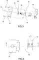
figure 3 shows a perspective view in separate parts of some components of a switch according to the present invention; -
figure 4 shows a side view of the components of the switch infigure 3 , in an assembled configuration; -
figure 5 shows a sectional view of the set of components infigure 4 , along the section plane V-V infigure 4 ; -
figures 6a-6b show sectional views of the enlarged detail VI infigure 5 ; -
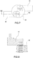
figure 7 shows a side view of the components of the switch infigure 3 , in an assembled configuration, according to a further embodiment of the present invention; -
figure 8 shows a sectional view of the set of components infigure 7 , along the section plane VIII-VIII infigure 7 ; -
figures 9a-9b show sectional views of the enlarged detail IX infigure 8 . - With reference to the above figures,
reference numeral 4 generally indicates a switch, preferably of the rotary type, comprising aswitch body 8 which defined aninner space 10 which rotatably houses ashaft 12, rotating about a rotation axis X-X, operatively connected to an external actuator device (not shown), such as a valve, an actuator, an electromechanical signalling device to an external system, said external device being arranged outside with respect to theinner space 10. -
Shaft 12 rotates about the rotation axis X-X according to the operation of the external device. - Preferably, but not in a binding manner,
body 8 is made of metal or externally coated with metal. - The shape, number of walls and geometrical dimensions of the
switch body 8 may be of any type and should in no way be considered limiting for the purposes of the present invention. -
Shaft 12 may be passing through abottom 18 of theswitch body 8 and may be supported by supports arranged internally and/or externally to theswitch body 8, in a known manner. - Shaft 12 may be associated to cams 20 for operating additional devices, such as electrical signalling devices of switches, inductive sensors, proximity sensors and the like. The type of devices listed above should be considered in a simplifying and non exhaustive manner.
- In other words,
shaft 12 rotates with the external device, such as a valve or an actuator, and by rotating, it performs the function of switch operating, for example by cams, a plurality of devices connected to switch 4. - In this way, according to the operation or operating condition of the external device, such as a valve or an actuator,
switch 4 can operate a plurality of devices; the timing betweenswitch 4 and the valve or actuator is ensured byshaft 12 which rotates integrally with the valve or actuator. -
Switch 4 further comprises acover 24, associated with saidswitch body 8; preferably,cover 28 is associated with theswitch body 8 on the side of anopen end 26 so as to close saidinner space 10, on a side opposite tobottom 18. -
Switch 4, comprising theswitch body 8,bottom 18 andcover 24, is generally hermetically sealed, so as to be anti-explosion, as better described hereafter. - Preferably,
cover 24 is made of metal or is externally coated with metal. - According to an embodiment,
cover 24 is provided with anindicator 28 rotatable about said rotation axis X-X, and with anindicator cover 30,indicator 28 being associated in rotation withshaft 12, for example by means of a stem, so as to allow a visual indication of the angular position and/or operating condition of therotary shaft 12, from the outside of the switch. - The shape, number of side walls and geometrical dimensions of
cover 24 may be of any type and should in no way be considered limiting for the purposes of the present invention. -
Indicator 28 may have any type of shape; preferably, it is axial-symmetric and has a disc shape. -
Indicator 28 shows the operating status of the external device, operatively connected to the shaft, such indications being shown with mechanical, chemical, electrochemical processes or by affixing labels. -
Switch 4 includes adistribution valve 32 arranged externally to saidinner space 10 of theswitch body 8. Thedistributor valve 32 can be of any type, shape, material and size and is a pneumatically operated valve. -
Switch 4 further comprises apneumatic connector 36 and at least one control means 40, such as a solenoid, operatively connected to thepneumatic connector 36. In other words, thedistribution valve 32 is operated by the control means, such assolenoid 40, by means of thepneumatic connector 36. - Both the
pneumatic connector 36 and the control means 40 are positioned in theinner space 10 of theswitch body 8. - The control means 40 is in turn operatively connected to the external device, and the
distribution valve 32 is operatively connected to the control means 40 by means of thepneumatic connector 36, so as to selectively operate thedistribution valve 32 itself. - The
pneumatic connector 36 defines at least oneconnection channel 44 placing thedistribution valve 32 in fluidic connection with the control means 40, wherein theconnection channel 44 crosses thepneumatic connector 36 which in turn crosses aside wall 48 of theswitch body 8. According to one embodiment, the connection channel is a cylindrical channel, having an extension axis Y-Y. - Advantageously, inside the
connection channel 44 at least one anti-explosion means 52 is inserted, positioned coaxially to theconnection channel 44 so as to reduce the throughcross-section 56 thereof by a predefined length of theconnection channel 44. - Advantageously, at the anti-explosion or dust-prevention means 52, the
through cross-section 56 is confined on an outer circular crown of theconnection channel 44, delimited between aninner side wall 60 of theconnection channel 44 and an externallateral wall 64 of the anti-explosion means 52. - In
figures 6b and9b , the fluid path, along said throughcross-section 56, is shown with arrow F said passage section - According to a possible embodiment (
figures 3-6 ), the anti-explosion means 52 comprises a metric nut or a metric screw 68, screwed onto a corresponding nut thread made on theinner side wall 60 of theconnection channel 44, so as to delimit a through cross-section having 56 having a helical pattern. - According to a further embodiment (
figures 7-9 ), the anti-explosion means 52 comprises a calibrated cylinder 72, positioned coaxially to saidconnection channel 44, so as to define a throughcross-section 56 in the shape of a circular crown. -
Switch 4 includes first mechanical connection means 76 between thedistribution valve 32 and thepneumatic connector 36, said first mechanical connection means 76 being inserted in thepneumatic connector 36 which in turn crosses theside wall 48 of theswitch body 8. - Such first mechanical connection means 76 thus have the function of fixing the
distribution valve 32 with thepneumatic connector 36. -
Switch 4 further comprises second mechanical connection means 84 between thedistribution valve 32 and theswitch body 8; the second mechanical connection means 84 perform the function of connecting thedistribution valve 32 to theswitch body 8 and, in particular, to theside wall 48 of theswitch body 8, in order to have a rigid connection between the two components and to ensure the pressure seal also by means of the sealing devices, such as sealing means orsealants 90. - For example, the first and/or second mechanical connection means 76, 84 of the
distribution valve 32 are threaded connection means which sealingly engage in theside wall 48 of theswitch body 8, so as to prevent the exit of gas and/or flames from theinner space 10 towards the outside. - According to an embodiment, between the
distribution valve 32 and the anti-explosion means 52 there are inserted air filtering means 88 and sealing means orsealants 90. - Said air filtering means 88 or sealing means 90 are inserted into the
connection channel 44. - For example, said air filtering means 88 or sealing means 90 comprise porous filters and/or 0-ring type gaskets.
- Advantageously, the
pneumatic connector 36 is of such a size as to ensure that the connection joint between theconnector 36 and thebody wall 48 does not permit the exit of the flame in the case of an explosion inside theinner space 10. By size of the pneumatic connector it is meant both its section and its length, the length being measured with respect to an axis parallel to said extension axis Y-Y, and the section being measured with respect to a section plane perpendicular to the same extension axis Y-Y. - The
pneumatic connector 36 is also provided with a sealinggasket 91 which allows the seal ofswitch 4 to the entrance of water or dust. - Said sealing
gasket 91 is for example housed in a groove 93 made on the outer surface of thepneumatic connector 36. - As can be appreciated from the description, the switch of the present invention allows overcoming the drawbacks of the prior art.
- Advantageously, the present invention allows obtaining a rapid assembly, inside the switch box, of the subassembly formed by the connection block, provided with the flame retardant joint, and of the control devices, such as the solenoid valves.
- Furthermore, the solution according to the invention is particularly compact.
- The distribution valve also acts as a locking element of the connection block via the respective screws; these also have the task of withstanding the internal pressure exerted on the block in the case of explosion inside the box.
- In this way, the structure of the box is particularly resistant in cases of explosion.
- As seen, the connection between the control devices, arranged inside the box, and the distribution valve, arranged outside the box, is anti-explosion and resistant to the entrance of dust and water inside
switch 4. - This type of connection is ensured by the presence of joints which always ensure a sufficient passage of air. Therefore, the risk of clogging of the filters, typical of the prior art solutions, is prevented and at the same time there is no risk of propagation of flames outside of the container box or entrance of dust or water.
- In fact, the path for the passage of air is always confined to the outer circular periphery of the connection conduits so as to oppose any propagations of said flame front.
- The presence of
seals - A man skilled in the art may make several changes and adjustments to the switches described above in order to meet specific and incidental needs, all falling within the scope of protection defined in the following claims.
Claims (16)
- Rotary switch (4) comprising- a switch body (8) which identifies an inner space (10) which rotatably houses a shaft (12) rotating around a rotation axis (X-X), operatively connected to an actuator device external to the switch (4), such as a valve or an actuator, characterised by- a distribution valve (32) positioned outside said inner space (10) of the switch body (8) and pneumatically connectable to said external actuator device,- a pneumatic connector (36) and at least one control means (40), such as a solenoid, operatively connected to the pneumatic connector (36),- the pneumatic connector (36) being at least partially positioned in the wall (48) of the switch body (8),- the control means (40) being positioned in the inner space (10) of the switch body (8),- the control means (40) being adapted to be operatively connected to an external control device, the distribution valve (32) being pneumatically connectable to the external actuator and operatively connected to the control means (40) by means of the pneumatic connector (36), so as to permit its selective operation by the control means (40), wherein- the pneumatic connector (36) defines at least one connection channel (44) placing the distribution valve (32) in fluidic connection with the control means (40), wherein the connection channel (44) crosses the pneumatic connector (36) which in turn crosses a side wall (48) of the switch body (8),- wherein inside the connection channel (44) at least one anti-explosion means (52) is inserted, positioned coaxially to the connection channel (44) so as to reduce the through cross-section (56) thereof by a predefined length of the connection channel (44),- wherein, at the anti-explosion means (52), the through cross-section (56) is confined on an outer circular crown of the connection channel (44), delimited between an inner side wall (60) of the connection channel (44)and an external lateral wall (64) of the anti-explosion means (52).
- Switch (4) according to claim 1, wherein said anti-explosion or dust-prevention means (52) comprises a metric nut or a metric screw (68), screwed onto a corresponding nut thread made on the inner side wall (60) of the connection channel (44), so as to delimit a through cross-section having (56) having a helical pattern.
- Switch (4) according to claim 1 or 2, wherein said anti-explosion or dust-prevention means (52) comprises a calibrated cylinder (72), positioned coaxially to said connection channel (44), so as to define a through cross-section (56) in the shape of a circular crown.
- Switch (4) according to claim 1, 2 or 3, wherein the switch (4) comprises first mechanical connection means (76) between the distribution valve (32) and the pneumatic connector (36), said first mechanical connection means (76) passing through a side wall (48) of the switch body (8).
- Switch (4) according to any of the previous claims, wherein the switch (4) comprises second mechanical connection means (84) between the distribution valve (32) and the switch body (8), the second mechanical connection means (84) have the function of connecting the distribution valve (32) to the switch body (8) and, in particular, to the side wall (48) of the switch body (8), so as to have a rigid connection between the two components.
- Switch (4) according to claim 4 or 5, wherein said first and/or second mechanical connection means (76, 84) of the distribution valve (32) are threaded connection means which sealingly engage in the side wall (48) of the switch body (8), so as to prevent the exit of gas and/or flames from the inner space (10) towards the outside of the switch body (8).
- Switch (4) according to claim 4, 5 or 6, wherein said first and/or second mechanical connection means (76, 84) of the distribution valve (32) are threaded connection means which sealingly engage in the side wall (48) of the switch body (8), so as to prevent the entrance of dust in the inner space (10) from outside the switch body (8).
- Switch (4) according to claim 5, 6 or 7, wherein said second mechanical connection means (84) of the distribution valve (32) are threaded connection means which sealingly engage in the pneumatic connector (36), so as to prevent the exit of gas and/or flames from the inner space (10) towards the outside of the switch body (8), and to prevent the entrance of dust in the inner space (10) from outside the switch body (8).
- Switch (4) according to any of the previous claims, wherein air filtering means (88) are inserted between the distribution valve (32) and the anti-explosion means (52).
- Switch (4) according to any of the previous claims, wherein, sealing means (90) are inserted between the distribution valve (32) and the anti-explosion means (52).
- Switch (4) according to claim 9 or 10, wherein said air filtering (88) or sealing (90) means are inserted inside the connection channel (44), in the pneumatic connector (36).
- Switch (4) according to any of the claims from 9 to 11, wherein said air filtering means (88) comprise porous filters and the sealing means (90) comprise 0-ring type gaskets.
- Switch (4) according to any of the previous claims, wherein sealing components (91) are placed between the pneumatic connector (36) and a side wall (48) of the switch body (8).
- Switch (4) according to claim 13, wherein said sealing elements (91) comprise 0-ring type gaskets.
- Switch (4) according to any of the previous claims, wherein the pneumatic connector (36) is of such a size as to ensure that the connection joint between the connector (36) and the body wall (48) does not permit the exit of the flame in the case of an explosion inside the inner space (10).
- Switch (4) according to any of the previous claims, comprising a cover (28), joined so as to close said switch body (8),fitted with an indicator (28) joined in rotation to said shaft (12), so as to permit a visual signalling of the angular position and/or operating condition of the rotating shaft (12), from outside the switch (4).
Applications Claiming Priority (2)
| Application Number | Priority Date | Filing Date | Title |
|---|---|---|---|
| IT000139A ITBS20130139A1 (en) | 2013-10-07 | 2013-10-07 | EXPLOSION-PROOF ROTARY SWITCH, EQUIPPED WITH VISUAL REPORTING MEANS AND MEANS OF CONTROL |
| PCT/IB2014/064315 WO2015052602A1 (en) | 2013-10-07 | 2014-09-08 | Anti-explosion rotary switch, provided with visual signalling means and control means |
Publications (2)
| Publication Number | Publication Date |
|---|---|
| EP3055598A1 EP3055598A1 (en) | 2016-08-17 |
| EP3055598B1 true EP3055598B1 (en) | 2017-11-15 |
Family
ID=49725198
Family Applications (1)
| Application Number | Title | Priority Date | Filing Date |
|---|---|---|---|
| EP14790326.4A Not-in-force EP3055598B1 (en) | 2013-10-07 | 2014-09-08 | Anti-explosion rotary switch, provided with visual signalling means and control means |
Country Status (11)
| Country | Link |
|---|---|
| US (1) | US9978546B2 (en) |
| EP (1) | EP3055598B1 (en) |
| JP (1) | JP6626439B2 (en) |
| KR (1) | KR20160081919A (en) |
| CN (1) | CN105980752B (en) |
| BR (1) | BR112016007628A2 (en) |
| ES (1) | ES2655861T3 (en) |
| IT (1) | ITBS20130139A1 (en) |
| NO (1) | NO3055598T3 (en) |
| SG (1) | SG11201602680SA (en) |
| WO (1) | WO2015052602A1 (en) |
Families Citing this family (1)
| Publication number | Priority date | Publication date | Assignee | Title |
|---|---|---|---|---|
| US11456142B2 (en) | 2018-12-26 | 2022-09-27 | Eaton Intelligent Power Limited | Hazardous location compliant circuit protection devices, systems and methods with safety lockout/tagout components |
Family Cites Families (9)
| Publication number | Priority date | Publication date | Assignee | Title |
|---|---|---|---|---|
| US3670274A (en) * | 1970-10-06 | 1972-06-13 | Skinner Precision Ind Inc | Explosion-proof valve operator |
| US4214133A (en) * | 1977-12-22 | 1980-07-22 | Rose John F | Rotary shaft position switch |
| DE4009978A1 (en) * | 1989-04-04 | 1990-10-11 | Hoerbiger Hydraulik | Control valve actuator system - incorporates sealed actuator pin to operate valve seal |
| JP2587321B2 (en) * | 1990-11-21 | 1997-03-05 | 山武ハネウエル株式会社 | Positioner |
| ITMI20041099A1 (en) * | 2004-05-31 | 2004-08-31 | Soldo S R L | SIGNAL ACTUATOR DEVICE FOR A POSITION ADJUSTMENT DRIVE |
| CN201093115Y (en) * | 2007-08-22 | 2008-07-30 | 天津百利二通机械有限公司 | Rotary switch type on-site control mechanism of valve electric device |
| US8375883B2 (en) * | 2007-12-12 | 2013-02-19 | Soldo S.R.L. Socio Unico | Rotary switch and relative assembly method |
| ES2617257T3 (en) * | 2011-09-20 | 2017-06-16 | Soldo S.R.L. Socio Unico | Switching box |
| ITUB20155510A1 (en) * | 2015-11-12 | 2017-05-12 | Soldo S R L Socio Unico | ROTARY SWITCH SUITABLE FOR USE IN ADVERSE ENVIRONMENTAL CONDITIONS |
-
2013
- 2013-10-07 IT IT000139A patent/ITBS20130139A1/en unknown
-
2014
- 2014-09-08 ES ES14790326.4T patent/ES2655861T3/en active Active
- 2014-09-08 US US15/027,959 patent/US9978546B2/en not_active Expired - Fee Related
- 2014-09-08 JP JP2016522035A patent/JP6626439B2/en not_active Expired - Fee Related
- 2014-09-08 SG SG11201602680SA patent/SG11201602680SA/en unknown
- 2014-09-08 KR KR1020167012120A patent/KR20160081919A/en not_active Ceased
- 2014-09-08 CN CN201480063017.XA patent/CN105980752B/en not_active Expired - Fee Related
- 2014-09-08 BR BR112016007628A patent/BR112016007628A2/en active Search and Examination
- 2014-09-08 WO PCT/IB2014/064315 patent/WO2015052602A1/en not_active Ceased
- 2014-09-08 NO NO14790326A patent/NO3055598T3/no unknown
- 2014-09-08 EP EP14790326.4A patent/EP3055598B1/en not_active Not-in-force
Non-Patent Citations (1)
| Title |
|---|
| None * |
Also Published As
| Publication number | Publication date |
|---|---|
| US20160240334A1 (en) | 2016-08-18 |
| US9978546B2 (en) | 2018-05-22 |
| SG11201602680SA (en) | 2016-05-30 |
| EP3055598A1 (en) | 2016-08-17 |
| ITBS20130139A1 (en) | 2015-04-08 |
| JP2017500495A (en) | 2017-01-05 |
| ES2655861T3 (en) | 2018-02-21 |
| CN105980752A (en) | 2016-09-28 |
| CN105980752B (en) | 2018-10-19 |
| BR112016007628A2 (en) | 2017-08-01 |
| WO2015052602A1 (en) | 2015-04-16 |
| KR20160081919A (en) | 2016-07-08 |
| JP6626439B2 (en) | 2019-12-25 |
| NO3055598T3 (en) | 2018-04-14 |
Similar Documents
| Publication | Publication Date | Title |
|---|---|---|
| KR20140100867A (en) | Gate valve | |
| JP5085641B2 (en) | Fluid powered double piston actuator with efficient fluid movement and method of implementation | |
| JP5745591B2 (en) | Occlusion and discharge valve assembly | |
| AU2008355012A1 (en) | Valve combination for regulating the flow rate or differential pressure | |
| JP6010106B2 (en) | Diaphragm control valve with universal diaphragm mounting position | |
| US9978546B2 (en) | Anti-explosion rotary switch, provided with visual signaling means and control means | |
| US20150034183A1 (en) | Externally adjustable magnetic target setting | |
| TR201810699T4 (en) | Balancing valve. | |
| EP2551566B1 (en) | Rotary valve and rotary valve seal | |
| EP2573439B1 (en) | Switch box | |
| CN103982668A (en) | Gate valve | |
| US20100090139A1 (en) | Intercepting Valve | |
| US20060174949A1 (en) | Diaphragm valve | |
| KR0138535Y1 (en) | Ball valve | |
| EP1798458B1 (en) | Diaphragm valve for compressed or liquefied gases | |
| EP3458753B1 (en) | Self contained gate valve column loading prevention mechanism | |
| JP2017500495A5 (en) | ||
| US6318409B1 (en) | System for assembling at least two pressurized fluid control members | |
| CN216112430U (en) | Pilot valve for pilot-operated pneumatic valve | |
| CN115750904B (en) | Sealing rocker valve and gas generator | |
| JP4599813B2 (en) | Fluid controller | |
| KR20240175147A (en) | Sealing Structure For Filter Assembly Having Plastic Housing | |
| KR20110026191A (en) | Valve device | |
| CN201973350U (en) | valve leak stop | |
| ITMI991729A1 (en) | SAFETY VALVE ESPECIALLY FOR FIRE EXTINGUISHING VALVES AND SIMILAR |
Legal Events
| Date | Code | Title | Description |
|---|---|---|---|
| PUAI | Public reference made under article 153(3) epc to a published international application that has entered the european phase |
Free format text: ORIGINAL CODE: 0009012 |
|
| 17P | Request for examination filed |
Effective date: 20160506 |
|
| AK | Designated contracting states |
Kind code of ref document: A1 Designated state(s): AL AT BE BG CH CY CZ DE DK EE ES FI FR GB GR HR HU IE IS IT LI LT LU LV MC MK MT NL NO PL PT RO RS SE SI SK SM TR |
|
| AX | Request for extension of the european patent |
Extension state: BA ME |
|
| DAX | Request for extension of the european patent (deleted) | ||
| GRAP | Despatch of communication of intention to grant a patent |
Free format text: ORIGINAL CODE: EPIDOSNIGR1 |
|
| STAA | Information on the status of an ep patent application or granted ep patent |
Free format text: STATUS: GRANT OF PATENT IS INTENDED |
|
| INTG | Intention to grant announced |
Effective date: 20170523 |
|
| GRAS | Grant fee paid |
Free format text: ORIGINAL CODE: EPIDOSNIGR3 |
|
| GRAA | (expected) grant |
Free format text: ORIGINAL CODE: 0009210 |
|
| STAA | Information on the status of an ep patent application or granted ep patent |
Free format text: STATUS: THE PATENT HAS BEEN GRANTED |
|
| AK | Designated contracting states |
Kind code of ref document: B1 Designated state(s): AL AT BE BG CH CY CZ DE DK EE ES FI FR GB GR HR HU IE IS IT LI LT LU LV MC MK MT NL NO PL PT RO RS SE SI SK SM TR |
|
| REG | Reference to a national code |
Ref country code: CH Ref legal event code: EP Ref country code: GB Ref legal event code: FG4D Ref country code: AT Ref legal event code: REF Ref document number: 946629 Country of ref document: AT Kind code of ref document: T Effective date: 20171115 |
|
| REG | Reference to a national code |
Ref country code: IE Ref legal event code: FG4D |
|
| REG | Reference to a national code |
Ref country code: DE Ref legal event code: R096 Ref document number: 602014017335 Country of ref document: DE |
|
| REG | Reference to a national code |
Ref country code: ES Ref legal event code: FG2A Ref document number: 2655861 Country of ref document: ES Kind code of ref document: T3 Effective date: 20180221 |
|
| REG | Reference to a national code |
Ref country code: NL Ref legal event code: MP Effective date: 20171115 |
|
| REG | Reference to a national code |
Ref country code: LT Ref legal event code: MG4D |
|
| REG | Reference to a national code |
Ref country code: NO Ref legal event code: T2 Effective date: 20171115 |
|
| REG | Reference to a national code |
Ref country code: AT Ref legal event code: MK05 Ref document number: 946629 Country of ref document: AT Kind code of ref document: T Effective date: 20171115 |
|
| PG25 | Lapsed in a contracting state [announced via postgrant information from national office to epo] |
Ref country code: FI Free format text: LAPSE BECAUSE OF FAILURE TO SUBMIT A TRANSLATION OF THE DESCRIPTION OR TO PAY THE FEE WITHIN THE PRESCRIBED TIME-LIMIT Effective date: 20171115 Ref country code: NL Free format text: LAPSE BECAUSE OF FAILURE TO SUBMIT A TRANSLATION OF THE DESCRIPTION OR TO PAY THE FEE WITHIN THE PRESCRIBED TIME-LIMIT Effective date: 20171115 Ref country code: LT Free format text: LAPSE BECAUSE OF FAILURE TO SUBMIT A TRANSLATION OF THE DESCRIPTION OR TO PAY THE FEE WITHIN THE PRESCRIBED TIME-LIMIT Effective date: 20171115 Ref country code: SE Free format text: LAPSE BECAUSE OF FAILURE TO SUBMIT A TRANSLATION OF THE DESCRIPTION OR TO PAY THE FEE WITHIN THE PRESCRIBED TIME-LIMIT Effective date: 20171115 |
|
| PG25 | Lapsed in a contracting state [announced via postgrant information from national office to epo] |
Ref country code: GR Free format text: LAPSE BECAUSE OF FAILURE TO SUBMIT A TRANSLATION OF THE DESCRIPTION OR TO PAY THE FEE WITHIN THE PRESCRIBED TIME-LIMIT Effective date: 20180216 Ref country code: HR Free format text: LAPSE BECAUSE OF FAILURE TO SUBMIT A TRANSLATION OF THE DESCRIPTION OR TO PAY THE FEE WITHIN THE PRESCRIBED TIME-LIMIT Effective date: 20171115 Ref country code: LV Free format text: LAPSE BECAUSE OF FAILURE TO SUBMIT A TRANSLATION OF THE DESCRIPTION OR TO PAY THE FEE WITHIN THE PRESCRIBED TIME-LIMIT Effective date: 20171115 Ref country code: RS Free format text: LAPSE BECAUSE OF FAILURE TO SUBMIT A TRANSLATION OF THE DESCRIPTION OR TO PAY THE FEE WITHIN THE PRESCRIBED TIME-LIMIT Effective date: 20171115 Ref country code: BG Free format text: LAPSE BECAUSE OF FAILURE TO SUBMIT A TRANSLATION OF THE DESCRIPTION OR TO PAY THE FEE WITHIN THE PRESCRIBED TIME-LIMIT Effective date: 20180215 Ref country code: AT Free format text: LAPSE BECAUSE OF FAILURE TO SUBMIT A TRANSLATION OF THE DESCRIPTION OR TO PAY THE FEE WITHIN THE PRESCRIBED TIME-LIMIT Effective date: 20171115 |
|
| PG25 | Lapsed in a contracting state [announced via postgrant information from national office to epo] |
Ref country code: SK Free format text: LAPSE BECAUSE OF FAILURE TO SUBMIT A TRANSLATION OF THE DESCRIPTION OR TO PAY THE FEE WITHIN THE PRESCRIBED TIME-LIMIT Effective date: 20171115 Ref country code: CY Free format text: LAPSE BECAUSE OF FAILURE TO SUBMIT A TRANSLATION OF THE DESCRIPTION OR TO PAY THE FEE WITHIN THE PRESCRIBED TIME-LIMIT Effective date: 20171115 Ref country code: EE Free format text: LAPSE BECAUSE OF FAILURE TO SUBMIT A TRANSLATION OF THE DESCRIPTION OR TO PAY THE FEE WITHIN THE PRESCRIBED TIME-LIMIT Effective date: 20171115 Ref country code: DK Free format text: LAPSE BECAUSE OF FAILURE TO SUBMIT A TRANSLATION OF THE DESCRIPTION OR TO PAY THE FEE WITHIN THE PRESCRIBED TIME-LIMIT Effective date: 20171115 Ref country code: CZ Free format text: LAPSE BECAUSE OF FAILURE TO SUBMIT A TRANSLATION OF THE DESCRIPTION OR TO PAY THE FEE WITHIN THE PRESCRIBED TIME-LIMIT Effective date: 20171115 |
|
| REG | Reference to a national code |
Ref country code: DE Ref legal event code: R097 Ref document number: 602014017335 Country of ref document: DE |
|
| PG25 | Lapsed in a contracting state [announced via postgrant information from national office to epo] |
Ref country code: RO Free format text: LAPSE BECAUSE OF FAILURE TO SUBMIT A TRANSLATION OF THE DESCRIPTION OR TO PAY THE FEE WITHIN THE PRESCRIBED TIME-LIMIT Effective date: 20171115 Ref country code: SM Free format text: LAPSE BECAUSE OF FAILURE TO SUBMIT A TRANSLATION OF THE DESCRIPTION OR TO PAY THE FEE WITHIN THE PRESCRIBED TIME-LIMIT Effective date: 20171115 Ref country code: IT Free format text: LAPSE BECAUSE OF FAILURE TO SUBMIT A TRANSLATION OF THE DESCRIPTION OR TO PAY THE FEE WITHIN THE PRESCRIBED TIME-LIMIT Effective date: 20171115 Ref country code: PL Free format text: LAPSE BECAUSE OF FAILURE TO SUBMIT A TRANSLATION OF THE DESCRIPTION OR TO PAY THE FEE WITHIN THE PRESCRIBED TIME-LIMIT Effective date: 20171115 |
|
| PLBE | No opposition filed within time limit |
Free format text: ORIGINAL CODE: 0009261 |
|
| STAA | Information on the status of an ep patent application or granted ep patent |
Free format text: STATUS: NO OPPOSITION FILED WITHIN TIME LIMIT |
|
| 26N | No opposition filed |
Effective date: 20180817 |
|
| PG25 | Lapsed in a contracting state [announced via postgrant information from national office to epo] |
Ref country code: SI Free format text: LAPSE BECAUSE OF FAILURE TO SUBMIT A TRANSLATION OF THE DESCRIPTION OR TO PAY THE FEE WITHIN THE PRESCRIBED TIME-LIMIT Effective date: 20171115 |
|
| REG | Reference to a national code |
Ref country code: ES Ref legal event code: PC2A Owner name: ROTORK INSTRUMENTS ITALY S.R.L. Effective date: 20190402 |
|
| PG25 | Lapsed in a contracting state [announced via postgrant information from national office to epo] |
Ref country code: MC Free format text: LAPSE BECAUSE OF FAILURE TO SUBMIT A TRANSLATION OF THE DESCRIPTION OR TO PAY THE FEE WITHIN THE PRESCRIBED TIME-LIMIT Effective date: 20171115 |
|
| REG | Reference to a national code |
Ref country code: CH Ref legal event code: PL |
|
| REG | Reference to a national code |
Ref country code: NO Ref legal event code: CHAD Owner name: ROTORK INSTRUMENTS ITALY S.R.L, IT |
|
| REG | Reference to a national code |
Ref country code: BE Ref legal event code: MM Effective date: 20180930 |
|
| REG | Reference to a national code |
Ref country code: IE Ref legal event code: MM4A |
|
| PG25 | Lapsed in a contracting state [announced via postgrant information from national office to epo] |
Ref country code: LU Free format text: LAPSE BECAUSE OF NON-PAYMENT OF DUE FEES Effective date: 20180908 |
|
| REG | Reference to a national code |
Ref country code: DE Ref legal event code: R082 Ref document number: 602014017335 Country of ref document: DE Representative=s name: ZEITLER VOLPERT KANDLBINDER PATENT- UND RECHTS, DE Ref country code: DE Ref legal event code: R081 Ref document number: 602014017335 Country of ref document: DE Owner name: ROTORK INSTRUMENTS ITALY S.R.L., IT Free format text: FORMER OWNER: SOLDO S.R.L. SOCIO UNICO, DESENZANO DEL GARDA, BRESCIA, IT Ref country code: DE Ref legal event code: R082 Ref document number: 602014017335 Country of ref document: DE Representative=s name: ZEITLER VOLPERT KANDLBINDER PATENTANWAELTE PAR, DE |
|
| PG25 | Lapsed in a contracting state [announced via postgrant information from national office to epo] |
Ref country code: IE Free format text: LAPSE BECAUSE OF NON-PAYMENT OF DUE FEES Effective date: 20180908 |
|
| PG25 | Lapsed in a contracting state [announced via postgrant information from national office to epo] |
Ref country code: LI Free format text: LAPSE BECAUSE OF NON-PAYMENT OF DUE FEES Effective date: 20180930 Ref country code: FR Free format text: LAPSE BECAUSE OF NON-PAYMENT OF DUE FEES Effective date: 20180930 Ref country code: BE Free format text: LAPSE BECAUSE OF NON-PAYMENT OF DUE FEES Effective date: 20180930 Ref country code: CH Free format text: LAPSE BECAUSE OF NON-PAYMENT OF DUE FEES Effective date: 20180930 |
|
| PGFP | Annual fee paid to national office [announced via postgrant information from national office to epo] |
Ref country code: NO Payment date: 20190905 Year of fee payment: 6 Ref country code: DE Payment date: 20190909 Year of fee payment: 6 |
|
| PGFP | Annual fee paid to national office [announced via postgrant information from national office to epo] |
Ref country code: GB Payment date: 20190906 Year of fee payment: 6 |
|
| PG25 | Lapsed in a contracting state [announced via postgrant information from national office to epo] |
Ref country code: MT Free format text: LAPSE BECAUSE OF NON-PAYMENT OF DUE FEES Effective date: 20180908 |
|
| PGFP | Annual fee paid to national office [announced via postgrant information from national office to epo] |
Ref country code: ES Payment date: 20191017 Year of fee payment: 6 |
|
| PG25 | Lapsed in a contracting state [announced via postgrant information from national office to epo] |
Ref country code: TR Free format text: LAPSE BECAUSE OF FAILURE TO SUBMIT A TRANSLATION OF THE DESCRIPTION OR TO PAY THE FEE WITHIN THE PRESCRIBED TIME-LIMIT Effective date: 20171115 |
|
| PG25 | Lapsed in a contracting state [announced via postgrant information from national office to epo] |
Ref country code: PT Free format text: LAPSE BECAUSE OF FAILURE TO SUBMIT A TRANSLATION OF THE DESCRIPTION OR TO PAY THE FEE WITHIN THE PRESCRIBED TIME-LIMIT Effective date: 20171115 |
|
| PG25 | Lapsed in a contracting state [announced via postgrant information from national office to epo] |
Ref country code: HU Free format text: LAPSE BECAUSE OF FAILURE TO SUBMIT A TRANSLATION OF THE DESCRIPTION OR TO PAY THE FEE WITHIN THE PRESCRIBED TIME-LIMIT; INVALID AB INITIO Effective date: 20140908 Ref country code: MK Free format text: LAPSE BECAUSE OF NON-PAYMENT OF DUE FEES Effective date: 20171115 |
|
| PG25 | Lapsed in a contracting state [announced via postgrant information from national office to epo] |
Ref country code: AL Free format text: LAPSE BECAUSE OF FAILURE TO SUBMIT A TRANSLATION OF THE DESCRIPTION OR TO PAY THE FEE WITHIN THE PRESCRIBED TIME-LIMIT Effective date: 20171115 Ref country code: IS Free format text: LAPSE BECAUSE OF FAILURE TO SUBMIT A TRANSLATION OF THE DESCRIPTION OR TO PAY THE FEE WITHIN THE PRESCRIBED TIME-LIMIT Effective date: 20180315 |
|
| REG | Reference to a national code |
Ref country code: DE Ref legal event code: R119 Ref document number: 602014017335 Country of ref document: DE |
|
| REG | Reference to a national code |
Ref country code: NO Ref legal event code: MMEP |
|
| GBPC | Gb: european patent ceased through non-payment of renewal fee |
Effective date: 20200908 |
|
| PG25 | Lapsed in a contracting state [announced via postgrant information from national office to epo] |
Ref country code: NO Free format text: LAPSE BECAUSE OF NON-PAYMENT OF DUE FEES Effective date: 20200930 Ref country code: DE Free format text: LAPSE BECAUSE OF NON-PAYMENT OF DUE FEES Effective date: 20210401 |
|
| PG25 | Lapsed in a contracting state [announced via postgrant information from national office to epo] |
Ref country code: GB Free format text: LAPSE BECAUSE OF NON-PAYMENT OF DUE FEES Effective date: 20200908 |
|
| REG | Reference to a national code |
Ref country code: ES Ref legal event code: FD2A Effective date: 20220114 |
|
| PG25 | Lapsed in a contracting state [announced via postgrant information from national office to epo] |
Ref country code: ES Free format text: LAPSE BECAUSE OF NON-PAYMENT OF DUE FEES Effective date: 20200909 |