EP3055559B1 - Lightning current transfer system and wind turbine using the lightning current transfer system - Google Patents
Lightning current transfer system and wind turbine using the lightning current transfer system Download PDFInfo
- Publication number
- EP3055559B1 EP3055559B1 EP14789151.9A EP14789151A EP3055559B1 EP 3055559 B1 EP3055559 B1 EP 3055559B1 EP 14789151 A EP14789151 A EP 14789151A EP 3055559 B1 EP3055559 B1 EP 3055559B1
- Authority
- EP
- European Patent Office
- Prior art keywords
- contact
- lightning
- wind turbine
- nacelle
- turbine according
- Prior art date
- Legal status (The legal status is an assumption and is not a legal conclusion. Google has not performed a legal analysis and makes no representation as to the accuracy of the status listed.)
- Active
Links
Images



Classifications
-
- F—MECHANICAL ENGINEERING; LIGHTING; HEATING; WEAPONS; BLASTING
- F03—MACHINES OR ENGINES FOR LIQUIDS; WIND, SPRING, OR WEIGHT MOTORS; PRODUCING MECHANICAL POWER OR A REACTIVE PROPULSIVE THRUST, NOT OTHERWISE PROVIDED FOR
- F03D—WIND MOTORS
- F03D80/00—Details, components or accessories not provided for in groups F03D1/00 - F03D17/00
- F03D80/30—Lightning protection
-
- F—MECHANICAL ENGINEERING; LIGHTING; HEATING; WEAPONS; BLASTING
- F03—MACHINES OR ENGINES FOR LIQUIDS; WIND, SPRING, OR WEIGHT MOTORS; PRODUCING MECHANICAL POWER OR A REACTIVE PROPULSIVE THRUST, NOT OTHERWISE PROVIDED FOR
- F03D—WIND MOTORS
- F03D1/00—Wind motors with rotation axis substantially parallel to the air flow entering the rotor
- F03D1/06—Rotors
- F03D1/065—Rotors characterised by their construction elements
-
- F—MECHANICAL ENGINEERING; LIGHTING; HEATING; WEAPONS; BLASTING
- F03—MACHINES OR ENGINES FOR LIQUIDS; WIND, SPRING, OR WEIGHT MOTORS; PRODUCING MECHANICAL POWER OR A REACTIVE PROPULSIVE THRUST, NOT OTHERWISE PROVIDED FOR
- F03D—WIND MOTORS
- F03D80/00—Details, components or accessories not provided for in groups F03D1/00 - F03D17/00
- F03D80/80—Arrangement of components within nacelles or towers
-
- F—MECHANICAL ENGINEERING; LIGHTING; HEATING; WEAPONS; BLASTING
- F03—MACHINES OR ENGINES FOR LIQUIDS; WIND, SPRING, OR WEIGHT MOTORS; PRODUCING MECHANICAL POWER OR A REACTIVE PROPULSIVE THRUST, NOT OTHERWISE PROVIDED FOR
- F03D—WIND MOTORS
- F03D9/00—Adaptations of wind motors for special use; Combinations of wind motors with apparatus driven thereby; Wind motors specially adapted for installation in particular locations
- F03D9/20—Wind motors characterised by the driven apparatus
- F03D9/25—Wind motors characterised by the driven apparatus the apparatus being an electrical generator
-
- F—MECHANICAL ENGINEERING; LIGHTING; HEATING; WEAPONS; BLASTING
- F05—INDEXING SCHEMES RELATING TO ENGINES OR PUMPS IN VARIOUS SUBCLASSES OF CLASSES F01-F04
- F05B—INDEXING SCHEME RELATING TO WIND, SPRING, WEIGHT, INERTIA OR LIKE MOTORS, TO MACHINES OR ENGINES FOR LIQUIDS COVERED BY SUBCLASSES F03B, F03D AND F03G
- F05B2240/00—Components
- F05B2240/20—Rotors
- F05B2240/21—Rotors for wind turbines
-
- Y—GENERAL TAGGING OF NEW TECHNOLOGICAL DEVELOPMENTS; GENERAL TAGGING OF CROSS-SECTIONAL TECHNOLOGIES SPANNING OVER SEVERAL SECTIONS OF THE IPC; TECHNICAL SUBJECTS COVERED BY FORMER USPC CROSS-REFERENCE ART COLLECTIONS [XRACs] AND DIGESTS
- Y02—TECHNOLOGIES OR APPLICATIONS FOR MITIGATION OR ADAPTATION AGAINST CLIMATE CHANGE
- Y02E—REDUCTION OF GREENHOUSE GAS [GHG] EMISSIONS, RELATED TO ENERGY GENERATION, TRANSMISSION OR DISTRIBUTION
- Y02E10/00—Energy generation through renewable energy sources
- Y02E10/70—Wind energy
- Y02E10/72—Wind turbines with rotation axis in wind direction
Definitions
- the invention relates to a lightning current transfer system adapted for usage in a wind turbine having a hub rotatably supported relative to a generator in a nacelle of the wind turbine and a plurality of blades pivotably connected with the hub.
- the invention also relates to a wind turbine in which the lightning current transfer system is implemented.
- DE4445899 describes a lightning protection system for a wind turbine where there is a path to discharge lightning currents between the blades and ground.
- DE102004010104 describes a wind turbine with a lightning protection system where lightning current is discharged via a roller and a ring.
- JP 05/060053A suggests a lightning protection system which guides the lightning energy from the hub to the nacelle through a slip ring device so as to avoid a lightning discharge path through the shaft bearings and the generators.
- This slip ring device consists of a disk which is mounted at the hub and which rotates with the hub. Carbon brushes mounted at the nacelle establish an electrically conductive path between the hub and the nacelle.
- FIG. 1 shows a wind turbine W with a nacelle 3 containing the generator (not shown) sitting on the wind turbine tower 4.
- the blades 1 supported by the hub 2 are connected through a generator shaft with the turbine generators in the nacelle 3.
- a blade lightning protection system 5 is provided in the form of a down conductor with thick conductive cables guiding the lightning power through the blades to the root of the blades 1. From there, the lightning current is transferred via the hub 2, the nacelle 3, and the tower 4 into ground G.
- Figures 2A and 2B show a more detailed view of the encircled section I in figure 1 .
- reference numeral 1 designates a blade
- numeral 2 designates the hub
- numeral 2A designates the spinner (the cover/housing of the hub)
- numeral 3 designates the nacelle
- numeral 3A designates the front plate of the nacelle
- reference numeral 6 designates the generator shaft which connects the hub 2 with the generator (not shown) in the nacelle 3.
- the lightning current transfer unit comprises a blade band 1A that is mounted at the root of the blade 1 and which is connected with the cables of the blade lightning protection system 5.
- the LCTU comprises a lightning ring 3B which is mounted at the nacelle front plate 3A.
- the hub 2 is relatively small compared to the nacelle 3 so that the blade band 1A and the nacelle lightning ring 3B are positioned to face each other. That is, the diameter D1 of the hub 2 is smaller than the diameter D2 of the nacelle 3 so that the blade band 1A can rotate inside of the nacelle perimeter dimensions D2.
- This dimensional relationship allows the positioning of a compact connecting device 7 which electrically connects the blade band 1A which is rotatable around a blade axis 9, and the nacelle lightning ring 3B which rotates relative to the connecting device 7 around the hub axis 8.
- the hub 2 and the connecting device 7 are collectively enclosed by a fibre glass cover to which it is referred as the spinner 2A.
- the connecting device 7 in figure 2A comprises a bracket 7D, to which one end of two fibre glass profiles 7B and 7C are mounted. At the other ends of the fibre glass profiles 7B and 7C, contact elements 7A and 7F are mounted respectively. A cable 7E connects the contact elements 7A and 7F. It has to be noted that figure 2A shows a small gap between contact elements 7A/7F and blade band 1A and lightning ring 3B, respectively, for illustration purposes. In operation, these contacts are sliding contacts.
- FIG. 3 A detailed view of the connecting device 7 is given in figure 3 which again shows the mounting bracket 7D, the glass fibre profiles 7C and 7B, the contact elements 7A and 7F and the cable 7E that electrically connects the contact elements 7A and 7F. Due to the elasticity and a pretension, the contact elements 7A and 7F are forced against the blade band and the lightning ring, to establish a point of low impedance between the blade band 1A and the lightning ring 3B.
- FIG. 2B shows a front view of figure 2A along axis 8 and illustrates the arrangement of the connecting devices 7 with regard to three blades 1.
- Each blade 1 is provided with a blade band 1A and each blade band is contacted with a respective connecting device 7 so that three connecting devices are necessary.
- Each connecting device 7 is also in contact with the lightning ring 3B illustrated in figure 2B as a dashed line. The contour of the lightning ring 3B is within the perimeter of the spinner 2A.
- FIG 4 A simplified 3-dimensional illustration of the hub 2 and the spinner 2A is shown in figure 4 .
- the spinner 2A has four openings, wherein the openings 2A-1, 2A-2 and 2A-3 are intended for feeding through the three blades and the fourth opening 2A-4 is used to allow a connection of the hub 2 with the generator shaft 6.
- the hub 2 includes four flanges 2-1, 2-2, 2-3 and 2-4 wherein the flanges 2-1, 2-2 and 2-3 are intended to mount a respective blade and flange 2-4 is intended to mount the generator shaft.
- Reference numerals 7-1, 7-2 and 7-3 symbolize three connecting devices as illustrated in figure 3 .
- the spinner opening 2A-4 is larger than the other openings in order to allow a connection of the connecting devices 7-1, 7-2 and 7-3 with the lightning ring at the nacelle through opening 2A-4.
- Figure 4 illustrates three connecting devices 7-1, 7-2 and 7-3, one for each blade 1.
- the lightning current transfer system of the present invention basically splits the integral connecting device of the state-of-the-art as described with reference to figure 3 into two separate contact devices which also allow an increase of the respect distance (separation distance) to sensitive parts like bearings and generator parts.
- the lightning ring can be mounted to the spinner and the second contact device are mountable to the nacelle which means that a plurality of second contact devices can be used on the nacelle side so that lightning current can be distributed over several contact points which reduces the current magnitude in one contact so that wear can also be reduced.
- This also adds redundancy and safety to the nacelle side lightning current transfer system in comparison to the prior art according to figures 2-4 .
- current flows only through one contact point into the nacelle and increases therefore load and wear of the contact device in a lightning current transfer system of the prior art.
- the blade band and the first contact device are configured to be mounted outside the spinner and the connecting device for connecting the first contact device with the lightning ring is configured to be mounted inside the spinner.
- This configuration allows on one hand larger respect distances (separation distances) between the first contact device/connecting device and bearings or other sensitive parts.
- connecting cables (connecting device) between the first contact device and the lightning ring can be made shorter so as to reduce the impedance between these points.
- the first contact device of the lightning current transfer system comprises a first mounting element mountable to the spinner, a first elastic non-conducting profile mounted to the first mounting element and a first contact element mounted at the first elastic non-conducting profile, wherein the first contact device is configured so that the first contact element faces the blade band and the first elastic non-conducting profile pushes the first contact element against the blade band.
- the first contact element has the advantage that the first contact element and the first elastic non-conducting profile of well-established preexisting lightning current transfer system like that illustrated in figures 2a and 3 can be reused.
- the first mounting element is designed to serve as a combination of a bracket (fixture for the first elastic non-conducting profile) and a cover which protects the first contact device against the environment because the first mounting element is mounted outside the spinner.
- the first contact element comprises a conductive rod and a sliding element, wherein the conductive rod extends through a hole of the sliding element so that an end surface of the conductive rod and a surface of the sliding element collectively form a contact area for slidingly contacting the blade band.
- contact elements of established lightning current transfer units can be implemented in this invention, saving manufacturing costs.
- the sliding element may be provided with a chamfered edge. This also improves ice sliding ability in case that icing occurs.
- the sliding area of the sliding element may have the shape of a hexagon with an edge of the hexagon in a moving direction of the sliding element so as to reduce friction in a sliding direction, in particular in case of a contaminated blade band surface.
- the sliding element may be made of Nylatron.
- the second contact device comprises a second mounting element one end thereof being mountable to a front plate of the nacelle so that the second mounting element protrudes therefrom, a second elastic non-conducting profile mounted at one end to another end of the second mounting element, an extension bracket mounted at the second elastic non-conducting profile, and a second contact element mounted at the extension bracket, wherein the second contact device is configured so that the contact element may extend through a hole in a nacelle front cover so as to face the lightning ring mounted at the spinner, and the second elastic non-conducting profile pushes the second contact element against the lightning ring.
- the second contact device, the elastic non-conducting profile and the second contact element of existing well-established lightning current transfer units can be used.
- the first elastic non-conducting profile may have the same structure as the second elastic non-conducting profile and the first contact element may have the same structure as the second contact element so that the respective elements are interchangeable on one hand and can also be used for older well-established lightning current transfer systems like that illustrated in figures 2a and 3 .
- the structure of the second contact device is configured to be mounted inside of the nacelle cover so that the second contact element can protrude through a small hole in the nacelle front cover to establish an electric contact with the lightning ring at the spinner.
- bending forces of the pre-tensed second elastic non-conducting profile ensure that the contact element is pressed against the lightning ring for making a low impedance contact.
- At least two second contact devices and more preferably, four second contact devices are used in a nacelle.
- the first mounting element comprises a fibre glass console acting as a fastening bracket for the first elastic non-conducting profile and a cover for protection of the first contact element.
- the contact element As the first contact device is mounted outside the spinner, the contact element is exposed to environment influences. The construction of the first contact device allows a protection of the contact element from environmental conditions.
- the second mounting element is a stainless steel bracket bridging the distance between the mechanically robust nacelle front plate and the nacelle front cover.
- the bracket can also be used as a tread for service personnel.
- the first elastic non-conducting profile and a second elastic non-conducting profile are fibre glass profiles.
- Fibre glass is a very robust, elastic and non-conductive material which can provide and transmit bending forces so as to establish a safe electrical contact between the contact elements on one side and the blade band and/or the lightning ring on the other side.
- the nacelle includes an inspection hatch in the nacelle front plate cover for inspecting the lightning ring.
- service can be provided in-situ.
- This invention has been made in order to provide a lightning current transfer system which can be used for wind turbines which are larger than the previous wind turbine constructions.
- the blades and the hub are increased in size so that the part of the lightning current transfer unit which is responsible for collecting the lightning current from the root of the blade rotates with the hub beyond the perimeter of the nacelle.
- this invention has been made in order to allow at least partially the usage of lightning current transfer units according to the state-of-the-art.
- all parts of the lightning current transfer unit of this invention shall be exchangeable in-situ and shall also reduce wear due to the lightning current.
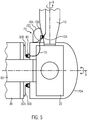
- FIG. 5 gives an overview of the lightning current transfer system according to the present invention.
- reference numeral 20 designates a hub
- reference numeral 10 designates a blade
- reference numeral 60 designates a shaft which connects the hub 20 with a generator (not shown) within the nacelle 30
- reference numeral 20A designates a spinner (aerodynamic housing of the hub 20).
- Figure 5 illustrates that the hub 20 is directly connected with the shaft 60 which in turn may be directly connected with the generator so as to implement a direct drive system.
- This invention is, however not restricted to such configurations.
- the gearbox may be directly mounted to the hub or may be interposed between a low speed shaft from the hub and a high speed shaft from the generator. Therefore, in more general terms, the hub is rotatably supported relative to the generator.
- the lightning current transfer system includes the blade band 10A, the lightning ring 80, the blade part contact device 70 (also referred to as a first contact device 70) and nacelle side contact device 30B (also referred to as a second contact device 30B).
- Blade part contact device 70 includes the blade part sliding contact 70B (also referred to as first contact element 70B), a nonconductive elastic glass fibre arm 70C (also referred to as first non-conductive elastic glass fibre profile 70C) and a first mounting element 70A which fixes the glass fibre profile 70C to the spinner 20A and protects at the same time the sliding contact 70B that is mounted at the glass fibre arm 70C against environment.
- An electrical connection 75 inside the spinner 20A connects the sliding contact 70B with the lightning ring 80 which is mounted at the back side of the spinner 20A so as to face sliding contacts (also referred to as second contact element) of the nacelle contact device 30B (second contact device 30B).
- Rotation axes 8 and 9 indicate the same rotating capabilities of the spinner/hub and the blade are as described in figure 2A .
- figure 5 shows a small gap between contact elements 70B/30B and blade band 10A and lightning ring 80, respectively, for illustrative purposes. In operation, these contacts are sliding contacts and no gaps are visible.
- the lightning current transfer system is exemplarily illustrated in form of sliding contacts that provide a low impedance connection.
- the term "low impedance” is intended to describe an impedance for a lightning current transfer path that is lower than alternative lightning current transfer paths, so that the lightning current transfer can be controlled.
- the low impedance connection is provided with sliding contacts. This invention is, however, not restricted to sliding contacts.
- the low impedance contacts may also be implemented as a spark gap-that is the electrical connection between the blade band 10A and the first contact element may a spark gap and/or the electrical connection between the lightning ring 80 and the second contact device 30B may be a spark gap, rather than sliding contacts.
- a contact for a lightning current transfer has to be distinguished from a low energy (low voltage) electrical contact.
- the claimed contacts for lightning current transfer have to be electrically conductive for potential differences above several thousand volts due to the high voltages of lightning. Nevertheless, some embodiments also use contacts which are conductive at lower voltages (potential differences). Another implicit requirement of the claimed contacts is that their material can withstand very high current flow of up to several hundred thousand amperes.
- the nacelle side contact device 30B is mounted to front plate 30A of the nacelle 30.
- the lightning current is guided through cables within the blade 10 to a blade band 10A.
- the elastic glass fibre arm 70C presses the sliding contact 70B against the blade band 10A so as to ensure a conductive connection even if the blade 10 is pivoting/pitching around the axis 9.
- the lightning current is further guided through the cable 75 to the lightning ring 80 which is mounted on the nacelle side of the spinner 20A.
- the nacelle contact device 30B also includes a sliding contact element which guides the lightning current from the lightning ring 80 to the grounded front plate 30A of the nacelle 30.
- the routing of the lightning current through the cables of the blade, the spinner and the nacelle to the ground inherently includes a voltage drop along the cable.
- Figure 6 shows the isolated lightning current transfer system 100 according to the present invention.
- Figure 6 shows the lightning ring 80 that is mounted via lightning ring brackets 81 to the spinner (not shown in figure 6 ).
- the lightning ring 80 may be composed of several stainless steel segments which are fixed together with the lightning ring brackets 81.
- Figure 6 shows 10 lightning ring segments and ten lightning ring brackets 81. This number is, however, only used for illustrative purposes. Less than 10 stainless steel segments are possible and also more than 10 stainless steel segments are possible. Preferably, twelve stainless steel segments are used which leads to a manageable size of the segments which can be comfortably handled for in-situ maintenance from the nacelle, for instance, if a lightning ring segment has to be changed due to wear.
- Figure 6 also shows the blade band 10A which is a stainless steel plate, for instance, having a size of 4,000 x 80 x 3 mm.
- the stainless steel plate may be bolted and glued onto each blade.
- Attachment holes are positioned at each end of the blade band 10A. Further two holes may be positioned in an intermediate region of the blade band in order to fit the plate to the blade.
- the intermediate holes also serve as attachment points for the current transferring cable that run inside each blade. Since two contact points may be implemented in the blade band 10A, the lightning current is divided if the blade pitch angle causes the contact element in the first mounting element 70A to be positioned between the two intermediate holes. Dividing the current reduces the needed respect distance and reduces also the wear of the blade band 10A.
- figure 6 shows four nacelle contact device 30B (second contact device 30B) that are in sliding contact with the lightning ring 80.
- the blade side contact element inside the composite console 70A is connected with the lightning ring 80 via cable 75.
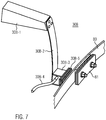
- the nacelle side contact device 30B (second contact device 30B) is shown in more detail in figure 7.
- Figure 7 shows a bracket 30B-1, a fibre glass profile 30B-2, an extension bracket 30B-3, and a contact element 30B-5, which is intended for slidingly contact with the lightning ring 80 which is mounted via bracket 81 to the spinner.
- the contact element 30B-5 is grounded to a cable 30B-4 which is grounded to the nacelle main structure.
- the bracket 30B-1 fixes the fibre glass profile 30B-2 to the nacelle front plate and bridges the distance between the grounded nacelle front plate and the nacelle front cover (not illustrated).
- One end of the fibre glass profile 30B-2 is fixed to the bracket 30B-1 and at the other end of the fibre glass profile 30B-2, the extension bracket 30B-3 is mounted, which bridges a certain distance through the nacelle front cover (not shown) to the lightning ring 80.
- the contact element 30B-5 is mounted to the extension bracket 30B-3 so that it is located outside the nacelle in front of the lightning ring 80.
- the nacelle side contact device 30B is configured so that the fibre glass profile 30B-2 can be provided with pretension so that the contact element 30B-5 is pressed against the lightning ring 80.
- the contact element 30B-5 may be designed in accordance with the international patent application WO 2005/05008 , for instance, illustrated in figure 8 thereof.
- the contact element 30B-5 basically may comprise a contact rod extending through a sliding pad.
- the rod preferably makes the electric contact to the rotating lightning ring 80 and the pad surrounding the rod ensures a low friction slide on the contact surface.
- the contact rod may be fixed to extension bracket 30B-3 by screwing a bolt into a threaded hole in the back side of the contact rod.
- the contact element to the combination of the contact rod and the sliding pad, it is collectively referred to as the contact element.
- the nacelle side contact element 30B-5 (second contact element 30B-5) and the spinner side contact element 70B (first contact element 70B, see figure 5 or 8 ) may have the same structure or may be different.
- figure 3 showing the lightning current transfer unit according to the state-of-the-art shows two different shapes of contact elements.
- Contact element 7A making the contact with the blade band 1A is a circular disk.
- the contact element 7F making the contact with the lightning ring 3B has a hexagonal structure with edges in a relative moving direction.
- the contact element 30B-5 in figure 7 may have a disk form or a hexagonal form.
- the contact rod may be made from an electric conductive material such as copper, aluminum, bronze, graphite, silver or composites thereof.
- bronze is used.
- the pad may be made of a low friction material such as nylon, acetal, Vesconite or glass filled nylon.
- Nylatron is used for the sliding pad.
- the contact element 30B-5 may be provided with a chamfered edge.
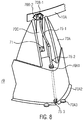
- FIG 8 shows a detailed view of the spinner side contact device 70 (first contact device 70) for providing contact with the blade band 10A.
- the spinner side contact device 70 comprises a (first) mounting element 70A to which a fibre glass profile 70C is mounted via a bracket 71.
- a contact element 70B-1 is mounted with a threaded bolt 70B-2 to the fibre glass profile 70C.
- a cable 75-1 is electrically connected with the bolt 70B-2 in order to make an electrical connection with the contact element 70B-1.
- the cable 75-1 is electrically connected with a lightning current transfer profile 75-2, which electrically connects the cable 75-1 with the connection bus 75-3.
- the lightning current transfer profile 75-2 is fixed to the fibre glass console 70 with a rubber fixture 70A1.
- connection bus 75-3 connects the lightning current transfer profile 75-2 with the lightning ring 80 which is mounted to the spinner in front of the nacelle.
- the connecting device 75 To the cable 75-1, the lightning current transfer profile 75-2 and the connection bus 75-3, it is collectively referred to as the connecting device 75, for instance, in figures 5 and 6 .
- the structure of the first contact element 70B may be the same as the nacelle side contact element 30B-5 as explained with figure 7 .
- the first mounting element fibre glass console 70A is fixed to the spinner at each blade to support the contact with the respective blade band 10A by means of threaded washers 70A3.
- the exposed part of the cable 75-1, the lightning current transfer profile 75-2 and the fibre glass profile 70C may be protected from environment by a cover (not shown in figure 8 , indicated in figure 6 ).
- the first mounting element fibre glass console 70A comprises a fibre glass console used as a mounting bracket and a cover protecting the contact elements.
- the fibre glass console may be 8mm thick and acts as a fastening bracket for the fibre glass profile 70C. It may be bolted onto the hub cover (spinner) at 4 points. Its non-conductivity enables it to be relatively large as to distribute the stresses over a larger area of the hub cover (spinner).
- the entire mounting element 70C (console including cover) can be dismounted from outside the hub by removing the four hub bolts and an additional bolt providing connection of the lightning current transfer profile 75-2 with the connection bus 75-3.
- Fibre glass profile 70C is provided with a pretension so that the contact element 70B-1 is pressed against the blade band 10A so as to ensure controlled lightning current transfer between the pitching blade and the lightning ring 80, i.e. a controlled high conductivity connection at least for very high voltages of more than 10,000 Volts.
- this invention has been made in order to provide a lightning current transfer system for larger wind turbines in which parts of well-known technology can be reused, wherein the lightning wear of the parts is reduced and all parts are exchangeable in-situ.
Landscapes
- Engineering & Computer Science (AREA)
- Life Sciences & Earth Sciences (AREA)
- Sustainable Development (AREA)
- Sustainable Energy (AREA)
- Chemical & Material Sciences (AREA)
- Combustion & Propulsion (AREA)
- Mechanical Engineering (AREA)
- General Engineering & Computer Science (AREA)
- Power Engineering (AREA)
- Wind Motors (AREA)
Description
- The invention relates to a lightning current transfer system adapted for usage in a wind turbine having a hub rotatably supported relative to a generator in a nacelle of the wind turbine and a plurality of blades pivotably connected with the hub. The invention also relates to a wind turbine in which the lightning current transfer system is implemented.
- Due to their size, wind turbines are prone to lightning strikes. The height of wind turbines overshoots by far surrounding trees and buildings in order to efficiently convert wind power into electric energy. If lightning strikes the tip of a blade of a wind turbine, the current flows in an uncontrolled manner through the blade, the blade bearings, the hub, the hub bearings, the generator shaft, the generator and the tower into the ground. Due to the high current values, there is a high risk that the bearings and electrical generators are damaged by the high voltages and currents flowing through the bearings and the generators. Therefore, efforts have been made to avoid damages in the turbine generators and the generator shaft bearings by offering a current path with lower impedance around the sensitive areas.
-
DE4445899 describes a lightning protection system for a wind turbine where there is a path to discharge lightning currents between the blades and ground.DE102004010104 describes a wind turbine with a lightning protection system where lightning current is discharged via a roller and a ring. -
JP 05/060053A - This solution has, however, the disadvantage that it does not consider that in modern wind turbines, the blades are pivotably connected to the hub through bearings in order to allow blade pitch control. These bearings may also be damaged by a high current flow. Therefore, efforts have been made in order to provide a short, low impedance connection between the root of the blade and the nacelle.
- A solution for this problem is shown in the international patent application
WO 2005/050008A1 disclosing a lightning current transfer unit which is collectively usable for a wide variety of turbine types. These turbines use a lightning current transfer unit (LCTU) that provides lightning current transfer from a blade band at the blade root to a nacelle lightning ring. The hub is relatively small compared to the nacelle so that the blade band and nacelle lightning ring can be positioned in opposition to each other. This situation is illustrated infigures 1 and2 .Figure 1 shows a wind turbine W with anacelle 3 containing the generator (not shown) sitting on thewind turbine tower 4. Theblades 1 supported by thehub 2 are connected through a generator shaft with the turbine generators in thenacelle 3. Within theblade 1, a bladelightning protection system 5 is provided in the form of a down conductor with thick conductive cables guiding the lightning power through the blades to the root of theblades 1. From there, the lightning current is transferred via thehub 2, thenacelle 3, and thetower 4 into ground G. -
Figures 2A and2B show a more detailed view of the encircled section I infigure 1 . InFigure 2A ,reference numeral 1 designates a blade,numeral 2 designates the hub,numeral 2A designates the spinner (the cover/housing of the hub),numeral 3 designates the nacelle,numeral 3A designates the front plate of the nacelle andreference numeral 6 designates the generator shaft which connects thehub 2 with the generator (not shown) in thenacelle 3. The lightning current transfer unit comprises ablade band 1A that is mounted at the root of theblade 1 and which is connected with the cables of the bladelightning protection system 5. Moreover, the LCTU comprises alightning ring 3B which is mounted at thenacelle front plate 3A. Thehub 2 is relatively small compared to thenacelle 3 so that theblade band 1A and thenacelle lightning ring 3B are positioned to face each other. That is, the diameter D1 of thehub 2 is smaller than the diameter D2 of thenacelle 3 so that theblade band 1A can rotate inside of the nacelle perimeter dimensions D2. This dimensional relationship allows the positioning of acompact connecting device 7 which electrically connects theblade band 1A which is rotatable around a blade axis 9, and thenacelle lightning ring 3B which rotates relative to the connectingdevice 7 around thehub axis 8. Thehub 2 and the connectingdevice 7 are collectively enclosed by a fibre glass cover to which it is referred as thespinner 2A. - The connecting
device 7 infigure 2A comprises abracket 7D, to which one end of twofibre glass profiles fibre glass profiles contact elements cable 7E connects thecontact elements figure 2A shows a small gap betweencontact elements 7A/7F andblade band 1A andlightning ring 3B, respectively, for illustration purposes. In operation, these contacts are sliding contacts. Bending forces of thefibre glass profiles contact elements blade band 1A and thelightning ring 3B to ensure a low impedance connection between theblade 1 and thenacelle 3 even ifcontact element 7F is rotating relative to thelightning ring 3B aroundaxis 8 and theblade band 1A is rotating relative to thecontact 7A around axis 9. When lightning strikes ablade 1, the lightning current is guided through thecable 5 of the blade lightning protection system to theblade band 1A, through thecontact 7A, theconnection cable 7E, thecontact element 7F to thelightning ring 3B which is mounted to thenacelle front plate 3A which is grounded through acable 3D with ground G. - A detailed view of the connecting
device 7 is given infigure 3 which again shows themounting bracket 7D, theglass fibre profiles contact elements cable 7E that electrically connects thecontact elements contact elements blade band 1A and thelightning ring 3B. -
Figure 2B shows a front view offigure 2A alongaxis 8 and illustrates the arrangement of the connectingdevices 7 with regard to threeblades 1. Eachblade 1 is provided with ablade band 1A and each blade band is contacted with a respective connectingdevice 7 so that three connecting devices are necessary. Each connectingdevice 7 is also in contact with thelightning ring 3B illustrated infigure 2B as a dashed line. The contour of thelightning ring 3B is within the perimeter of thespinner 2A. - A simplified 3-dimensional illustration of the
hub 2 and thespinner 2A is shown infigure 4 . Thespinner 2A has four openings, wherein theopenings 2A-1, 2A-2 and 2A-3 are intended for feeding through the three blades and the fourth opening 2A-4 is used to allow a connection of thehub 2 with thegenerator shaft 6. Thehub 2 includes four flanges 2-1, 2-2, 2-3 and 2-4 wherein the flanges 2-1, 2-2 and 2-3 are intended to mount a respective blade and flange 2-4 is intended to mount the generator shaft. Reference numerals 7-1, 7-2 and 7-3 symbolize three connecting devices as illustrated infigure 3 . The spinner opening 2A-4 is larger than the other openings in order to allow a connection of the connecting devices 7-1, 7-2 and 7-3 with the lightning ring at the nacelle through opening 2A-4.Figure 4 illustrates three connecting devices 7-1, 7-2 and 7-3, one for eachblade 1. - In recent times, there is a growing demand for larger wind turbines with pitch controllable blades, which leads to a larger hub so that finally, the blade band rotates outside of the nacelle perimeter. This has two consequences. At first, the v-shape of the
contact element 7 is no longer possible because it is not possible to place theblade band 1A opposite to thelightning ring 3B. Second, this also leads to an increased length of the connecting cable leading to higher impedance. A consequence of this is that the distance of the lightning protection system to sensitive parts like bearings and generators has to be increased in order to avoid discharges into the bearings and the generator. - It is therefore an object of this invention to provide a lightning current transfer system for large wind turbines which can use most of the parts of the lightning current transfer system of smaller wind turbines and which is maintainable in situ.
- The object is achieved by a wind turbine as claimed in
claim 1. - This arrangement has the advantage that the lightning current transfer system can be used for larger wind turbines with larger hubs wherein the blade band rotates outside of the nacelle perimeter. Moreover, this lightning current transfer system can be designed so that many of the parts of the lightning current transfer system for smaller wind turbines can be used and implemented for larger wind turbines in a new assembly. The lightning current transfer system of the present invention basically splits the integral connecting device of the state-of-the-art as described with reference to
figure 3 into two separate contact devices which also allow an increase of the respect distance (separation distance) to sensitive parts like bearings and generator parts. Another advantage is that the lightning ring can be mounted to the spinner and the second contact device are mountable to the nacelle which means that a plurality of second contact devices can be used on the nacelle side so that lightning current can be distributed over several contact points which reduces the current magnitude in one contact so that wear can also be reduced. This also adds redundancy and safety to the nacelle side lightning current transfer system in comparison to the prior art according tofigures 2-4 . In the case that lightning strikes a wind turbine with a lightning current transfer system according to the state of the art, current flows only through one contact point into the nacelle and increases therefore load and wear of the contact device in a lightning current transfer system of the prior art. - In one embodiment, the blade band and the first contact device are configured to be mounted outside the spinner and the connecting device for connecting the first contact device with the lightning ring is configured to be mounted inside the spinner.
- This configuration allows on one hand larger respect distances (separation distances) between the first contact device/connecting device and bearings or other sensitive parts. On the other hand, connecting cables (connecting device) between the first contact device and the lightning ring can be made shorter so as to reduce the impedance between these points.
- In another embodiment, the first contact device of the lightning current transfer system comprises a first mounting element mountable to the spinner, a first elastic non-conducting profile mounted to the first mounting element and a first contact element mounted at the first elastic non-conducting profile, wherein the first contact device is configured so that the first contact element faces the blade band and the first elastic non-conducting profile pushes the first contact element against the blade band.
- This embodiment has the advantage that the first contact element and the first elastic non-conducting profile of well-established preexisting lightning current transfer system like that illustrated in
figures 2a and3 can be reused. The first mounting element is designed to serve as a combination of a bracket (fixture for the first elastic non-conducting profile) and a cover which protects the first contact device against the environment because the first mounting element is mounted outside the spinner. According to a further embodiment, the first contact element comprises a conductive rod and a sliding element, wherein the conductive rod extends through a hole of the sliding element so that an end surface of the conductive rod and a surface of the sliding element collectively form a contact area for slidingly contacting the blade band. Thus, an electrical contact with small friction forces with the blade band can be established. Moreover, contact elements of established lightning current transfer units can be implemented in this invention, saving manufacturing costs. - In order to reduce the frictional forces of the sliding contact, the sliding element may be provided with a chamfered edge. This also improves ice sliding ability in case that icing occurs. The sliding area of the sliding element may have the shape of a hexagon with an edge of the hexagon in a moving direction of the sliding element so as to reduce friction in a sliding direction, in particular in case of a contaminated blade band surface.
- In order to reduce friction and wear of the sliding element, the sliding element may be made of Nylatron.
- In one embodiment, the second contact device comprises a second mounting element one end thereof being mountable to a front plate of the nacelle so that the second mounting element protrudes therefrom, a second elastic non-conducting profile mounted at one end to another end of the second mounting element, an extension bracket mounted at the second elastic non-conducting profile, and a second contact element mounted at the extension bracket, wherein the second contact device is configured so that the contact element may extend through a hole in a nacelle front cover so as to face the lightning ring mounted at the spinner, and the second elastic non-conducting profile pushes the second contact element against the lightning ring.
- In this embodiment, the second contact device, the elastic non-conducting profile and the second contact element of existing well-established lightning current transfer units can be used. Moreover, the first elastic non-conducting profile may have the same structure as the second elastic non-conducting profile and the first contact element may have the same structure as the second contact element so that the respective elements are interchangeable on one hand and can also be used for older well-established lightning current transfer systems like that illustrated in
figures 2a and3 . Moreover, the structure of the second contact device is configured to be mounted inside of the nacelle cover so that the second contact element can protrude through a small hole in the nacelle front cover to establish an electric contact with the lightning ring at the spinner. Moreover, bending forces of the pre-tensed second elastic non-conducting profile ensure that the contact element is pressed against the lightning ring for making a low impedance contact. - In order to add redundancy and to decrease the lightning current through each second contact, at least two second contact devices and more preferably, four second contact devices are used in a nacelle.
- In one embodiment, the first mounting element comprises a fibre glass console acting as a fastening bracket for the first elastic non-conducting profile and a cover for protection of the first contact element. As the first contact device is mounted outside the spinner, the contact element is exposed to environment influences. The construction of the first contact device allows a protection of the contact element from environmental conditions.
- In another embodiment, the second mounting element is a stainless steel bracket bridging the distance between the mechanically robust nacelle front plate and the nacelle front cover. Thus, the bracket can also be used as a tread for service personnel.
- In a further embodiment, the first elastic non-conducting profile and a second elastic non-conducting profile are fibre glass profiles. Fibre glass is a very robust, elastic and non-conductive material which can provide and transmit bending forces so as to establish a safe electrical contact between the contact elements on one side and the blade band and/or the lightning ring on the other side.
- In one embodiment thereof, the nacelle includes an inspection hatch in the nacelle front plate cover for inspecting the lightning ring. Thus, service can be provided in-situ.
- In the following, embodiments, examples, advantages and implementations of the invention will be explained in more detail by means of the accompanying figures. It is noted that all described and/or illustrated features alone or in arbitrary combination are basically subject matter of the invention, independently of the summary in the claims or the references in the claim. Also, the content of the claims is considered to be part of the description. In the figures show
-
Figure 1 : Schematically a wind turbine; -
Figure 2A : An enlarged view of the region I offigure 1 according to the state of the art; -
Figure 2B : A front view offigure 2A ; -
Figure 3 : A connection part of the lightning current transfer system according to the state of the art; -
Figure 4 : A schematic 3-dimensional view of a hub and a spinner according to the state of the art; -
Figure 5 : A schematical drawing of a lightning current transfer system according to the present invention mounted at a nacelle and a spinner; -
Figure 6 : A 3-dimensional view of an isolated lightning current transfer unit according to the present invention; -
Figure 7 : A 3-dimensional view of a second contact device according to the present invention; and -
Figure 8 : A 3-dimensional view of the first contact device of the present invention. - This invention has been made in order to provide a lightning current transfer system which can be used for wind turbines which are larger than the previous wind turbine constructions. In such larger wind turbines, the blades and the hub are increased in size so that the part of the lightning current transfer unit which is responsible for collecting the lightning current from the root of the blade rotates with the hub beyond the perimeter of the nacelle. Moreover, this invention has been made in order to allow at least partially the usage of lightning current transfer units according to the state-of-the-art. Moreover, all parts of the lightning current transfer unit of this invention shall be exchangeable in-situ and shall also reduce wear due to the lightning current.
-
Figure 5 gives an overview of the lightning current transfer system according to the present invention. Infigure 5 ,reference numeral 20 designates a hub, reference numeral 10 designates a blade,reference numeral 60 designates a shaft which connects thehub 20 with a generator (not shown) within thenacelle 30, and reference numeral 20A designates a spinner (aerodynamic housing of the hub 20).Figure 5 illustrates that thehub 20 is directly connected with theshaft 60 which in turn may be directly connected with the generator so as to implement a direct drive system. This invention is, however not restricted to such configurations. It is also possible to interpose a gearbox between the hub and the generator to convert a low speed rotational movement of the hub into a high speed rotational movement of a high speed shaft that drives the generator. The gearbox may be directly mounted to the hub or may be interposed between a low speed shaft from the hub and a high speed shaft from the generator. Therefore, in more general terms, the hub is rotatably supported relative to the generator. - The lightning current transfer system includes the
blade band 10A, thelightning ring 80, the blade part contact device 70 (also referred to as a first contact device 70) and nacelleside contact device 30B (also referred to as asecond contact device 30B). Bladepart contact device 70 includes the bladepart sliding contact 70B (also referred to asfirst contact element 70B), a nonconductive elasticglass fibre arm 70C (also referred to as first non-conductive elasticglass fibre profile 70C) and a first mountingelement 70A which fixes theglass fibre profile 70C to thespinner 20A and protects at the same time the slidingcontact 70B that is mounted at theglass fibre arm 70C against environment. Anelectrical connection 75 inside thespinner 20A connects the slidingcontact 70B with thelightning ring 80 which is mounted at the back side of thespinner 20A so as to face sliding contacts (also referred to as second contact element) of thenacelle contact device 30B (second contact device 30B). Rotation axes 8 and 9 indicate the same rotating capabilities of the spinner/hub and the blade are as described infigure 2A . - In general, the same reference numerals designate the same technical features in the figures and an omitted description of a particular reference number may be found in a description of a previous figure. Moreover, the dimensions and proportions in the figures have only illustrative character and are not intended to reflect a scale model. It is further noted that
figure 5 shows a small gap betweencontact elements 70B/30B andblade band 10A andlightning ring 80, respectively, for illustrative purposes. In operation, these contacts are sliding contacts and no gaps are visible. - It has to be noted that the lightning current transfer system according to this specification is exemplarily illustrated in form of sliding contacts that provide a low impedance connection. Thereby, the term "low impedance" is intended to describe an impedance for a lightning current transfer path that is lower than alternative lightning current transfer paths, so that the lightning current transfer can be controlled. In particular embodiments of this invention, the low impedance connection is provided with sliding contacts. This invention is, however, not restricted to sliding contacts. Moreover, the low impedance contacts may also be implemented as a spark gap-that is the electrical connection between the
blade band 10A and the first contact element may a spark gap and/or the electrical connection between thelightning ring 80 and thesecond contact device 30B may be a spark gap, rather than sliding contacts. In summary, a contact for a lightning current transfer has to be distinguished from a low energy (low voltage) electrical contact. The claimed contacts for lightning current transfer have to be electrically conductive for potential differences above several thousand volts due to the high voltages of lightning. Nevertheless, some embodiments also use contacts which are conductive at lower voltages (potential differences). Another implicit requirement of the claimed contacts is that their material can withstand very high current flow of up to several hundred thousand amperes. - The nacelle
side contact device 30B is mounted tofront plate 30A of thenacelle 30. - If a lightning strikes the blade 10, the lightning current is guided through cables within the blade 10 to a
blade band 10A. The elasticglass fibre arm 70C presses the slidingcontact 70B against theblade band 10A so as to ensure a conductive connection even if the blade 10 is pivoting/pitching around the axis 9. The lightning current is further guided through thecable 75 to thelightning ring 80 which is mounted on the nacelle side of thespinner 20A. Thenacelle contact device 30B also includes a sliding contact element which guides the lightning current from thelightning ring 80 to the groundedfront plate 30A of thenacelle 30. The routing of the lightning current through the cables of the blade, the spinner and the nacelle to the ground inherently includes a voltage drop along the cable. The larger the wind turbine, the higher is the risk that the current jumps from the desired current path to unwanted structural elements and continues through the shaft and main bearings. In order to prevent the current to jump from the desired current path to unwanted structural elements, a minimum respect distance needs to be kept to these structural elements. The larger the wind turbine, the larger these respect distances have to be. The positioning of the bladeside contact device 70 outside of the spinner increases the respect distance so that the required respect distance can be fulfilled. -
Figure 6 shows the isolated lightningcurrent transfer system 100 according to the present invention.Figure 6 shows thelightning ring 80 that is mounted vialightning ring brackets 81 to the spinner (not shown infigure 6 ). Thelightning ring 80 may be composed of several stainless steel segments which are fixed together with thelightning ring brackets 81.Figure 6 shows 10 lightning ring segments and tenlightning ring brackets 81. This number is, however, only used for illustrative purposes. Less than 10 stainless steel segments are possible and also more than 10 stainless steel segments are possible. Preferably, twelve stainless steel segments are used which leads to a manageable size of the segments which can be comfortably handled for in-situ maintenance from the nacelle, for instance, if a lightning ring segment has to be changed due to wear. -
Figure 6 also shows theblade band 10A which is a stainless steel plate, for instance, having a size of 4,000 x 80 x 3 mm. The stainless steel plate may be bolted and glued onto each blade. Attachment holes are positioned at each end of theblade band 10A. Further two holes may be positioned in an intermediate region of the blade band in order to fit the plate to the blade. The intermediate holes also serve as attachment points for the current transferring cable that run inside each blade. Since two contact points may be implemented in theblade band 10A, the lightning current is divided if the blade pitch angle causes the contact element in the first mountingelement 70A to be positioned between the two intermediate holes. Dividing the current reduces the needed respect distance and reduces also the wear of theblade band 10A. - Moreover,
figure 6 shows fournacelle contact device 30B (second contact device 30B) that are in sliding contact with thelightning ring 80. The blade side contact element inside thecomposite console 70A is connected with thelightning ring 80 viacable 75. - The nacelle
side contact device 30B (second contact device 30B) is shown in more detail infigure 7. Figure 7 shows abracket 30B-1, afibre glass profile 30B-2, anextension bracket 30B-3, and acontact element 30B-5, which is intended for slidingly contact with thelightning ring 80 which is mounted viabracket 81 to the spinner. Thecontact element 30B-5 is grounded to acable 30B-4 which is grounded to the nacelle main structure. - The
bracket 30B-1 fixes thefibre glass profile 30B-2 to the nacelle front plate and bridges the distance between the grounded nacelle front plate and the nacelle front cover (not illustrated). One end of thefibre glass profile 30B-2 is fixed to thebracket 30B-1 and at the other end of thefibre glass profile 30B-2, theextension bracket 30B-3 is mounted, which bridges a certain distance through the nacelle front cover (not shown) to thelightning ring 80. Thecontact element 30B-5 is mounted to theextension bracket 30B-3 so that it is located outside the nacelle in front of thelightning ring 80. The nacelleside contact device 30B is configured so that thefibre glass profile 30B-2 can be provided with pretension so that thecontact element 30B-5 is pressed against thelightning ring 80. - The
contact element 30B-5 may be designed in accordance with the international patent applicationWO 2005/05008 figure 8 thereof. Thecontact element 30B-5 basically may comprise a contact rod extending through a sliding pad. The rod preferably makes the electric contact to therotating lightning ring 80 and the pad surrounding the rod ensures a low friction slide on the contact surface. The contact rod may be fixed toextension bracket 30B-3 by screwing a bolt into a threaded hole in the back side of the contact rod. In this description, to the combination of the contact rod and the sliding pad, it is collectively referred to as the contact element. The nacelleside contact element 30B-5 (second contact element 30B-5) and the spinnerside contact element 70B (first contact element 70B, seefigure 5 or8 ) may have the same structure or may be different. For instance,figure 3 showing the lightning current transfer unit according to the state-of-the-art shows two different shapes of contact elements.Contact element 7A making the contact with theblade band 1A is a circular disk. Thecontact element 7F making the contact with thelightning ring 3B has a hexagonal structure with edges in a relative moving direction. Similarly, thecontact element 30B-5 infigure 7 may have a disk form or a hexagonal form. - The contact rod may be made from an electric conductive material such as copper, aluminum, bronze, graphite, silver or composites thereof. Preferably, bronze is used. The pad may be made of a low friction material such as nylon, acetal, Vesconite or glass filled nylon. Preferably, Nylatron is used for the sliding pad. In order to improve the sliding properties and adaptability to ice layers on the
lightning ring 80, thecontact element 30B-5 may be provided with a chamfered edge. -
Figure 8 shows a detailed view of the spinner side contact device 70 (first contact device 70) for providing contact with theblade band 10A. The spinnerside contact device 70 comprises a (first) mountingelement 70A to which afibre glass profile 70C is mounted via abracket 71. Acontact element 70B-1 is mounted with a threadedbolt 70B-2 to thefibre glass profile 70C. A cable 75-1 is electrically connected with thebolt 70B-2 in order to make an electrical connection with thecontact element 70B-1. The cable 75-1 is electrically connected with a lightning current transfer profile 75-2, which electrically connects the cable 75-1 with the connection bus 75-3. The lightning current transfer profile 75-2 is fixed to thefibre glass console 70 with a rubber fixture 70A1. The connection bus 75-3 connects the lightning current transfer profile 75-2 with thelightning ring 80 which is mounted to the spinner in front of the nacelle. To the cable 75-1, the lightning current transfer profile 75-2 and the connection bus 75-3, it is collectively referred to as the connectingdevice 75, for instance, infigures 5 and6 . To the blade side contact element including thecontact element 70B-1 and thebolt 70B-2, it is collectively referred to as thefirst contact element 70B (see for instancefigure 5 ). The structure of thefirst contact element 70B may be the same as the nacelleside contact element 30B-5 as explained withfigure 7 . - The first mounting element
fibre glass console 70A is fixed to the spinner at each blade to support the contact with therespective blade band 10A by means of threaded washers 70A3. The exposed part of the cable 75-1, the lightning current transfer profile 75-2 and thefibre glass profile 70C may be protected from environment by a cover (not shown infigure 8 , indicated infigure 6 ). The first mounting elementfibre glass console 70A comprises a fibre glass console used as a mounting bracket and a cover protecting the contact elements. - The fibre glass console may be 8mm thick and acts as a fastening bracket for the
fibre glass profile 70C. It may be bolted onto the hub cover (spinner) at 4 points. Its non-conductivity enables it to be relatively large as to distribute the stresses over a larger area of the hub cover (spinner). - The
entire mounting element 70C (console including cover) can be dismounted from outside the hub by removing the four hub bolts and an additional bolt providing connection of the lightning current transfer profile 75-2 with the connection bus 75-3.Fibre glass profile 70C is provided with a pretension so that thecontact element 70B-1 is pressed against theblade band 10A so as to ensure controlled lightning current transfer between the pitching blade and thelightning ring 80, i.e. a controlled high conductivity connection at least for very high voltages of more than 10,000 Volts. - In conclusion, this invention has been made in order to provide a lightning current transfer system for larger wind turbines in which parts of well-known technology can be reused, wherein the lightning wear of the parts is reduced and all parts are exchangeable in-situ.
Claims (13)
- A wind turbine (W) having a hub (20) rotatably supported relative to a generator in a nacelle (30), a plurality of blades (10) pivotably connected with the hub (20) and a lightning current transfer system (100), wherein the hub (20) is covered by a spinner (20A), the lightning current transfer system comprising
a blade band (10A) mounted to a root of the blade (10);
a lightning ring (80) mounted to the spinner (20A) facing the nacelle (30);
a first contact device (70) mounted to the spinner (20A) for providing lightning current transfer from the blade band (10A);
a connecting device (75) connecting the first contact device (70) with the lightning ring (80); and
a second contact device (30B) mounted to the nacelle (30) for providing lightning current transfer from the lightning ring (80);
wherein the hub (20) has a radial extension (D1) so that the blade band (10A) rotates outside a perimeter of the nacelle (30). - The wind turbine according to claim 1, wherein:the blade band (10A) and the first contact device (70) are mounted outside the spinner (20A); andthe connecting device (75) is mounted inside the spinner (20A).
- The wind turbine according to claim 1 or claim 2, wherein the first contact device (70) comprises:a first mounting element (70A) mounted to the spinner (20A);a first elastic non-conducting profile (70C) mounted to the first mounting element (70A); anda first contact element (70B) mounted at the first elastic non-conducting profile (70C);wherein the first contact device (70) is configured so that the first contact element (70B) faces the blade band (10A) and the first elastic non-conducting profile (70C) pushes the first contact element (70B) against the blade band (10A).
- The wind turbine according to claim 3, wherein the first contact element (70B) comprises:a conductive rod; anda sliding element (70B-1),wherein the conductive rod extends through a hole of the sliding element so that an end surface of the conductive rod and a surface of the sliding element collectively form a contact area for slidingly contacting the blade band (10A).
- The wind turbine according to claim 4, wherein the sliding element (70B-1) has a chamfered edge.
- The wind turbine according to any one of the claims 1-5, wherein the second contact device (30B) comprises:a second mounting element (30B-1) mounted at one end to a front plate (30A) of the nacelle (30) thereby protruding therefrom;a second elastic non-conducting profile (30B-2) mounted at one end to another end of the second mounting element (30B-1);a second contact element mounted at the second elastic non-conducting profile (30B-1),wherein the second contact device (30B) is configured so that the contact element faces the lightning ring (80) and the second elastic non-conducting profile (30B-2) pushes the second contact element against the lightning ring (80).
- The wind turbine according to claim 3 and 6, wherein the first elastic non-conducting profile (70C) has the same structure as the second elastic non-conducting profile (30B-2) so that these elements are interchangeable.
- The wind turbine according to claim 7, wherein the first contact element (70B) has the same structure as the second contact element so that these elements are interchangeable.
- The wind turbine according to any one of the preceding claims comprising at least two second contact device (30B), preferably four second contact device (30B).
- The wind turbine according to any one of the claims 3 - 9, wherein the first mounting element (70A) comprises:a fibre glass console acting as a fastening bracket for the first elastic non-conducting profile (70C); anda cover for protecting the first contact element (70B).
- The wind turbine according to any one of the claims 7 - 10, wherein the second mounting element (30B-1) is a stainless steel bracket.
- The wind turbine according to any one of the claims 3 11, wherein the first elastic non-conducting profile (70C) and/or the second elastic non-conducting profile (30B-2) is a fibre glass profile.
- The wind turbine according to claim 1, wherein the nacelle (30) includes an inspection hatch for in situ inspecting the lightning ring (80).
Applications Claiming Priority (2)
| Application Number | Priority Date | Filing Date | Title |
|---|---|---|---|
| DKPA201370560 | 2013-10-07 | ||
| PCT/DK2014/050311 WO2015051800A1 (en) | 2013-10-07 | 2014-10-03 | Lightning current transfer system and wind turbine using the lightning current transfer system |
Publications (2)
| Publication Number | Publication Date |
|---|---|
| EP3055559A1 EP3055559A1 (en) | 2016-08-17 |
| EP3055559B1 true EP3055559B1 (en) | 2020-09-23 |
Family
ID=51794699
Family Applications (1)
| Application Number | Title | Priority Date | Filing Date |
|---|---|---|---|
| EP14789151.9A Active EP3055559B1 (en) | 2013-10-07 | 2014-10-03 | Lightning current transfer system and wind turbine using the lightning current transfer system |
Country Status (7)
| Country | Link |
|---|---|
| US (1) | US10066607B2 (en) |
| EP (1) | EP3055559B1 (en) |
| JP (1) | JP6333366B2 (en) |
| KR (1) | KR20160067953A (en) |
| CN (1) | CN105793564B (en) |
| DK (1) | DK3055559T3 (en) |
| WO (1) | WO2015051800A1 (en) |
Families Citing this family (16)
| Publication number | Priority date | Publication date | Assignee | Title |
|---|---|---|---|---|
| EP3255276B1 (en) * | 2016-06-09 | 2019-02-27 | Siemens Aktiengesellschaft | Lighting protection system for a wind turbine |
| US20190383275A1 (en) * | 2017-01-23 | 2019-12-19 | Lagerwey Wind B.V. | Wind power system with low electromagnetic interference |
| US11592006B2 (en) | 2017-02-21 | 2023-02-28 | Siemens Gamesa Renewable Energy A/S | Wind turbine comprising a grounding system for transferring lightning current and for providing EMF shielding |
| DE102017114151A1 (en) * | 2017-06-26 | 2018-12-27 | Eno Energy Systems Gmbh | Lightning protection system for a rotor blade |
| ES2731173B2 (en) | 2018-05-14 | 2020-12-09 | Siemens Gamesa Renewable Energy Innovation & Technology SL | Electrical protection system for wind turbines |
| JP6916221B2 (en) * | 2019-01-25 | 2021-08-11 | 三菱重工業株式会社 | Windmill lightning current transmission system |
| ES2802125A1 (en) | 2019-07-05 | 2021-01-15 | Siemens Gamesa Renewable Energy Innovation & Technology SL | Lightning discharge system for a wind turbine (Machine-translation by Google Translate, not legally binding) |
| EP3786451A1 (en) * | 2019-08-28 | 2021-03-03 | Siemens Gamesa Renewable Energy A/S | Wind turbine |
| EP4063650B1 (en) * | 2021-03-24 | 2025-10-22 | Siemens Gamesa Renewable Energy A/S | Lightning magnetic flux density reduction in wind turbines |
| CN113586328B (en) * | 2021-06-01 | 2024-01-30 | 国电联合动力技术有限公司 | Wind wheel assembly and fan |
| JP2023137638A (en) * | 2022-03-18 | 2023-09-29 | 日軽金アクト株式会社 | Blade fixing structure of vertical axis wind turbine |
| EP4594634A1 (en) | 2022-09-30 | 2025-08-06 | Vestas Wind Systems A/S | Improvements relating to wind turbine blade anti-icing systems |
| CN120322617A (en) | 2022-12-09 | 2025-07-15 | 维斯塔斯风力系统有限公司 | Wind turbines with lightning current transmission systems |
| CN116576079B (en) * | 2023-05-23 | 2023-11-17 | 上海玻璃钢研究院东台有限公司 | Blade lightning arrester of wind driven generator |
| WO2025131199A1 (en) * | 2023-12-19 | 2025-06-26 | Vestas Wind Systems A/S | Lightning current transfer system |
| FR3162425B1 (en) * | 2024-05-24 | 2026-04-24 | Safran Aircraft Engines | TURBOMACHINE KIT INCLUDING A LIGHTNING SENSOR SYSTEM |
Family Cites Families (17)
| Publication number | Priority date | Publication date | Assignee | Title |
|---|---|---|---|---|
| JPH0560053A (en) | 1991-08-26 | 1993-03-09 | Mitsubishi Heavy Ind Ltd | Windmill |
| DE4436197C2 (en) * | 1994-10-11 | 1998-09-24 | Aloys Wobben | Wind turbine with lightning protection device |
| DE4445899A1 (en) * | 1994-12-22 | 1996-06-27 | Autoflug Energietech Gmbh | Wind turbine generator with lighting protection |
| JP2000265938A (en) | 1999-03-17 | 2000-09-26 | Hitachi Ltd | Lightning protection system for wind power |
| DE10022128C1 (en) | 2000-05-06 | 2001-12-20 | Aloys Wobben | Wind turbine |
| DK177270B1 (en) * | 2002-11-12 | 2012-09-10 | Lm Wind Power As | Lightning protection of pitch-regulated wind turbine wings |
| JP2004225660A (en) * | 2003-01-27 | 2004-08-12 | Tohoku Electric Power Co Inc | Thunder-resistant wind power generation system |
| WO2005005008A1 (en) | 2003-07-11 | 2005-01-20 | Kwan-Young Kim | An assembling block |
| JP4313364B2 (en) | 2003-11-20 | 2009-08-12 | ヴェスタス,ウィンド,システムズ エー/エス | Wind turbine, lightning connection means, method and use thereof |
| DE102004010104A1 (en) * | 2004-02-27 | 2005-09-29 | Repower Systems Ag | Wind turbine generator is protected against lightning strikes by a conductor system coupled to ground |
| JP4595086B2 (en) | 2004-09-06 | 2010-12-08 | 学校法人 関西大学 | Wind turbine generator having a lightning protection system for windmill blades |
| ES2265776B1 (en) | 2005-08-01 | 2008-02-01 | GAMESA INNOVATION & TECHNOLOGY, S.L. | NON-CONTACT RAY TRANSMISSION SYSTEM. |
| WO2008089760A1 (en) * | 2007-01-23 | 2008-07-31 | Vestas Wind Systems A/S | Flexible electric power cable and wind turbine |
| IT1393707B1 (en) * | 2009-04-29 | 2012-05-08 | Rolic Invest Sarl | WIND POWER PLANT FOR THE GENERATION OF ELECTRICITY |
| WO2011131205A1 (en) | 2010-04-19 | 2011-10-27 | Vestas Wind Systems A/S | Lightning current transfer unit, wind turbine, method and use thereof |
| DK2395238T3 (en) | 2010-06-10 | 2014-04-22 | Siemens Ag | Wind turbine with a lightning protection system |
| US20190195203A1 (en) | 2011-12-09 | 2019-06-27 | Mitsubishi Heavy Industries, Ltd. | Wind turbine blade for a wind turbine |
-
2014
- 2014-10-03 JP JP2016521339A patent/JP6333366B2/en active Active
- 2014-10-03 US US15/027,901 patent/US10066607B2/en active Active
- 2014-10-03 DK DK14789151.9T patent/DK3055559T3/en active
- 2014-10-03 KR KR1020167012042A patent/KR20160067953A/en not_active Ceased
- 2014-10-03 WO PCT/DK2014/050311 patent/WO2015051800A1/en not_active Ceased
- 2014-10-03 EP EP14789151.9A patent/EP3055559B1/en active Active
- 2014-10-03 CN CN201480065723.8A patent/CN105793564B/en active Active
Non-Patent Citations (1)
| Title |
|---|
| None * |
Also Published As
| Publication number | Publication date |
|---|---|
| EP3055559A1 (en) | 2016-08-17 |
| KR20160067953A (en) | 2016-06-14 |
| JP2016538451A (en) | 2016-12-08 |
| US20160252078A1 (en) | 2016-09-01 |
| WO2015051800A1 (en) | 2015-04-16 |
| DK3055559T3 (en) | 2020-10-26 |
| CN105793564B (en) | 2019-03-12 |
| US10066607B2 (en) | 2018-09-04 |
| CN105793564A (en) | 2016-07-20 |
| JP6333366B2 (en) | 2018-05-30 |
Similar Documents
| Publication | Publication Date | Title |
|---|---|---|
| US10066607B2 (en) | Lightning current transfer system and wind turbine using the lightning current transfer system | |
| EP2789067B1 (en) | Lightning current transfer system for a wind turbine generator | |
| EP2510229B1 (en) | Wind turbine with a lightning protection system | |
| EP3060796B1 (en) | Lightning current transfer system with spark gap and wind turbine using the lightning current transfer system | |
| EP2795122B1 (en) | Wind turbine generator system and lightning protection device thereof | |
| EP2889477A1 (en) | Wind turbine lightning protection system and corresponding wind turbine rotor | |
| US7502215B2 (en) | Systems and methods for directing a current | |
| CA2500643A1 (en) | Lightning protection of a pitch-controlled wind turbine blade | |
| US12104577B2 (en) | Blade for a wind turbine and wind turbine | |
| WO2013182447A1 (en) | A wind turbine blade lightning bypass system | |
| EP3284948B1 (en) | Wind power system for generating electric energy | |
| US20140119919A1 (en) | Wind turbine | |
| EP3080447B1 (en) | Rotor-blade discharge unit for wind turbines | |
| EP3712429B1 (en) | Lightning protection for a direct drive wind turbine | |
| EP3935280B1 (en) | Electrical connection device for a wind turbine, wind turbine and method for producing an electrical connection device | |
| CN107917050B (en) | Lightning current transmission system for wind turbine | |
| US10051717B2 (en) | Electrostatic noise grounding system for use in a wind turbine and a rotor and wind turbine comprising the same | |
| WO2026061596A1 (en) | Lightning current transfer unit and wind turbine comprising same | |
| WO2025093095A1 (en) | Wind turbine ice protection | |
| CN120735960A (en) | Electric motor, electric propulsion device and aircraft |
Legal Events
| Date | Code | Title | Description |
|---|---|---|---|
| PUAI | Public reference made under article 153(3) epc to a published international application that has entered the european phase |
Free format text: ORIGINAL CODE: 0009012 |
|
| 17P | Request for examination filed |
Effective date: 20160422 |
|
| AK | Designated contracting states |
Kind code of ref document: A1 Designated state(s): AL AT BE BG CH CY CZ DE DK EE ES FI FR GB GR HR HU IE IS IT LI LT LU LV MC MK MT NL NO PL PT RO RS SE SI SK SM TR |
|
| AX | Request for extension of the european patent |
Extension state: BA ME |
|
| DAX | Request for extension of the european patent (deleted) | ||
| STAA | Information on the status of an ep patent application or granted ep patent |
Free format text: STATUS: EXAMINATION IS IN PROGRESS |
|
| 17Q | First examination report despatched |
Effective date: 20190204 |
|
| GRAP | Despatch of communication of intention to grant a patent |
Free format text: ORIGINAL CODE: EPIDOSNIGR1 |
|
| STAA | Information on the status of an ep patent application or granted ep patent |
Free format text: STATUS: GRANT OF PATENT IS INTENDED |
|
| RIC1 | Information provided on ipc code assigned before grant |
Ipc: F03D 9/25 20160101ALI20200323BHEP Ipc: F03D 13/00 20160101AFI20200323BHEP Ipc: F03D 80/30 20160101ALI20200323BHEP |
|
| INTG | Intention to grant announced |
Effective date: 20200417 |
|
| GRAS | Grant fee paid |
Free format text: ORIGINAL CODE: EPIDOSNIGR3 |
|
| GRAA | (expected) grant |
Free format text: ORIGINAL CODE: 0009210 |
|
| STAA | Information on the status of an ep patent application or granted ep patent |
Free format text: STATUS: THE PATENT HAS BEEN GRANTED |
|
| AK | Designated contracting states |
Kind code of ref document: B1 Designated state(s): AL AT BE BG CH CY CZ DE DK EE ES FI FR GB GR HR HU IE IS IT LI LT LU LV MC MK MT NL NO PL PT RO RS SE SI SK SM TR |
|
| REG | Reference to a national code |
Ref country code: GB Ref legal event code: FG4D |
|
| REG | Reference to a national code |
Ref country code: CH Ref legal event code: EP |
|
| REG | Reference to a national code |
Ref country code: IE Ref legal event code: FG4D |
|
| REG | Reference to a national code |
Ref country code: DE Ref legal event code: R096 Ref document number: 602014070525 Country of ref document: DE Ref country code: AT Ref legal event code: REF Ref document number: 1316622 Country of ref document: AT Kind code of ref document: T Effective date: 20201015 |
|
| REG | Reference to a national code |
Ref country code: DK Ref legal event code: T3 Effective date: 20201021 |
|
| PG25 | Lapsed in a contracting state [announced via postgrant information from national office to epo] |
Ref country code: HR Free format text: LAPSE BECAUSE OF FAILURE TO SUBMIT A TRANSLATION OF THE DESCRIPTION OR TO PAY THE FEE WITHIN THE PRESCRIBED TIME-LIMIT Effective date: 20200923 Ref country code: SE Free format text: LAPSE BECAUSE OF FAILURE TO SUBMIT A TRANSLATION OF THE DESCRIPTION OR TO PAY THE FEE WITHIN THE PRESCRIBED TIME-LIMIT Effective date: 20200923 Ref country code: BG Free format text: LAPSE BECAUSE OF FAILURE TO SUBMIT A TRANSLATION OF THE DESCRIPTION OR TO PAY THE FEE WITHIN THE PRESCRIBED TIME-LIMIT Effective date: 20201223 Ref country code: NO Free format text: LAPSE BECAUSE OF FAILURE TO SUBMIT A TRANSLATION OF THE DESCRIPTION OR TO PAY THE FEE WITHIN THE PRESCRIBED TIME-LIMIT Effective date: 20201223 Ref country code: FI Free format text: LAPSE BECAUSE OF FAILURE TO SUBMIT A TRANSLATION OF THE DESCRIPTION OR TO PAY THE FEE WITHIN THE PRESCRIBED TIME-LIMIT Effective date: 20200923 Ref country code: GR Free format text: LAPSE BECAUSE OF FAILURE TO SUBMIT A TRANSLATION OF THE DESCRIPTION OR TO PAY THE FEE WITHIN THE PRESCRIBED TIME-LIMIT Effective date: 20201224 |
|
| REG | Reference to a national code |
Ref country code: AT Ref legal event code: MK05 Ref document number: 1316622 Country of ref document: AT Kind code of ref document: T Effective date: 20200923 |
|
| PG25 | Lapsed in a contracting state [announced via postgrant information from national office to epo] |
Ref country code: RS Free format text: LAPSE BECAUSE OF FAILURE TO SUBMIT A TRANSLATION OF THE DESCRIPTION OR TO PAY THE FEE WITHIN THE PRESCRIBED TIME-LIMIT Effective date: 20200923 Ref country code: LV Free format text: LAPSE BECAUSE OF FAILURE TO SUBMIT A TRANSLATION OF THE DESCRIPTION OR TO PAY THE FEE WITHIN THE PRESCRIBED TIME-LIMIT Effective date: 20200923 |
|
| REG | Reference to a national code |
Ref country code: NL Ref legal event code: MP Effective date: 20200923 |
|
| REG | Reference to a national code |
Ref country code: LT Ref legal event code: MG4D |
|
| PG25 | Lapsed in a contracting state [announced via postgrant information from national office to epo] |
Ref country code: EE Free format text: LAPSE BECAUSE OF FAILURE TO SUBMIT A TRANSLATION OF THE DESCRIPTION OR TO PAY THE FEE WITHIN THE PRESCRIBED TIME-LIMIT Effective date: 20200923 Ref country code: RO Free format text: LAPSE BECAUSE OF FAILURE TO SUBMIT A TRANSLATION OF THE DESCRIPTION OR TO PAY THE FEE WITHIN THE PRESCRIBED TIME-LIMIT Effective date: 20200923 Ref country code: SM Free format text: LAPSE BECAUSE OF FAILURE TO SUBMIT A TRANSLATION OF THE DESCRIPTION OR TO PAY THE FEE WITHIN THE PRESCRIBED TIME-LIMIT Effective date: 20200923 Ref country code: NL Free format text: LAPSE BECAUSE OF FAILURE TO SUBMIT A TRANSLATION OF THE DESCRIPTION OR TO PAY THE FEE WITHIN THE PRESCRIBED TIME-LIMIT Effective date: 20200923 Ref country code: LT Free format text: LAPSE BECAUSE OF FAILURE TO SUBMIT A TRANSLATION OF THE DESCRIPTION OR TO PAY THE FEE WITHIN THE PRESCRIBED TIME-LIMIT Effective date: 20200923 Ref country code: PT Free format text: LAPSE BECAUSE OF FAILURE TO SUBMIT A TRANSLATION OF THE DESCRIPTION OR TO PAY THE FEE WITHIN THE PRESCRIBED TIME-LIMIT Effective date: 20210125 Ref country code: CZ Free format text: LAPSE BECAUSE OF FAILURE TO SUBMIT A TRANSLATION OF THE DESCRIPTION OR TO PAY THE FEE WITHIN THE PRESCRIBED TIME-LIMIT Effective date: 20200923 |
|
| PG25 | Lapsed in a contracting state [announced via postgrant information from national office to epo] |
Ref country code: PL Free format text: LAPSE BECAUSE OF FAILURE TO SUBMIT A TRANSLATION OF THE DESCRIPTION OR TO PAY THE FEE WITHIN THE PRESCRIBED TIME-LIMIT Effective date: 20200923 Ref country code: IS Free format text: LAPSE BECAUSE OF FAILURE TO SUBMIT A TRANSLATION OF THE DESCRIPTION OR TO PAY THE FEE WITHIN THE PRESCRIBED TIME-LIMIT Effective date: 20210123 Ref country code: AT Free format text: LAPSE BECAUSE OF FAILURE TO SUBMIT A TRANSLATION OF THE DESCRIPTION OR TO PAY THE FEE WITHIN THE PRESCRIBED TIME-LIMIT Effective date: 20200923 Ref country code: AL Free format text: LAPSE BECAUSE OF FAILURE TO SUBMIT A TRANSLATION OF THE DESCRIPTION OR TO PAY THE FEE WITHIN THE PRESCRIBED TIME-LIMIT Effective date: 20200923 Ref country code: ES Free format text: LAPSE BECAUSE OF FAILURE TO SUBMIT A TRANSLATION OF THE DESCRIPTION OR TO PAY THE FEE WITHIN THE PRESCRIBED TIME-LIMIT Effective date: 20200923 |
|
| REG | Reference to a national code |
Ref country code: CH Ref legal event code: PL |
|
| REG | Reference to a national code |
Ref country code: DE Ref legal event code: R097 Ref document number: 602014070525 Country of ref document: DE |
|
| PG25 | Lapsed in a contracting state [announced via postgrant information from national office to epo] |
Ref country code: LU Free format text: LAPSE BECAUSE OF NON-PAYMENT OF DUE FEES Effective date: 20201003 Ref country code: SK Free format text: LAPSE BECAUSE OF FAILURE TO SUBMIT A TRANSLATION OF THE DESCRIPTION OR TO PAY THE FEE WITHIN THE PRESCRIBED TIME-LIMIT Effective date: 20200923 Ref country code: MC Free format text: LAPSE BECAUSE OF FAILURE TO SUBMIT A TRANSLATION OF THE DESCRIPTION OR TO PAY THE FEE WITHIN THE PRESCRIBED TIME-LIMIT Effective date: 20200923 |
|
| REG | Reference to a national code |
Ref country code: BE Ref legal event code: MM Effective date: 20201031 |
|
| PLBE | No opposition filed within time limit |
Free format text: ORIGINAL CODE: 0009261 |
|
| STAA | Information on the status of an ep patent application or granted ep patent |
Free format text: STATUS: NO OPPOSITION FILED WITHIN TIME LIMIT |
|
| PG25 | Lapsed in a contracting state [announced via postgrant information from national office to epo] |
Ref country code: BE Free format text: LAPSE BECAUSE OF NON-PAYMENT OF DUE FEES Effective date: 20201031 Ref country code: CH Free format text: LAPSE BECAUSE OF NON-PAYMENT OF DUE FEES Effective date: 20201031 Ref country code: SI Free format text: LAPSE BECAUSE OF FAILURE TO SUBMIT A TRANSLATION OF THE DESCRIPTION OR TO PAY THE FEE WITHIN THE PRESCRIBED TIME-LIMIT Effective date: 20200923 Ref country code: LI Free format text: LAPSE BECAUSE OF NON-PAYMENT OF DUE FEES Effective date: 20201031 |
|
| 26N | No opposition filed |
Effective date: 20210624 |
|
| PG25 | Lapsed in a contracting state [announced via postgrant information from national office to epo] |
Ref country code: IE Free format text: LAPSE BECAUSE OF NON-PAYMENT OF DUE FEES Effective date: 20201003 Ref country code: IT Free format text: LAPSE BECAUSE OF FAILURE TO SUBMIT A TRANSLATION OF THE DESCRIPTION OR TO PAY THE FEE WITHIN THE PRESCRIBED TIME-LIMIT Effective date: 20200923 |
|
| PG25 | Lapsed in a contracting state [announced via postgrant information from national office to epo] |
Ref country code: TR Free format text: LAPSE BECAUSE OF FAILURE TO SUBMIT A TRANSLATION OF THE DESCRIPTION OR TO PAY THE FEE WITHIN THE PRESCRIBED TIME-LIMIT Effective date: 20200923 Ref country code: MT Free format text: LAPSE BECAUSE OF FAILURE TO SUBMIT A TRANSLATION OF THE DESCRIPTION OR TO PAY THE FEE WITHIN THE PRESCRIBED TIME-LIMIT Effective date: 20200923 Ref country code: CY Free format text: LAPSE BECAUSE OF FAILURE TO SUBMIT A TRANSLATION OF THE DESCRIPTION OR TO PAY THE FEE WITHIN THE PRESCRIBED TIME-LIMIT Effective date: 20200923 |
|
| PG25 | Lapsed in a contracting state [announced via postgrant information from national office to epo] |
Ref country code: MK Free format text: LAPSE BECAUSE OF FAILURE TO SUBMIT A TRANSLATION OF THE DESCRIPTION OR TO PAY THE FEE WITHIN THE PRESCRIBED TIME-LIMIT Effective date: 20200923 |
|
| P01 | Opt-out of the competence of the unified patent court (upc) registered |
Effective date: 20230521 |
|
| PGFP | Annual fee paid to national office [announced via postgrant information from national office to epo] |
Ref country code: DE Payment date: 20251028 Year of fee payment: 12 |
|
| PGFP | Annual fee paid to national office [announced via postgrant information from national office to epo] |
Ref country code: GB Payment date: 20251023 Year of fee payment: 12 |
|
| PGFP | Annual fee paid to national office [announced via postgrant information from national office to epo] |
Ref country code: DK Payment date: 20251024 Year of fee payment: 12 |
|
| PGFP | Annual fee paid to national office [announced via postgrant information from national office to epo] |
Ref country code: FR Payment date: 20251027 Year of fee payment: 12 |