EP3054546A1 - Digital protective relay - Google Patents
Digital protective relay Download PDFInfo
- Publication number
- EP3054546A1 EP3054546A1 EP16152272.7A EP16152272A EP3054546A1 EP 3054546 A1 EP3054546 A1 EP 3054546A1 EP 16152272 A EP16152272 A EP 16152272A EP 3054546 A1 EP3054546 A1 EP 3054546A1
- Authority
- EP
- European Patent Office
- Prior art keywords
- electrical
- digital
- digital signal
- inflection point
- processor
- Prior art date
- Legal status (The legal status is an assumption and is not a legal conclusion. Google has not performed a legal analysis and makes no representation as to the accuracy of the status listed.)
- Withdrawn
Links
Images



Classifications
-
- G—PHYSICS
- G01—MEASURING; TESTING
- G01R—MEASURING ELECTRIC VARIABLES; MEASURING MAGNETIC VARIABLES
- G01R19/00—Arrangements for measuring currents or voltages or for indicating presence or sign thereof
- G01R19/165—Indicating that current or voltage is either above or below a predetermined value or within or outside a predetermined range of values
- G01R19/16504—Indicating that current or voltage is either above or below a predetermined value or within or outside a predetermined range of values characterised by the components employed
- G01R19/16509—Indicating that current or voltage is either above or below a predetermined value or within or outside a predetermined range of values characterised by the components employed using electromagnetic relays, e.g. reed relay
-
- H—ELECTRICITY
- H03—ELECTRONIC CIRCUITRY
- H03M—CODING; DECODING; CODE CONVERSION IN GENERAL
- H03M1/00—Analogue/digital conversion; Digital/analogue conversion
- H03M1/12—Analogue/digital converters
-
- H—ELECTRICITY
- H02—GENERATION; CONVERSION OR DISTRIBUTION OF ELECTRIC POWER
- H02H—EMERGENCY PROTECTIVE CIRCUIT ARRANGEMENTS
- H02H7/00—Emergency protective circuit arrangements specially adapted for specific types of electric machines or apparatus or for sectionalised protection of cable or line systems, and effecting automatic switching in the event of an undesired change from normal working conditions
- H02H7/26—Sectionalised protection of cable or line systems, e.g. for disconnecting a section on which a short-circuit, earth fault, or arc discharge has occured
- H02H7/261—Sectionalised protection of cable or line systems, e.g. for disconnecting a section on which a short-circuit, earth fault, or arc discharge has occured involving signal transmission between at least two stations
- H02H7/262—Sectionalised protection of cable or line systems, e.g. for disconnecting a section on which a short-circuit, earth fault, or arc discharge has occured involving signal transmission between at least two stations involving transmissions of switching or blocking orders
-
- G—PHYSICS
- G01—MEASURING; TESTING
- G01R—MEASURING ELECTRIC VARIABLES; MEASURING MAGNETIC VARIABLES
- G01R19/00—Arrangements for measuring currents or voltages or for indicating presence or sign thereof
- G01R19/02—Measuring effective values, i.e. root-mean-square values
-
- G—PHYSICS
- G01—MEASURING; TESTING
- G01R—MEASURING ELECTRIC VARIABLES; MEASURING MAGNETIC VARIABLES
- G01R19/00—Arrangements for measuring currents or voltages or for indicating presence or sign thereof
- G01R19/25—Arrangements for measuring currents or voltages or for indicating presence or sign thereof using digital measurement techniques
- G01R19/252—Arrangements for measuring currents or voltages or for indicating presence or sign thereof using digital measurement techniques using analogue/digital converters of the type with conversion of voltage or current into frequency and measuring of this frequency
-
- G—PHYSICS
- G01—MEASURING; TESTING
- G01R—MEASURING ELECTRIC VARIABLES; MEASURING MAGNETIC VARIABLES
- G01R31/00—Arrangements for testing electric properties; Arrangements for locating electric faults; Arrangements for electrical testing characterised by what is being tested not provided for elsewhere
- G01R31/50—Testing of electric apparatus, lines, cables or components for short-circuits, continuity, leakage current or incorrect line connections
-
- H—ELECTRICITY
- H02—GENERATION; CONVERSION OR DISTRIBUTION OF ELECTRIC POWER
- H02H—EMERGENCY PROTECTIVE CIRCUIT ARRANGEMENTS
- H02H1/00—Details of emergency protective circuit arrangements
- H02H1/0092—Details of emergency protective circuit arrangements concerning the data processing means, e.g. expert systems, neural networks
-
- H—ELECTRICITY
- H02—GENERATION; CONVERSION OR DISTRIBUTION OF ELECTRIC POWER
- H02H—EMERGENCY PROTECTIVE CIRCUIT ARRANGEMENTS
- H02H1/00—Details of emergency protective circuit arrangements
- H02H1/04—Arrangements for preventing response to transient abnormal conditions, e.g. to lightning or to short duration over voltage or oscillations; Damping the influence of DC component by short circuits in AC networks
-
- H—ELECTRICITY
- H02—GENERATION; CONVERSION OR DISTRIBUTION OF ELECTRIC POWER
- H02H—EMERGENCY PROTECTIVE CIRCUIT ARRANGEMENTS
- H02H3/00—Emergency protective circuit arrangements for automatic disconnection directly responsive to an undesired change from normal electric working condition with or without subsequent reconnection ; integrated protection
- H02H3/50—Emergency protective circuit arrangements for automatic disconnection directly responsive to an undesired change from normal electric working condition with or without subsequent reconnection ; integrated protection responsive to the appearance of abnormal wave forms, e.g. AC in DC installations
- H02H3/52—Emergency protective circuit arrangements for automatic disconnection directly responsive to an undesired change from normal electric working condition with or without subsequent reconnection ; integrated protection responsive to the appearance of abnormal wave forms, e.g. AC in DC installations responsive to the appearance of harmonics
-
- G—PHYSICS
- G01—MEASURING; TESTING
- G01R—MEASURING ELECTRIC VARIABLES; MEASURING MAGNETIC VARIABLES
- G01R19/00—Arrangements for measuring currents or voltages or for indicating presence or sign thereof
- G01R19/25—Arrangements for measuring currents or voltages or for indicating presence or sign thereof using digital measurement techniques
- G01R19/2506—Arrangements for conditioning or analysing measured signals, e.g. for indicating peak values ; Details concerning sampling, digitizing or waveform capturing
- G01R19/2509—Details concerning sampling, digitizing or waveform capturing
Definitions
- the present disclosure relates to a digital protective relay, and more particularly, to a digital protective relay capable of preventing an erroneous operation according to the influence of noise such as disturbance or harmonic wave.
- a digital protective relay as a measuring and relaying device for outputting a control signal of breaking a circuit when various power faults such as overcurrent, short-circuit fault, ground fault, and the like occur on an electrical power line to a circuit breaker to break the circuit, thereby protecting a grid from various power faults, is a device using a microprocessor and capable of implementing a high-performance protective algorithm that has been unable to be implemented in an induction type or static type relay in the related art. Furthermore, the digital protective relay has various additional functions such as a self diagnostic function, a fault recording function, and the like, thereby facilitating a fault analysis as well as providing high reliability.
- Patent Document 1 KR10-0146088 B1
- an erroneous sample elimination algorithm may be mounted on a program storage unit (program storage memory) of a microprocessor in a digital protective relay as a program to eliminate noise and extract only aimed measurement signals on an electric power line.
- An object of the present disclosure is to provide a digital protective relay capable of distinguishing and processing electrical disturbances and harmonic waves mixed with electrical quantity detection signals, respectively.
- Another object of the present disclosure is to provide a noise elimination method of a digital protective relay capable of distinguishing and processing electrical disturbances and harmonic waves mixed with electrical quantity detection signals, respectively.
- an object of the present disclosure may be accomplished by providing a digital protective relay according to the present disclosure, the digital protective relay comprising: a converter that samples an analog signal and converts a sampled analog signal to a digital signal; and a processor that searches an inflection point at which an electrical variation quantity varies from an increase to a decrease or from a decrease to an increase based on the digital signal, and compares an electrical variation quantity prior to and subsequent to the inflection point with a preset electrical quantity.
- Another object of the present disclosure may be accomplished by providing a noise elimination method for a digital relay according to the present disclosure, the method comprising:
- the processor is configured to perform a Discrete Time Fourier Transform on the digital signal for a predetermined period of time, to compare a value at which a transformed value is increased and then converged with a predetermined normal convergence value, to determine the digital signal as a harmonic wave when a difference between the constantly converged transformed value and the predetermined normal convergence value exceeds a predetermined difference, and to determine the digital signal as an electrical disturbance when the difference between the constantly converged transformed value and the predetermined normal convergence value is larger or equal to a reference electrical variation quantity.
- the processor is configured to perform a root mean square processing on the digital signal when the digital signal is determined as the harmonic wave.
- the processor is configured to substitute an electrical quantity data at the inflection point with an electrical quantity data prior to a predetermined period when the digital signal is determined as the electrical disturbance.
- a noise elimination method for a digital relay further comprises a Discrete Time Fourier Transform convergence value comparison step of performing a Discrete Time Fourier Transform on the digital signal for a predetermined period of time, and comparing a value at which the transformation value is increased and then converged with a predetermined normal convergence value by the processor; and a harmonic wave determination and processing step of determining that a harmonic wave is mixed with an electrical quantity detection signal to perform root mean square processing on the digital signal when a difference between the converged value and the normal convergence value exceeds a predetermined difference during the Discrete Time Fourier Transform convergence value comparison step.
- a digital relay according to a preferred embodiment of the present disclosure comprises an Analog-Digital Converter (abbreviated as ADC hereinafter) 22a, 22b and a processor 23.
- ADC Analog-Digital Converter
- the ADC 22a, 22b comprises a first ADC (ADC 0) 22a and a second ADC (ADC 1) 22b in FIG. 1 .
- Each of the ADC 22a, 22b is a circuit unit capable of sampling an analog signal of an electrical quantity detection signal and converting into a digital signal and providing the digital signal.
- the first ADC (ADC 0) 22a may be a circuit unit capable of sampling a current detection signal for each phase of an object to be monitored (an electric power circuit as an object to be monitored) and converting into a digital signal and providing the digital signal
- the second an ADC (ADC 1) 22b may be a circuit unit capable of sampling a voltage detection signal for each phase of the object to be monitored and converting into a digital signal and providing the digital signal.
- the processor 23 can be configured with a microprocessor, and is a computing and processing unit configured to search an inflection point at which an electrical variation quantity varies from an increase to a decrease or from a decrease to an increase based on the digital signal, and determine the digital signal as an electrical disturbance to substitute electrical quantity data at the inflection point with normal electrical quantity data prior to a predetermined period (for instance, prior to one period) when an electrical variation quantity prior to and subsequent to the inflection point is not less than a predetermined normal reference electrical variation quantity.
- a predetermined period for instance, prior to one period
- the processor 23 may include a program storage memory having an algorithm of searching an inflection point, an algorithm of determining an electrical disturbance and an algorithm of substituting with normal electrical quantity data, and a central processing unit of reading a processing algorithm from the relevant memory to perform the processing on the digital signal.
- the processor 23 is configured to perform a Discrete time Fourier Transform (hereinafter, abbreviated as "DFT") on the digital signal for a predetermined period of time, and compare a value at which the transformation value is increased and then converged with a predetermined normal convergence value (refer to FIG. 5 ), and determine it as a harmonic wave, namely, determine that a harmonic wave is mixed with an electrical quantity detection signal when the digital signal is determined as a harmonic wave when a difference between the converged value and the predetermined normal convergence value exceeds a predetermined difference, and perform root mean square (commonly referred to as "RMS”) processing on the digital signal.
- DFT Discrete time Fourier Transform
- the processor 23 may include a program storage memory having an algorithm of the DFT and comparing convergence values, an algorithm of determining harmonic wave mixing, and a root mean square processing algorithm, and a central processing unit for reading the relevant memory to perform the processing on a digital signal.
- FIG. 1 illustrates a digital relay including a controller 20 according to a preferred embodiment of the present invention.
- Reference numeral 100 in FIG. 1 indicates a digital relay including the controller 20.
- reference symbol IPhsA represents an A-phase (namely, R-pole) current detection signal of a 4-poles (4-phases) alternating current circuits
- reference character IPhsB represents an B-phase (namely, S-pole) current detection signal of the 4-poles (4-phases) alternating current circuits
- reference character IPhsC represents an C-phase (namely, T-pole) current detection signal of the 4-poles (4-phases) alternating current circuits
- reference character INeut represents an N-phase (namely, neutral pole) current detection signal of the 4-phases (4-poles) alternating current circuit.
- Reference numeral 10 designates a transformer unit for converting the current detection signal for each phase to a voltage signal with a small signal that can be processed by a digital circuit and a processor.
- Reference numeral 21a is a first multiplexer circuit unit for selectively providing any one of the four current detection signals for four phases
- reference numeral 21 b is a second multiplexer circuit unit for selectively providing any one of four voltage detection signals for four phases (not shown).
- Reference numeral 24 designates a driving circuit unit for driving a liquid crystal display
- reference numeral 25a designates a first input/output interface unit for inputting an input of a key switch and outputting an output signal(control signal) of a light emitting diode
- reference numeral 25b as an output interface circuit unit of a trip control signal of a circuit breaker
- alarm signals output from a digital relay 100 designates a second input/output interface unit.
- Reference numeral 25c designates a third input/output interface unit for receiving digital input according to a selective manipulation of an input switch.
- Reference numeral 26 designates a universal asynchronous receiver transmitter (typically, can be abbreviated as a "UART") circuit unit
- reference numeral 27 designates a universal serial bus interface unit (namely, so called USB interface unit)
- reference numeral 28 designates a real time clock for providing real time clock information
- reference numeral 29 designates a flash memory for storing a processing program or data
- reference numeral 30 designates a S-RAM for storing data during supplying of electric power.
- Reference numeral 31 designates a liquid crystal display as a display circuit unit
- reference numeral 32 designates a key switch and a light emitting diode as an input/output means
- reference numeral 33 designates a digital output port
- reference numeral 34 designates a digital input port
- reference numeral 35 designates a communication unit with a supervisory device such as an external remote monitoring apparatus (for example Supervisory Control and Data Acquisition system)
- reference numeral 36 designates a USB port (universal serial bus port) capable of accessing a personal terminal capable of inputting and outputting data such as a keypad
- reference numeral 37 designates an output relay contacts
- reference numeral 38 designates an input switch unit.
- the first ADC (ADC 0) 22a in a digital relay may sample a current detection signal (refer to FIG. 4 ) for each phase for a relay object (that is AC circuit as a monitoring target) and convert into a digital signal and provide the digital signal (sampling and analog-digital conversion step S1).
- the processor 23 searches an inflection point at which an electrical variation quantity varies from an increase to a decrease or from a decrease to an increase based on the digital signal (inflection point search step S2).
- the processor 23 compares an electrical variation quantity prior to and subsequent to the inflection point with a predetermined normal reference electrical variation quantity (variation quantity comparison step S3).
- the processor 23 determines the digital signal as an electrical disturbance (namely, determines that a disturbance exists on the detected digital signal) to substitute electrical quantity data at the inflection point with electrical quantity data prior to a predetermined period (for instance, normal electrical quantity data prior to one period) (electrical disturbance elimination step S4).
- step S3 When an electrical variation quantity prior to and subsequent to the inflection point are less than the predetermined normal reference electrical variation quantity during the variation quantity comparison step (S3), operation proceeds to the step S5 on a flow chart illustrated in FIG. 3 to determine whether or not a harmonic wave is mixed therewith.
- FIG. 3 is a flow chart illustrating a method of eliminating a harmonic wave noise or operation flow of an apparatus according to the present disclosure.
- Discrete time Fourier Transform namely, DFT
- a convergence value is smaller compared to a normal convergence value. Accordingly, whether or not a harmonic wave is mixed with the electrical quantity signal can be determined using this characteristics.
- the processor 23 executes DFT processing on the sampled and entered digital signals to determine whether or not a harmonic wave is mixed with the detected electrical quantity signal to compare the convergence value with a normal convergence value as illustrated in FIG. 5 (DFT conversion value comparison step S5).
- the processor 23 determines that a harmonic wave is mixed with an electrical quantity detection signal and performs root mean square processing on the digital signal to eliminate harmonic wave noise (harmonic wave determination and processing step S6).
- an electrical variation quantity prior to and subsequent to an inflection point may be compared to a predetermined normal reference electrical variation quantity to determine the digital signal as an electrical disturbance when the electrical variation quantity prior to and subsequent to an inflection point is not less than the predetermined normal reference electrical variation quantity so as to substitute electrical quantity data at the inflection point with electrical quantity data prior to a predetermined period, thereby having an advantage capable of effectively eliminating a plurality of electrical disturbances even when mixed with an electrical quantity detection signal.
- the harmonic wave when a harmonic wave is mixed with an electrical quantity detection signal, the harmonic wave may be eliminated by root mean square processing, thereby providing an advantage capable of effectively eliminating harmonic wave noise.
Landscapes
- Engineering & Computer Science (AREA)
- Physics & Mathematics (AREA)
- General Physics & Mathematics (AREA)
- Power Engineering (AREA)
- Artificial Intelligence (AREA)
- Evolutionary Computation (AREA)
- Electromagnetism (AREA)
- Theoretical Computer Science (AREA)
- Emergency Protection Circuit Devices (AREA)
Abstract
Description
- The present disclosure relates to a digital protective relay, and more particularly, to a digital protective relay capable of preventing an erroneous operation according to the influence of noise such as disturbance or harmonic wave.
- A digital protective relay, as a measuring and relaying device for outputting a control signal of breaking a circuit when various power faults such as overcurrent, short-circuit fault, ground fault, and the like occur on an electrical power line to a circuit breaker to break the circuit, thereby protecting a grid from various power faults, is a device using a microprocessor and capable of implementing a high-performance protective algorithm that has been unable to be implemented in an induction type or static type relay in the related art. Furthermore, the digital protective relay has various additional functions such as a self diagnostic function, a fault recording function, and the like, thereby facilitating a fault analysis as well as providing high reliability.
- For a circuit configuration example of such a digital protective relay according to the related art, the following patent disclosure disclosed by the applicant of the present disclosure is described below for reference.
- In order to prevent an erroneous operation according to the influence of noise such as disturbance or harmonic wave in addition to a circuit configuration according to the
Patent Document 1, an erroneous sample elimination algorithm may be mounted on a program storage unit (program storage memory) of a microprocessor in a digital protective relay as a program to eliminate noise and extract only aimed measurement signals on an electric power line. - An object of the present disclosure is to provide a digital protective relay capable of distinguishing and processing electrical disturbances and harmonic waves mixed with electrical quantity detection signals, respectively.
- Another object of the present disclosure is to provide a noise elimination method of a digital protective relay capable of distinguishing and processing electrical disturbances and harmonic waves mixed with electrical quantity detection signals, respectively.
- The foregoing, an object of the present disclosure may be accomplished by providing a digital protective relay according to the present disclosure, the digital protective relay comprising: a converter that samples an analog signal and converts a sampled analog signal to a digital signal; and
a processor that searches an inflection point at which an electrical variation quantity varies from an increase to a decrease or from a decrease to an increase based on the digital signal, and compares an electrical variation quantity prior to and subsequent to the inflection point with a preset electrical quantity. - Another object of the present disclosure may be accomplished by providing a noise elimination method for a digital relay according to the present disclosure, the method comprising:
- a sampling and analog-digital conversion step that allows an analog-digital converter to sample an analog signal of an electrical quantity detection signal and convert a sampled analog signal to a digital signal;
- an inflection point search step that searches an inflection point at which an electrical variation quantity varies from an increase to a decrease or from a decrease to an increase based on the digital signal by a processor;
- a variation quantity comparison step that compares an electrical variation quantity prior to and subsequent to the inflection point with a predetermined normal reference electrical variation quantity by the processor; and
- an electrical disturbance elimination step that determines the digital signal as an electrical disturbance and substitutes an electrical quantity data at the inflection point with an electrical quantity data prior to a predetermined period by the processor in case where an electrical variation quantity prior to and subsequent to the inflection point is not less than a predetermined normal reference electrical variation quantity during the variation quantity comparison step.
- According to a preferred aspect of the present disclosure, the processor is configured to perform a Discrete Time Fourier Transform on the digital signal for a predetermined period of time, to compare a value at which a transformed value is increased and then converged with a predetermined normal convergence value, to determine the digital signal as a harmonic wave when a difference between the constantly converged transformed value and the predetermined normal convergence value exceeds a predetermined difference, and to determine the digital signal as an electrical disturbance when the difference between the constantly converged transformed value and the predetermined normal convergence value is larger or equal to a reference electrical variation quantity.
- According to another preferred aspect of the present disclosure, the processor the processor is configured to perform a root mean square processing on the digital signal when the digital signal is determined as the harmonic wave.
- According to still another preferred aspect of the present disclosure, the processor is configured to substitute an electrical quantity data at the inflection point with an electrical quantity data prior to a predetermined period when the digital signal is determined as the electrical disturbance.
- According to yet still another preferred aspect of the present disclosure, a noise elimination method for a digital relay according to the present disclosure further comprises a Discrete Time Fourier Transform convergence value comparison step of performing a Discrete Time Fourier Transform on the digital signal for a predetermined period of time, and comparing a value at which the transformation value is increased and then converged with a predetermined normal convergence value by the processor; and
a harmonic wave determination and processing step of determining that a harmonic wave is mixed with an electrical quantity detection signal to perform root mean square processing on the digital signal when a difference between the converged value and the normal convergence value exceeds a predetermined difference during the Discrete Time Fourier Transform convergence value comparison step. - The accompanying drawings, which are included to provide a further understanding of the invention and are incorporated in and constitute a part of this specification, illustrate embodiments of the invention and together with the description serve to explain the principles of the invention.
- In the drawings:
-
FIG. 1 is a block diagram illustrating the configuration of a digital relay according to a preferred embodiment of the present disclosure; -
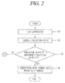
FIG. 2 is a flow chart illustrating an operation flow of a digital relay according to a preferred embodiment of the present disclosure; -
FIG. 3 is a flow chart illustrating a method of eliminating a harmonic wave noise or operation flow in a digital relay according to a preferred embodiment of the present disclosure; -
FIG. 4 is a waveform diagram illustrating a normal waveform of an electrical quantity detection signal in a digital relay according to a preferred embodiment of the present disclosure; and -
FIG. 5 is a waveform diagram illustrating a waveform of an electrical quantity detection signal subsequent to DFT processing in a digital relay according to a preferred embodiment of the present disclosure in which a normal waveform and a harmonic wave mixed waveform are shown together. - The objective of the present invention, as well as the configuration and working effect thereof to accomplish the foregoing objective will be more clearly understood by the following description for the preferred embodiments of present disclosure with reference to the accompanying drawings.
- First, the configuration of a digital relay according to a preferred embodiment of the present disclosure will be described with reference to
FIG. 1 . - Referring to
FIG. 1 , a digital relay according to a preferred embodiment of the present disclosure comprises an Analog-Digital Converter (abbreviated as ADC hereinafter) 22a, 22b and aprocessor 23. - The ADC 22a, 22b comprises a first ADC (ADC 0) 22a and a second ADC (ADC 1) 22b in
FIG. 1 . - Each of the
ADC - The
processor 23 can be configured with a microprocessor, and is a computing and processing unit configured to search an inflection point at which an electrical variation quantity varies from an increase to a decrease or from a decrease to an increase based on the digital signal, and determine the digital signal as an electrical disturbance to substitute electrical quantity data at the inflection point with normal electrical quantity data prior to a predetermined period (for instance, prior to one period) when an electrical variation quantity prior to and subsequent to the inflection point is not less than a predetermined normal reference electrical variation quantity. In other words, theprocessor 23 may include a program storage memory having an algorithm of searching an inflection point, an algorithm of determining an electrical disturbance and an algorithm of substituting with normal electrical quantity data, and a central processing unit of reading a processing algorithm from the relevant memory to perform the processing on the digital signal. - The
processor 23 is configured to perform a Discrete time Fourier Transform (hereinafter, abbreviated as "DFT") on the digital signal for a predetermined period of time, and compare a value at which the transformation value is increased and then converged with a predetermined normal convergence value (refer toFIG. 5 ), and determine it as a harmonic wave, namely, determine that a harmonic wave is mixed with an electrical quantity detection signal when the digital signal is determined as a harmonic wave when a difference between the converged value and the predetermined normal convergence value exceeds a predetermined difference, and perform root mean square (commonly referred to as "RMS") processing on the digital signal. In other words, theprocessor 23 may include a program storage memory having an algorithm of the DFT and comparing convergence values, an algorithm of determining harmonic wave mixing, and a root mean square processing algorithm, and a central processing unit for reading the relevant memory to perform the processing on a digital signal. -
FIG. 1 illustrates a digital relay including acontroller 20 according to a preferred embodiment of the present invention.Reference numeral 100 inFIG. 1 indicates a digital relay including thecontroller 20. - In
FIG. 1 , reference symbol IPhsA represents an A-phase (namely, R-pole) current detection signal of a 4-poles (4-phases) alternating current circuits, and reference character IPhsB represents an B-phase (namely, S-pole) current detection signal of the 4-poles (4-phases) alternating current circuits, and reference character IPhsC represents an C-phase (namely, T-pole) current detection signal of the 4-poles (4-phases) alternating current circuits, and reference character INeut represents an N-phase (namely, neutral pole) current detection signal of the 4-phases (4-poles) alternating current circuit. -
Reference numeral 10 designates a transformer unit for converting the current detection signal for each phase to a voltage signal with a small signal that can be processed by a digital circuit and a processor. -
Reference numeral 21a is a first multiplexer circuit unit for selectively providing any one of the four current detection signals for four phases, andreference numeral 21 b is a second multiplexer circuit unit for selectively providing any one of four voltage detection signals for four phases (not shown). -
Reference numeral 24 designates a driving circuit unit for driving a liquid crystal display, andreference numeral 25a designates a first input/output interface unit for inputting an input of a key switch and outputting an output signal(control signal) of a light emitting diode, andreference numeral 25b as an output interface circuit unit of a trip control signal of a circuit breaker, alarm signals output from adigital relay 100 designates a second input/output interface unit.Reference numeral 25c designates a third input/output interface unit for receiving digital input according to a selective manipulation of an input switch. -
Reference numeral 26 designates a universal asynchronous receiver transmitter (typically, can be abbreviated as a "UART") circuit unit, andreference numeral 27 designates a universal serial bus interface unit (namely, so called USB interface unit), andreference numeral 28 designates a real time clock for providing real time clock information, andreference numeral 29 designates a flash memory for storing a processing program or data, andreference numeral 30 designates a S-RAM for storing data during supplying of electric power. -
Reference numeral 31 designates a liquid crystal display as a display circuit unit, andreference numeral 32 designates a key switch and a light emitting diode as an input/output means, andreference numeral 33 designates a digital output port, andreference numeral 34 designates a digital input port, andreference numeral 35 designates a communication unit with a supervisory device such as an external remote monitoring apparatus (for example Supervisory Control and Data Acquisition system), andreference numeral 36 designates a USB port (universal serial bus port) capable of accessing a personal terminal capable of inputting and outputting data such as a keypad, andreference numeral 37 designates an output relay contacts, andreference numeral 38 designates an input switch unit. - The operation of the foregoing digital relay according to a preferred embodiment of the present invention and the foregoing noise elimination method of the foregoing digital relay according to a preferred embodiment of the present invention will be mainly described with reference to a flow chart, and supplementally described with reference to
FIGS. 1 ,4 and 5 . - Referring to
FIG. 2 , the first ADC (ADC 0) 22a in a digital relay according to a preferred embodiment of the present disclosure may sample a current detection signal (refer toFIG. 4 ) for each phase for a relay object (that is AC circuit as a monitoring target) and convert into a digital signal and provide the digital signal (sampling and analog-digital conversion step S1). - Then, the
processor 23 searches an inflection point at which an electrical variation quantity varies from an increase to a decrease or from a decrease to an increase based on the digital signal (inflection point search step S2). - Then, the
processor 23 compares an electrical variation quantity prior to and subsequent to the inflection point with a predetermined normal reference electrical variation quantity (variation quantity comparison step S3). - When an electrical variation quantity prior to and subsequent to the inflection point are not less than a predetermined normal reference electrical variation quantity during the variation quantity comparison step (S3), namely, when the electrical variation quantity prior to or subsequent to the inflection point is equal to or larger than a reference electrical variation quantity, the
processor 23 determines the digital signal as an electrical disturbance (namely, determines that a disturbance exists on the detected digital signal) to substitute electrical quantity data at the inflection point with electrical quantity data prior to a predetermined period (for instance, normal electrical quantity data prior to one period) (electrical disturbance elimination step S4). - When an electrical variation quantity prior to and subsequent to the inflection point are less than the predetermined normal reference electrical variation quantity during the variation quantity comparison step (S3), operation proceeds to the step S5 on a flow chart illustrated in
FIG. 3 to determine whether or not a harmonic wave is mixed therewith. - On the other hand, the present disclosure will be described with reference to
FIG. 3 , which is a flow chart illustrating a method of eliminating a harmonic wave noise or operation flow of an apparatus according to the present disclosure. - In order to check whether or not a harmonic wave is mixed with the detected electrical quantity signal, it is required to execute Discrete time Fourier Transform, namely, DFT, on digital signals sampled and entered through the first ADC (ADC 0) 22a for a predetermined period of time to compare a value at which the transformation value is increased and then converged with a normal convergence value as illustrated in
FIG. 5 . - When a harmonic wave is mixed with the detected electrical quantity signal, a convergence value is smaller compared to a normal convergence value. Accordingly, whether or not a harmonic wave is mixed with the electrical quantity signal can be determined using this characteristics.
- The
processor 23 executes DFT processing on the sampled and entered digital signals to determine whether or not a harmonic wave is mixed with the detected electrical quantity signal to compare the convergence value with a normal convergence value as illustrated inFIG. 5 (DFT conversion value comparison step S5). - When a difference between the converged value and the normal conversion value exceeds a predetermined difference during the DFT conversion value comparison step (S5), for instance, when a convergence value subsequent to DFT is less or greater than a predetermined difference compared to the normal convergence value, the
processor 23 determines that a harmonic wave is mixed with an electrical quantity detection signal and performs root mean square processing on the digital signal to eliminate harmonic wave noise (harmonic wave determination and processing step S6). - As described above, according to a digital relay according to the present disclosure or a noise elimination method thereof, an electrical variation quantity prior to and subsequent to an inflection point may be compared to a predetermined normal reference electrical variation quantity to determine the digital signal as an electrical disturbance when the electrical variation quantity prior to and subsequent to an inflection point is not less than the predetermined normal reference electrical variation quantity so as to substitute electrical quantity data at the inflection point with electrical quantity data prior to a predetermined period, thereby having an advantage capable of effectively eliminating a plurality of electrical disturbances even when mixed with an electrical quantity detection signal.
- According to a digital relay according to the present disclosure or a noise elimination method thereof, when a harmonic wave is mixed with an electrical quantity detection signal, the harmonic wave may be eliminated by root mean square processing, thereby providing an advantage capable of effectively eliminating harmonic wave noise.
Claims (6)
- A digital protective relay, characterized in that the digital protective relay comprising:a converter (22a, 22b) that samples an analog signal and converts a sampled analog signal to a digital signal; anda processor (23) that searches an inflection point at which an electrical variation quantity varies from an increase to a decrease or from a decrease to an increase based on the digital signal, and compares an electrical variation quantity prior to and subsequent to the inflection point with a preset electrical quantity.
- The digital protective relay of claim 1, wherein the processor (23) is configured to perform a Discrete Time Fourier Transform on the digital signal for a predetermined period of time, to compare a value at which a transformed value is increased and then converged with a predetermined normal convergence value, to determine the digital signal as a harmonic wave when a difference between the constantly converged transformed value and the predetermined normal convergence value exceeds a predetermined difference, and to determine the digital signal as an electrical disturbance when the difference between the constantly converged transformed value and the predetermined normal convergence value is larger or equal to a reference electrical variation quantity.
- The digital protective relay of claim 2, wherein the processor (23) is configured to perform a root mean square processing on the digital signal when the digital signal is determined as the harmonic wave.
- The digital protective relay of claim 2, wherein the processor (23) is configured to substitute an electrical quantity data at the inflection point with an electrical quantity data prior to a predetermined period when the digital signal is determined as the electrical disturbance.
- A noise elimination method for a digital relay, characterized in that the method comprising:a sampling and analog-digital conversion step that allows an analog-digital converter to sample an analog signal of an electrical quantity detection signal and convert a sampled analog signal to a digital signal;an inflection point search step that searches an inflection point at which an electrical variation quantity varies from an increase to a decrease or from a decrease to an increase based on the digital signal by a processor (23);a variation quantity comparison step that compares an electrical variation quantity prior to and subsequent to the inflection point with a predetermined normal reference electrical variation quantity by the processor (23); andan electrical disturbance elimination step that determines the digital signal as an electrical disturbance and substitutes an electrical quantity data at the inflection point with an electrical quantity data prior to a predetermined period by the processor (23) in case where an electrical variation quantity prior to and subsequent to the inflection point is not less than a predetermined normal reference electrical variation quantity during the variation quantity comparison step.
- The method of claim 5, further comprising:a Discrete Time Fourier Transform convergence value comparison step of performing a Discrete Time Fourier Transform on the digital signal for a predetermined period of time, and comparing a value at which the transformation value is increased and then converged with a predetermined normal convergence value by the processor (23); anda harmonic wave determination and processing step of determining that a harmonic wave is mixed with an electrical quantity detection signal to perform root mean square processing on the digital signal when a difference between the converged value and the normal convergence value exceeds a predetermined difference during the Discrete Time Fourier Transform convergence value comparison step.
Applications Claiming Priority (1)
| Application Number | Priority Date | Filing Date | Title |
|---|---|---|---|
| KR1020150018839A KR102006186B1 (en) | 2015-02-06 | 2015-02-06 | Digital protective relay |
Publications (1)
| Publication Number | Publication Date |
|---|---|
| EP3054546A1 true EP3054546A1 (en) | 2016-08-10 |
Family
ID=55236212
Family Applications (1)
| Application Number | Title | Priority Date | Filing Date |
|---|---|---|---|
| EP16152272.7A Withdrawn EP3054546A1 (en) | 2015-02-06 | 2016-01-21 | Digital protective relay |
Country Status (4)
| Country | Link |
|---|---|
| US (1) | US9755656B2 (en) |
| EP (1) | EP3054546A1 (en) |
| KR (1) | KR102006186B1 (en) |
| CN (1) | CN105870890B (en) |
Families Citing this family (3)
| Publication number | Priority date | Publication date | Assignee | Title |
|---|---|---|---|---|
| KR101770926B1 (en) * | 2016-12-30 | 2017-08-23 | 엘에스산전 주식회사 | Method for detecting electrical disturbances by DC component |
| US20230068467A1 (en) * | 2019-11-12 | 2023-03-02 | Nippon Telegraph And Telephone Corporation | Monitoring system, monitoring method, agent program and manager program |
| KR102739889B1 (en) * | 2023-04-14 | 2024-12-10 | 엘에스일렉트릭(주) | Relay and control method of the relay |
Citations (5)
| Publication number | Priority date | Publication date | Assignee | Title |
|---|---|---|---|---|
| KR0146088B1 (en) | 1995-03-07 | 1998-10-01 | 이희종 | Digital protection relay |
| US20060203401A1 (en) * | 2005-03-11 | 2006-09-14 | Honeywell International Inc. | Method and apparatus for generalized arc fault detection |
| KR20100101980A (en) * | 2009-03-10 | 2010-09-20 | 엘에스산전 주식회사 | Apparatus and method for detecting data validity |
| EP2355288A2 (en) * | 2010-01-27 | 2011-08-10 | LS Industrial Systems Co., Ltd | Device and method for processing input data of protective relay |
| US20120126771A1 (en) * | 2010-11-21 | 2012-05-24 | Qualcomm Incorporated | Circuitry for detecting a transient |
Family Cites Families (8)
| Publication number | Priority date | Publication date | Assignee | Title |
|---|---|---|---|---|
| EP0910908A1 (en) * | 1996-07-10 | 1999-04-28 | Lecroy Corporation | Method and system for characterizing terminations in a local area network |
| KR100276397B1 (en) * | 1997-12-30 | 2001-01-15 | 권상문 | Digital relay speeds up phase loss protection by using frequency multiplication |
| US7936549B2 (en) * | 2004-05-13 | 2011-05-03 | Mitsubishi Electric Corporation | State grasp device, and switching control device of power switching apparatus employing the state grasp device |
| JP4908018B2 (en) * | 2006-02-28 | 2012-04-04 | 株式会社東芝 | Current differential relay device, signal processing method thereof, and transmission line protection system |
| KR100940313B1 (en) * | 2008-06-19 | 2010-02-04 | 주식회사 효성 | Digital protective relay with extended self-monitoring function and its malfunction prevention method |
| CN101494374B (en) * | 2009-03-04 | 2010-09-08 | 南京因泰莱配电自动化设备有限公司 | Current protection control method for vacuum circuit breaker |
| CN101702506B (en) * | 2009-10-30 | 2012-05-30 | 中国船舶重工集团公司第七一九研究所 | Method and device for rapidly detecting short-circuit fault of power system |
| US9250283B2 (en) * | 2011-06-17 | 2016-02-02 | Psiber Data Systems, Inc | System and method for automated testing of an electric cable harness |
-
2015
- 2015-02-06 KR KR1020150018839A patent/KR102006186B1/en active Active
-
2016
- 2016-01-21 EP EP16152272.7A patent/EP3054546A1/en not_active Withdrawn
- 2016-01-21 US US15/003,728 patent/US9755656B2/en active Active
- 2016-02-04 CN CN201610080623.3A patent/CN105870890B/en active Active
Patent Citations (5)
| Publication number | Priority date | Publication date | Assignee | Title |
|---|---|---|---|---|
| KR0146088B1 (en) | 1995-03-07 | 1998-10-01 | 이희종 | Digital protection relay |
| US20060203401A1 (en) * | 2005-03-11 | 2006-09-14 | Honeywell International Inc. | Method and apparatus for generalized arc fault detection |
| KR20100101980A (en) * | 2009-03-10 | 2010-09-20 | 엘에스산전 주식회사 | Apparatus and method for detecting data validity |
| EP2355288A2 (en) * | 2010-01-27 | 2011-08-10 | LS Industrial Systems Co., Ltd | Device and method for processing input data of protective relay |
| US20120126771A1 (en) * | 2010-11-21 | 2012-05-24 | Qualcomm Incorporated | Circuitry for detecting a transient |
Also Published As
| Publication number | Publication date |
|---|---|
| US9755656B2 (en) | 2017-09-05 |
| CN105870890A (en) | 2016-08-17 |
| CN105870890B (en) | 2018-08-03 |
| KR20160097037A (en) | 2016-08-17 |
| KR102006186B1 (en) | 2019-08-01 |
| US20160233876A1 (en) | 2016-08-11 |
Similar Documents
| Publication | Publication Date | Title |
|---|---|---|
| US11557450B2 (en) | Method for diagnosing the cause of tripping of an electrical protection device, auxiliary device and electrical system for implementing such a method | |
| EP3496222B1 (en) | Earth leakage circuit breaker based on the ratio of a specific harmonic current component to the fundamental wave current component | |
| US20030072113A1 (en) | Arc detection using load recognition, harmonic content and broadband noise | |
| US20200319262A1 (en) | Time Domain Distance Protection Based on Polarity Comparison for Power Transmission Lines | |
| US9755656B2 (en) | Digital protective relay | |
| WO2020011740A1 (en) | Ground fault detection circuit and device | |
| US10522995B2 (en) | Overcurrent element in time domain | |
| MX2009002646A (en) | Apparatus, systems and methods for reliably detecting faults within a power distribution system. | |
| US8045307B2 (en) | Faulted phase decision method between current and voltage based delta phase selectors | |
| CN106257294A (en) | For the method and apparatus detecting the fault in electrical network | |
| EP3678270A1 (en) | Digital protection relay and threshold learning method of digital protection relay | |
| JPS62110168A (en) | Digital trouble point locating apparatus | |
| KR101770926B1 (en) | Method for detecting electrical disturbances by DC component | |
| US10845427B2 (en) | Method for detecting earth-fault conditions in a power conversion apparatus | |
| CN117310358B (en) | Neutral line or phase loss detection | |
| EP3795966A1 (en) | Circuit interrupter and method of estimating a temperature of a busbar in a circuit interrupter | |
| KR101377190B1 (en) | Phase identification appratus and method of of leakage and arc on switchgear | |
| US11411390B2 (en) | Secure and dependable restricted earth fault protection for electric power generators and transformers | |
| US10310017B2 (en) | Detection of generator stator inter-circuit faults | |
| RU2657290C1 (en) | Automated system of diagnosing and monitoring the insulation of power cable lines | |
| RU2732000C1 (en) | Automated control system of state of power cable lines insulation and mode of unstable earth faults | |
| CN118679395A (en) | Phase selection method | |
| KR20130092803A (en) | Merging unit with frequency protection function | |
| US10474142B2 (en) | Detection of cross-country faults | |
| US20240072697A1 (en) | Split-phase protection of generators |
Legal Events
| Date | Code | Title | Description |
|---|---|---|---|
| PUAI | Public reference made under article 153(3) epc to a published international application that has entered the european phase |
Free format text: ORIGINAL CODE: 0009012 |
|
| AK | Designated contracting states |
Kind code of ref document: A1 Designated state(s): AL AT BE BG CH CY CZ DE DK EE ES FI FR GB GR HR HU IE IS IT LI LT LU LV MC MK MT NL NO PL PT RO RS SE SI SK SM TR |
|
| AX | Request for extension of the european patent |
Extension state: BA ME |
|
| STAA | Information on the status of an ep patent application or granted ep patent |
Free format text: STATUS: REQUEST FOR EXAMINATION WAS MADE |
|
| 17P | Request for examination filed |
Effective date: 20170209 |
|
| RBV | Designated contracting states (corrected) |
Designated state(s): AL AT BE BG CH CY CZ DE DK EE ES FI FR GB GR HR HU IE IS IT LI LT LU LV MC MK MT NL NO PL PT RO RS SE SI SK SM TR |
|
| STAA | Information on the status of an ep patent application or granted ep patent |
Free format text: STATUS: EXAMINATION IS IN PROGRESS |
|
| 17Q | First examination report despatched |
Effective date: 20180807 |
|
| STAA | Information on the status of an ep patent application or granted ep patent |
Free format text: STATUS: THE APPLICATION IS DEEMED TO BE WITHDRAWN |
|
| 18D | Application deemed to be withdrawn |
Effective date: 20220802 |