EP3054545A1 - Flexible, pressure-balanced cable assembly - Google Patents
Flexible, pressure-balanced cable assembly Download PDFInfo
- Publication number
- EP3054545A1 EP3054545A1 EP16152201.6A EP16152201A EP3054545A1 EP 3054545 A1 EP3054545 A1 EP 3054545A1 EP 16152201 A EP16152201 A EP 16152201A EP 3054545 A1 EP3054545 A1 EP 3054545A1
- Authority
- EP
- European Patent Office
- Prior art keywords
- flexible
- electrical cable
- pressure
- seals
- assembly
- Prior art date
- Legal status (The legal status is an assumption and is not a legal conclusion. Google has not performed a legal analysis and makes no representation as to the accuracy of the status listed.)
- Withdrawn
Links
- 239000012530 fluid Substances 0.000 claims abstract description 38
- 239000004020 conductor Substances 0.000 claims description 56
- 238000000034 method Methods 0.000 claims description 15
- 238000004891 communication Methods 0.000 claims description 10
- 239000004033 plastic Substances 0.000 claims description 10
- 229920003023 plastic Polymers 0.000 claims description 10
- 238000000638 solvent extraction Methods 0.000 claims description 2
- 238000005192 partition Methods 0.000 abstract description 2
- 239000004519 grease Substances 0.000 description 5
- 239000000463 material Substances 0.000 description 5
- 239000002184 metal Substances 0.000 description 5
- 229910052751 metal Inorganic materials 0.000 description 5
- RYGMFSIKBFXOCR-UHFFFAOYSA-N Copper Chemical compound [Cu] RYGMFSIKBFXOCR-UHFFFAOYSA-N 0.000 description 4
- 230000000712 assembly Effects 0.000 description 3
- 238000000429 assembly Methods 0.000 description 3
- 239000007788 liquid Substances 0.000 description 3
- 229920001169 thermoplastic Polymers 0.000 description 3
- 239000004416 thermosoftening plastic Substances 0.000 description 3
- 229920002943 EPDM rubber Polymers 0.000 description 2
- 239000004677 Nylon Substances 0.000 description 2
- 229910052802 copper Inorganic materials 0.000 description 2
- 239000010949 copper Substances 0.000 description 2
- 230000008878 coupling Effects 0.000 description 2
- 238000010168 coupling process Methods 0.000 description 2
- 238000005859 coupling reaction Methods 0.000 description 2
- 238000010586 diagram Methods 0.000 description 2
- 150000002739 metals Chemical class 0.000 description 2
- 229920001778 nylon Polymers 0.000 description 2
- 239000003129 oil well Substances 0.000 description 2
- 230000003287 optical effect Effects 0.000 description 2
- 229920001343 polytetrafluoroethylene Polymers 0.000 description 2
- 239000004810 polytetrafluoroethylene Substances 0.000 description 2
- 230000002939 deleterious effect Effects 0.000 description 1
- 230000001419 dependent effect Effects 0.000 description 1
- 238000005516 engineering process Methods 0.000 description 1
- 239000007789 gas Substances 0.000 description 1
- 238000004519 manufacturing process Methods 0.000 description 1
- 229920001296 polysiloxane Polymers 0.000 description 1
- -1 polytetrafluoroethylene Polymers 0.000 description 1
- 229920003051 synthetic elastomer Polymers 0.000 description 1
- 239000005061 synthetic rubber Substances 0.000 description 1
Images



Classifications
-
- H—ELECTRICITY
- H01—ELECTRIC ELEMENTS
- H01B—CABLES; CONDUCTORS; INSULATORS; SELECTION OF MATERIALS FOR THEIR CONDUCTIVE, INSULATING OR DIELECTRIC PROPERTIES
- H01B7/00—Insulated conductors or cables characterised by their form
- H01B7/04—Flexible cables, conductors, or cords, e.g. trailing cables
-
- H—ELECTRICITY
- H01—ELECTRIC ELEMENTS
- H01B—CABLES; CONDUCTORS; INSULATORS; SELECTION OF MATERIALS FOR THEIR CONDUCTIVE, INSULATING OR DIELECTRIC PROPERTIES
- H01B13/00—Apparatus or processes specially adapted for manufacturing conductors or cables
- H01B13/22—Sheathing; Armouring; Screening; Applying other protective layers
- H01B13/221—Sheathing; Armouring; Screening; Applying other protective layers filling-up interstices
-
- H—ELECTRICITY
- H02—GENERATION; CONVERSION OR DISTRIBUTION OF ELECTRIC POWER
- H02G—INSTALLATION OF ELECTRIC CABLES OR LINES, OR OF COMBINED OPTICAL AND ELECTRIC CABLES OR LINES
- H02G1/00—Methods or apparatus specially adapted for installing, maintaining, repairing or dismantling electric cables or lines
- H02G1/14—Methods or apparatus specially adapted for installing, maintaining, repairing or dismantling electric cables or lines for joining or terminating cables
-
- H—ELECTRICITY
- H02—GENERATION; CONVERSION OR DISTRIBUTION OF ELECTRIC POWER
- H02G—INSTALLATION OF ELECTRIC CABLES OR LINES, OR OF COMBINED OPTICAL AND ELECTRIC CABLES OR LINES
- H02G15/00—Cable fittings
- H02G15/02—Cable terminations
- H02G15/04—Cable-end sealings
- H02G15/043—Cable-end sealings with end caps, e.g. sleeve closed at one end
- H02G15/046—Cable-end sealings with end caps, e.g. sleeve closed at one end with bores or protruding portions allowing passage of cable conductors
-
- H—ELECTRICITY
- H02—GENERATION; CONVERSION OR DISTRIBUTION OF ELECTRIC POWER
- H02G—INSTALLATION OF ELECTRIC CABLES OR LINES, OR OF COMBINED OPTICAL AND ELECTRIC CABLES OR LINES
- H02G15/00—Cable fittings
- H02G15/08—Cable junctions
- H02G15/18—Cable junctions protected by sleeves, e.g. for communication cable
-
- E—FIXED CONSTRUCTIONS
- E21—EARTH OR ROCK DRILLING; MINING
- E21B—EARTH OR ROCK DRILLING; OBTAINING OIL, GAS, WATER, SOLUBLE OR MELTABLE MATERIALS OR A SLURRY OF MINERALS FROM WELLS
- E21B17/00—Drilling rods or pipes; Flexible drill strings; Kellies; Drill collars; Sucker rods; Cables; Casings; Tubings
- E21B17/02—Couplings; joints
- E21B17/028—Electrical or electro-magnetic connections
-
- H—ELECTRICITY
- H02—GENERATION; CONVERSION OR DISTRIBUTION OF ELECTRIC POWER
- H02G—INSTALLATION OF ELECTRIC CABLES OR LINES, OR OF COMBINED OPTICAL AND ELECTRIC CABLES OR LINES
- H02G1/00—Methods or apparatus specially adapted for installing, maintaining, repairing or dismantling electric cables or lines
- H02G1/06—Methods or apparatus specially adapted for installing, maintaining, repairing or dismantling electric cables or lines for laying cables, e.g. laying apparatus on vehicle
- H02G1/08—Methods or apparatus specially adapted for installing, maintaining, repairing or dismantling electric cables or lines for laying cables, e.g. laying apparatus on vehicle through tubing or conduit, e.g. rod or draw wire for pushing or pulling
-
- H—ELECTRICITY
- H02—GENERATION; CONVERSION OR DISTRIBUTION OF ELECTRIC POWER
- H02G—INSTALLATION OF ELECTRIC CABLES OR LINES, OR OF COMBINED OPTICAL AND ELECTRIC CABLES OR LINES
- H02G15/00—Cable fittings
- H02G15/20—Cable fittings for cables filled with or surrounded by gas or oil
- H02G15/22—Cable terminations
- H02G15/23—Cable-end sealings
-
- H—ELECTRICITY
- H02—GENERATION; CONVERSION OR DISTRIBUTION OF ELECTRIC POWER
- H02G—INSTALLATION OF ELECTRIC CABLES OR LINES, OR OF COMBINED OPTICAL AND ELECTRIC CABLES OR LINES
- H02G15/00—Cable fittings
- H02G15/20—Cable fittings for cables filled with or surrounded by gas or oil
- H02G15/24—Cable junctions
Definitions
- aspects described herein relate to a pressure-balanced cable assembly that utilizes a tubular-shaped flexible sleeve surrounding an electrical cable.
- a series of O-ring seals are positioned between an inner surface of the flexible sleeve and an outer surface of the electrical cable and dielectric fluid is distributed between each of the O-rings.
- Each adjacent pair of O-ring seals delimits and seals an individual chamber containing the dielectric fluid.
- the O-ring seals are independently and bi-directionally movable along the electrical cable in response to differences in pressure between the environment external to the assembly (e.g. , the downhole environment) and pressures within the assembly.
- the use of multiple O-ring seals provides a high degree of redundancy in the case that one or more of the O-rings fail. The result is an inexpensive, flexible, low-profile pressure-balanced cable assembly that has a high degree of reliability.
- a flexible, pressure-balanced sleeve assembly for a cable termination.
- the sleeve assembly comprises a flexible outer sleeve surrounding an electrical cable, a plurality of seals positioned between the flexible outer sleeve and the electrical cable, and a plurality of chambers defined between each of the plurality of seals.
- Dielectric fluid is contained within each of the plurality of chambers.
- the seals are independently movable along the electrical cable in response to differences between a pressure within a respective chamber and a pressure outside of the respective chamber.
- a flexible, pressure-balanced electrical cable assembly comprises an electrical cable and a flexible tubing positioned over the electrical cable.
- the flexible tubing defines a space between an inner surface of the flexible tubing and an outer surface of the electrical cable.
- a plurality of O-ring seals is positioned between the inner surface of the flexible tubing and the outer surface of the electrical cable where the plurality of O-ring seals partition the space into a plurality of individual chambers.
- the assembly further comprises dielectric fluid contained within each of the individual chambers.
- Each of the plurality of O-ring seals is independently movable along the outer surface of the electrical cable in response to differences between a pressure within the electrical cable assembly and a pressure outside of the assembly.
- a method of pressure-balancing a termination of an electrical cable comprises positioning the electrical cable within a flexible outer sleeve where a space is defined between an outer surface of the electrical cable and an inner surface of the flexible outer sleeve.
- a plurality of O-ring seals is positioned in the space.
- Positioning the O-ring seals comprises spacing apart each O-ring seal along a length of the flexible outer sleeve and distributing dielectric fluid between each of the plurality of O-ring seals during the positioning step.
- Each adjacent pair of O-ring seals delimits and seals an individual chamber containing the dielectric fluid.
- the assembly comprises a flexible outer sleeve constructed from, for example, a non-electrically conductive plastic that surrounds an electrical cable.
- the flexible outer sleeve defines a chamber or space between an inner surface of the outer sleeve and an outer surface of the electrical cable.
- O-ring seals are positioned within the space effectively partitioning the space into a plurality of discrete chambers. Each of the discrete chambers is filled with a dielectric fluid.
- each of the O-ring seals is independently and bi-directionally movable along the electrical cable to effectuate pressure-balancing between the external and the internal environment.
- the flexible, pressure-balanced cable assembly thus described provides an economical alternative to traditional pressure-balanced assemblies constructed from multiple metal parts.
- the outside diameter of the flexible, pressure-balanced cable assembly may be configured to be only slightly greater than the diameter of the electrical cable itself.
- the resulting low-profile of the assembly combined with the flexible nature of the outer sleeve, makes the assembly easy to manipulate when used in, for example, a downhole oil well environment.
- the use of multiple O-ring seals provides layers of redundancy which, in turn, imparts a high degree of reliability to the flexible, pressure-balanced cable assembly.
- the term "flexible” when used in the context of the outer sleeve may be defined as the capability to bend easily without comprising the integrity of the outer sleeve.
- the term “cable” may mean a single electrical, or optical, conductor or it may mean two or more separate electrical or optical conductors joined together via, for example, a contact socket or other type of connection.
- distal as used throughout this disclosure means further away from a defined midpoint, while the term “proximal” means closer to the defined midpoint.
- the cable assembly 100 comprises at least an electrical cable 105 (shown as a first conductor 110 and a second conductor 112 connected by a contact socket 120) surrounded by a flexible sleeve 114.
- Multiple seals 116 are spaced along the length of the flexible sleeve 114 and are disposed in an annular chamber or space 118 created by an inner surface of the tubular-shaped flexible sleeve 114 and an outer surface of the first conductor 110 and the second conductor 112.
- the annular space 118 is divided into a series of individual chambers 119 by the seals 116 with each individual chamber 119 delimited and sealed by an adjacent pair of the seals 116.
- Each of the chambers 119 is filled with a dielectric silicone grease or other dielectric fluid. The dielectric fluid helps to protect the electrical cable 105 from the deleterious effects of gases and/or liquids in the downhole environment.
- the electrical cable 105 comprising the first conductor 110 and the second conductor 112 may comprise a copper conductor core 128 surrounded by, for instance, an ethylene propylene diene monomer (EPDM) insulative shield 126.
- the contact socket 120 is configured to receive the terminal end of the conductor 110 and the terminal end of the conductor 112 and to electrically and mechanically couple the two conductors 110 and 112 together. Other ways of mechanically and electrically coupling the two conductors 110 and 112 are contemplated herein.
- the tubular-shaped flexible sleeve 114 is constructed from a plastic material such as, for example, perfluroalkoxy (PFA), monofluoroalkoxy (MFA), polytetrafluoroethylene (PTFE), and other similar plastics.
- PFA perfluroalkoxy
- MFA monofluoroalkoxy
- PTFE polytetrafluoroethylene
- the material selected to form the flexible sleeve 114 should generally be rated to a high temperature and have a high dielectric strength such that the material is substantially non-electrically conductive.
- the sleeve 114 may have an outside diameter in the range of, for example, 13 mm to 19 mm although other diameters are contemplated as being within the scope herein.
- the thickness of the sleeve 114 (e.g ., the difference between the outside diameter and the inside diameter of the flexible sleeve 114) may vary but is generally in the range of 2.00 mm to 3.00 mm.
- the length of the flexible sleeve 114 may be variable but should generally be such that it extends a predetermined distance along the conductors 110/112 starting from a midpoint of the contact socket 120.
- the seals 116 may comprise O-ring formed from, for example, synthetic rubbers or plastics including thermoplastics.
- the O-rings may be circular-shaped and/or may have other shapes such as a square or a quad-type O-ring seal.
- the size of the O-ring is dependent on the dimensions associated with the sleeve 114 and the dimensions of the conductors 110/112.
- the inside diameter of the O-ring should be approximately the same as the outside diameter of the conductors 110/112, and the outside diameter of the O-ring should be approximately the same as the inside diameter of the flexible sleeve 114 so that the O-ring occupies substantially all the space 118 between the outer surface of the conductors 110/112 and the inner surface of the flexible sleeve 114 leaving no gaps.
- the outside diameter of the O-ring may be slightly greater than the inside diameter of the flexible sleeve 114 so as to form an even more occlusive seal.
- the inside diameter of the O-ring may be slightly less than the outside diameter of the electrical cable 105.
- the number of seals 116 may range from a minimum of 2 up to, for example, 20, with an equal number of seals generally being positioned on either side of the midpoint of the contact socket 120.
- the number of seals 116 and the amount of space 118 between the outside surface of the electrical cable 105 and the inside surface of the flexible sleeve 114 will determine the number and size of the chambers 119.
- the number and size of the chambers 119 in turn, will determine the volume of dielectric fluid within the cable assembly 100.
- the dimensions of the flexible sleeve 114 and the dimensions of the seals 116 may be adjusted so as to maintain a fairly consistent volume of dielectric fluid within the cable assembly 100 in order to achieve adequate protection for the electrical cable 105.
- the flexible sleeve 114 may be selected to have an outside diameter that is only slightly greater than the diameter of the electrical cable 105. Assuming the thickness of the sleeve 114 is constant, this reduces the amount of space 118 between the inner surface of the flexible sleeve 114 and the outer surface of the electrical cable 105.
- the length of the flexible sleeve 114 may be increased and a greater number of seals 116 having a smaller outside diameter may be utilized to create a greater number of chambers 119.
- the flexible sleeve 114 may be selected to have a larger outside diameter. Again assuming the thickness of the flexible sleeve 114 remains the same, there will be a greater amount of space 118 between the inner surface of the flexible sleeve 114 and the outer surface of the electrical cable 105. In this situation, a fewer number of seals 116 having a larger outside diameter may be utilized to create a fewer number of chambers 119 having a larger volume such that the total quantity of dielectric fluid remains the same.
- the seals 116 are adapted to be bi-directionally and independently movable along the outer surface of the electrical cable 105 and the inner surface of the flexible sleeve 114 in response to pressure differentials between the interior of the cable assembly 100 and the external environment. More specifically, the inside diameter of the seals 116 is in direct contact with the outer surface of the insulative shield 126 and translates along the surface of the insulative shield 126 in response to the pressure differential. Further, the outside diameter of the seals 116 is in direct contact with the inner surface of the flexible sleeve 114 and translates along inner surface of the flexible sleeve 114 in response to the pressure differential.
- a lower overall outside diameter of the cable assembly 100 may be achieved as opposed to pressure-balancing assemblies that rely on multiple, metal machined parts and/or shuttles to achieve pressure balancing.
- FIG. 1B depicts a cross-sectional view of the assembly 100 taken along line 1B-1B of FIG. 1A.
- FIG. 1B depicts the flexible sleeve 114 surrounding the electrical cable 105 comprising the copper conductor core 128 surrounded by the insulative shield 126.
- the space defined by the inner surface of the flexible sleeve 114 and the outer surface of the insulative shield 126 is occupied by the O-ring seal 116. More specifically, an inner surface of the seal 116 having an inside diameter 136 rests against the outer surface of the insulative shield 126, and the outer surface of the seal 116 having an outside diameter 134 rests against the inner surface of the flexible sleeve 114, where the inner surface has an inside diameter 132.
- the outer diameter 134 of the seal 116 is generally equal to the inside diameter 132 of the sleeve 114.
- FIG. 1B further depicts the outer surface of the flexible sleeve 114 having an outside diameter 130.
- FIG. 1C depicts a cross-sectional view of the cable assembly 100 taken along line 1C-1C of FIG. 1A .
- This section of the assembly 100 does not contain a seal 116. Instead, as shown in FIG. 1C , a chamber 119 is defined between the inner surface of the flexible sleeve 114 and the outer surface of the insulative shield 126.
- the chamber 119 is filled with a dielectric fluid as shown by the bubbles in the chamber 119.
- the cable assembly 100 may optionally comprise a first fitting 122 and a second fitting 124 disposed at a first end and a second end of the flexible sleeve 114 respectively.
- the fittings 122 and 124 are not required for the cable assembly 100 to perform its pressure-balancing function but may be useful to facilitate assembly of the cable assembly 100 and/or to mechanically couple the assembly 100 to other equipment as will be explained below.
- FIG. 2 depicts a close-up cross-sectional view of the first fitting 122 taken along its longitudinal axis in accordance with an aspect herein.
- the first fitting 122 is tubular shaped and is attached to a first end 205 of the flexible sleeve 114.
- the first fitting 122 surrounds the first conductor 110, and an annular cavity 212 is formed between the inner surface of the tubular-shaped first fitting 122 and the outer surface of the conductor 110.
- the annular cavity 212 is in communication with the space 118 created by the inner surface of the flexible sleeve 114, and the outer surface of the conductor 110.
- the first fitting 122 may be formed from materials comprising metals, plastics, thermoplastics, nylon or any combination thereof.
- the first fitting 122 comprises a first portion 214, a second portion 216, and an intervening portion 218 connecting the first portion 214 with the second portion 216.
- the first portion 214 may comprise a threaded fill port 220 that is in communication with the environment external to the cable assembly 100 and the interior of the cable assembly 100.
- the fill port 220 provides a communication path from the external environment (e.g. , the downhole environment) through the fill port 220, into the annular cavity 212 and up to the first seal 116 located in the space 118 between the outer surface of the conductor 110 and the inner surface of the flexible sleeve 114.
- any changes in pressure - whether positive or negative - are effectively communicated to the interior of the cable assembly 100 where the change in pressure can be balanced via movement of the seals 116 along the flexible sleeve 114/electrical cable 105.
- the first seal 116 shown in FIG. 2 prevents any harmful liquids or fluids from the downhole environment from coming into contact with the connection between the first conductor 110 and the second conductor 112 at the contact socket 120.
- a grease gun may be connected to the fill port 220 and dielectric fluid or grease can be distributed into the space 118 via the fill port 220. This process will be explained in greater depth below with respect to FIGs. 5-7 .
- the first portion 214 may further comprise a seal 222 located distal to the fill port 220 ( i.e ., further away from the midpoint of the contact socket 120).
- the seal 222 may be used to prevent any dielectric fluid inserted via the fill port 220 from escaping the assembly 100.
- the first portion 214 may also be adapted to be attached to other devices used in downhole environments such as, for example, an electric submersible pump (ESP).
- ESP electric submersible pump
- the second portion 216 of the first fitting 122 comprises a series of barbs 224 that are adapted to mechanically couple the first fitting 122 to the first end 205 of the flexible sleeve 114 by engaging the inner surface of the flexible sleeve 114.
- the intervening portion 218 has a smooth outer surface. When assembling the cable assembly 100, the seals 116 may first be loaded onto the intervening portion 218 prior to being positioned along the length of the flexible sleeve 114. To put it another way, the intervening portion 218 may act to retain the seals 116 prior to assembling the cable assembly 100.
- the length of the intervening portion 218 may be configurable based on the number of seals 116 to be positioned along the length of the flexible sleeve 114 - the greater number of seals 116, the longer the intervening portion 218, and the lesser number of seals 116, the shorter the length of the intervening portion 218.
- FIG. 4 depicts a close-up cross-sectional view of the second fitting 124 taken along its longitudinal axis.
- the second fitting 124 is tubular shaped and is attached to a second end 405 of the flexible sleeve 114.
- the second fitting 124 surrounds the second conductor 112, and an annular cavity 416 is formed between the inner surface of the tubular-shaped second fitting 124 and the outer surface of the conductor 112.
- the annular cavity 416 is in communication with the space 118 created by the inner surface of the flexible sleeve 114 and the outer surface of the conductor 112.
- the second fitting 124 may be formed from materials comprising metals, plastics, thermoplastic, nylon or any combination thereof.
- the second fitting 124 comprises a first portion 410, a second portion 412, and an intervening portion 414 that connects the first portion 410 to the second portion 412.
- the first portion 410 comprises an open port hole 418 that is in communication with the external environment and the annular cavity 416. Similar to the fill port 220 of the first fitting 122, the port hole 418 acts to convey pressure differences - whether positive or negative - between the external environment and the interior of the cable assembly 100, where the pressure differences are balanced via movement of the seals 116 along the flexible sleeve 114/electrical cable 105.
- the first portion 410 may further comprise a seal 420 located distal ( i . e ., further away from the midpoint of the contact socket 120) to the port hole 418.
- the seal 420 acts to prevent loss of dielectric fluid from the assembly 100.
- the first portion 410 may also be adapted to be attached to other devices used in downhole environments.
- the second portion 412 of the second fitting 124 comprises a series of barbs 422 that are adapted to mechanically engage with the inner surface of the second end 405 of the flexible sleeve 114.
- the length of the intervening portion 414 of the second fitting 124 may be less than that of the intervening portion 218 of the first fitting 122. This is generally because, in an exemplary aspect, the second fitting 124 may not be used to load/retain the seals 116 when assembling the cable assembly 100.
- the cable assembly 100 may optionally comprise a coil spring located at each end of the cable assembly 100 to achieve a slightly higher pressure bias within the assembly 100 as compared to the external environment.
- a slightly higher pressure bias within the assembly 100 a failure of one or more of the seals 116 will cause dielectric fluid to exit the assembly 100 instead of fluids from the downhole environment entering the assembly 100 and potentially causing an electrical short.
- the cable assembly 100 may be configured such that the flexible sleeve 114 is positioned over just the electrical cable 110 and a bulkhead pressure block connector is used to connect the electrical cable 112 to the electrical cable 110. This same configuration holds true if the flexible sleeve 114 is positioned over just the electrical cable 112. Any and all such aspects, and any variation thereof, are contemplated as being within the scope herein.
- FIGs. 5 and 6 illustrate aspects of how the seals 116 are loaded onto the cable assembly 100 in one exemplary aspect.
- the loading process may occur off-site (e.g. , at a manufacturing site) or on-site (e.g. , at the downhole oil well environment).
- FIG. 5 depicts a side elevation view of the first fitting 122 unaffixed to the flexible sleeve 114 of the cable assembly 100.
- FIG. 5 illustrate a number of seals 116 loaded on to the intervening portion 218. This may occur by loading the seals 116 onto a terminal end 510 of the second portion 216, sliding them over the barbs 224, and sliding them along the intervening portion 218.
- the loading of the seals 116 may occur via a manual or an automated process.
- FIG. 6 depicts a cross-sectional view of the cable assembly 100 taken along its longitudinal axis after the seals 116 have been loaded on to the first fitting 122 but prior to the seals 116 being positioned along the length of the flexible sleeve 114.
- the first conductor 110 is coupled to the second conductor 112 via the contact socket 120 and the flexible sleeve 114 is positioned over the conductors 110/112 and the contact socket 120 prior to the seals 116 being positioned along the length of the flexible sleeve 114.
- One exemplary process for positioning the seals 116 along the length of the flexible sleeve 114 comprises unloading a first seal 610 from the second portion 216 of the first fitting 122 by, for example, pulling the first seal 610 over the barbs 224 and positioning the seal 610 at the terminal end 510 of the second portion 216, and then coupling the first fitting 122 to the first end 205 of the flexible sleeve 114 via the barbs 224.
- a grease gun can then be fitted into the fill port 220 and a redefined quantity of dielectric fluid may be inserted into the annular cavity 212.
- distribution of dielectric fluid into the annular cavity 212 acts to move the first seal 610 a predetermined distance in the space 118 created by the inner surface of the flexible sleeve 114 and the outer surface of the electrical cable 105.
- the first fitting 122 may be disengaged from the flexible sleeve 114, and a second seal 116 may be moved from the intervening portion 218, over the barbs 224, and on to the terminal end 510.
- the first fitting 122 is then re-coupled with the flexible sleeve 114 and dielectric grease is again inserted via the fill port 220 until the second seal 116 moves a predetermined distance in the space 118 created by the inner surface of the flexible sleeve 114 and the outer surface of the electrical cable 105.
- the process is repeated until all of the seals 116 have been positioned along the length of the first conductor 110 and the second conductor 112 and dielectric fluid fills each chamber 119 created by each adjacent pair of seals 116.
- the first conductor 110 may not yet be coupled to the second conductor 112 via the contact socket 120, and the flexible sleeve 114 may be positioned just over the first conductor 110.
- the seals 116 may be positioned along a substantial portion of the length of the first conductor 110 using the process set forth above.
- the contact socket 120 may then be used to couple the first conductor 110 to the second conductor 112.
- the flexible sleeve 114 may then be slid over the second conductor 112 until the midpoint of the flexible sleeve 114 is generally positioned over the midpoint of the contact socket 120 and an equal number of seals 116 are generally positioned on either side of the midpoint of the contact socket 120.
- FIG. 8 depicts a cross-sectional view 800 of a T-shaped fitting 810 taken along its longitudinal axis.
- the two arms of the tubular-shaped fitting 810 are coupled to a first end of a first flexible sleeve 812 and a first end of a second flexible sleeve 814 by barbs, where both the first and second sleeves 812 and 814 surround an electrical cable 816.
- a space 820 is created between the inner surface of the fitting 810 and the outer surface of the electrical cable 816; the space 820 is in communication with the space 118 created between the inner surface of the sleeves 812 and 814 and the outer surface of the electrical cable 816.
- the seals 116 may be loaded onto portions of the arms of the fitting 810. The seals 116 may then be simultaneously offloaded from the T-shaped fitting 810 into the space 118 pursuant to dielectric fluid being injected via the fill port 818.
- the process by which this occurs is similar to that set forth above with respect to, for example, FIG. 6 . Any and all such aspects, and any variation thereof, are contemplated as being within the scope herein.
- the contact socket 120 may be configured as is illustrated in FIG. 3 to facilitate a smooth translation of the seals 116 at the connection between the first conductor 110 and the second conductor 112 when positioning the seals 116 along the length of the flexible sleeve 114.
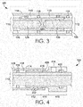
- FIG. 3 is a close-up view of the contact socket 120 and illustrates the first conductor 110 with its insulative shield 126 and also its copper core 128 extending towards the midpoint of the contact socket 120.
- FIG. 3 further illustrates the second conductor 112 with its insulative shield 126 and also its copper core 128 extending towards the midpoint of the contact socket 120.
- the contact socket 120 is configured such that a drop-off is created at the junction of the termination of the insulative shield 126 of the first conductor 110 and the contact socket 120.
- the outside diameter of the contact socket 120 is smaller than the outside diameter of the insulative shield 126 at point 310.
- the outside diameter of the contact socket 120 then gradually increases from the point 310 to point 312 such that at the point 312 the outside diameter of the contact socket 120 is slightly greater than that of the insulative shield 126 of the second conductor 112.
- the result of this is that as the seals 116 translate along the contact socket 120 from the first fitting 122 to the second fitting 124, the seals will "drop" on to the insulative shield 126 of the second conductor 112 at the point 312. The seals 116 will then continue to translate along the insulative shield 126 of the second conductor 112 as dielectric fluid continues to be distributed into the space 118.
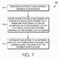
- FIG. 7 illustrates a flow diagram of an exemplary method 700 of pressure balancing a termination of an electrical cable, such as the electrical cable 105 of the cable assembly 100.
- the electrical cable is positioned within a flexible sleeve such as the flexible sleeve 114 of the cable assembly 100.
- a space such as the space 118, is thereby formed between the outer surface of the electrical cable and the inner surface of the flexible sleeve.
- a plurality of O-ring seals such as the seals 116 of the cable assembly 100, are positioned in the space by spacing the seals apart along the length of the flexible sleeve.
- dielectric fluid is distributed between each of the O-ring seals as they are being spaced along the length of the flexible sleeve.
- each adjacent pair of O-ring seals delimits and seals a chamber containing dielectric fluid, such as the chambers 119 of the assembly 100.
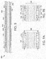
- FIG. 9A depicts a chamber 119 formed between a pair of adjacent seals 116.
- the chamber 119 is filled with dielectric fluid as evidenced by the bubbles shown in FIG. 9A .
- Any change in pressure - whether positive or negative - in the external environment is transmitted to the interior of the cable assembly 100 via, for example, the fill port 220 of the first fitting 122 and/or via the port hole 418 of the second fitting 124.
- FIG. 9A depicts a chamber 119 formed between a pair of adjacent seals 116.
- the chamber 119 is filled with dielectric fluid as evidenced by the bubbles shown in FIG. 9A .
Landscapes
- Engineering & Computer Science (AREA)
- Manufacturing & Machinery (AREA)
- Installation Of Indoor Wiring (AREA)
- Life Sciences & Earth Sciences (AREA)
- Geology (AREA)
- Mining & Mineral Resources (AREA)
- Mechanical Engineering (AREA)
- Physics & Mathematics (AREA)
- Environmental & Geological Engineering (AREA)
- Fluid Mechanics (AREA)
- General Life Sciences & Earth Sciences (AREA)
- Geochemistry & Mineralogy (AREA)
Abstract
Description
- This Summary is provided to introduce a selection of concepts in a simplified form that are further described below in the Detailed Description. This Summary is not intended to identify key features or essential features of the claimed subject matter, nor is it intended to be used as an aid in determining the scope of the claimed subject matter. The present invention is defined by the claims.
- At a high level, aspects described herein relate to a pressure-balanced cable assembly that utilizes a tubular-shaped flexible sleeve surrounding an electrical cable. A series of O-ring seals are positioned between an inner surface of the flexible sleeve and an outer surface of the electrical cable and dielectric fluid is distributed between each of the O-rings. Each adjacent pair of O-ring seals delimits and seals an individual chamber containing the dielectric fluid. The O-ring seals are independently and bi-directionally movable along the electrical cable in response to differences in pressure between the environment external to the assembly (e.g., the downhole environment) and pressures within the assembly. The use of multiple O-ring seals provides a high degree of redundancy in the case that one or more of the O-rings fail. The result is an inexpensive, flexible, low-profile pressure-balanced cable assembly that has a high degree of reliability.
- Accordingly, in one aspect of the invention, a flexible, pressure-balanced sleeve assembly for a cable termination is provided. The sleeve assembly comprises a flexible outer sleeve surrounding an electrical cable, a plurality of seals positioned between the flexible outer sleeve and the electrical cable, and a plurality of chambers defined between each of the plurality of seals. Dielectric fluid is contained within each of the plurality of chambers. The seals are independently movable along the electrical cable in response to differences between a pressure within a respective chamber and a pressure outside of the respective chamber.
- In another aspect of the invention, a flexible, pressure-balanced electrical cable assembly is provided. The cable assembly comprises an electrical cable and a flexible tubing positioned over the electrical cable. The flexible tubing defines a space between an inner surface of the flexible tubing and an outer surface of the electrical cable. A plurality of O-ring seals is positioned between the inner surface of the flexible tubing and the outer surface of the electrical cable where the plurality of O-ring seals partition the space into a plurality of individual chambers. The assembly further comprises dielectric fluid contained within each of the individual chambers. Each of the plurality of O-ring seals is independently movable along the outer surface of the electrical cable in response to differences between a pressure within the electrical cable assembly and a pressure outside of the assembly.
- In yet another aspect, a method of pressure-balancing a termination of an electrical cable is provided. The method comprises positioning the electrical cable within a flexible outer sleeve where a space is defined between an outer surface of the electrical cable and an inner surface of the flexible outer sleeve. A plurality of O-ring seals is positioned in the space. Positioning the O-ring seals comprises spacing apart each O-ring seal along a length of the flexible outer sleeve and distributing dielectric fluid between each of the plurality of O-ring seals during the positioning step. Each adjacent pair of O-ring seals delimits and seals an individual chamber containing the dielectric fluid.
- The present invention is described in detail below with reference to the attached drawing figures, wherein:
-
FIG. 1A depicts a cross-sectional view taken along a longitudinal axis of a flexible, pressure-balanced cable assembly in accordance with an aspect herein; -
FIGs. 1B-1C depict cross-sectional views taken alongline 1B-1B andline 1C-1C ofFIG. 1A in accordance with aspects herein; -
FIG. 2 depicts a cross-sectional view of a first end of a flexible, pressure-balanced cable assembly in accordance with an aspect herein; -
FIG. 3 depicts a cross-sectional view of a middle portion of a flexible, pressure-balanced cable assembly in accordance with an aspect herein; -
FIG. 4 depicts a cross-sectional view of a second end of a flexible, pressure-balanced cable assembly in accordance with an aspect herein; -
FIG. 5 depicts a side elevation view of a barb fitting used to position O-rings seals in a flexible, pressure-balanced cable assembly in accordance with an aspect herein; -
FIG. 6 depicts a cross-sectional view of a flexible, pressure-balanced cable assembly being loaded with O-ring seals in accordance with an aspect herein; -
FIG. 7 is a flow diagram of an exemplary method of pressure-balancing a termination of a cable assembly in accordance with an aspect herein; -
FIG. 8 depicts a cross-sectional view of a T-shaped fitting used to load two flexible, pressure balanced cable assemblies with O-ring seals in accordance with an aspect herein; and -
FIGs. 9A-9B depict a close-up view of a portion of a flexible, pressure-balanced cable assembly illustrating pressure-balancing characteristics of the assembly in accordance with aspects herein. - Aspects herein provide for a flexible, pressure-balanced cable assembly. The assembly comprises a flexible outer sleeve constructed from, for example, a non-electrically conductive plastic that surrounds an electrical cable. The flexible outer sleeve defines a chamber or space between an inner surface of the outer sleeve and an outer surface of the electrical cable. O-ring seals are positioned within the space effectively partitioning the space into a plurality of discrete chambers. Each of the discrete chambers is filled with a dielectric fluid. In response to a pressure differential between the inside of the cable assembly and the external environment (i.e., the environment surrounding the cable assembly), each of the O-ring seals is independently and bi-directionally movable along the electrical cable to effectuate pressure-balancing between the external and the internal environment.
- The flexible, pressure-balanced cable assembly thus described provides an economical alternative to traditional pressure-balanced assemblies constructed from multiple metal parts. The outside diameter of the flexible, pressure-balanced cable assembly, moreover, may be configured to be only slightly greater than the diameter of the electrical cable itself. The resulting low-profile of the assembly, combined with the flexible nature of the outer sleeve, makes the assembly easy to manipulate when used in, for example, a downhole oil well environment. Additionally, the use of multiple O-ring seals provides layers of redundancy which, in turn, imparts a high degree of reliability to the flexible, pressure-balanced cable assembly. By using a plastic outer sleeve instead of metal, furthermore, a closer match can be achieved between the thermal expansion rate of the plastic and that of the dielectric fluid and the insulative shield that surrounds the electrical cable. The result is that the O-ring seals do not have to travel as far to accommodate temperature changes in the downhole environment.
- As used throughout this disclosure, the term "flexible" when used in the context of the outer sleeve may be defined as the capability to bend easily without comprising the integrity of the outer sleeve. Further, as used throughout this disclosure, the term "cable" may mean a single electrical, or optical, conductor or it may mean two or more separate electrical or optical conductors joined together via, for example, a contact socket or other type of connection. The term "distal" as used throughout this disclosure means further away from a defined midpoint, while the term "proximal" means closer to the defined midpoint.
- Turning now to
FIG. 1A , a cross-sectional view taken along a longitudinal axis of a flexible, pressure-balancedcable assembly 100 is provided. Thecable assembly 100 comprises at least an electrical cable 105 (shown as afirst conductor 110 and asecond conductor 112 connected by a contact socket 120) surrounded by aflexible sleeve 114.Multiple seals 116 are spaced along the length of theflexible sleeve 114 and are disposed in an annular chamber orspace 118 created by an inner surface of the tubular-shapedflexible sleeve 114 and an outer surface of thefirst conductor 110 and thesecond conductor 112. Theannular space 118 is divided into a series ofindividual chambers 119 by theseals 116 with eachindividual chamber 119 delimited and sealed by an adjacent pair of theseals 116. Each of thechambers 119 is filled with a dielectric silicone grease or other dielectric fluid. The dielectric fluid helps to protect theelectrical cable 105 from the deleterious effects of gases and/or liquids in the downhole environment. - The
electrical cable 105 comprising thefirst conductor 110 and thesecond conductor 112 may comprise acopper conductor core 128 surrounded by, for instance, an ethylene propylene diene monomer (EPDM)insulative shield 126. Thecontact socket 120 is configured to receive the terminal end of theconductor 110 and the terminal end of theconductor 112 and to electrically and mechanically couple the twoconductors conductors - The tubular-shaped
flexible sleeve 114 is constructed from a plastic material such as, for example, perfluroalkoxy (PFA), monofluoroalkoxy (MFA), polytetrafluoroethylene (PTFE), and other similar plastics. The material selected to form theflexible sleeve 114 should generally be rated to a high temperature and have a high dielectric strength such that the material is substantially non-electrically conductive. Thesleeve 114 may have an outside diameter in the range of, for example, 13 mm to 19 mm although other diameters are contemplated as being within the scope herein. The thickness of the sleeve 114 (e.g., the difference between the outside diameter and the inside diameter of the flexible sleeve 114) may vary but is generally in the range of 2.00 mm to 3.00 mm. The length of theflexible sleeve 114 may be variable but should generally be such that it extends a predetermined distance along theconductors 110/112 starting from a midpoint of thecontact socket 120. - The
seals 116 may comprise O-ring formed from, for example, synthetic rubbers or plastics including thermoplastics. The O-rings may be circular-shaped and/or may have other shapes such as a square or a quad-type O-ring seal. The size of the O-ring is dependent on the dimensions associated with thesleeve 114 and the dimensions of theconductors 110/112. In general, the inside diameter of the O-ring should be approximately the same as the outside diameter of theconductors 110/112, and the outside diameter of the O-ring should be approximately the same as the inside diameter of theflexible sleeve 114 so that the O-ring occupies substantially all thespace 118 between the outer surface of theconductors 110/112 and the inner surface of theflexible sleeve 114 leaving no gaps. In some aspects, the outside diameter of the O-ring may be slightly greater than the inside diameter of theflexible sleeve 114 so as to form an even more occlusive seal. Alternatively, or in addition to, the inside diameter of the O-ring may be slightly less than the outside diameter of theelectrical cable 105. - The number of
seals 116 may range from a minimum of 2 up to, for example, 20, with an equal number of seals generally being positioned on either side of the midpoint of thecontact socket 120. The number ofseals 116 and the amount ofspace 118 between the outside surface of theelectrical cable 105 and the inside surface of theflexible sleeve 114 will determine the number and size of thechambers 119. The number and size of thechambers 119, in turn, will determine the volume of dielectric fluid within thecable assembly 100. - In aspects, the dimensions of the
flexible sleeve 114 and the dimensions of theseals 116 may be adjusted so as to maintain a fairly consistent volume of dielectric fluid within thecable assembly 100 in order to achieve adequate protection for theelectrical cable 105. For instance, in situations where a low profile and a high amount of flexibility of thecable assembly 100 is desirable, theflexible sleeve 114 may be selected to have an outside diameter that is only slightly greater than the diameter of theelectrical cable 105. Assuming the thickness of thesleeve 114 is constant, this reduces the amount ofspace 118 between the inner surface of theflexible sleeve 114 and the outer surface of theelectrical cable 105. To maintain a somewhat consistent volume of dielectric fluid in this situation, the length of theflexible sleeve 114 may be increased and a greater number ofseals 116 having a smaller outside diameter may be utilized to create a greater number ofchambers 119. Conversely, if the profile characteristics of thecable assembly 100 are not that important and/or if a short length of theflexible sleeve 114 is needed, theflexible sleeve 114 may be selected to have a larger outside diameter. Again assuming the thickness of theflexible sleeve 114 remains the same, there will be a greater amount ofspace 118 between the inner surface of theflexible sleeve 114 and the outer surface of theelectrical cable 105. In this situation, a fewer number ofseals 116 having a larger outside diameter may be utilized to create a fewer number ofchambers 119 having a larger volume such that the total quantity of dielectric fluid remains the same. - The
seals 116 are adapted to be bi-directionally and independently movable along the outer surface of theelectrical cable 105 and the inner surface of theflexible sleeve 114 in response to pressure differentials between the interior of thecable assembly 100 and the external environment. More specifically, the inside diameter of theseals 116 is in direct contact with the outer surface of theinsulative shield 126 and translates along the surface of theinsulative shield 126 in response to the pressure differential. Further, the outside diameter of theseals 116 is in direct contact with the inner surface of theflexible sleeve 114 and translates along inner surface of theflexible sleeve 114 in response to the pressure differential. By having the inner surface of theseals 116 in direct contact with theinsulative shield 126 and by having the outer surface of theseals 116 in direct contact with the inner surface of theflexible sleeve 114, a lower overall outside diameter of thecable assembly 100 may be achieved as opposed to pressure-balancing assemblies that rely on multiple, metal machined parts and/or shuttles to achieve pressure balancing. -
FIG. 1B depicts a cross-sectional view of theassembly 100 taken alongline 1B-1B ofFIG. 1A. FIG. 1B depicts theflexible sleeve 114 surrounding theelectrical cable 105 comprising thecopper conductor core 128 surrounded by theinsulative shield 126. The space defined by the inner surface of theflexible sleeve 114 and the outer surface of theinsulative shield 126 is occupied by the O-ring seal 116. More specifically, an inner surface of theseal 116 having aninside diameter 136 rests against the outer surface of theinsulative shield 126, and the outer surface of theseal 116 having anoutside diameter 134 rests against the inner surface of theflexible sleeve 114, where the inner surface has aninside diameter 132. In aspects, theouter diameter 134 of theseal 116 is generally equal to theinside diameter 132 of thesleeve 114.FIG. 1B further depicts the outer surface of theflexible sleeve 114 having anoutside diameter 130. -
FIG. 1C depicts a cross-sectional view of thecable assembly 100 taken alongline 1C-1C ofFIG. 1A . This section of theassembly 100 does not contain aseal 116. Instead, as shown inFIG. 1C , achamber 119 is defined between the inner surface of theflexible sleeve 114 and the outer surface of theinsulative shield 126. Thechamber 119 is filled with a dielectric fluid as shown by the bubbles in thechamber 119. - Returning to
FIG. 1A , thecable assembly 100 may optionally comprise afirst fitting 122 and asecond fitting 124 disposed at a first end and a second end of theflexible sleeve 114 respectively. Thefittings cable assembly 100 to perform its pressure-balancing function but may be useful to facilitate assembly of thecable assembly 100 and/or to mechanically couple theassembly 100 to other equipment as will be explained below. -
FIG. 2 depicts a close-up cross-sectional view of thefirst fitting 122 taken along its longitudinal axis in accordance with an aspect herein. Thefirst fitting 122 is tubular shaped and is attached to afirst end 205 of theflexible sleeve 114. Thefirst fitting 122 surrounds thefirst conductor 110, and anannular cavity 212 is formed between the inner surface of the tubular-shapedfirst fitting 122 and the outer surface of theconductor 110. Theannular cavity 212 is in communication with thespace 118 created by the inner surface of theflexible sleeve 114, and the outer surface of theconductor 110. Thefirst fitting 122 may be formed from materials comprising metals, plastics, thermoplastics, nylon or any combination thereof. - The
first fitting 122 comprises afirst portion 214, asecond portion 216, and an interveningportion 218 connecting thefirst portion 214 with thesecond portion 216. With respect to thefirst portion 214, thefirst portion 214 may comprise a threadedfill port 220 that is in communication with the environment external to thecable assembly 100 and the interior of thecable assembly 100. To put it another way, thefill port 220 provides a communication path from the external environment (e.g., the downhole environment) through thefill port 220, into theannular cavity 212 and up to thefirst seal 116 located in thespace 118 between the outer surface of theconductor 110 and the inner surface of theflexible sleeve 114. By having anopen fill port 220, any changes in pressure - whether positive or negative - are effectively communicated to the interior of thecable assembly 100 where the change in pressure can be balanced via movement of theseals 116 along theflexible sleeve 114/electrical cable 105. Thefirst seal 116 shown inFIG. 2 prevents any harmful liquids or fluids from the downhole environment from coming into contact with the connection between thefirst conductor 110 and thesecond conductor 112 at thecontact socket 120. A grease gun may be connected to thefill port 220 and dielectric fluid or grease can be distributed into thespace 118 via thefill port 220. This process will be explained in greater depth below with respect toFIGs. 5-7 . - The
first portion 214 may further comprise aseal 222 located distal to the fill port 220 (i.e., further away from the midpoint of the contact socket 120). Theseal 222 may be used to prevent any dielectric fluid inserted via thefill port 220 from escaping theassembly 100. Optionally, thefirst portion 214 may also be adapted to be attached to other devices used in downhole environments such as, for example, an electric submersible pump (ESP). - The
second portion 216 of thefirst fitting 122 comprises a series ofbarbs 224 that are adapted to mechanically couple thefirst fitting 122 to thefirst end 205 of theflexible sleeve 114 by engaging the inner surface of theflexible sleeve 114. The interveningportion 218 has a smooth outer surface. When assembling thecable assembly 100, theseals 116 may first be loaded onto the interveningportion 218 prior to being positioned along the length of theflexible sleeve 114. To put it another way, the interveningportion 218 may act to retain theseals 116 prior to assembling thecable assembly 100. Thus, the length of the interveningportion 218 may be configurable based on the number ofseals 116 to be positioned along the length of the flexible sleeve 114 - the greater number ofseals 116, the longer the interveningportion 218, and the lesser number ofseals 116, the shorter the length of the interveningportion 218. -
FIG. 4 depicts a close-up cross-sectional view of thesecond fitting 124 taken along its longitudinal axis. Thesecond fitting 124 is tubular shaped and is attached to asecond end 405 of theflexible sleeve 114. Thesecond fitting 124 surrounds thesecond conductor 112, and anannular cavity 416 is formed between the inner surface of the tubular-shapedsecond fitting 124 and the outer surface of theconductor 112. Theannular cavity 416 is in communication with thespace 118 created by the inner surface of theflexible sleeve 114 and the outer surface of theconductor 112. Thesecond fitting 124 may be formed from materials comprising metals, plastics, thermoplastic, nylon or any combination thereof. - The
second fitting 124 comprises afirst portion 410, asecond portion 412, and an interveningportion 414 that connects thefirst portion 410 to thesecond portion 412. Thefirst portion 410 comprises anopen port hole 418 that is in communication with the external environment and theannular cavity 416. Similar to thefill port 220 of thefirst fitting 122, theport hole 418 acts to convey pressure differences - whether positive or negative - between the external environment and the interior of thecable assembly 100, where the pressure differences are balanced via movement of theseals 116 along theflexible sleeve 114/electrical cable 105. Thefirst seal 116 shown inFIG. 4 helps to prevent harmful liquids or fluids from the downhole environment from coming into contact with the connection between thefirst conductor 110 and thesecond conductor 112 at thecontact socket 120. Thefirst portion 410 may further comprise aseal 420 located distal (i.e., further away from the midpoint of the contact socket 120) to theport hole 418. Theseal 420 acts to prevent loss of dielectric fluid from theassembly 100. Optionally, thefirst portion 410 may also be adapted to be attached to other devices used in downhole environments. - The
second portion 412 of thesecond fitting 124 comprises a series ofbarbs 422 that are adapted to mechanically engage with the inner surface of thesecond end 405 of theflexible sleeve 114. In an exemplary aspect, the length of the interveningportion 414 of thesecond fitting 124 may be less than that of the interveningportion 218 of thefirst fitting 122. This is generally because, in an exemplary aspect, thesecond fitting 124 may not be used to load/retain theseals 116 when assembling thecable assembly 100. - In an exemplary aspect, the
cable assembly 100 may optionally comprise a coil spring located at each end of thecable assembly 100 to achieve a slightly higher pressure bias within theassembly 100 as compared to the external environment. By having a slightly higher pressure bias within theassembly 100, a failure of one or more of theseals 116 will cause dielectric fluid to exit theassembly 100 instead of fluids from the downhole environment entering theassembly 100 and potentially causing an electrical short. - In yet another exemplary aspect, the
cable assembly 100 may be configured such that theflexible sleeve 114 is positioned over just theelectrical cable 110 and a bulkhead pressure block connector is used to connect theelectrical cable 112 to theelectrical cable 110. This same configuration holds true if theflexible sleeve 114 is positioned over just theelectrical cable 112. Any and all such aspects, and any variation thereof, are contemplated as being within the scope herein. -
FIGs. 5 and 6 illustrate aspects of how theseals 116 are loaded onto thecable assembly 100 in one exemplary aspect. The loading process may occur off-site (e.g., at a manufacturing site) or on-site (e.g., at the downhole oil well environment).FIG. 5 depicts a side elevation view of thefirst fitting 122 unaffixed to theflexible sleeve 114 of thecable assembly 100.FIG. 5 illustrate a number ofseals 116 loaded on to the interveningportion 218. This may occur by loading theseals 116 onto aterminal end 510 of thesecond portion 216, sliding them over thebarbs 224, and sliding them along the interveningportion 218. The loading of theseals 116 may occur via a manual or an automated process. -
FIG. 6 depicts a cross-sectional view of thecable assembly 100 taken along its longitudinal axis after theseals 116 have been loaded on to thefirst fitting 122 but prior to theseals 116 being positioned along the length of theflexible sleeve 114. In this exemplary view, thefirst conductor 110 is coupled to thesecond conductor 112 via thecontact socket 120 and theflexible sleeve 114 is positioned over theconductors 110/112 and thecontact socket 120 prior to theseals 116 being positioned along the length of theflexible sleeve 114. One exemplary process for positioning theseals 116 along the length of theflexible sleeve 114 comprises unloading afirst seal 610 from thesecond portion 216 of thefirst fitting 122 by, for example, pulling thefirst seal 610 over thebarbs 224 and positioning theseal 610 at theterminal end 510 of thesecond portion 216, and then coupling thefirst fitting 122 to thefirst end 205 of theflexible sleeve 114 via thebarbs 224. Once thefirst fitting 122 is engaged with theflexible sleeve 114, a grease gun can then be fitted into thefill port 220 and a redefined quantity of dielectric fluid may be inserted into theannular cavity 212. Because of the occlusive seal formed by thefirst seal 610, distribution of dielectric fluid into theannular cavity 212 acts to move the first seal 610 a predetermined distance in thespace 118 created by the inner surface of theflexible sleeve 114 and the outer surface of theelectrical cable 105. - Next, the
first fitting 122 may be disengaged from theflexible sleeve 114, and asecond seal 116 may be moved from the interveningportion 218, over thebarbs 224, and on to theterminal end 510. Thefirst fitting 122 is then re-coupled with theflexible sleeve 114 and dielectric grease is again inserted via thefill port 220 until thesecond seal 116 moves a predetermined distance in thespace 118 created by the inner surface of theflexible sleeve 114 and the outer surface of theelectrical cable 105. The process is repeated until all of theseals 116 have been positioned along the length of thefirst conductor 110 and thesecond conductor 112 and dielectric fluid fills eachchamber 119 created by each adjacent pair ofseals 116. - In another exemplary loading process, the
first conductor 110 may not yet be coupled to thesecond conductor 112 via thecontact socket 120, and theflexible sleeve 114 may be positioned just over thefirst conductor 110. In this arrangement, theseals 116 may be positioned along a substantial portion of the length of thefirst conductor 110 using the process set forth above. Thecontact socket 120 may then be used to couple thefirst conductor 110 to thesecond conductor 112. Next, theflexible sleeve 114 may then be slid over thesecond conductor 112 until the midpoint of theflexible sleeve 114 is generally positioned over the midpoint of thecontact socket 120 and an equal number ofseals 116 are generally positioned on either side of the midpoint of thecontact socket 120. - Another exemplary arrangement used to load the
seals 116 onto the cable assembly is shown inFIG. 8. FIG. 8 depicts across-sectional view 800 of a T-shapedfitting 810 taken along its longitudinal axis. The two arms of the tubular-shapedfitting 810 are coupled to a first end of a firstflexible sleeve 812 and a first end of a second flexible sleeve 814 by barbs, where both the first andsecond sleeves 812 and 814 surround anelectrical cable 816. Aspace 820 is created between the inner surface of the fitting 810 and the outer surface of theelectrical cable 816; thespace 820 is in communication with thespace 118 created between the inner surface of thesleeves 812 and 814 and the outer surface of theelectrical cable 816. Theseals 116 may be loaded onto portions of the arms of the fitting 810. Theseals 116 may then be simultaneously offloaded from the T-shapedfitting 810 into thespace 118 pursuant to dielectric fluid being injected via thefill port 818. The process by which this occurs is similar to that set forth above with respect to, for example,FIG. 6 . Any and all such aspects, and any variation thereof, are contemplated as being within the scope herein. - Returning to, for example,
FIG. 6 , thecontact socket 120 may be configured as is illustrated inFIG. 3 to facilitate a smooth translation of theseals 116 at the connection between thefirst conductor 110 and thesecond conductor 112 when positioning theseals 116 along the length of theflexible sleeve 114.FIG. 3 is a close-up view of thecontact socket 120 and illustrates thefirst conductor 110 with itsinsulative shield 126 and also itscopper core 128 extending towards the midpoint of thecontact socket 120. Likewise,FIG. 3 further illustrates thesecond conductor 112 with itsinsulative shield 126 and also itscopper core 128 extending towards the midpoint of thecontact socket 120. As shown atreference numeral 130, thecontact socket 120 is configured such that a drop-off is created at the junction of the termination of theinsulative shield 126 of thefirst conductor 110 and thecontact socket 120. In other words, the outside diameter of thecontact socket 120 is smaller than the outside diameter of theinsulative shield 126 atpoint 310. Thus, as theseals 116 are moving from the direction of thefirst fitting 122 towards thesecond fitting 124, theseals 116 translate from theinsulative shield 126 of thefirst conductor 110 onto thecontact socket 120 atpoint 130. - The outside diameter of the
contact socket 120 then gradually increases from thepoint 310 to point 312 such that at thepoint 312 the outside diameter of thecontact socket 120 is slightly greater than that of theinsulative shield 126 of thesecond conductor 112. The result of this is that as theseals 116 translate along thecontact socket 120 from thefirst fitting 122 to thesecond fitting 124, the seals will "drop" on to theinsulative shield 126 of thesecond conductor 112 at thepoint 312. Theseals 116 will then continue to translate along theinsulative shield 126 of thesecond conductor 112 as dielectric fluid continues to be distributed into thespace 118. -
FIG. 7 illustrates a flow diagram of anexemplary method 700 of pressure balancing a termination of an electrical cable, such as theelectrical cable 105 of thecable assembly 100. At astep 710, the electrical cable is positioned within a flexible sleeve such as theflexible sleeve 114 of thecable assembly 100. A space, such as thespace 118, is thereby formed between the outer surface of the electrical cable and the inner surface of the flexible sleeve. At astep 712, a plurality of O-ring seals, such as theseals 116 of thecable assembly 100, are positioned in the space by spacing the seals apart along the length of the flexible sleeve. At astep 714, dielectric fluid is distributed between each of the O-ring seals as they are being spaced along the length of the flexible sleeve. Thus, each adjacent pair of O-ring seals delimits and seals a chamber containing dielectric fluid, such as thechambers 119 of theassembly 100. - In operation, as shown in
FIGS. 9A and 9B , theseals 116 translate along the inner surface of theflexible sleeve 114 and the outer surface of theelectrical cable 105. More particularly,FIG. 9A depicts achamber 119 formed between a pair ofadjacent seals 116. Thechamber 119 is filled with dielectric fluid as evidenced by the bubbles shown inFIG. 9A . Any change in pressure - whether positive or negative - in the external environment is transmitted to the interior of thecable assembly 100 via, for example, thefill port 220 of thefirst fitting 122 and/or via theport hole 418 of thesecond fitting 124. As shown inFIG. 9B , an increase in pressure in the external environment will cause air pockets or compressible elements within the dielectric fluid to contract in volume (as shown be the decrease in bubble size inFIG. 9B ), allowing theseals 116 to move closer to one another as shown by the arrows. Theseals 116 may return to their original position shown inFIG. 9A once the external pressure subsides. This is known as pressure-balancing. - Many different arrangements of the various components depicted, as well as components not shown, are possible without departing from the scope of the claims below. Aspects of our technology have been described with the intent to be illustrative rather than restrictive. Alternative aspects will become apparent to readers of this disclosure after and because of reading it. Alternative means of implementing the aforementioned can be completed without departing from the scope of the claims below. Certain features and subcombinations are of utility and may be employed without reference to other features and subcombinations and are contemplated within the scope of the claims.
Claims (15)
- A flexible, pressure-balanced sleeve assembly for a cable termination, the sleeve assembly comprising:a flexible outer sleeve (114) surrounding an electrical cable (105);a plurality of seals (116) positioned between the flexible outer sleeve (114) and the electrical cable (105);a plurality of chambers (119) defined between each of the plurality of seals (116); and dielectric fluid contained within the each of the plurality of chambers (119), wherein the each of the plurality of seals (116) is independently movable along the electrical cable (105) in response to differences between a pressure within a respective chamber (119) and a pressure outside of the respective chamber (119).
- The flexible, pressure-balanced sleeve assembly of claim 1, wherein the flexible outer sleeve (114) comprises a non-electrically conductive plastic and/or wherein the electrical cable (105) comprises an inner conductive core (128) and an insulative layer (126) positioned over the inner conductive core (128).
- The flexible, pressure-balanced sleeve assembly of claim 1, wherein the plurality of seals (116) comprises 0-ring seals and/or wherein the each of the plurality of seals (116) is spaced apart from one another.
- The flexible, pressure-balanced sleeve assembly of claim 1, further comprising:a first fitting (122) surrounding the electrical cable (105) and attached to a first end of the flexible outer sleeve (114); anda second fitting (124) surrounding the electrical cable (105) and attached to a second end of the flexible outer sleeve (114).
- The flexible, pressure-balanced sleeve assembly of claim 4, wherein the first fitting (122) comprises a fill port (220) for distributing the dielectric fluid contained within the each of the plurality of chambers (119), preferably wherein the fill port (220) is in communication with an environment external to the flexible, pressure-balanced sleeve assembly.
- The flexible, pressure-balanced sleeve assembly of claim 5, wherein the second fitting (124) comprises a port hole (418) that is in communication with the environment external to the flexible, pressure-balanced sleeve assembly.
- A flexible, pressure-balanced electrical cable assembly (100) comprising:an electrical cable (105);a flexible tubing (114) positioned over the electrical cable (105) and defining a space (118) between an inner surface of the flexible tubing (114) and an outer surface of the electrical cable (105);a plurality of 0-ring seals (116) positioned between the inner surface of the flexible tubing (114) and the outer surface of the electrical cable (105), the plurality of 0-ring seals (116) partitioning the space (118) into a plurality of individual chambers (119); anddielectric fluid contained within each of the individual chambers (119), wherein each of the plurality of 0-ring seals (116) is independently movable along the outer surface of the electrical cable (105) in response to differences between a pressure within the flexible, pressure-balanced electrical cable assembly (100) and a pressure outside of the assembly (100).
- The flexible, pressure-balanced electrical cable assembly (100) of claim 7, wherein the electrical cable (105) comprises an inner conductive core (128) and an insulative layer (126) positioned over the inner conductive core (128) and/or wherein the electrical cable (105) comprises at least a first conductor (110) and a second conductor (112) joined together via a contact socket (120).
- The flexible, pressure-balanced electrical cable assembly (100) of claim 8, wherein the flexible tubing (114) comprises a non-electrically conductive plastic.
- The flexible, pressure-balanced electrical cable assembly (100) of claim 9, wherein the plurality of 0-ring seals (116) is positioned between the inner surface of the flexible tubing (114) and an outer surface of the insulative layer (126) of the electrical cable (105).
- The flexible, pressure-balanced electrical cable assembly (100) of claim 7, wherein each adjacent pair of 0-ring seals (116) delimits and seals a respective individual chamber (119).
- The flexible, pressure-balanced electrical cable assembly (100) of claim 8, wherein a first portion of the plurality of 0-ring seals (116) is positioned between the inner surface of the flexible tubing (114) and the outer surface of the first conductor (110), and wherein a second portion of the plurality of 0-ring seals (116) is positioned between the inner surface of the flexible tubing (114) and the outer surface of the second conductor (112).
- The flexible, pressure-balanced electrical cable assembly (100) of claim 7, further comprising a first fitting (122) surrounding the electrical cable (105) and attached to a first end of the flexible tubing (114), the first fitting (122) comprising at least a fill port (220) useable for distributing the dielectric fluid contained with the each of the individual chambers (119), the fill port (220) in communication with an external environment, the assembly preferably further comprising a second fitting (124) surrounding the electrical cable (105) and attached to a second end of the flexible tubing (114), the second fitting (124) comprising at least a port hole (418) in communication with the external environment.
- A method of pressure-balancing a termination of an electrical cable (105), the method comprising:positioning the electrical cable (105) within a flexible outer sleeve (114), wherein a space (118) is defined between an outer surface of the electrical cable (105) and an inner surface of the flexible outer sleeve (114);positioning a plurality of 0-ring seals (116) in the space (118), wherein positioning the plurality of 0-ring seals (116) comprises:spacing apart each 0-ring seal (116) of the plurality of 0-ring seals (116) along a length of the flexible outer sleeve (114); anddistributing dielectric fluid between the each of the plurality of 0- ring seals (116), wherein each adjacent pair of 0-ring seals (116) delimits and seals an individual chamber (119) containing the dielectric fluid.
- The method of claim 14, wherein the electrical cable (105) comprises at least a first conductor (110) and a second conductor (112) joined together via a contact socket (120).
Applications Claiming Priority (1)
| Application Number | Priority Date | Filing Date | Title |
|---|---|---|---|
| US14/601,589 US9793029B2 (en) | 2015-01-21 | 2015-01-21 | Flexible, pressure-balanced cable assembly |
Publications (1)
| Publication Number | Publication Date |
|---|---|
| EP3054545A1 true EP3054545A1 (en) | 2016-08-10 |
Family
ID=55237506
Family Applications (1)
| Application Number | Title | Priority Date | Filing Date |
|---|---|---|---|
| EP16152201.6A Withdrawn EP3054545A1 (en) | 2015-01-21 | 2016-01-21 | Flexible, pressure-balanced cable assembly |
Country Status (2)
| Country | Link |
|---|---|
| US (1) | US9793029B2 (en) |
| EP (1) | EP3054545A1 (en) |
Cited By (1)
| Publication number | Priority date | Publication date | Assignee | Title |
|---|---|---|---|---|
| CN111817209A (en) * | 2020-06-03 | 2020-10-23 | 宁波新思创机电科技股份有限公司 | Cable Sleeve Assembly Equipment |
Families Citing this family (7)
| Publication number | Priority date | Publication date | Assignee | Title |
|---|---|---|---|---|
| US9853394B2 (en) * | 2014-05-02 | 2017-12-26 | Itt Manufacturing Enterprises, Llc | Pressure-blocking feedthru with pressure-balanced cable terminations |
| US9843113B1 (en) | 2017-04-06 | 2017-12-12 | Itt Manufacturing Enterprises Llc | Crimpless electrical connectors |
| US10276969B2 (en) | 2017-04-20 | 2019-04-30 | Itt Manufacturing Enterprises Llc | Connector with sealing boot and moveable shuttle |
| US9941622B1 (en) | 2017-04-20 | 2018-04-10 | Itt Manufacturing Enterprises Llc | Connector with sealing boot and moveable shuttle |
| US12009118B2 (en) * | 2021-09-15 | 2024-06-11 | Wesco Distribution, Inc. | Apparatus for applying a sleeve to a cable and method of insertion into a conduit |
| CN117810898A (en) * | 2023-12-29 | 2024-04-02 | 宁波东方电缆股份有限公司 | Sealing structure, cable and cable equipment |
| CN121670955B (en) * | 2026-02-10 | 2026-05-05 | 四川胜桦电缆有限公司 | A polyolefin insulated flexible cable extruder |
Citations (4)
| Publication number | Priority date | Publication date | Assignee | Title |
|---|---|---|---|---|
| US20030148638A1 (en) * | 2002-02-06 | 2003-08-07 | Mchugh Marcus D. | Technique for providing power to a completion used in a subterranean environment |
| WO2009097609A1 (en) * | 2008-02-01 | 2009-08-06 | Quick Connectors, Inc. | Segmented decompression resistant cable splice and method of installation |
| US20120097444A1 (en) * | 2010-10-26 | 2012-04-26 | M.C. Miller Co. | Method of splicing electrical cables |
| US20140097001A1 (en) * | 2012-10-04 | 2014-04-10 | Itt Manufacturing Enterprises Llc | Pressure balanced connector termination |
Family Cites Families (69)
| Publication number | Priority date | Publication date | Assignee | Title |
|---|---|---|---|---|
| US3641479A (en) | 1969-06-16 | 1972-02-08 | Obrien D G Inc | Underwater disconnectible connector |
| US3652777A (en) | 1970-03-16 | 1972-03-28 | Electrical Constructors And As | Automatic stop joint for pipe-type cable |
| US3729699A (en) | 1971-06-29 | 1973-04-24 | Southwest Res Inst | Underwater wet electrical connector |
| FR2350496A1 (en) | 1976-05-03 | 1977-12-02 | Matra Engins | AUTOMATIC CONNECTOR AND APPLICATION OF THE DIT CONNECTOR TO SUBMARINE CONNECTION MODULES |
| US4105279A (en) | 1976-12-16 | 1978-08-08 | Schlumberger Technology Corporation | Removable downhole measuring instruments with electrical connection to surface |
| US4142770A (en) | 1977-12-27 | 1979-03-06 | Exxon Production Research Company | Subsea electrical connector |
| US4174875A (en) | 1978-05-30 | 1979-11-20 | The United States Of America As Represented By The Secretary Of The Navy | Coaxial wet connector with spring operated piston |
| FR2484717A1 (en) | 1980-02-22 | 1981-12-18 | Inst Francais Du Petrole | CONNECTOR POSSIBLE IN A FLUID ENVIRONMENT |
| US4488765A (en) | 1980-06-18 | 1984-12-18 | The United States Of America As Represented By The Secretary Of The Navy | Dead-faced electrical connector with electromagnetic vulnerability protection |
| US4561679A (en) | 1982-07-26 | 1985-12-31 | Exxon Production Research Co. | Seal pressure reduction system |
| US4500151A (en) | 1982-11-19 | 1985-02-19 | Shell Oil Company | Marine electrical plug |
| US4797117A (en) | 1982-12-23 | 1989-01-10 | Shell Oil Company | Marine electrical plug |
| US4500156A (en) | 1983-03-02 | 1985-02-19 | Schlumberger Technology Corporation | Electrical connector |
| DE3308178C1 (en) | 1983-03-08 | 1984-04-05 | RAWE Datentechnik GmbH, 8999 Weiler | Line clamp device |
| US4767349A (en) | 1983-12-27 | 1988-08-30 | Schlumberger Technology Corporation | Wet electrical connector |
| US4589717A (en) | 1983-12-27 | 1986-05-20 | Schlumberger Technology Corporation | Repeatedly operable electrical wet connector |
| US4780574A (en) | 1987-04-16 | 1988-10-25 | Hubbell Incorporated | Lead sheathed power cable |
| FR2618613B1 (en) | 1987-07-23 | 1989-11-10 | Total Petroles | UNDERWATERABLE ELECTRICAL CONNECTOR |
| US4880390A (en) | 1987-08-06 | 1989-11-14 | Hughes Aircraft Company | Pressure compensated intermodule towed array connector |
| US4948377A (en) | 1988-02-18 | 1990-08-14 | Cairns James L | Submersible electrical connector |
| GB2264201B (en) | 1992-02-13 | 1996-06-05 | Swift 943 Ltd | Electrical connector |
| DE637675T1 (en) | 1993-08-04 | 1997-06-26 | Cooper Ind Inc | Electrical connection. |
| US5645442A (en) | 1995-01-19 | 1997-07-08 | Ocean Design, Inc. | Sealed, Fluid-filled electrical connector |
| US5760334A (en) | 1996-07-24 | 1998-06-02 | Alcatel Kabel Ag & Co. | Metallic sheath for an electric cable and method of making the same |
| US5907128A (en) * | 1997-02-13 | 1999-05-25 | Utilx Corporation | Cable connector with fluid injection port |
| US20020046865A1 (en) * | 1997-02-13 | 2002-04-25 | Glen J. Bertini | Cable fluid injection sleeve |
| US5899765A (en) | 1997-04-04 | 1999-05-04 | Lockheed Martin Services, Inc. | Dual bladder connector |
| GB2330702A (en) | 1997-09-09 | 1999-04-28 | Hydro Bond Engineering Limited | Electrical and/or optical connector |
| US6626049B1 (en) | 1999-04-01 | 2003-09-30 | Panametrics, Inc. | Clamp-on steam/gas flow meter |
| US6559383B1 (en) * | 1999-07-21 | 2003-05-06 | Input/Output, Inc. | Connector housing |
| DE10025140C1 (en) | 2000-05-20 | 2001-10-31 | Gisma Steckverbinder Gmbh | Pressure-equalizing jack-plug connector has each sealed contact sleeve provided with sliding piston and pressure-equalizing valves |
| DE10032616A1 (en) | 2000-07-08 | 2002-01-24 | Mhm Harzbecher Medizintechnik | System element for transducer connection in pressure-monitoring sets for extracorporeal circuits, e.g. in open-heart surgery, has a measuring chamber with a membrane which fits in a special channel in the housing |
| US6326550B1 (en) * | 2000-11-13 | 2001-12-04 | General Dynamics Advanced Technology Systems, Inc. | Cable seal |
| EP1251598A1 (en) | 2001-04-04 | 2002-10-23 | Diamould Ltd. | Wet mateable connector |
| GB2379806A (en) | 2001-06-20 | 2003-03-19 | Philip Head | Cable and connection for down hole environment |
| US20040262025A1 (en) * | 2001-09-21 | 2004-12-30 | Konrad Brandt | Multi-part insulating cover |
| EP1451832A1 (en) | 2001-10-12 | 2004-09-01 | Southwire Company | Superconducting cable termination |
| US7358435B2 (en) | 2001-12-17 | 2008-04-15 | Prysmian Cavi E Sistemi Energia S.R.L. | Electric power transport system comprising a cold dielectric superconducting cable |
| US6796821B2 (en) | 2002-06-06 | 2004-09-28 | Ocean Design, Inc. | Field installable cable termination assembly |
| NO319369B1 (en) | 2002-07-11 | 2005-07-25 | Nexans | The subsea connector |
| GB2402558A (en) | 2003-06-05 | 2004-12-08 | Abb Vetco Gray Ltd | Electrical penetrator connector |
| US6780037B1 (en) | 2003-10-07 | 2004-08-24 | Baker Hughes Incorporated | Debris seal for electrical connectors of pump motors |
| AU2004282358B2 (en) | 2003-10-09 | 2007-11-29 | Shell Internationale Research Maatschappij B.V. | Method for interconnecting electrical conduits in a borehole |
| SE0400100D0 (en) | 2004-01-16 | 2004-01-16 | Ericsson Telefon Ab L M | sealing device |
| EP1782436B1 (en) | 2004-03-01 | 2017-05-31 | Novinium, Inc. | Method for treating electrical cable at sustained elevated pressure |
| NO20044873D0 (en) | 2004-11-09 | 2004-11-09 | Framo Eng As | EL power / signal transmission system |
| TWM278133U (en) | 2005-04-14 | 2005-10-11 | John Peng | Shielded waterproof connector |
| US7291028B2 (en) | 2005-07-05 | 2007-11-06 | Hall David R | Actuated electric connection |
| US7528513B2 (en) | 2005-08-17 | 2009-05-05 | Illinois Tool Works Inc. | Shaft current control brush assembly with drainage |
| US7538274B2 (en) | 2006-01-23 | 2009-05-26 | Novinium, Inc. | Swagable high-pressure cable connectors having improved sealing means |
| NO325860B1 (en) | 2006-06-30 | 2008-08-04 | Vetco Gray Scandinavia As | Connector arrangement with a penetrator in a submersible electrical assembly |
| CA2669292C (en) | 2006-11-09 | 2016-02-09 | Expro Meters, Inc. | Apparatus and method for measuring a fluid flow parameter within an internal passage of an elongated body |
| US7520768B2 (en) | 2007-03-15 | 2009-04-21 | Schlumberger Technology Corporation | Connector assembly for use with an electrical submersible component in a deepwater environment |
| US7973241B2 (en) | 2007-09-10 | 2011-07-05 | 3M Innovative Properties Company | Pressure restraining enclosure for cables |
| US7737361B2 (en) | 2008-02-25 | 2010-06-15 | Corning Cable Systems Llc | Sealant gel for a telecommunication enclosure |
| US7695301B2 (en) | 2008-08-07 | 2010-04-13 | Teledyne Odi, Inc. | Submersible connector with secondary sealing device |
| US7828573B2 (en) | 2008-10-28 | 2010-11-09 | S&N Pump Company | Subsea electrical connector and method |
| US8087949B2 (en) | 2009-05-26 | 2012-01-03 | John Mezzalingua Associates, Inc. | Connector with a threaded actuator and a sealing component entirely within a nut component |
| US7959454B2 (en) | 2009-07-23 | 2011-06-14 | Teledyne Odi, Inc. | Wet mate connector |
| EP2499706B1 (en) | 2009-11-11 | 2016-08-24 | Teledyne Instruments, Inc. | Keyless harsh environment connector |
| US8025506B2 (en) | 2010-01-20 | 2011-09-27 | Teledyne Odi, Inc. | Harsh environment rotary joint electrical connector |
| GB201007841D0 (en) | 2010-05-11 | 2010-06-23 | Rms Ltd | Underwater electrical connector |
| US8899841B2 (en) * | 2012-01-18 | 2014-12-02 | Teledyne Instruments, Inc. | Pressure-balanced subsea junction box and cable termination apparatus and method |
| US8859899B2 (en) | 2012-02-10 | 2014-10-14 | Itt Manufacturing Enterprises, Llc | Electrical connector for cables |
| US20130312996A1 (en) | 2012-05-24 | 2013-11-28 | Schlumberger Technology Corporation | Pressure balanced coiled tubing cable and connection |
| US8816196B2 (en) * | 2012-10-04 | 2014-08-26 | Itt Manufacturing Enterprises Llc | Pressure balanced connector termination |
| GB2506635B (en) | 2012-10-04 | 2016-06-01 | Siemens Ag | Downhole cable termination systems |
| CA2826753C (en) | 2013-10-15 | 2016-05-03 | Geo Pressure Systems Inc. | Cable connection system |
| US9853394B2 (en) | 2014-05-02 | 2017-12-26 | Itt Manufacturing Enterprises, Llc | Pressure-blocking feedthru with pressure-balanced cable terminations |
-
2015
- 2015-01-21 US US14/601,589 patent/US9793029B2/en active Active
-
2016
- 2016-01-21 EP EP16152201.6A patent/EP3054545A1/en not_active Withdrawn
Patent Citations (4)
| Publication number | Priority date | Publication date | Assignee | Title |
|---|---|---|---|---|
| US20030148638A1 (en) * | 2002-02-06 | 2003-08-07 | Mchugh Marcus D. | Technique for providing power to a completion used in a subterranean environment |
| WO2009097609A1 (en) * | 2008-02-01 | 2009-08-06 | Quick Connectors, Inc. | Segmented decompression resistant cable splice and method of installation |
| US20120097444A1 (en) * | 2010-10-26 | 2012-04-26 | M.C. Miller Co. | Method of splicing electrical cables |
| US20140097001A1 (en) * | 2012-10-04 | 2014-04-10 | Itt Manufacturing Enterprises Llc | Pressure balanced connector termination |
Cited By (1)
| Publication number | Priority date | Publication date | Assignee | Title |
|---|---|---|---|---|
| CN111817209A (en) * | 2020-06-03 | 2020-10-23 | 宁波新思创机电科技股份有限公司 | Cable Sleeve Assembly Equipment |
Also Published As
| Publication number | Publication date |
|---|---|
| US20160211052A1 (en) | 2016-07-21 |
| US9793029B2 (en) | 2017-10-17 |
Similar Documents
| Publication | Publication Date | Title |
|---|---|---|
| US9793029B2 (en) | Flexible, pressure-balanced cable assembly | |
| US9270051B1 (en) | Wet mate connector | |
| CA2886654C (en) | Pressure balanced connector termination | |
| US9853394B2 (en) | Pressure-blocking feedthru with pressure-balanced cable terminations | |
| US10044134B2 (en) | Wet mate connector | |
| US8382508B1 (en) | High voltage mechanical splice connector | |
| EP3438408B1 (en) | Connector assembly | |
| MX2011007047A (en) | Pothead connectors for submersible motor head and methods of assembly thereof. | |
| NO20130181A1 (en) | Pressure-lowering dielectric seal for pothead interface | |
| WO2007023250A1 (en) | High voltage wet mateable electrical connector | |
| BR102012020218A2 (en) | ELECTRIC MOTOR CONNECTION WITH ISOLATED PRESSURE COMPENSATION AND RELATED METHODS | |
| US20170222355A1 (en) | Method of dry-mating a first connector part and a second connector part and connector assembly | |
| EP3152802B1 (en) | Connector unit comprising a connector part and a mating member and method for conditioning a section of the mating member | |
| CA2938868C (en) | Retention of electrical spring contacts for wet connection of down-hole tool components | |
| US20130140082A1 (en) | Wire connector assembly including splice elements for fluid environments and method of making same | |
| US20240388035A1 (en) | Single conductor sealed connector for high pressure gas pressure applications | |
| EP2763242A1 (en) | Wire connector assembly including splice elements for fluid environments and method of making same | |
| JP5409264B2 (en) | Wire connection device and method for manufacturing the same | |
| BR102024009992A2 (en) | SINGLE-LEAD SEALED CONNECTOR FOR HIGH PRESSURE GAS APPLICATIONS | |
| CA2927097C (en) | Pressure balanced connector termination |
Legal Events
| Date | Code | Title | Description |
|---|---|---|---|
| PUAI | Public reference made under article 153(3) epc to a published international application that has entered the european phase |
Free format text: ORIGINAL CODE: 0009012 |
|
| AK | Designated contracting states |
Kind code of ref document: A1 Designated state(s): AL AT BE BG CH CY CZ DE DK EE ES FI FR GB GR HR HU IE IS IT LI LT LU LV MC MK MT NL NO PL PT RO RS SE SI SK SM TR |
|
| AX | Request for extension of the european patent |
Extension state: BA ME |
|
| 17P | Request for examination filed |
Effective date: 20170210 |
|
| RBV | Designated contracting states (corrected) |
Designated state(s): AL AT BE BG CH CY CZ DE DK EE ES FI FR GB GR HR HU IE IS IT LI LT LU LV MC MK MT NL NO PL PT RO RS SE SI SK SM TR |
|
| 17Q | First examination report despatched |
Effective date: 20180810 |
|
| RIC1 | Information provided on ipc code assigned before grant |
Ipc: H02G 1/14 20060101ALI20191212BHEP Ipc: H02G 15/24 20060101ALN20191212BHEP Ipc: H02G 15/04 20060101ALI20191212BHEP Ipc: H02G 15/18 20060101AFI20191212BHEP Ipc: H02G 1/08 20060101ALN20191212BHEP Ipc: E21B 17/02 20060101ALI20191212BHEP |
|
| GRAP | Despatch of communication of intention to grant a patent |
Free format text: ORIGINAL CODE: EPIDOSNIGR1 |
|
| INTG | Intention to grant announced |
Effective date: 20200120 |
|
| STAA | Information on the status of an ep patent application or granted ep patent |
Free format text: STATUS: THE APPLICATION IS DEEMED TO BE WITHDRAWN |
|
| 18D | Application deemed to be withdrawn |
Effective date: 20200603 |