EP3054539B1 - Module latch actuator - Google Patents
Module latch actuator Download PDFInfo
- Publication number
- EP3054539B1 EP3054539B1 EP16153472.2A EP16153472A EP3054539B1 EP 3054539 B1 EP3054539 B1 EP 3054539B1 EP 16153472 A EP16153472 A EP 16153472A EP 3054539 B1 EP3054539 B1 EP 3054539B1
- Authority
- EP
- European Patent Office
- Prior art keywords
- actuator
- housing
- module
- latch
- connector
- Prior art date
- Legal status (The legal status is an assumption and is not a legal conclusion. Google has not performed a legal analysis and makes no representation as to the accuracy of the status listed.)
- Active
Links
Images




Classifications
-
- H—ELECTRICITY
- H01—ELECTRIC ELEMENTS
- H01R—ELECTRICALLY-CONDUCTIVE CONNECTIONS; STRUCTURAL ASSOCIATIONS OF A PLURALITY OF MUTUALLY-INSULATED ELECTRICAL CONNECTING ELEMENTS; COUPLING DEVICES; CURRENT COLLECTORS
- H01R13/00—Details of coupling devices of the kinds covered by groups H01R12/70 or H01R24/00 - H01R33/00
- H01R13/62—Means for facilitating engagement or disengagement of coupling parts or for holding them in engagement
- H01R13/629—Additional means for facilitating engagement or disengagement of coupling parts, e.g. aligning or guiding means, levers, gas pressure electrical locking indicators, manufacturing tolerances
- H01R13/62933—Comprising exclusively pivoting lever
- H01R13/62938—Pivoting lever comprising own camming means
-
- H—ELECTRICITY
- H01—ELECTRIC ELEMENTS
- H01R—ELECTRICALLY-CONDUCTIVE CONNECTIONS; STRUCTURAL ASSOCIATIONS OF A PLURALITY OF MUTUALLY-INSULATED ELECTRICAL CONNECTING ELEMENTS; COUPLING DEVICES; CURRENT COLLECTORS
- H01R13/00—Details of coupling devices of the kinds covered by groups H01R12/70 or H01R24/00 - H01R33/00
- H01R13/62—Means for facilitating engagement or disengagement of coupling parts or for holding them in engagement
- H01R13/627—Snap or like fastening
- H01R13/6271—Latching means integral with the housing
- H01R13/6272—Latching means integral with the housing comprising a single latching arm
-
- H—ELECTRICITY
- H01—ELECTRIC ELEMENTS
- H01R—ELECTRICALLY-CONDUCTIVE CONNECTIONS; STRUCTURAL ASSOCIATIONS OF A PLURALITY OF MUTUALLY-INSULATED ELECTRICAL CONNECTING ELEMENTS; COUPLING DEVICES; CURRENT COLLECTORS
- H01R13/00—Details of coupling devices of the kinds covered by groups H01R12/70 or H01R24/00 - H01R33/00
- H01R13/62—Means for facilitating engagement or disengagement of coupling parts or for holding them in engagement
- H01R13/627—Snap or like fastening
- H01R13/6275—Latching arms not integral with the housing
-
- H—ELECTRICITY
- H01—ELECTRIC ELEMENTS
- H01R—ELECTRICALLY-CONDUCTIVE CONNECTIONS; STRUCTURAL ASSOCIATIONS OF A PLURALITY OF MUTUALLY-INSULATED ELECTRICAL CONNECTING ELEMENTS; COUPLING DEVICES; CURRENT COLLECTORS
- H01R13/00—Details of coupling devices of the kinds covered by groups H01R12/70 or H01R24/00 - H01R33/00
- H01R13/62—Means for facilitating engagement or disengagement of coupling parts or for holding them in engagement
- H01R13/629—Additional means for facilitating engagement or disengagement of coupling parts, e.g. aligning or guiding means, levers, gas pressure electrical locking indicators, manufacturing tolerances
- H01R13/633—Additional means for facilitating engagement or disengagement of coupling parts, e.g. aligning or guiding means, levers, gas pressure electrical locking indicators, manufacturing tolerances for disengagement only
- H01R13/6335—Additional means for facilitating engagement or disengagement of coupling parts, e.g. aligning or guiding means, levers, gas pressure electrical locking indicators, manufacturing tolerances for disengagement only comprising a handle
-
- H—ELECTRICITY
- H01—ELECTRIC ELEMENTS
- H01R—ELECTRICALLY-CONDUCTIVE CONNECTIONS; STRUCTURAL ASSOCIATIONS OF A PLURALITY OF MUTUALLY-INSULATED ELECTRICAL CONNECTING ELEMENTS; COUPLING DEVICES; CURRENT COLLECTORS
- H01R13/00—Details of coupling devices of the kinds covered by groups H01R12/70 or H01R24/00 - H01R33/00
- H01R13/62—Means for facilitating engagement or disengagement of coupling parts or for holding them in engagement
- H01R13/629—Additional means for facilitating engagement or disengagement of coupling parts, e.g. aligning or guiding means, levers, gas pressure electrical locking indicators, manufacturing tolerances
- H01R13/633—Additional means for facilitating engagement or disengagement of coupling parts, e.g. aligning or guiding means, levers, gas pressure electrical locking indicators, manufacturing tolerances for disengagement only
- H01R13/635—Additional means for facilitating engagement or disengagement of coupling parts, e.g. aligning or guiding means, levers, gas pressure electrical locking indicators, manufacturing tolerances for disengagement only by mechanical pressure, e.g. spring force
Definitions
- This disclosure relates to a module extraction system, and more specifically to a connector module having an actuatable latch for high density connector configurations.
- the latching mechanism is often located on the top or bottom of the connector modular such that, when the connectors are densely packed, with one on top of the other, access to the latching mechanism on the top/bottom of the module is significantly restricted if not altogether blocked. Accordingly, to remove a particular module, the other modules in a column must be removed to provide access to the latching mechanism of a particular module, or special tooling must be employed to engage the latching mechanism.
- EP 2741377 discloses a module having a housing with a connector at a front end of the housing for interengaging with a mating connector.
- a resilient latch is secured to the housing.
- a free end of the latch is biased towards the housing and has a latch-eye to engage a latch-notch of the mating connector.
- a lever is disposed under the latch and comprises a pair of lateral flanges pivotally attached to the housing. The lever is attached to a pull-tab, and when the pull-tab is pulled rearward, a contact portion of the lever contacts the latch as the flanges of the lever pivot relative to the housing. This contact causes the free end of the latch to move away from the housing and thus free the latch-eye from the latch-notch.
- Applicants have identified a need to provide a convenient mechanism to withdraw a plug from a high density array of connectors without the need to remove adjacent modules or use special tooling.
- the present invention fulfills this need among others.
- a module having a front/rear and top/bottom orientation comprising: a housing having front and rear ends, and recesses; a connector at said front end of said housing for interengaging with a mating connector having a purchase point; a resilient latch having a secured end secured to said housing, and a free end forward of said secured end, said free end being biased toward said housing and configured to releasably engage said purchase point; and an actuator moveably attached to said housing, said actuator being disposed under said latch and having a contact portion which is configured to contact said latch as said actuator is pulled rearward to urge said latch away from said housing, thereby freeing said free end from said purchase point, wherein said actuator is pivotally attached to said housing, and wherein said actuator comprises lateral flanges about which said contact portion of said actuator is configured to pivot when said actuator is pulled rearward, said flanges received by said recesses, and said flanges comprising an arcuate portion, characterized in that said arcuate portion functions as
- the module may comprise a second connector at the second end of the housing.
- the module 100 has a front/rear and top/bottom orientation, and comprises a housing 101 having front and rear ends 101a, 101b.
- a connector 102 is disposed at the front end of the housing for interengaging with a mating connector having purchase point (not shown).
- the module also comprises a resilient latch 103 having a secured end 104 secured to the housing, and a free end 105 forward of the secured end. The free end is biased toward the housing and configured to releasibly engage the purchase point.
- the module also comprises an actuator 106 moveably attached to the housing.
- the actuator is disposed under the latch 103 and has a contact portion 107, which contacts the latch as the actuator is pulled rearward to urge the latch away from the housing, thereby freeing the free end from the purchase point.
- the purchase point may be any known structure on the mating connector for interengaging with the free end of the latch to hold the module in place.
- a purchase point in this context, is well known to those of skill in the art, and includes, for example, a recess (e.g., groove) or a protrusion (e.g., ridge).
- the free end is configured to interengage with the purchase point.
- the free end may comprise a hook to hook/latch onto a protrusion or recess on the mating connector, or the free end may define an orifice to receive a protrusion. Still other embodiments will be known or obvious to one of skill in the art in light of this disclosure.
- the module may be any modular device having at least one connector.
- the modular device is one which is subject to high-density connector configurations.
- the module has one or more connectors at the front end and one or more connectors at the back end.
- the connectors and the housing may be discrete or integrally molded.
- the actuator is pivotally attached to the housing, and the actuator comprises lateral flanges 108 about which the contact portion 107 of the actuator pivots when the actuator is pulled rearward.
- the flanges comprise an arcuate portion 110 to function as a pivot point
- the housing comprises recesses 109 to receive the flanges. The recesses are larger than the flanges to allow the flanges room to pivot.
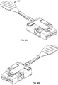
- Figs. 4(A) and 4(B) show the module of Fig. 1 in the unactuated and actuated state, respectively.
- the arcuate portions 110 of flanges 108 pivot in the recess 109 to rotate the contacting portion 107 upward and into the resilient latch 105.
- the resilience of the latch is sufficient to rotate the contacting portion 107 back toward the housing and return the actuator to its unactuated state as shown in Fig. 4(A) .
- module 500 like module 100, has a front/rear and top/bottom orientation, comprises a housing 501 with a connector 502 disposed at the front end, and a resilient latch 503 having a secured end 504 secured to the housing, and a free end 505 forward of the secured end.
- the actuator 506 is also slidably attached to the housing under the latch 503.
- actuator 506 does not have flanges as in the embodiment of Fig. 1 . Rather, the contact portion 507 urges against an inclined portion 550 of the latch.
- the inclined portion slopes toward the housing from front to back as shown. Thus, as the contact portion moves rearward and contacts the inclined portion 550, the latch 503 is urged away from the housing.
- the actuator does not substantially extend above the housing top when the actuator is in an actuated state. This is important in high connector density applications.
- one embodiment of the invention also includes a tab 601 connected to the actuator.
- the tab extends from the rear of the module, clear of the cable(s) attached to the rear of the module (if any), thus making the actuation of the actuator easier.
- the tab is discrete from the actuator, while in another embodiment, the tab is integral with the actuator. In one embodiment, the tab is flexible.
Landscapes
- Details Of Connecting Devices For Male And Female Coupling (AREA)
- Connector Housings Or Holding Contact Members (AREA)
Description
- This disclosure relates to a module extraction system, and more specifically to a connector module having an actuatable latch for high density connector configurations.
- In high-density connector configurations, it is often difficult to extract a connector once it is plugged in because the connector's latching mechanism is not accessible. For example, the latching mechanism is often located on the top or bottom of the connector modular such that, when the connectors are densely packed, with one on top of the other, access to the latching mechanism on the top/bottom of the module is significantly restricted if not altogether blocked. Accordingly, to remove a particular module, the other modules in a column must be removed to provide access to the latching mechanism of a particular module, or special tooling must be employed to engage the latching mechanism.
-
EP 2741377 , on which the preamble of claim 1 is based, discloses a module having a housing with a connector at a front end of the housing for interengaging with a mating connector. A resilient latch is secured to the housing. A free end of the latch is biased towards the housing and has a latch-eye to engage a latch-notch of the mating connector. A lever is disposed under the latch and comprises a pair of lateral flanges pivotally attached to the housing. The lever is attached to a pull-tab, and when the pull-tab is pulled rearward, a contact portion of the lever contacts the latch as the flanges of the lever pivot relative to the housing. This contact causes the free end of the latch to move away from the housing and thus free the latch-eye from the latch-notch. - Applicants have identified a need to provide a convenient mechanism to withdraw a plug from a high density array of connectors without the need to remove adjacent modules or use special tooling. The present invention fulfills this need among others.
- The following presents a simplified summary of the invention in order to provide a basic understanding of some aspects of the invention. This summary is not an extensive overview of the invention. It is not intended to identify key/critical elements of the invention or to delineate the scope of the invention. Its sole purpose is to present some concepts of the invention in a simplified form as a prelude to the more detailed description that is presented later.
- According to the invention there is provided a module having a front/rear and top/bottom orientation, said module comprising: a housing having front and rear ends, and recesses; a connector at said front end of said housing for interengaging with a mating connector having a purchase point; a resilient latch having a secured end secured to said housing, and a free end forward of said secured end, said free end being biased toward said housing and configured to releasably engage said purchase point; and an actuator moveably attached to said housing, said actuator being disposed under said latch and having a contact portion which is configured to contact said latch as said actuator is pulled rearward to urge said latch away from said housing, thereby freeing said free end from said purchase point, wherein said actuator is pivotally attached to said housing, and wherein said actuator comprises lateral flanges about which said contact portion of said actuator is configured to pivot when said actuator is pulled rearward, said flanges received by said recesses, and said flanges comprising an arcuate portion, characterized in that said arcuate portion functions as a pivot point; and said recesses are larger than said flanges to accommodate pivoting.
- The module may comprise a second connector at the second end of the housing.
-
-
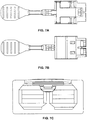
Figs. 1-3 show one embodiment of the latch actuator module of the present invention. -
Figs. 4(A) and 4(B) show the module ofFig. 1 in the unactuated and actuated state, respectively. -
Fig. 5 shows an arrangement of an actuator module included for background information only. -
Figs. 6(A)-(B) show one embodiment of the connector module of the present invention from top right and top left perspective views, respectively. -
Figs. 6(C)-(D) show the embodiment ofFigs. 6(A)-(B) from bottom right and bottom left perspective views, respectively. -
Figs. 7(A)-(B) show the embodiment ofFigs. 6(A)-(B) from the top and bottom, respectively. -
Figs. 7(C)-(D) show the embodiment ofFigs. 6(A)-(B) from the front and back, respectively. -
Figs. 7(E)-(F) show the embodiment ofFigs. 6(A)-(B) from the right and left side, respectively. - Referring to
Figs. 1-3 , amodule 100 having one embodiment of the extraction mechanism of the present invention is shown. Themodule 100 has a front/rear and top/bottom orientation, and comprises ahousing 101 having front andrear ends connector 102 is disposed at the front end of the housing for interengaging with a mating connector having purchase point (not shown). The module also comprises aresilient latch 103 having a securedend 104 secured to the housing, and afree end 105 forward of the secured end. The free end is biased toward the housing and configured to releasibly engage the purchase point. The module also comprises anactuator 106 moveably attached to the housing. The actuator is disposed under thelatch 103 and has acontact portion 107, which contacts the latch as the actuator is pulled rearward to urge the latch away from the housing, thereby freeing the free end from the purchase point. - It should be understood that the purchase point may be any known structure on the mating connector for interengaging with the free end of the latch to hold the module in place. A purchase point, in this context, is well known to those of skill in the art, and includes, for example, a recess (e.g., groove) or a protrusion (e.g., ridge). The free end is configured to interengage with the purchase point. Again, such configurations are well known to those of skill in the art. For example, the free end may comprise a hook to hook/latch onto a protrusion or recess on the mating connector, or the free end may define an orifice to receive a protrusion. Still other embodiments will be known or obvious to one of skill in the art in light of this disclosure.
- As used herein, the module may be any modular device having at least one connector. Generally, although not necessarily, the modular device is one which is subject to high-density connector configurations. In one embodiment, the module has one or more connectors at the front end and one or more connectors at the back end. The connectors and the housing may be discrete or integrally molded.
- The actuator is pivotally attached to the housing, and the actuator comprises
lateral flanges 108 about which thecontact portion 107 of the actuator pivots when the actuator is pulled rearward. In particular, the flanges comprise anarcuate portion 110 to function as a pivot point, and the housing comprisesrecesses 109 to receive the flanges. The recesses are larger than the flanges to allow the flanges room to pivot. -
Figs. 4(A) and 4(B) show the module ofFig. 1 in the unactuated and actuated state, respectively. Specifically, referring toFig. 4(B) , as one pulls theactuator 106 rearward, thearcuate portions 110 offlanges 108 pivot in therecess 109 to rotate the contactingportion 107 upward and into theresilient latch 105. In one embodiment, the resilience of the latch is sufficient to rotate the contactingportion 107 back toward the housing and return the actuator to its unactuated state as shown inFig. 4(A) . - An alternative arrangement of the actuator included for background information is illustrated in
Fig. 5 , wherein the actuator is slidably attached to the housing. Specifically,module 500, likemodule 100, has a front/rear and top/bottom orientation, comprises ahousing 501 with aconnector 502 disposed at the front end, and aresilient latch 503 having a securedend 504 secured to the housing, and afree end 505 forward of the secured end. Theactuator 506 is also slidably attached to the housing under thelatch 503. However, in this arrangement,actuator 506 does not have flanges as in the embodiment ofFig. 1 . Rather, thecontact portion 507 urges against aninclined portion 550 of the latch. The inclined portion slopes toward the housing from front to back as shown. Thus, as the contact portion moves rearward and contacts theinclined portion 550, thelatch 503 is urged away from the housing. - In the embodiment of
Fig. 1 and the arrangement ofFig. 5 , the actuator does not substantially extend above the housing top when the actuator is in an actuated state. This is important in high connector density applications. - To aid in actuating the actuator, one embodiment of the invention also includes a
tab 601 connected to the actuator. The tab extends from the rear of the module, clear of the cable(s) attached to the rear of the module (if any), thus making the actuation of the actuator easier. In one embodiment, the tab is discrete from the actuator, while in another embodiment, the tab is integral with the actuator. In one embodiment, the tab is flexible.
Claims (6)
- A module (100) having a front/rear and top/bottom orientation, said module comprising:a housing (101) having front and rear ends (101a, 101b), and recesses (109);a connector (102) at said front end (101a) of said housing (101) for interengaging with a mating connector having a purchase point;a resilient latch (103) having a secured end (104) secured to said housing (101), and a free end (105) forward of said secured end (104), said free end (105) being biased toward said housing (101) and configured to releasably engage said purchase point; andan actuator (106) moveably attached to said housing (101), said actuator (106) being disposed under said latch (103) and having a contact portion (107) which is configured to contact said latch (103) as said actuator (106) is pulled rearward to urge said latch (103) away from said housing (101), thereby freeing said free end (105) from said purchase point, wherein said actuator (106) is pivotally attached to said housing (101), and wherein said actuator (106) comprises lateral flanges (108) about which said contact portion (107) of said actuator (106) is configured to pivot when said actuator (106) is pulled rearward, said flanges (108) received by said recesses (109), and said flanges (108) comprising an arcuate portion (110),characterized in thatsaid arcuate portion (110) functions as a pivot point; andsaid recesses (109) are larger than said flanges (108) to accommodate pivoting.
- The module of claim 1, further comprising a tab (601) connected to said actuator (106).
- The module of claim 2, wherein said tab (601) is discrete from said actuator (106).
- The module of claim 2, wherein said tab is integral with said actuator.
- The module of any preceding claim, further comprising a second connector at said rear end (101b) of said housing (101).
- The module of any preceding claim, wherein said connector (102) and said housing (101) are integrally molded.
Applications Claiming Priority (2)
| Application Number | Priority Date | Filing Date | Title |
|---|---|---|---|
| US201562112446P | 2015-02-05 | 2015-02-05 | |
| US14/832,787 US9601868B2 (en) | 2015-02-05 | 2015-08-21 | Module latch actuator |
Publications (2)
| Publication Number | Publication Date |
|---|---|
| EP3054539A1 EP3054539A1 (en) | 2016-08-10 |
| EP3054539B1 true EP3054539B1 (en) | 2018-07-04 |
Family
ID=55272357
Family Applications (1)
| Application Number | Title | Priority Date | Filing Date |
|---|---|---|---|
| EP16153472.2A Active EP3054539B1 (en) | 2015-02-05 | 2016-01-29 | Module latch actuator |
Country Status (3)
| Country | Link |
|---|---|
| US (1) | US9601868B2 (en) |
| EP (1) | EP3054539B1 (en) |
| CN (1) | CN105870717B (en) |
Families Citing this family (6)
| Publication number | Priority date | Publication date | Assignee | Title |
|---|---|---|---|---|
| USD871340S1 (en) * | 2015-08-21 | 2019-12-31 | Te Connectivity Nederland B.V. | Module latch actuator |
| JP7047457B2 (en) * | 2018-02-27 | 2022-04-05 | 沖電気工業株式会社 | connector |
| CN111740272B (en) * | 2019-03-25 | 2021-11-26 | 珠海保税区光联通讯技术有限公司 | Connector with a locking member |
| US10873157B1 (en) * | 2020-01-03 | 2020-12-22 | TE Connectivity Services Gmbh | Pull tab for a plug connector |
| CN111326886B (en) * | 2020-04-08 | 2021-11-09 | 东莞立讯技术有限公司 | Pull belt unlocking structure and connector |
| US12500378B2 (en) * | 2022-12-23 | 2025-12-16 | Yamaichi Electronics Co., Ltd. | Plug connector and receptacle connector, and method of extracting plug connector |
Family Cites Families (10)
| Publication number | Priority date | Publication date | Assignee | Title |
|---|---|---|---|---|
| US7281937B2 (en) * | 2005-02-18 | 2007-10-16 | Molex Incorporated | Low profile latching connector |
| US7413473B2 (en) * | 2005-08-26 | 2008-08-19 | Hon Hai Precision Ind. Co., Ltd. | Cable connector assembly with EMI gasket |
| US7828579B2 (en) | 2007-08-28 | 2010-11-09 | Kingconn Technology Co., Ltd. | Latch locking type connector |
| US7540755B1 (en) * | 2008-01-18 | 2009-06-02 | Hon Hai Precision Ind. Co., Ltd. | Electrical connector assembly with improved latching mechanism |
| US7534125B1 (en) | 2008-02-26 | 2009-05-19 | Tyco Electronics Corporation | Electrical connector having a multi-directional latching mechanism |
| CN201927841U (en) * | 2010-12-10 | 2011-08-10 | 富士康(昆山)电脑接插件有限公司 | Cable connector |
| CN202042701U (en) * | 2010-12-30 | 2011-11-16 | 富士康(昆山)电脑接插件有限公司 | Connector |
| CN102769230B (en) * | 2011-05-06 | 2016-02-03 | 富士康(昆山)电脑接插件有限公司 | Pin connector |
| EP2741377A1 (en) | 2012-12-06 | 2014-06-11 | Tyco Electronics Nederland B.V. | Cable connector and connector assembly |
| CN104716507B (en) * | 2013-12-11 | 2018-08-31 | 富士康(昆山)电脑接插件有限公司 | Connector and its component |
-
2015
- 2015-08-21 US US14/832,787 patent/US9601868B2/en active Active
-
2016
- 2016-01-29 EP EP16153472.2A patent/EP3054539B1/en active Active
- 2016-02-05 CN CN201610081967.6A patent/CN105870717B/en active Active
Non-Patent Citations (1)
| Title |
|---|
| None * |
Also Published As
| Publication number | Publication date |
|---|---|
| CN105870717A (en) | 2016-08-17 |
| US9601868B2 (en) | 2017-03-21 |
| US20160233612A1 (en) | 2016-08-11 |
| EP3054539A1 (en) | 2016-08-10 |
| CN105870717B (en) | 2019-11-05 |
Similar Documents
| Publication | Publication Date | Title |
|---|---|---|
| EP2859625B1 (en) | Connector assembly and connector product | |
| EP3054539A1 (en) | Module latch actuator | |
| US7402070B1 (en) | Latch mechanism with spring back function | |
| EP1771925B1 (en) | Electrical connector latch | |
| KR100964442B1 (en) | Connector Locator and Latch | |
| US7513693B2 (en) | Fiber optic connector release mechanism | |
| US8231400B2 (en) | Latch for a cable assembly | |
| US5741150A (en) | Unitary spring latch for an electrical connector assembly | |
| EP0624922B1 (en) | Connector | |
| EP1065756B1 (en) | Locking and unlocking mechanism of cable connector and method for locking and unlocking | |
| EP4002604B1 (en) | Connector | |
| US7857650B1 (en) | Electrical connector assembly with latching mechanism | |
| JP3996168B2 (en) | Connector boot and connector assembly | |
| EP1100160B1 (en) | Electrical connector assembly with improved camming system | |
| US10547142B1 (en) | Latch assembly for a plug connector | |
| US20180076587A1 (en) | Dual connector system | |
| US8142229B1 (en) | Card connector with cam feature for facilitating insertion of a card | |
| EP1054481A1 (en) | A connector | |
| US7927117B2 (en) | Electrical card connector | |
| EP2426790A1 (en) | Connector and connector assembly | |
| US8246366B2 (en) | Electrical card connector with a stop member for temporarily preventing a card from ejecting from the card release position | |
| EP3734770B1 (en) | Electrical connector having position holder | |
| US8303321B1 (en) | Card connector anti-misinserting a micro SD card | |
| US8303322B1 (en) | Card connector anti-misinserting a micro SD card | |
| JP7389407B2 (en) | card edge connector |
Legal Events
| Date | Code | Title | Description |
|---|---|---|---|
| PUAI | Public reference made under article 153(3) epc to a published international application that has entered the european phase |
Free format text: ORIGINAL CODE: 0009012 |
|
| AK | Designated contracting states |
Kind code of ref document: A1 Designated state(s): AL AT BE BG CH CY CZ DE DK EE ES FI FR GB GR HR HU IE IS IT LI LT LU LV MC MK MT NL NO PL PT RO RS SE SI SK SM TR |
|
| AX | Request for extension of the european patent |
Extension state: BA ME |
|
| RAP3 | Party data changed (applicant data changed or rights of an application transferred) |
Owner name: TYCO ELECTRONICS SVENSKA HOLDINGS AB Owner name: TE CONNECTIVITY NEDERLAND B.V. Owner name: TYCO ELECTRONICS (SHANGHAI) CO. LTD. |
|
| STAA | Information on the status of an ep patent application or granted ep patent |
Free format text: STATUS: REQUEST FOR EXAMINATION WAS MADE |
|
| RIN1 | Information on inventor provided before grant (corrected) |
Inventor name: DRIJFHOUT, TEKKE Inventor name: BARREFELT, RICKARD Inventor name: SMITS, JOHAN Inventor name: ZHANG, ZHICHENG |
|
| 17P | Request for examination filed |
Effective date: 20170131 |
|
| RBV | Designated contracting states (corrected) |
Designated state(s): AL AT BE BG CH CY CZ DE DK EE ES FI FR GB GR HR HU IE IS IT LI LT LU LV MC MK MT NL NO PL PT RO RS SE SI SK SM TR |
|
| STAA | Information on the status of an ep patent application or granted ep patent |
Free format text: STATUS: EXAMINATION IS IN PROGRESS |
|
| 17Q | First examination report despatched |
Effective date: 20170620 |
|
| GRAP | Despatch of communication of intention to grant a patent |
Free format text: ORIGINAL CODE: EPIDOSNIGR1 |
|
| STAA | Information on the status of an ep patent application or granted ep patent |
Free format text: STATUS: GRANT OF PATENT IS INTENDED |
|
| INTG | Intention to grant announced |
Effective date: 20180207 |
|
| RIN1 | Information on inventor provided before grant (corrected) |
Inventor name: DRIJFHOUT, TEKKE Inventor name: SMITS, JOHAN Inventor name: ZHANG, ZHICHENG Inventor name: BARREFELT, RICKARD |
|
| RAP1 | Party data changed (applicant data changed or rights of an application transferred) |
Owner name: TE CONNECTIVITY NEDERLAND B.V. Owner name: TYCO ELECTRONICS (SHANGHAI) CO. LTD. Owner name: TYCO ELECTRONICS SVENSKA AB |
|
| GRAJ | Information related to disapproval of communication of intention to grant by the applicant or resumption of examination proceedings by the epo deleted |
Free format text: ORIGINAL CODE: EPIDOSDIGR1 |
|
| STAA | Information on the status of an ep patent application or granted ep patent |
Free format text: STATUS: EXAMINATION IS IN PROGRESS |
|
| GRAR | Information related to intention to grant a patent recorded |
Free format text: ORIGINAL CODE: EPIDOSNIGR71 |
|
| GRAS | Grant fee paid |
Free format text: ORIGINAL CODE: EPIDOSNIGR3 |
|
| STAA | Information on the status of an ep patent application or granted ep patent |
Free format text: STATUS: GRANT OF PATENT IS INTENDED |
|
| GRAA | (expected) grant |
Free format text: ORIGINAL CODE: 0009210 |
|
| STAA | Information on the status of an ep patent application or granted ep patent |
Free format text: STATUS: THE PATENT HAS BEEN GRANTED |
|
| INTC | Intention to grant announced (deleted) | ||
| AK | Designated contracting states |
Kind code of ref document: B1 Designated state(s): AL AT BE BG CH CY CZ DE DK EE ES FI FR GB GR HR HU IE IS IT LI LT LU LV MC MK MT NL NO PL PT RO RS SE SI SK SM TR |
|
| INTG | Intention to grant announced |
Effective date: 20180528 |
|
| REG | Reference to a national code |
Ref country code: GB Ref legal event code: FG4D |
|
| REG | Reference to a national code |
Ref country code: CH Ref legal event code: EP |
|
| REG | Reference to a national code |
Ref country code: AT Ref legal event code: REF Ref document number: 1015517 Country of ref document: AT Kind code of ref document: T Effective date: 20180715 |
|
| REG | Reference to a national code |
Ref country code: IE Ref legal event code: FG4D |
|
| REG | Reference to a national code |
Ref country code: DE Ref legal event code: R096 Ref document number: 602016003864 Country of ref document: DE |
|
| REG | Reference to a national code |
Ref country code: SE Ref legal event code: TRGR |
|
| REG | Reference to a national code |
Ref country code: NL Ref legal event code: MP Effective date: 20180704 |
|
| REG | Reference to a national code |
Ref country code: EE Ref legal event code: FG4A Ref document number: E016114 Country of ref document: EE Effective date: 20180921 |
|
| REG | Reference to a national code |
Ref country code: LT Ref legal event code: MG4D |
|
| REG | Reference to a national code |
Ref country code: AT Ref legal event code: MK05 Ref document number: 1015517 Country of ref document: AT Kind code of ref document: T Effective date: 20180704 |
|
| PG25 | Lapsed in a contracting state [announced via postgrant information from national office to epo] |
Ref country code: NL Free format text: LAPSE BECAUSE OF FAILURE TO SUBMIT A TRANSLATION OF THE DESCRIPTION OR TO PAY THE FEE WITHIN THE PRESCRIBED TIME-LIMIT Effective date: 20180704 |
|
| PG25 | Lapsed in a contracting state [announced via postgrant information from national office to epo] |
Ref country code: CZ Free format text: LAPSE BECAUSE OF FAILURE TO SUBMIT A TRANSLATION OF THE DESCRIPTION OR TO PAY THE FEE WITHIN THE PRESCRIBED TIME-LIMIT Effective date: 20180704 Ref country code: PL Free format text: LAPSE BECAUSE OF FAILURE TO SUBMIT A TRANSLATION OF THE DESCRIPTION OR TO PAY THE FEE WITHIN THE PRESCRIBED TIME-LIMIT Effective date: 20180704 Ref country code: BG Free format text: LAPSE BECAUSE OF FAILURE TO SUBMIT A TRANSLATION OF THE DESCRIPTION OR TO PAY THE FEE WITHIN THE PRESCRIBED TIME-LIMIT Effective date: 20181004 Ref country code: LT Free format text: LAPSE BECAUSE OF FAILURE TO SUBMIT A TRANSLATION OF THE DESCRIPTION OR TO PAY THE FEE WITHIN THE PRESCRIBED TIME-LIMIT Effective date: 20180704 Ref country code: GR Free format text: LAPSE BECAUSE OF FAILURE TO SUBMIT A TRANSLATION OF THE DESCRIPTION OR TO PAY THE FEE WITHIN THE PRESCRIBED TIME-LIMIT Effective date: 20181005 Ref country code: NO Free format text: LAPSE BECAUSE OF FAILURE TO SUBMIT A TRANSLATION OF THE DESCRIPTION OR TO PAY THE FEE WITHIN THE PRESCRIBED TIME-LIMIT Effective date: 20181004 Ref country code: AT Free format text: LAPSE BECAUSE OF FAILURE TO SUBMIT A TRANSLATION OF THE DESCRIPTION OR TO PAY THE FEE WITHIN THE PRESCRIBED TIME-LIMIT Effective date: 20180704 Ref country code: IS Free format text: LAPSE BECAUSE OF FAILURE TO SUBMIT A TRANSLATION OF THE DESCRIPTION OR TO PAY THE FEE WITHIN THE PRESCRIBED TIME-LIMIT Effective date: 20181104 Ref country code: RS Free format text: LAPSE BECAUSE OF FAILURE TO SUBMIT A TRANSLATION OF THE DESCRIPTION OR TO PAY THE FEE WITHIN THE PRESCRIBED TIME-LIMIT Effective date: 20180704 |
|
| PG25 | Lapsed in a contracting state [announced via postgrant information from national office to epo] |
Ref country code: AL Free format text: LAPSE BECAUSE OF FAILURE TO SUBMIT A TRANSLATION OF THE DESCRIPTION OR TO PAY THE FEE WITHIN THE PRESCRIBED TIME-LIMIT Effective date: 20180704 Ref country code: ES Free format text: LAPSE BECAUSE OF FAILURE TO SUBMIT A TRANSLATION OF THE DESCRIPTION OR TO PAY THE FEE WITHIN THE PRESCRIBED TIME-LIMIT Effective date: 20180704 Ref country code: HR Free format text: LAPSE BECAUSE OF FAILURE TO SUBMIT A TRANSLATION OF THE DESCRIPTION OR TO PAY THE FEE WITHIN THE PRESCRIBED TIME-LIMIT Effective date: 20180704 Ref country code: LV Free format text: LAPSE BECAUSE OF FAILURE TO SUBMIT A TRANSLATION OF THE DESCRIPTION OR TO PAY THE FEE WITHIN THE PRESCRIBED TIME-LIMIT Effective date: 20180704 |
|
| REG | Reference to a national code |
Ref country code: DE Ref legal event code: R097 Ref document number: 602016003864 Country of ref document: DE |
|
| PG25 | Lapsed in a contracting state [announced via postgrant information from national office to epo] |
Ref country code: IT Free format text: LAPSE BECAUSE OF FAILURE TO SUBMIT A TRANSLATION OF THE DESCRIPTION OR TO PAY THE FEE WITHIN THE PRESCRIBED TIME-LIMIT Effective date: 20180704 Ref country code: RO Free format text: LAPSE BECAUSE OF FAILURE TO SUBMIT A TRANSLATION OF THE DESCRIPTION OR TO PAY THE FEE WITHIN THE PRESCRIBED TIME-LIMIT Effective date: 20180704 |
|
| PLBE | No opposition filed within time limit |
Free format text: ORIGINAL CODE: 0009261 |
|
| STAA | Information on the status of an ep patent application or granted ep patent |
Free format text: STATUS: NO OPPOSITION FILED WITHIN TIME LIMIT |
|
| PG25 | Lapsed in a contracting state [announced via postgrant information from national office to epo] |
Ref country code: SK Free format text: LAPSE BECAUSE OF FAILURE TO SUBMIT A TRANSLATION OF THE DESCRIPTION OR TO PAY THE FEE WITHIN THE PRESCRIBED TIME-LIMIT Effective date: 20180704 Ref country code: SM Free format text: LAPSE BECAUSE OF FAILURE TO SUBMIT A TRANSLATION OF THE DESCRIPTION OR TO PAY THE FEE WITHIN THE PRESCRIBED TIME-LIMIT Effective date: 20180704 Ref country code: DK Free format text: LAPSE BECAUSE OF FAILURE TO SUBMIT A TRANSLATION OF THE DESCRIPTION OR TO PAY THE FEE WITHIN THE PRESCRIBED TIME-LIMIT Effective date: 20180704 |
|
| 26N | No opposition filed |
Effective date: 20190405 |
|
| PG25 | Lapsed in a contracting state [announced via postgrant information from national office to epo] |
Ref country code: MC Free format text: LAPSE BECAUSE OF FAILURE TO SUBMIT A TRANSLATION OF THE DESCRIPTION OR TO PAY THE FEE WITHIN THE PRESCRIBED TIME-LIMIT Effective date: 20180704 Ref country code: SI Free format text: LAPSE BECAUSE OF FAILURE TO SUBMIT A TRANSLATION OF THE DESCRIPTION OR TO PAY THE FEE WITHIN THE PRESCRIBED TIME-LIMIT Effective date: 20180704 |
|
| REG | Reference to a national code |
Ref country code: CH Ref legal event code: PL |
|
| PG25 | Lapsed in a contracting state [announced via postgrant information from national office to epo] |
Ref country code: LU Free format text: LAPSE BECAUSE OF NON-PAYMENT OF DUE FEES Effective date: 20190129 |
|
| REG | Reference to a national code |
Ref country code: BE Ref legal event code: MM Effective date: 20190131 |
|
| REG | Reference to a national code |
Ref country code: IE Ref legal event code: MM4A |
|
| PG25 | Lapsed in a contracting state [announced via postgrant information from national office to epo] |
Ref country code: BE Free format text: LAPSE BECAUSE OF NON-PAYMENT OF DUE FEES Effective date: 20190131 |
|
| PG25 | Lapsed in a contracting state [announced via postgrant information from national office to epo] |
Ref country code: LI Free format text: LAPSE BECAUSE OF NON-PAYMENT OF DUE FEES Effective date: 20190131 Ref country code: CH Free format text: LAPSE BECAUSE OF NON-PAYMENT OF DUE FEES Effective date: 20190131 |
|
| PG25 | Lapsed in a contracting state [announced via postgrant information from national office to epo] |
Ref country code: IE Free format text: LAPSE BECAUSE OF NON-PAYMENT OF DUE FEES Effective date: 20190129 |
|
| PG25 | Lapsed in a contracting state [announced via postgrant information from national office to epo] |
Ref country code: TR Free format text: LAPSE BECAUSE OF FAILURE TO SUBMIT A TRANSLATION OF THE DESCRIPTION OR TO PAY THE FEE WITHIN THE PRESCRIBED TIME-LIMIT Effective date: 20180704 |
|
| PG25 | Lapsed in a contracting state [announced via postgrant information from national office to epo] |
Ref country code: PT Free format text: LAPSE BECAUSE OF FAILURE TO SUBMIT A TRANSLATION OF THE DESCRIPTION OR TO PAY THE FEE WITHIN THE PRESCRIBED TIME-LIMIT Effective date: 20181104 Ref country code: MT Free format text: LAPSE BECAUSE OF NON-PAYMENT OF DUE FEES Effective date: 20190129 |
|
| PG25 | Lapsed in a contracting state [announced via postgrant information from national office to epo] |
Ref country code: CY Free format text: LAPSE BECAUSE OF FAILURE TO SUBMIT A TRANSLATION OF THE DESCRIPTION OR TO PAY THE FEE WITHIN THE PRESCRIBED TIME-LIMIT Effective date: 20180704 |
|
| PG25 | Lapsed in a contracting state [announced via postgrant information from national office to epo] |
Ref country code: HU Free format text: LAPSE BECAUSE OF FAILURE TO SUBMIT A TRANSLATION OF THE DESCRIPTION OR TO PAY THE FEE WITHIN THE PRESCRIBED TIME-LIMIT; INVALID AB INITIO Effective date: 20160129 |
|
| PG25 | Lapsed in a contracting state [announced via postgrant information from national office to epo] |
Ref country code: MK Free format text: LAPSE BECAUSE OF FAILURE TO SUBMIT A TRANSLATION OF THE DESCRIPTION OR TO PAY THE FEE WITHIN THE PRESCRIBED TIME-LIMIT Effective date: 20180704 |
|
| PGFP | Annual fee paid to national office [announced via postgrant information from national office to epo] |
Ref country code: GB Payment date: 20251211 Year of fee payment: 11 |
|
| PGFP | Annual fee paid to national office [announced via postgrant information from national office to epo] |
Ref country code: FI Payment date: 20251230 Year of fee payment: 11 |
|
| PGFP | Annual fee paid to national office [announced via postgrant information from national office to epo] |
Ref country code: FR Payment date: 20251208 Year of fee payment: 11 |
|
| PGFP | Annual fee paid to national office [announced via postgrant information from national office to epo] |
Ref country code: SE Payment date: 20251210 Year of fee payment: 11 |
|
| PGFP | Annual fee paid to national office [announced via postgrant information from national office to epo] |
Ref country code: EE Payment date: 20251229 Year of fee payment: 11 |
|
| PGFP | Annual fee paid to national office [announced via postgrant information from national office to epo] |
Ref country code: DE Payment date: 20251203 Year of fee payment: 11 |