EP3054473B1 - Trapping ion mobility spectrometer with parallel accumulation - Google Patents
Trapping ion mobility spectrometer with parallel accumulation Download PDFInfo
- Publication number
- EP3054473B1 EP3054473B1 EP16152865.8A EP16152865A EP3054473B1 EP 3054473 B1 EP3054473 B1 EP 3054473B1 EP 16152865 A EP16152865 A EP 16152865A EP 3054473 B1 EP3054473 B1 EP 3054473B1
- Authority
- EP
- European Patent Office
- Prior art keywords
- ions
- ion
- ion mobility
- trapping
- field
- Prior art date
- Legal status (The legal status is an assumption and is not a legal conclusion. Google has not performed a legal analysis and makes no representation as to the accuracy of the status listed.)
- Active
Links
Images

Classifications
-
- G—PHYSICS
- G01—MEASURING; TESTING
- G01N—INVESTIGATING OR ANALYSING MATERIALS BY DETERMINING THEIR CHEMICAL OR PHYSICAL PROPERTIES
- G01N27/00—Investigating or analysing materials by the use of electric, electrochemical, or magnetic means
- G01N27/62—Investigating or analysing materials by the use of electric, electrochemical, or magnetic means by investigating the ionisation of gases, e.g. aerosols; by investigating electric discharges, e.g. emission of cathode
- G01N27/622—Ion mobility spectrometry
-
- H—ELECTRICITY
- H01—ELECTRIC ELEMENTS
- H01J—ELECTRIC DISCHARGE TUBES OR DISCHARGE LAMPS
- H01J49/00—Particle spectrometers or separator tubes
- H01J49/0027—Methods for using particle spectrometers
- H01J49/0031—Step by step routines describing the use of the apparatus
-
- H—ELECTRICITY
- H01—ELECTRIC ELEMENTS
- H01J—ELECTRIC DISCHARGE TUBES OR DISCHARGE LAMPS
- H01J49/00—Particle spectrometers or separator tubes
- H01J49/004—Combinations of spectrometers, tandem spectrometers, e.g. MS/MS, MSn
-
- H—ELECTRICITY
- H01—ELECTRIC ELEMENTS
- H01J—ELECTRIC DISCHARGE TUBES OR DISCHARGE LAMPS
- H01J49/00—Particle spectrometers or separator tubes
- H01J49/02—Details
-
- H—ELECTRICITY
- H01—ELECTRIC ELEMENTS
- H01J—ELECTRIC DISCHARGE TUBES OR DISCHARGE LAMPS
- H01J49/00—Particle spectrometers or separator tubes
- H01J49/02—Details
- H01J49/04—Arrangements for introducing or extracting samples to be analysed, e.g. vacuum locks; Arrangements for external adjustment of electron- or ion-optical components
-
- H—ELECTRICITY
- H01—ELECTRIC ELEMENTS
- H01J—ELECTRIC DISCHARGE TUBES OR DISCHARGE LAMPS
- H01J49/00—Particle spectrometers or separator tubes
- H01J49/02—Details
- H01J49/04—Arrangements for introducing or extracting samples to be analysed, e.g. vacuum locks; Arrangements for external adjustment of electron- or ion-optical components
- H01J49/0459—Arrangements for introducing or extracting samples to be analysed, e.g. vacuum locks; Arrangements for external adjustment of electron- or ion-optical components for solid samples
-
- H—ELECTRICITY
- H01—ELECTRIC ELEMENTS
- H01J—ELECTRIC DISCHARGE TUBES OR DISCHARGE LAMPS
- H01J49/00—Particle spectrometers or separator tubes
- H01J49/02—Details
- H01J49/06—Electron- or ion-optical arrangements
-
- H—ELECTRICITY
- H01—ELECTRIC ELEMENTS
- H01J—ELECTRIC DISCHARGE TUBES OR DISCHARGE LAMPS
- H01J49/00—Particle spectrometers or separator tubes
- H01J49/02—Details
- H01J49/06—Electron- or ion-optical arrangements
- H01J49/061—Ion deflecting means, e.g. ion gates
Definitions
- the invention relates to devices and methods for the acquisition of mass spectra of ions separated by their mobility.
- TMS trapped ion mobility spectrometer
- the length of the essential mobility separation unit, the separator tunnel amounts to about five centimeters only, not counting additional entrance and exit funnels.
- the separation of ions according to their mobilities is based upon a gas flow in the cylindrical separator tunnel which drives the ions from an ion source in an accumulation phase against a counter-acting electric DC field barrier while the ions are radially confined by a quadrupolar RF field. After shutting down the delivery of further ions, a scan phase starts, in which the electric DC field barrier is steadily decreased.
- Ions are driven in the scan phase by the gas flow over the decreasing electric DC field barrier, thereby releasing, successively, ions from low mobilities to higher and higher mobilities from being trapped by the barrier.
- the ions can be detected in an ion detector, resulting in a mobility spectrum.
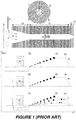
- FIG. 1 schematically shows a preferred design and operation of a trapping ion mobility spectrometer as described in US 7,838,826 B1 .
- the tube-like separator tunnel (11) between entrance funnel (10) and exit funnel (12) amount to only 48 millimeters in length; the inner diameter amounts to eight millimeters.
- the ion mobility separator tunnel (11) consists of a series of segmented diaphragms with quadrant electrodes (1), (2), (3), and (4), for generating a quadrupolar RF field. Ions (6) from a source (not shown) are introduced by capillary (8) together with a gas stream (7) into a first vacuum chamber.
- a repeller plate (9) directs the ions into the funnel (10); the gas flow (14) drives the ions into the separator tunnel (11).
- electric field profiles E(z) along the z-axis are shown for three phases of operation: In the accumulation phase (A) ions are blown by the gas flow (16) against the rising edge of the electric field profile between z locations (20) and (23). In a trap phase (B) of only one to two milliseconds, the inflow of ions is stopped and ions assume their equilibrium position on the rising edge according to their mobility.
- the steadily decreasing profile voltage in the scan phase (C) releases ions in the order of increasing ion mobility over the plateau of the electric field between locations (23) and (24) and through the exit funnel towards an ion detector.
- the ions may be measured by a mass spectrometer, e.g. a time-of-flight mass spectrometer, resulting in a two-dimensional mass-mobility spectrum.
- a mass spectrometer e.g. a time-of-flight mass spectrometer
- the invention is defined by a method according to claim 1.
- the utilization rate is also termed "duty cycle" here. According to the present invention, the duty cycle can be close to 100 percent when no ions get lost in the RF ion trap (accumulation unit) and in the trapping ion mobility separator (scan unit).
- the ions are radially confined in the trapping ion mobility separator by a quadrupolar RF field.
- the ions can be accumulated in a RF funnel located between the ion source and the trapping ion mobility separator wherein the field at the exit of the RF funnel is preferably adjusted to the quadrupolar RF field at the entrance of the trapping ion mobility separator.
- the ions are preferably accumulated in a linear RF trap having a quadrupolar RF field for radially confining the ions.
- RF fields with higher multipoles can further enhance the ion storage capacity of the linear RF ion trap, but it is more elaborate to couple them with the preferred quadrupolar RF field of the trapping ion mobility separator.
- steps (b) and (c) are repeated to acquire a series of ion mobility spectra, in particular a time series of ion mobility spectra.
- the ion density can be determined as a function of ion mobility from one or more preceding ion mobility spectra and then used to adjust the electric field profile of the rising edge of the first electric DC field barrier in order to minimize ion losses in the trapping ion mobility separator during steps (b) and (c).
- the electric field profile is preferably adjusted such that ions are decompressed where a high ion density is determined or where ions of interest are determined.
- the ions can be axially trapped at the exit of the RF ion trap by applying a repelling DC potential to an exit electrode of the RF ion trap during steps (a) and (c).
- the accumulated ions are pushed by the gas flow against a rising edge of a second axial electric DC field barrier located in the RF ion trap.
- the height of the second DC field barrier is adjusted such that ions are trapped along the rising edge of the second DC field barrier and spatially separated according to ion mobility.
- step (b) at least a subset of the accumulated ions is transferred into the trapping ion mobility separator by reversing, turning-off or decreasing the height of the second electric field barrier.
- the electric field profile of the rising edge of the second electric DC field barrier can also be adjusted to minimize ion losses in the RF ion trap during steps (a) and (c), in particular after determining the ion density as a function of ion mobility from one or more preceding ion mobility spectra.
- the transferred ions are further analyzed in a mass analyzer being located downstream of the trapping ion mobility separator.
- the transferred ions are preferably fragmented in a fragmentation cell located downstream of the ion trapping mobility separator wherein the fragments ions are analyzed in a mass analyzer located downstream of the fragmentation cell.
- Precursor ions can be selected in an additional mass analyzer located between the trapping ion mobility separator and the fragmentation cell and then fragmented in the fragmentation cell.
- a system comprising an ion source, an RF ion trap and a trapping ion mobility : separator is also provided however not claimed.
- the trapping ion mobility separator comprises an RF field for radially confining ions, an axially acting electric DC field barrier having a rising edge with an increasing electric DC field and a gas flow counter-acting the electric DC field at the rising edge.
- the RF ion trap (accumulation unit) is located between the ion source and the trapping ion mobility separator and has a first mode of operation for accumulating ions from the ion source and a second mode of operation for transferring ions towards the trapping ion mobility separator.
- the RF ion trap (accumulation unit) is an RF funnel or a linear RF ion trap.
- the linear RF ion trap is preferably aligned along a common axis with the ion trapping mobility separator wherein both, the linear RF ion trap and the trapping ion mobility separator, comprise a tube for radially confining the gas flow along the common axis.
- the linear ion trap can be designed as an upstream extension of the trapping ion mobility separator having a length of more than three centimeters, more preferably of more than five centimeters, up to ten centimeters.
- the linear RF ion trap can be composed of segmented diaphragms with quadrant electrodes as shown in Figure 1 .
- the inner diameter of the linear ion trap is preferably adjusted to the inner diameter of the trapping ion mobility separator.
- the radially confining RF fields of the linear RF ion trap and the trapping ion mobility separator are substantially quadrupolar.
- the linear RF ion trap can comprise an electric DC field barrier having a rising edge with an increasing axial electric DC field.
- the slope (axial gradient) of the electric field strength along the rising edge of at least one of the electric DC field barriers is preferably not constant in a substantial portion of the rising edge.
- the system can further comprise at least one mass analyzer located downstream of the trapping ion mobility separator.
- the mass analyzer can be one of an orthogonal time-of-flight mass analyzer, a quadrupole filter, an RF ion trap, an electrostatic ion trap and an ion cyclotron resonance mass spectrometer and it is located downstream of the ion mobility analyzer.
- the system can further comprise a fragmentation cell located between the trapping ion mobility analyzer and a mass analyzer.
- the fragmentation cell can be configured to fragment ions by one of collisional induced dissociation (CID), photon induced dissociation (PID), electron capture dissociation (ECD) and electron transfer dissociation (ETD).
- CID collisional induced dissociation
- PID photon induced dissociation
- ECD electron capture dissociation
- ETD electron transfer dissociation
- An additional mass analyzer can be located between the trapping ion mobility separator and the fragmentation cell for selecting precursor ions.
- the ion source of the system can, for example, be one of an electrospray ion source (ESI), a chemical ionization ion source (CI), a matrix-assisted laser desorption/ionization ion source (MALDI) and an electron impact ion source (EI).
- EI electrospray ion source
- CI chemical ionization ion source
- MALDI matrix-assisted laser desorption/ionization ion source
- EI electron impact ion source
- the present invention provides an ion mobility spectrometer of the type described in document US 7,838,826 B1 (M. A. Park, 2008 ), additionally equipped with an upfront RF ion trap operated as an accumulation unit.
- the accumulation unit operates in parallel with the trapping ion mobility separator, preferably implemented as a separator tunnel. That is, while the trapping ion mobility separator is being used to analyze a first group of ions according to ion mobility, the accumulation unit is simultaneously collecting a second group of ions from an ion source. This second group is then rapidly transferred - in about a millisecond to the trapping ion mobility separator once the analysis of the first group is complete.
- the accumulation unit is located between an entrance funnel and a separation tunnel.
- the entrance funnel itself can be designed to serve as the accumulation unit.
- the accumulation unit is located upstream of the entrance funnel.
- the accumulation unit is preferably designed identical to the trapping ion mobility separator (scan unit), just doubling the scan unit with segmented diaphragm electrodes for generating a quadrupole RF field, and doubling the voltage supply units (with voltage dividers) for generating two independent axial DC electric field barriers.
- the rising edge of the electric field barrier may not increase as a single linear ramp, but may show a flatter gradient near the top of the barrier, to decompress the density of ions of low mobility. This decompression may be used in both axial DC electric field barriers, in the accumulation barrier and in the scan barrier, to reduce losses of ions.
- the accumulation unit must not necessarily be identical with the scan unit of the device.
- ions can be accumulated in an octopole or hexapole RF field, instead of a quadrupolar one.
- Hexapole and octopole RF fields can take up more ions. They can be made shorter than the scan unit, because it is useless to collect more ions than can be held in the scan unit of the device.
- An accumulation unit located upstream of the entrance funnel can be designed as a common RF linear ion trap comprising a quadrupole, hexapole or octopole RF rod system.
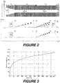
- FIG 2 shows an embodiment with an accumulation unit (11a) between an entrance funnel (10) and separator tunnel (11b).
- the accumulation unit (11a) is designed identical to the mobility separator tunnel (11b) (scan unit), just doubling the separator tunnel (11b) with its segmented diaphragm electrodes for generating a quadrupolar RF field, and doubling the voltage supply units (with voltage dividers) for generating two independent axial DC electric field barriers in series.
- the field profiles for the two operation phases are shown; the accumulation and scan phase (D), and the ion transfer phase (E).
- both rising edges (ramps) of the field profile are linear, which can result in an unfavorable high density of ions with low mobilities near the top of the profile leading to high losses of these ions due to Coulomb repulsion ("space charge effect").
- the high mass ions usually having low mobilities because of their high cross sections, get lost first because they are much less strongly focused by the pseudo-potential within the quadrupolar RF field than low mass ions, showing high mobility due to their lower cross section.
- the effective force corresponding to the pseudo-potential is proportional to z 2 /m, z being the number of elementary charges of the ion, and m their mass.
- High mass ions are only weakly focused, and thus are more sensitive to space charge repulsion, driving the ions radially out of the device.
- severe losses of high mass ions already start with accumulation times above 40 milliseconds.
- the mobility resolution is restricted to only R mob ⁇ 65, because the mobility resolution of a trapping ion mobility spectrometer depends on the scan time t s .
- the scan time t s is defined here as the time needed to scan over a common mobility range from low mobility ( Ko ⁇ 0.5 cm 2 /Vs) to high mobility ( Ko ⁇ 1.0 cm 2 /Vs).
- the dependence of the mobility resolution on the scan time is shown in Figure 3 . Since the mobility resolution R mob also depends on the mobility K itself, the dependence is shown for ions with Ko ⁇ 0.5 cm 2 /Vs.
- the present invention further proposes to decrease the density for low mobility ions near the summit, and to accept a higher density of high mobility ions near the foot of the axial DC electric field barrier.
- This goal can be achieved by a non-constant gradient (slope) of the electric field E(z) at the rising edge of the axial DC electric field barrier.
- a preferred embodiment is given by the profile in part (F) of Figure 4 .
- This form of field ramp decreases the field gradient near the summit, decompressing the high mass ion density, and increases the field gradient near the foot, compressing the low mass ion density.
- FIG. 5 Another embodiment of the invention is shown in part (G) of Figure 5 , showing a piecewise linear increase with three different gradients of the electric field.
- the field gradient between z positions (52) and (53), and between (57) and (58) near the top are flattest, decompressing the ions with low mobility and reducing the space charge repulsion.
- more than just three gradients may be applied.
- the electric field profiles are adjusted with respect to the ion density in the mobility spectrum determined in one or more preceding measurements.
- the gradients of the piecewise linear parts of the rising edge can be varied by two voltage generators delivering each three adjustable voltages V 51 , V 52 and V 54 , and V 56 , V 57 and V 59 , which are applied to diaphragms at corresponding positions on the z axis.
- V 51 and V 52 relative to voltage V 54
- a variety of field profiles for the accumulation unit can be generated.
- the field gradient between positions (52) and (53) can be made as flat as necessary to avoid losses.
- the preceding measurement can also be used to adjust the field profile of the scan unit. As a matter of course, more adjustable voltages may be used at more z positions.
- voltages at all or a large part of the diaphragms along the z -axis may be generated by a series of digital-to-analog converters (DAC). Then, any field profile can be generated, enabling an operation which reacts exactly to any density distribution of ions on the mobility scale.
- DAC digital-to-analog converters
- the accumulation unit of the device must not necessarily be identical in design with the scan unit.
- the ions can be accumulated in an octopole or hexapole RF field, instead of a quadrupolar one.
- Hexapole and octopole fields can take up more ions.
- Segmented diaphragms for generating hexapole or octopole RF fields may be designed similar to the segmented diaphragms (1, 2, 3, 4) used for the scan unit (11b), only with more radial electrode segments. Because it is useless to collect more ions than can be held in the scan unit (11b) with a quadrupolar RF field, the multipole accumulation unit can be made shorter.
- the funnel (10) can be made longer to increase its volume, and an additional voltage supply unit may deliver a switchable repelling DC potential (stopping voltage) to the last diaphragm of the funnel (10).
- An accumulation unit upstream of the entrance funnel can be implemented as a common linear RF ion trap comprising a quadrupole, hexapole or octopole RF rod system.
- Storage devices of this type are well-known to the specialist in the field and need not be further described here.
- a scan mode with a partial slow scan speed can increase the mobility resolution for ions in a smaller range of mobilities.
- a "zoom scan” consists of three phases: a first partial scan with highest scan speed, a second "zoom” phase with a reduced scan speed for highest resolution, and a third phase with fast scan speed to empty the trap.
- the capacity of the accumulation and scan units also can be increased by enlarging the inner diameter of the device.
- a larger ion mobility spectrometer with higher RF voltages may still be acceptable for a mass spectrometer, but the gas flow, increasing with the fourth order of the inner diameter, needs much bigger and more expensive vacuum pumps.
Landscapes
- Chemical & Material Sciences (AREA)
- Analytical Chemistry (AREA)
- Physics & Mathematics (AREA)
- Spectroscopy & Molecular Physics (AREA)
- Chemical Kinetics & Catalysis (AREA)
- Electrochemistry (AREA)
- Health & Medical Sciences (AREA)
- Life Sciences & Earth Sciences (AREA)
- Biochemistry (AREA)
- General Health & Medical Sciences (AREA)
- General Physics & Mathematics (AREA)
- Immunology (AREA)
- Pathology (AREA)
- Other Investigation Or Analysis Of Materials By Electrical Means (AREA)
- Electron Tubes For Measurement (AREA)
Description
- The invention relates to devices and methods for the acquisition of mass spectra of ions separated by their mobility.
- In document
US 7,838,826 B1 (M. A. Park, 2008 ), a relatively small ion mobility spectrometer is presented which is termed "trapped ion mobility spectrometer" (TIMS). The length of the essential mobility separation unit, the separator tunnel, amounts to about five centimeters only, not counting additional entrance and exit funnels. The separation of ions according to their mobilities is based upon a gas flow in the cylindrical separator tunnel which drives the ions from an ion source in an accumulation phase against a counter-acting electric DC field barrier while the ions are radially confined by a quadrupolar RF field. After shutting down the delivery of further ions, a scan phase starts, in which the electric DC field barrier is steadily decreased. Ions are driven in the scan phase by the gas flow over the decreasing electric DC field barrier, thereby releasing, successively, ions from low mobilities to higher and higher mobilities from being trapped by the barrier. The ions can be detected in an ion detector, resulting in a mobility spectrum. -
Figure 1 schematically shows a preferred design and operation of a trapping ion mobility spectrometer as described inUS 7,838,826 B1 . The tube-like separator tunnel (11) between entrance funnel (10) and exit funnel (12) amount to only 48 millimeters in length; the inner diameter amounts to eight millimeters. The ion mobility separator tunnel (11) consists of a series of segmented diaphragms with quadrant electrodes (1), (2), (3), and (4), for generating a quadrupolar RF field. Ions (6) from a source (not shown) are introduced by capillary (8) together with a gas stream (7) into a first vacuum chamber. A repeller plate (9) directs the ions into the funnel (10); the gas flow (14) drives the ions into the separator tunnel (11). In the bottom part ofFigure 1 , electric field profiles E(z) along the z-axis are shown for three phases of operation: In the accumulation phase (A) ions are blown by the gas flow (16) against the rising edge of the electric field profile between z locations (20) and (23). In a trap phase (B) of only one to two milliseconds, the inflow of ions is stopped and ions assume their equilibrium position on the rising edge according to their mobility. The steadily decreasing profile voltage in the scan phase (C) releases ions in the order of increasing ion mobility over the plateau of the electric field between locations (23) and (24) and through the exit funnel towards an ion detector. Particularly, the ions may be measured by a mass spectrometer, e.g. a time-of-flight mass spectrometer, resulting in a two-dimensional mass-mobility spectrum. Unlike many other trials to build small ion mobility spectrometers, the device by M. A. Park has already achieved ion mobility resolutions up to R mob = 250, a very high ion mobility resolution never achieved by conventional mobility spectrometers. - There is still a need for devices and methods operating with highest utility rates (duty cycle) of the ions generated in an ion source of a mass spectrometer, thereby reducing the restriction of the mobility resolution, in particular with an electrospray ion source coupled to liquid chromatography for analyzing complex samples in the field of bottom-up proteomics.
- The invention is defined by a method according to
claim 1. - The utilization rate of ions produced in an ion source, accumulated and subsequently separated in an trapping ion mobility spectrometer known from the prior art is limited by the ratio q = t a/(t a+t s) wherein t a is the ion accumulation time in the trapping ion mobility separator and t s is the scan time of the electric DC field barrier, during which ions cannot be accumulated in the trapping ion mobility separator. The utilization rate is also termed "duty cycle" here. According to the present invention, the duty cycle can be close to 100 percent when no ions get lost in the RF ion trap (accumulation unit) and in the trapping ion mobility separator (scan unit).
- In one embodiment, the ions are radially confined in the trapping ion mobility separator by a quadrupolar RF field. The ions can be accumulated in a RF funnel located between the ion source and the trapping ion mobility separator wherein the field at the exit of the RF funnel is preferably adjusted to the quadrupolar RF field at the entrance of the trapping ion mobility separator. The ions are preferably accumulated in a linear RF trap having a quadrupolar RF field for radially confining the ions. RF fields with higher multipoles, like a hexapolar or octopolar RF fields, can further enhance the ion storage capacity of the linear RF ion trap, but it is more elaborate to couple them with the preferred quadrupolar RF field of the trapping ion mobility separator.
- In another embodiment, steps (b) and (c) are repeated to acquire a series of ion mobility spectra, in particular a time series of ion mobility spectra. The ion density can be determined as a function of ion mobility from one or more preceding ion mobility spectra and then used to adjust the electric field profile of the rising edge of the first electric DC field barrier in order to minimize ion losses in the trapping ion mobility separator during steps (b) and (c). The electric field profile is preferably adjusted such that ions are decompressed where a high ion density is determined or where ions of interest are determined.
- The ions can be axially trapped at the exit of the RF ion trap by applying a repelling DC potential to an exit electrode of the RF ion trap during steps (a) and (c). The accumulated ions are pushed by the gas flow against a rising edge of a second axial electric DC field barrier located in the RF ion trap. During steps (a) and (c), the height of the second DC field barrier is adjusted such that ions are trapped along the rising edge of the second DC field barrier and spatially separated according to ion mobility. In step (b), at least a subset of the accumulated ions is transferred into the trapping ion mobility separator by reversing, turning-off or decreasing the height of the second electric field barrier. The electric field profile of the rising edge of the second electric DC field barrier can also be adjusted to minimize ion losses in the RF ion trap during steps (a) and (c), in particular after determining the ion density as a function of ion mobility from one or more preceding ion mobility spectra.
- In another embodiment, the transferred ions are further analyzed in a mass analyzer being located downstream of the trapping ion mobility separator. The transferred ions are preferably fragmented in a fragmentation cell located downstream of the ion trapping mobility separator wherein the fragments ions are analyzed in a mass analyzer located downstream of the fragmentation cell. Precursor ions can be selected in an additional mass analyzer located between the trapping ion mobility separator and the fragmentation cell and then fragmented in the fragmentation cell.
- A system comprising an ion source, an RF ion trap and a trapping ion mobility : separator is also provided however not claimed. The trapping ion mobility separator comprises an RF field for radially confining ions, an axially acting electric DC field barrier having a rising edge with an increasing electric DC field and a gas flow counter-acting the electric DC field at the rising edge. The RF ion trap (accumulation unit) is located between the ion source and the trapping ion mobility separator and has a first mode of operation for accumulating ions from the ion source and a second mode of operation for transferring ions towards the trapping ion mobility separator.
- The RF ion trap (accumulation unit) is an RF funnel or a linear RF ion trap. The linear RF ion trap is preferably aligned along a common axis with the ion trapping mobility separator wherein both, the linear RF ion trap and the trapping ion mobility separator, comprise a tube for radially confining the gas flow along the common axis. The linear ion trap can be designed as an upstream extension of the trapping ion mobility separator having a length of more than three centimeters, more preferably of more than five centimeters, up to ten centimeters. The linear RF ion trap can be composed of segmented diaphragms with quadrant electrodes as shown in
Figure 1 . The inner diameter of the linear ion trap is preferably adjusted to the inner diameter of the trapping ion mobility separator. Preferably, the radially confining RF fields of the linear RF ion trap and the trapping ion mobility separator are substantially quadrupolar. - The linear RF ion trap can comprise an electric DC field barrier having a rising edge with an increasing axial electric DC field. The slope (axial gradient) of the electric field strength along the rising edge of at least one of the electric DC field barriers is preferably not constant in a substantial portion of the rising edge.
- The system can further comprise at least one mass analyzer located downstream of the trapping ion mobility separator. The mass analyzer can be one of an orthogonal time-of-flight mass analyzer, a quadrupole filter, an RF ion trap, an electrostatic ion trap and an ion cyclotron resonance mass spectrometer and it is located downstream of the ion mobility analyzer. The system can further comprise a fragmentation cell located between the trapping ion mobility analyzer and a mass analyzer. The fragmentation cell can be configured to fragment ions by one of collisional induced dissociation (CID), photon induced dissociation (PID), electron capture dissociation (ECD) and electron transfer dissociation (ETD). An additional mass analyzer can be located between the trapping ion mobility separator and the fragmentation cell for selecting precursor ions. The ion source of the system can, for example, be one of an electrospray ion source (ESI), a chemical ionization ion source (CI), a matrix-assisted laser desorption/ionization ion source (MALDI) and an electron impact ion source (EI).
-
-
Figure 1 schematically illustrates the design and operation of an ion mobility spectrometer according to prior art, as described inUS 7,838,826 B1 (M. A. Park, 2008 ). -
Figure 2 shows an embodiment of a mobility spectrometer according to the present invention, with an elongated tunnel (11), divided into an accumulation unit (11a) and a scan unit (11b), and two voltage supply units (not shown) for the two tunnel units (11a, 11b), contacting the diaphragms at locations (31) and (34). Chains of resistors between the diaphragms in both tunnel units produce two axial electric DC field profiles, shown in the bottom part of the figure. The operation comprises two phases: In the accumulation and scan phase (D), ions from an ion source (not shown) are accumulated on the rising edge of the electric field profile in the accumulation unit (11a) while, at the same time, ions in the scan unit (11b) are scanned by decreasing the voltage supplied to location (34) of the scan unit (11b), thereby releasing ions with higher and higher mobilities through the exit funnel (13) towards the ion detector. In the transfer phase (E), first the voltage of the scan unit (11b) is restored, and then the voltage of the accumulation unit (11a) is switched off to let the ions be driven by the gas flow onto the rising edge of the electric field profile of the scan unit (11b). The transfer is completed after only one millisecond, and the accumulation and scan phase may start again by switching on the voltage at location (31). -
Figure 3 shows the dependence of the mobility resolution R for the device shown inFigure 1 , given for ions of low mobility (Ko ≈ 0.5 cm2/Vs), on the scan time t s. The scan time t s comprises the full scan from low mobility (Ko ≈ 0.5 cm2/Vs) to high mobility (Ko ≈1.0 cm2/Vs). Usually, the general interest is on ions of low mobility because they show the highest variety of folding states. A scan time of 60 milliseconds over the full range of mobilities achieves a mobility resolution of R ≈ 80; a mobility resolution of R ≈ 125 needs a scan time of 360 milliseconds. -
Figure 4 shows two different profiles of the electric field, generating different ion densities near the top of the electric field profile. In the upper part (D), repeated fromFigure 2 , the electric field strength increases linearly along the z-axis of the device, showing equal ion density along the ramp, in case a mixture of ions with uniform mobility distribution is provided. In the bottom profile (F), the electric field increases proportionally to z 2/3. As indicated by the dots, high mass ions near the top of the ramp are uncompressed by the field proportional to z 2/3, whereas low mass ions are compressed at the foot of the ramp. Near the top of the ramp, the space charge is diminished, and losses of high mass ions are considerably reduced. -
Figure 5 again shows two different profiles of the electric field. In the upper part (D), repeated for reasons of comparison fromFigure 2 , the electric field strength increases linearly along the axis z of the device. Below, in part (F), the ramp of the electric field shows, in the accumulation unit as well as in the scan unit, three linear field gradients. In the accumulation profile, the linear field gradients are located between z locations (50) and (51), (51) and (52), and (52) and (53) respectively, the lowest gradient near the top. In the scan profile, the linear field gradients are positioned between z locations (55) and (56), (56) and (57), and (57) and (58) respectively. Near both tops, ion density and space charge are diminished, compared with the profile in part (D) at the top. In the second field profile, a further decompression of ions is achieved by a shorter length L p of the plateau. - The present invention provides an ion mobility spectrometer of the type described in document
US 7,838,826 B1 (M. A. Park, 2008 ), additionally equipped with an upfront RF ion trap operated as an accumulation unit. The accumulation unit operates in parallel with the trapping ion mobility separator, preferably implemented as a separator tunnel. That is, while the trapping ion mobility separator is being used to analyze a first group of ions according to ion mobility, the accumulation unit is simultaneously collecting a second group of ions from an ion source. This second group is then rapidly transferred - in about a millisecond to the trapping ion mobility separator once the analysis of the first group is complete. This allows the accumulation unit to collect ions nearly continuously while the trapping ion mobility separator analyzes ions nearly continuously. In a first preferred embodiment, the accumulation unit is located between an entrance funnel and a separation tunnel. In a second embodiment, the entrance funnel itself can be designed to serve as the accumulation unit. In a third embodiment, the accumulation unit is located upstream of the entrance funnel. - Particularly, in the case of the first embodiment with the accumulation unit located between the entrance funnel and the trapping ion mobility separator, the accumulation unit is preferably designed identical to the trapping ion mobility separator (scan unit), just doubling the scan unit with segmented diaphragm electrodes for generating a quadrupole RF field, and doubling the voltage supply units (with voltage dividers) for generating two independent axial DC electric field barriers. The rising edge of the electric field barrier may not increase as a single linear ramp, but may show a flatter gradient near the top of the barrier, to decompress the density of ions of low mobility. This decompression may be used in both axial DC electric field barriers, in the accumulation barrier and in the scan barrier, to reduce losses of ions. Experience shows that the transfer of ions by the gas flow from the accumulation unit to the scan unit of the device only needs a single millisecond. The delivery of further ions from the ion source need never be stopped. If the accumulation time can be increased to about 300 milliseconds, also a scan time of 300 milliseconds can be used, resulting in a high mobility resolution of R mob ≈ 120. If no ions get lost in the accumulation unit and scan unit, the utilization of ions amounts to 100 percent.
- The accumulation unit must not necessarily be identical with the scan unit of the device. As an example, ions can be accumulated in an octopole or hexapole RF field, instead of a quadrupolar one. Hexapole and octopole RF fields can take up more ions. They can be made shorter than the scan unit, because it is useless to collect more ions than can be held in the scan unit of the device.
- If the entrance funnel (10) of
Figure 1 is used as the accumulation unit, only small design changes need to be made to adapt its size and function to take up sufficient ions for the subsequent mobility analysis. An accumulation unit located upstream of the entrance funnel can be designed as a common RF linear ion trap comprising a quadrupole, hexapole or octopole RF rod system. -
Figure 2 shows an embodiment with an accumulation unit (11a) between an entrance funnel (10) and separator tunnel (11b). The accumulation unit (11a) is designed identical to the mobility separator tunnel (11b) (scan unit), just doubling the separator tunnel (11b) with its segmented diaphragm electrodes for generating a quadrupolar RF field, and doubling the voltage supply units (with voltage dividers) for generating two independent axial DC electric field barriers in series. In the lower part ofFigure 2 , the field profiles for the two operation phases are shown; the accumulation and scan phase (D), and the ion transfer phase (E). - In
Figure 2 , both rising edges (ramps) of the field profile are linear, which can result in an unfavorable high density of ions with low mobilities near the top of the profile leading to high losses of these ions due to Coulomb repulsion ("space charge effect"). With long accumulation times, the high mass ions, usually having low mobilities because of their high cross sections, get lost first because they are much less strongly focused by the pseudo-potential within the quadrupolar RF field than low mass ions, showing high mobility due to their lower cross section. The effective force corresponding to the pseudo-potential is proportional to z 2/m, z being the number of elementary charges of the ion, and m their mass. High mass ions are only weakly focused, and thus are more sensitive to space charge repulsion, driving the ions radially out of the device. With standard high performance electrospray ion sources, severe losses of high mass ions already start with accumulation times above 40 milliseconds. If the accumulation and scan times are restricted to only 40 milliseconds, the mobility resolution is restricted to only R mob ≈ 65, because the mobility resolution of a trapping ion mobility spectrometer depends on the scan time t s. The scan time t s is defined here as the time needed to scan over a common mobility range from low mobility (Ko ≈ 0.5 cm2/Vs) to high mobility (Ko ≈ 1.0 cm2/Vs). The dependence of the mobility resolution on the scan time is shown inFigure 3 . Since the mobility resolution R mob also depends on the mobility K itself, the dependence is shown for ions with Ko ≈ 0.5 cm2/Vs. - To overcome losses of high mass ions, the present invention further proposes to decrease the density for low mobility ions near the summit, and to accept a higher density of high mobility ions near the foot of the axial DC electric field barrier. This goal can be achieved by a non-constant gradient (slope) of the electric field E(z) at the rising edge of the axial DC electric field barrier. A preferred embodiment is given by the profile in part (F) of
Figure 4 . Here, the electric field increases non-linearly according to the function E(z) ∼ zp , with an exponent p = 2/3. This form of field ramp decreases the field gradient near the summit, decompressing the high mass ion density, and increases the field gradient near the foot, compressing the low mass ion density. The value p = 2/3 is only an example; in fact, p may assume any value smaller than 1.0. A favorable range for the exponent p is 0.3 ≤ p ≤ 0.9. If the mixture of ions contains many high mass ions, a value of p = 1/2 may be more favorable; in the extreme, even p = 1/3 may serve the purpose best. - Another embodiment of the invention is shown in part (G) of
Figure 5 , showing a piecewise linear increase with three different gradients of the electric field. The field gradient between z positions (52) and (53), and between (57) and (58) near the top are flattest, decompressing the ions with low mobility and reducing the space charge repulsion. Of course, more than just three gradients may be applied. - In another embodiment, the electric field profiles are adjusted with respect to the ion density in the mobility spectrum determined in one or more preceding measurements. As an example for a variable field profile, the gradients of the piecewise linear parts of the rising edge, as shown in part (G) of
Figure 5 , can be varied by two voltage generators delivering each three adjustable voltages V 51, V 52 and V 54, and V 56, V 57 and V 59, which are applied to diaphragms at corresponding positions on the z axis. By adjusting, for example, the voltages V 51 and V 52 relative to voltage V 54, a variety of field profiles for the accumulation unit can be generated. If a preceding measurement shows a high density of low mobility ions, the field gradient between positions (52) and (53) can be made as flat as necessary to avoid losses. The preceding measurement can also be used to adjust the field profile of the scan unit. As a matter of course, more adjustable voltages may be used at more z positions. - With a more complex device, voltages at all or a large part of the diaphragms along the z-axis may be generated by a series of digital-to-analog converters (DAC). Then, any field profile can be generated, enabling an operation which reacts exactly to any density distribution of ions on the mobility scale.
- For reason of comparison, the upper parts (D) of
Figures 4 and 5 show a field ramp of linear increase, where it is to be seen that the ions of a mixture having a uniform mobility distribution are uniformly distributed along the rising edge. In practice, however, the mobilities of ions are rarely uniformly distributed. - Experience shows that the transfer of ions by the gas flow from the accumulation unit to the scan unit of the device only needs some millisecond or less when the gas has a velocity of about 100 m/s at a pressure of some millibar. The delivery of further ions from the ion source need never be stopped. If the accumulation time can be increased to about 300 milliseconds without major losses of ions, a scan time of 300 milliseconds can be used, resulting in a high mobility resolution of R mob ≈ 120. If no ions get lost in the accumulation unit and scan unit at all, then the duty cycle would be to 100 percent.
- The accumulation unit of the device must not necessarily be identical in design with the scan unit. As an example, the ions can be accumulated in an octopole or hexapole RF field, instead of a quadrupolar one. Hexapole and octopole fields can take up more ions. Segmented diaphragms for generating hexapole or octopole RF fields may be designed similar to the segmented diaphragms (1, 2, 3, 4) used for the scan unit (11b), only with more radial electrode segments. Because it is useless to collect more ions than can be held in the scan unit (11b) with a quadrupolar RF field, the multipole accumulation unit can be made shorter.
- In case an entrance funnel is used as accumulation unit, only small design changes need to be made to the setup shown in
Figure 1 in order to accumulate a sufficient number of ions from the ion source. The funnel (10) can be made longer to increase its volume, and an additional voltage supply unit may deliver a switchable repelling DC potential (stopping voltage) to the last diaphragm of the funnel (10). - An accumulation unit upstream of the entrance funnel can be implemented as a common linear RF ion trap comprising a quadrupole, hexapole or octopole RF rod system. Storage devices of this type are well-known to the specialist in the field and need not be further described here.
- It should be mentioned that the scan need not necessarily be performed by linearly decreasing the voltage for the field profile. In the patent
US 8,766,176 B2 (M. A. Park et al, 2011 ), different scan modes are presented. In particular, a scan mode with a partial slow scan speed can increase the mobility resolution for ions in a smaller range of mobilities. A "zoom scan" consists of three phases: a first partial scan with highest scan speed, a second "zoom" phase with a reduced scan speed for highest resolution, and a third phase with fast scan speed to empty the trap. - It goes without saying that the capacity of the accumulation and scan units also can be increased by enlarging the inner diameter of the device. A larger ion mobility spectrometer with higher RF voltages may still be acceptable for a mass spectrometer, but the gas flow, increasing with the fourth order of the inner diameter, needs much bigger and more expensive vacuum pumps.
Claims (12)
- A method for operating a trapping ion mobility spectrometer, said trapping ion mobility spectrometer comprising an ion source, an RF ion trap and a trapping ion mobility separator, comprising the steps:(a) accumulating ions from the ion source in the RF ion trap;(b) transferring at least a subset of the accumulated ions into the trapping ion mobility separator, in which the transferred ions are radially confined by an RF field and pushed by a gas flow against a rising edge of a first axial electric DC field barrier such that the transferred ions are spatially separated along the rising edge according to ion mobility; and(c) acquiring an ion mobility spectrum of the transferred ions by decreasing the height of the first electric DC field barrier while ions from the ion source are further accumulated in the RF ion trap,wherein, during steps (a) and (c), the accumulated ions are pushed by the gas flow in the axial direction against a rising edge of a second electric DC field barrier in the RF ion trap and
wherein the height of the second DC field barrier is adjusted such that ions are trapped along the rising edge of the second DC field barrier and spatially separated according to ion mobility. - The method according to claim 1, wherein the ions are radially confined by a quadrupolar RF field in the trapping ion mobility separator.
- The method according to claim 2, wherein the accumulated ions are radially confined in the RF ion trap by one of quadrupolar, hexapolar and octopolar RF field.
- The method according to one of claims 1 to 3, wherein steps (b) and (c) are repeated to acquire a series of ion mobility spectra.
- The method according to claim 4, wherein the ion density is determined as a function of ion mobility from one or more preceding ion mobility spectra and the electric field profile of the rising edge of the first electric DC field barrier is adjusted by a non-constant electric field gradient to minimize ion losses in the trapping ion mobility separator during steps (b) and (c).
- The method according to claim 1, wherein, in step (b), ions are transferred into the trapping ion mobility separator by reversing, turning-off or decreasing the height of the second electric field barrier.
- The method according to claim 1 to 6, wherein the ion density is determined as a function of ion mobility from one or more preceding ion mobility spectra and the electric field profile of the rising edge of the second electric DC field barrier is adjusted by a non-constant electric field gradient to minimize ion losses in the RF ion trap during steps (a) and (c).
- The method according to one of claims 1 to 7, wherein the delivery of ions from the ion source to the RF ion trap is never stopped.
- The method according to claim 1 or 2, wherein the ions are accumulated in a linear RF trap.
- The method according to one of claims 1 to 9, wherein the transferred ions are further analyzed in a mass spectrometer located downstream of the trapping ion mobility separator.
- The method according to one of claims 1 to 9, wherein the transferred ions are fragmented in a fragmentation cell located downstream of the trapping ion mobility separator and the fragment ions are analyzed in a mass analyzer located downstream of the fragmentation cell.
- The method according to claim 11, wherein precursor ions are selected in an additional mass analyzer located between the trapping ion mobility separator and the fragmentation cell and then fragmented in the fragmentation cell.
Priority Applications (1)
| Application Number | Priority Date | Filing Date | Title |
|---|---|---|---|
| EP20184934.6A EP3783638A1 (en) | 2015-02-05 | 2016-01-27 | Trapping ion mobility spectrometer with parallel accumulation |
Applications Claiming Priority (1)
| Application Number | Priority Date | Filing Date | Title |
|---|---|---|---|
| US14/614,456 US9683964B2 (en) | 2015-02-05 | 2015-02-05 | Trapping ion mobility spectrometer with parallel accumulation |
Related Child Applications (2)
| Application Number | Title | Priority Date | Filing Date |
|---|---|---|---|
| EP20184934.6A Division-Into EP3783638A1 (en) | 2015-02-05 | 2016-01-27 | Trapping ion mobility spectrometer with parallel accumulation |
| EP20184934.6A Division EP3783638A1 (en) | 2015-02-05 | 2016-01-27 | Trapping ion mobility spectrometer with parallel accumulation |
Publications (2)
| Publication Number | Publication Date |
|---|---|
| EP3054473A1 EP3054473A1 (en) | 2016-08-10 |
| EP3054473B1 true EP3054473B1 (en) | 2020-10-21 |
Family
ID=55236302
Family Applications (2)
| Application Number | Title | Priority Date | Filing Date |
|---|---|---|---|
| EP20184934.6A Pending EP3783638A1 (en) | 2015-02-05 | 2016-01-27 | Trapping ion mobility spectrometer with parallel accumulation |
| EP16152865.8A Active EP3054473B1 (en) | 2015-02-05 | 2016-01-27 | Trapping ion mobility spectrometer with parallel accumulation |
Family Applications Before (1)
| Application Number | Title | Priority Date | Filing Date |
|---|---|---|---|
| EP20184934.6A Pending EP3783638A1 (en) | 2015-02-05 | 2016-01-27 | Trapping ion mobility spectrometer with parallel accumulation |
Country Status (3)
| Country | Link |
|---|---|
| US (1) | US9683964B2 (en) |
| EP (2) | EP3783638A1 (en) |
| CN (1) | CN105869983B (en) |
Cited By (2)
| Publication number | Priority date | Publication date | Assignee | Title |
|---|---|---|---|---|
| EP3736566B1 (en) * | 2018-02-23 | 2022-11-09 | Bruker Scientific LLC | Tandem ion mobility spectrometer |
| WO2025133851A1 (en) | 2023-12-18 | 2025-06-26 | Ecole Polytechnique Federale De Lausanne (Epfl) | Device and method for ion mobility and charge separation, and for ion filtering |
Families Citing this family (54)
| Publication number | Priority date | Publication date | Assignee | Title |
|---|---|---|---|---|
| US10861687B2 (en) * | 2015-04-23 | 2020-12-08 | Micromass Uk Limited | Separating ions in an ion trap |
| US9546980B1 (en) * | 2015-11-03 | 2017-01-17 | Bruker Daltonik Gmbh | Spatial zoom mode for accumulative trapped ion mobility spectrometry |
| US9891194B2 (en) * | 2015-11-03 | 2018-02-13 | Bruker Daltonik Gmbh | Acquisition of fragment ion mass spectra of ions separated by their mobility |
| US9984864B2 (en) * | 2015-11-03 | 2018-05-29 | Bruker Daltonik Gmbh | Spatial zoom mode for accumulative trapped ion mobility spectrometry |
| US9978578B2 (en) * | 2016-02-03 | 2018-05-22 | Fasmatech Science & Technology Ltd. | Segmented linear ion trap for enhanced ion activation and storage |
| GB201608653D0 (en) | 2016-05-17 | 2016-06-29 | Micromass Ltd | Ion mobility seperator |
| DE102017111067B4 (en) | 2016-06-02 | 2021-09-23 | Bruker Daltonics GmbH & Co. KG | Isomer analysis in TIMS-Q-q-TOF mass spectrometers |
| US10458944B2 (en) * | 2016-06-03 | 2019-10-29 | Bruker Daltonik Gmbh | Trapped ion mobility spectrometer with high ion storage capacity |
| CN108091537B (en) * | 2016-11-21 | 2020-04-07 | 中国科学院大连化学物理研究所 | Step field ion migration tube |
| US10241079B2 (en) | 2017-05-24 | 2019-03-26 | Bruker Daltonik Gmbh | Mass spectrometer with tandem ion mobility analyzers |
| CN109003877B (en) * | 2017-06-06 | 2020-10-16 | 岛津分析技术研发(上海)有限公司 | Ion mobility analysis device and analysis method applied to same |
| JP7158642B2 (en) * | 2018-01-16 | 2022-10-24 | 国立大学法人山梨大学 | Mass spectrometer and mass spectrometry system |
| WO2019222274A1 (en) | 2018-05-14 | 2019-11-21 | MOBILion Systems, Inc. | Coupling of ion mobility spectrometer with mass spectrometer |
| EP3578966B1 (en) * | 2018-06-04 | 2025-11-05 | Bruker Scientific LLC | Separation of ions according to ion mobility with enhanced resolving power for mass spectrometric analysis |
| EP4376051A3 (en) * | 2018-06-04 | 2024-09-25 | The Trustees of Indiana University | Charge detection mass spectrometry with real time analysis and signal optimization |
| US11029282B2 (en) | 2018-08-24 | 2021-06-08 | Analytical Detection LLC | Liquid phase ion mobility spectrometer |
| DE102018124203B4 (en) * | 2018-10-01 | 2022-05-25 | Bruker Daltonics GmbH & Co. KG | Determination of the reduced ion mobility of an ion species by stored ion mobility spectrometry (TIMS) |
| US10507980B1 (en) | 2019-02-22 | 2019-12-17 | Planiform Conveyors Inc. | Garment conveyor transport clip with single hanger selection |
| US12431219B2 (en) | 2019-04-15 | 2025-09-30 | Bruker Daltonics GmbH & Co. KG | Methods for determining isomeric amino acid residues of proteins and peptides |
| GB2587249B (en) * | 2019-04-15 | 2023-11-08 | Bruker Daltonics Gmbh & Co Kg | A method for controlling the mass filter in a hybrid IMS/MS system |
| AU2020280042B2 (en) | 2019-05-21 | 2026-03-12 | MOBILion Systems, Inc. | Voltage control for ion mobility separation |
| GB2586321B (en) | 2019-05-31 | 2023-12-13 | Bruker Daltonics Gmbh & Co Kg | Hybrid mass spectrometric system |
| ES3043907T3 (en) | 2019-05-31 | 2025-11-26 | Bruker Scient Llc | Mass spectrometric system with ion mobility analyzer at elevated pressure |
| US11380531B2 (en) | 2019-11-08 | 2022-07-05 | Thermo Finnigan Llc | Methods and apparatus for high speed mass spectrometry |
| WO2021102406A1 (en) | 2019-11-22 | 2021-05-27 | MOBILion Systems, Inc. | Mobility based filtering of ions |
| US11114293B2 (en) | 2019-12-11 | 2021-09-07 | Thermo Finnigan Llc | Space-time buffer for ion processing pipelines |
| WO2021207235A1 (en) | 2020-04-06 | 2021-10-14 | MOBILion Systems, Inc. | Systems and methods for two-dimensional mobility based filtering of ions |
| US12163920B2 (en) | 2020-04-06 | 2024-12-10 | MOBILion Systems, Inc. | Systems and methods for two-dimensional mobility based filtering of ions |
| DE102020111240B3 (en) | 2020-04-24 | 2021-10-28 | Bruker Daltonics GmbH & Co. KG | Processing of spatially resolved, ion-spectrometric measurement signal data for the determination of molecular content indexes in flat samples |
| CA3178943A1 (en) | 2020-05-22 | 2021-11-25 | MOBILion Systems, Inc. | Methods and apparatus for trapping and accumulation of ions |
| EP3916755A1 (en) | 2020-05-26 | 2021-12-01 | Thermo Finnigan LLC | Methods and apparatus for high speed mass spectrometry |
| EP4161683A4 (en) | 2020-06-05 | 2024-07-03 | Mobilion Systems, Inc. | APPARATUS AND METHOD FOR ION MANIPULATION WITH IMPROVED DUTY CYCLE |
| US20220057363A1 (en) | 2020-08-20 | 2022-02-24 | Bruker Daltonik Gmbh | Ion mobility separation system with rotating field confinement |
| US11600480B2 (en) | 2020-09-22 | 2023-03-07 | Thermo Finnigan Llc | Methods and apparatus for ion transfer by ion bunching |
| US12620567B2 (en) | 2020-12-31 | 2026-05-05 | MOBILion Systems, Inc. | Apparatus for ion manipulation having curved turn regions |
| US12163919B2 (en) | 2021-03-22 | 2024-12-10 | Bruker Scientific Llc | Laterally-extended trapped ion mobility spectrometer |
| CN115223844B (en) * | 2021-04-21 | 2025-10-14 | 株式会社岛津制作所 | Ion mobility analyzer |
| US20230417704A1 (en) * | 2021-04-21 | 2023-12-28 | Shimadzu Corporation | Ion mobility analysis apparatus |
| DE102021128848B4 (en) | 2021-11-05 | 2025-08-07 | Bruker Daltonics GmbH & Co. KG | Device for desorbing scanning of analyte material on a sample carrier |
| US20240222106A1 (en) * | 2022-12-29 | 2024-07-04 | Thermo Finnigan Llc | Apparatus and Method for Ion Separation |
| DE102023104393A1 (en) | 2023-02-23 | 2024-08-29 | Bruker Daltonics GmbH & Co. KG | Method and device for spectrometric analysis |
| GB2631594B (en) | 2023-06-28 | 2025-08-06 | Bruker Daltonics Gmbh & Co Kg | Differential trapped ion mobility separator |
| GB2633176A (en) | 2023-06-28 | 2025-03-05 | Bruker Daltonics Gmbh & Co Kg | Differential trapped ion mobility filter |
| CN121970144A (en) | 2023-08-24 | 2026-05-01 | 生物诊断系统公司 | System and method for targeted analysis of diagonal series acquired by the dia-PASEF acquisition method |
| DE102024122630A1 (en) | 2023-09-01 | 2025-03-06 | Bruker Daltonics GmbH & Co. KG | DEVICE AND METHOD FOR TRANSFERRING GASEOUS IONIC SAMPLE MATERIAL FOR SUBSEQUENT ANALYSIS |
| WO2025131862A1 (en) | 2023-12-21 | 2025-06-26 | Bruker Switzerland Ag | Tims with synchronized mobility filtering and analysis |
| EP4621402A1 (en) | 2024-03-19 | 2025-09-24 | Bruker Switzerland AG | Differential mobility spectrometer |
| WO2025247797A1 (en) | 2024-05-29 | 2025-12-04 | Bruker Switzerland Ag | Methods and tools for the determination of native structural information of biomolecules using hypenating mass spectroscopy |
| EP4657070A1 (en) | 2024-05-29 | 2025-12-03 | Thermo Finnigan LLC | Methods for ms2 quantitation of isobaric labeled compounds |
| WO2025247796A1 (en) | 2024-05-29 | 2025-12-04 | Bruker Daltonics GmbH & Co. KG | Methods for collision cross-section prediction and ion mobility tandem ms analytical methods using such methods |
| WO2025247635A1 (en) | 2024-05-29 | 2025-12-04 | Bruker Daltonics GmbH & Co. KG | Method and device for combined ion mobility and tandem mass spectroscopy analysis |
| WO2025247636A1 (en) | 2024-05-29 | 2025-12-04 | Bruker Daltonics GmbH & Co. KG | Method and device for data dependent combined ion mobility and mass spectroscopy analysis |
| WO2025247634A1 (en) | 2024-05-31 | 2025-12-04 | Bruker Daltonics GmbH & Co. KG | Ion mobility resolved isotope pattern analysis |
| WO2026057680A1 (en) | 2024-09-16 | 2026-03-19 | Bruker Switzerland Ag | Tims with synchronized mobility and quadrupole filtering |
Citations (3)
| Publication number | Priority date | Publication date | Assignee | Title |
|---|---|---|---|---|
| US20030213900A1 (en) * | 2002-05-17 | 2003-11-20 | Hoyes John Brian | Mass spectrometer |
| WO2009093045A2 (en) * | 2008-01-24 | 2009-07-30 | Micromass Uk Limited | Ion mobility spectrometer |
| WO2014174260A1 (en) * | 2013-04-24 | 2014-10-30 | Micromass Uk Limited | Improved ion mobility spectrometer |
Family Cites Families (9)
| Publication number | Priority date | Publication date | Assignee | Title |
|---|---|---|---|---|
| US3986111A (en) * | 1974-12-24 | 1976-10-12 | The United States Of America As Represented By The Secretary Of The Navy | Inverted voltage Gerdien Condenser |
| GB0313016D0 (en) * | 2003-06-06 | 2003-07-09 | Ms Horizons Ltd | Ion extraction |
| GB0522933D0 (en) * | 2005-11-10 | 2005-12-21 | Micromass Ltd | Mass spectrometer |
| US7888635B2 (en) * | 2008-05-30 | 2011-02-15 | Battelle Memorial Institute | Ion funnel ion trap and process |
| GB0810599D0 (en) * | 2008-06-10 | 2008-07-16 | Micromass Ltd | Mass spectrometer |
| US7838826B1 (en) | 2008-08-07 | 2010-11-23 | Bruker Daltonics, Inc. | Apparatus and method for parallel flow ion mobility spectrometry combined with mass spectrometry |
| US8766176B2 (en) | 2011-04-26 | 2014-07-01 | Bruker Daltonics, Inc. | Spectrum acquisition modes for ion mobility spectrometers using trapped ions |
| US8941055B2 (en) * | 2011-04-26 | 2015-01-27 | Bruker Daltonik Gmbh | Selective ion mobility filter |
| WO2014140579A1 (en) * | 2013-03-13 | 2014-09-18 | Micromass Uk Limited | Coaxial ion guide |
-
2015
- 2015-02-05 US US14/614,456 patent/US9683964B2/en active Active
-
2016
- 2016-01-27 EP EP20184934.6A patent/EP3783638A1/en active Pending
- 2016-01-27 EP EP16152865.8A patent/EP3054473B1/en active Active
- 2016-02-05 CN CN201610082658.0A patent/CN105869983B/en active Active
Patent Citations (3)
| Publication number | Priority date | Publication date | Assignee | Title |
|---|---|---|---|---|
| US20030213900A1 (en) * | 2002-05-17 | 2003-11-20 | Hoyes John Brian | Mass spectrometer |
| WO2009093045A2 (en) * | 2008-01-24 | 2009-07-30 | Micromass Uk Limited | Ion mobility spectrometer |
| WO2014174260A1 (en) * | 2013-04-24 | 2014-10-30 | Micromass Uk Limited | Improved ion mobility spectrometer |
Cited By (2)
| Publication number | Priority date | Publication date | Assignee | Title |
|---|---|---|---|---|
| EP3736566B1 (en) * | 2018-02-23 | 2022-11-09 | Bruker Scientific LLC | Tandem ion mobility spectrometer |
| WO2025133851A1 (en) | 2023-12-18 | 2025-06-26 | Ecole Polytechnique Federale De Lausanne (Epfl) | Device and method for ion mobility and charge separation, and for ion filtering |
Also Published As
| Publication number | Publication date |
|---|---|
| US20160231275A1 (en) | 2016-08-11 |
| CN105869983B (en) | 2018-04-10 |
| EP3783638A1 (en) | 2021-02-24 |
| CN105869983A (en) | 2016-08-17 |
| US9683964B2 (en) | 2017-06-20 |
| EP3054473A1 (en) | 2016-08-10 |
Similar Documents
| Publication | Publication Date | Title |
|---|---|---|
| US9683964B2 (en) | Trapping ion mobility spectrometer with parallel accumulation | |
| US9304106B1 (en) | High duty cycle trapping ion mobility spectrometer | |
| CN104126116B (en) | Apparatus and method for ion mobility spectrometry | |
| US9984864B2 (en) | Spatial zoom mode for accumulative trapped ion mobility spectrometry | |
| CN110186990B (en) | Tandem ion mobility spectrometer | |
| CN107464736B (en) | Trapped ion mobility spectrometer with high ion storage capacity | |
| EP3739616B1 (en) | Triple quadrupole mass spectrometry coupled to trapped ion mobility separation | |
| JP5860958B2 (en) | Target analysis for tandem mass spectrometry | |
| US6852971B2 (en) | Electric charge adjusting method, device therefor, and mass spectrometer | |
| US9546980B1 (en) | Spatial zoom mode for accumulative trapped ion mobility spectrometry | |
| US10510525B2 (en) | Ion beam mass pre-separator | |
| GB2564749A (en) | Mass spectrometer with tandem ion mobility analyzers | |
| US9123517B2 (en) | Ion guide with different order multipolar field order distributions across like segments | |
| US11598749B2 (en) | Mass spectrometric system with ion mobility analyzer at elevated pressure | |
| EP0902963A1 (en) | Axial ejection in a multipole mass spectrometer | |
| CN115201312B (en) | Ion mobility spectrometry | |
| US20250218756A1 (en) | Trapped ion mobility separator with a moving electric field barrier | |
| US20250174449A1 (en) | MSn MASS SPECTROMETRY SYSTEM AND RELATED METHODS |
Legal Events
| Date | Code | Title | Description |
|---|---|---|---|
| PUAI | Public reference made under article 153(3) epc to a published international application that has entered the european phase |
Free format text: ORIGINAL CODE: 0009012 |
|
| 17P | Request for examination filed |
Effective date: 20160128 |
|
| AK | Designated contracting states |
Kind code of ref document: A1 Designated state(s): AL AT BE BG CH CY CZ DE DK EE ES FI FR GB GR HR HU IE IS IT LI LT LU LV MC MK MT NL NO PL PT RO RS SE SI SK SM TR |
|
| AX | Request for extension of the european patent |
Extension state: BA ME |
|
| 17Q | First examination report despatched |
Effective date: 20160829 |
|
| STAA | Information on the status of an ep patent application or granted ep patent |
Free format text: STATUS: EXAMINATION IS IN PROGRESS |
|
| GRAP | Despatch of communication of intention to grant a patent |
Free format text: ORIGINAL CODE: EPIDOSNIGR1 |
|
| STAA | Information on the status of an ep patent application or granted ep patent |
Free format text: STATUS: GRANT OF PATENT IS INTENDED |
|
| INTG | Intention to grant announced |
Effective date: 20200608 |
|
| GRAS | Grant fee paid |
Free format text: ORIGINAL CODE: EPIDOSNIGR3 |
|
| GRAA | (expected) grant |
Free format text: ORIGINAL CODE: 0009210 |
|
| STAA | Information on the status of an ep patent application or granted ep patent |
Free format text: STATUS: THE PATENT HAS BEEN GRANTED |
|
| AK | Designated contracting states |
Kind code of ref document: B1 Designated state(s): AL AT BE BG CH CY CZ DE DK EE ES FI FR GB GR HR HU IE IS IT LI LT LU LV MC MK MT NL NO PL PT RO RS SE SI SK SM TR |
|
| REG | Reference to a national code |
Ref country code: GB Ref legal event code: FG4D |
|
| REG | Reference to a national code |
Ref country code: CH Ref legal event code: EP |
|
| REG | Reference to a national code |
Ref country code: IE Ref legal event code: FG4D |
|
| REG | Reference to a national code |
Ref country code: DE Ref legal event code: R096 Ref document number: 602016046093 Country of ref document: DE |
|
| REG | Reference to a national code |
Ref country code: AT Ref legal event code: REF Ref document number: 1326706 Country of ref document: AT Kind code of ref document: T Effective date: 20201115 |
|
| REG | Reference to a national code |
Ref country code: AT Ref legal event code: MK05 Ref document number: 1326706 Country of ref document: AT Kind code of ref document: T Effective date: 20201021 |
|
| REG | Reference to a national code |
Ref country code: NL Ref legal event code: MP Effective date: 20201021 |
|
| PG25 | Lapsed in a contracting state [announced via postgrant information from national office to epo] |
Ref country code: NO Free format text: LAPSE BECAUSE OF FAILURE TO SUBMIT A TRANSLATION OF THE DESCRIPTION OR TO PAY THE FEE WITHIN THE PRESCRIBED TIME-LIMIT Effective date: 20210121 Ref country code: NL Free format text: LAPSE BECAUSE OF FAILURE TO SUBMIT A TRANSLATION OF THE DESCRIPTION OR TO PAY THE FEE WITHIN THE PRESCRIBED TIME-LIMIT Effective date: 20201021 Ref country code: PT Free format text: LAPSE BECAUSE OF FAILURE TO SUBMIT A TRANSLATION OF THE DESCRIPTION OR TO PAY THE FEE WITHIN THE PRESCRIBED TIME-LIMIT Effective date: 20210222 Ref country code: RS Free format text: LAPSE BECAUSE OF FAILURE TO SUBMIT A TRANSLATION OF THE DESCRIPTION OR TO PAY THE FEE WITHIN THE PRESCRIBED TIME-LIMIT Effective date: 20201021 Ref country code: FI Free format text: LAPSE BECAUSE OF FAILURE TO SUBMIT A TRANSLATION OF THE DESCRIPTION OR TO PAY THE FEE WITHIN THE PRESCRIBED TIME-LIMIT Effective date: 20201021 Ref country code: GR Free format text: LAPSE BECAUSE OF FAILURE TO SUBMIT A TRANSLATION OF THE DESCRIPTION OR TO PAY THE FEE WITHIN THE PRESCRIBED TIME-LIMIT Effective date: 20210122 |
|
| REG | Reference to a national code |
Ref country code: LT Ref legal event code: MG4D |
|
| PG25 | Lapsed in a contracting state [announced via postgrant information from national office to epo] |
Ref country code: AT Free format text: LAPSE BECAUSE OF FAILURE TO SUBMIT A TRANSLATION OF THE DESCRIPTION OR TO PAY THE FEE WITHIN THE PRESCRIBED TIME-LIMIT Effective date: 20201021 Ref country code: ES Free format text: LAPSE BECAUSE OF FAILURE TO SUBMIT A TRANSLATION OF THE DESCRIPTION OR TO PAY THE FEE WITHIN THE PRESCRIBED TIME-LIMIT Effective date: 20201021 Ref country code: BG Free format text: LAPSE BECAUSE OF FAILURE TO SUBMIT A TRANSLATION OF THE DESCRIPTION OR TO PAY THE FEE WITHIN THE PRESCRIBED TIME-LIMIT Effective date: 20210121 Ref country code: SE Free format text: LAPSE BECAUSE OF FAILURE TO SUBMIT A TRANSLATION OF THE DESCRIPTION OR TO PAY THE FEE WITHIN THE PRESCRIBED TIME-LIMIT Effective date: 20201021 Ref country code: IS Free format text: LAPSE BECAUSE OF FAILURE TO SUBMIT A TRANSLATION OF THE DESCRIPTION OR TO PAY THE FEE WITHIN THE PRESCRIBED TIME-LIMIT Effective date: 20210221 Ref country code: LV Free format text: LAPSE BECAUSE OF FAILURE TO SUBMIT A TRANSLATION OF THE DESCRIPTION OR TO PAY THE FEE WITHIN THE PRESCRIBED TIME-LIMIT Effective date: 20201021 Ref country code: PL Free format text: LAPSE BECAUSE OF FAILURE TO SUBMIT A TRANSLATION OF THE DESCRIPTION OR TO PAY THE FEE WITHIN THE PRESCRIBED TIME-LIMIT Effective date: 20201021 |
|
| PG25 | Lapsed in a contracting state [announced via postgrant information from national office to epo] |
Ref country code: HR Free format text: LAPSE BECAUSE OF FAILURE TO SUBMIT A TRANSLATION OF THE DESCRIPTION OR TO PAY THE FEE WITHIN THE PRESCRIBED TIME-LIMIT Effective date: 20201021 |
|
| REG | Reference to a national code |
Ref country code: DE Ref legal event code: R097 Ref document number: 602016046093 Country of ref document: DE |
|
| PG25 | Lapsed in a contracting state [announced via postgrant information from national office to epo] |
Ref country code: SK Free format text: LAPSE BECAUSE OF FAILURE TO SUBMIT A TRANSLATION OF THE DESCRIPTION OR TO PAY THE FEE WITHIN THE PRESCRIBED TIME-LIMIT Effective date: 20201021 Ref country code: RO Free format text: LAPSE BECAUSE OF FAILURE TO SUBMIT A TRANSLATION OF THE DESCRIPTION OR TO PAY THE FEE WITHIN THE PRESCRIBED TIME-LIMIT Effective date: 20201021 Ref country code: EE Free format text: LAPSE BECAUSE OF FAILURE TO SUBMIT A TRANSLATION OF THE DESCRIPTION OR TO PAY THE FEE WITHIN THE PRESCRIBED TIME-LIMIT Effective date: 20201021 Ref country code: CZ Free format text: LAPSE BECAUSE OF FAILURE TO SUBMIT A TRANSLATION OF THE DESCRIPTION OR TO PAY THE FEE WITHIN THE PRESCRIBED TIME-LIMIT Effective date: 20201021 Ref country code: SM Free format text: LAPSE BECAUSE OF FAILURE TO SUBMIT A TRANSLATION OF THE DESCRIPTION OR TO PAY THE FEE WITHIN THE PRESCRIBED TIME-LIMIT Effective date: 20201021 Ref country code: LT Free format text: LAPSE BECAUSE OF FAILURE TO SUBMIT A TRANSLATION OF THE DESCRIPTION OR TO PAY THE FEE WITHIN THE PRESCRIBED TIME-LIMIT Effective date: 20201021 |
|
| PLBE | No opposition filed within time limit |
Free format text: ORIGINAL CODE: 0009261 |
|
| STAA | Information on the status of an ep patent application or granted ep patent |
Free format text: STATUS: NO OPPOSITION FILED WITHIN TIME LIMIT |
|
| PG25 | Lapsed in a contracting state [announced via postgrant information from national office to epo] |
Ref country code: DK Free format text: LAPSE BECAUSE OF FAILURE TO SUBMIT A TRANSLATION OF THE DESCRIPTION OR TO PAY THE FEE WITHIN THE PRESCRIBED TIME-LIMIT Effective date: 20201021 Ref country code: MC Free format text: LAPSE BECAUSE OF FAILURE TO SUBMIT A TRANSLATION OF THE DESCRIPTION OR TO PAY THE FEE WITHIN THE PRESCRIBED TIME-LIMIT Effective date: 20201021 |
|
| REG | Reference to a national code |
Ref country code: CH Ref legal event code: PL |
|
| 26N | No opposition filed |
Effective date: 20210722 |
|
| PG25 | Lapsed in a contracting state [announced via postgrant information from national office to epo] |
Ref country code: LU Free format text: LAPSE BECAUSE OF NON-PAYMENT OF DUE FEES Effective date: 20210127 |
|
| REG | Reference to a national code |
Ref country code: BE Ref legal event code: MM Effective date: 20210131 |
|
| REG | Reference to a national code |
Ref country code: GB Ref legal event code: 732E Free format text: REGISTERED BETWEEN 20210923 AND 20210929 |
|
| REG | Reference to a national code |
Ref country code: DE Ref legal event code: R081 Ref document number: 602016046093 Country of ref document: DE Owner name: BRUKER DALTONICS GMBH & CO. KG, DE Free format text: FORMER OWNER: BRUKER DALTONIK GMBH, 28359 BREMEN, DE |
|
| PG25 | Lapsed in a contracting state [announced via postgrant information from national office to epo] |
Ref country code: IT Free format text: LAPSE BECAUSE OF FAILURE TO SUBMIT A TRANSLATION OF THE DESCRIPTION OR TO PAY THE FEE WITHIN THE PRESCRIBED TIME-LIMIT Effective date: 20201021 Ref country code: AL Free format text: LAPSE BECAUSE OF FAILURE TO SUBMIT A TRANSLATION OF THE DESCRIPTION OR TO PAY THE FEE WITHIN THE PRESCRIBED TIME-LIMIT Effective date: 20201021 Ref country code: FR Free format text: LAPSE BECAUSE OF NON-PAYMENT OF DUE FEES Effective date: 20210131 |
|
| PG25 | Lapsed in a contracting state [announced via postgrant information from national office to epo] |
Ref country code: SI Free format text: LAPSE BECAUSE OF FAILURE TO SUBMIT A TRANSLATION OF THE DESCRIPTION OR TO PAY THE FEE WITHIN THE PRESCRIBED TIME-LIMIT Effective date: 20201021 Ref country code: CH Free format text: LAPSE BECAUSE OF NON-PAYMENT OF DUE FEES Effective date: 20210131 Ref country code: LI Free format text: LAPSE BECAUSE OF NON-PAYMENT OF DUE FEES Effective date: 20210131 |
|
| PG25 | Lapsed in a contracting state [announced via postgrant information from national office to epo] |
Ref country code: IS Free format text: LAPSE BECAUSE OF FAILURE TO SUBMIT A TRANSLATION OF THE DESCRIPTION OR TO PAY THE FEE WITHIN THE PRESCRIBED TIME-LIMIT Effective date: 20210221 |
|
| PG25 | Lapsed in a contracting state [announced via postgrant information from national office to epo] |
Ref country code: BE Free format text: LAPSE BECAUSE OF NON-PAYMENT OF DUE FEES Effective date: 20210131 |
|
| PG25 | Lapsed in a contracting state [announced via postgrant information from national office to epo] |
Ref country code: HU Free format text: LAPSE BECAUSE OF FAILURE TO SUBMIT A TRANSLATION OF THE DESCRIPTION OR TO PAY THE FEE WITHIN THE PRESCRIBED TIME-LIMIT; INVALID AB INITIO Effective date: 20160127 |
|
| PG25 | Lapsed in a contracting state [announced via postgrant information from national office to epo] |
Ref country code: CY Free format text: LAPSE BECAUSE OF FAILURE TO SUBMIT A TRANSLATION OF THE DESCRIPTION OR TO PAY THE FEE WITHIN THE PRESCRIBED TIME-LIMIT Effective date: 20201021 |
|
| P01 | Opt-out of the competence of the unified patent court (upc) registered |
Effective date: 20231221 |
|
| PG25 | Lapsed in a contracting state [announced via postgrant information from national office to epo] |
Ref country code: MK Free format text: LAPSE BECAUSE OF FAILURE TO SUBMIT A TRANSLATION OF THE DESCRIPTION OR TO PAY THE FEE WITHIN THE PRESCRIBED TIME-LIMIT Effective date: 20201021 |
|
| PG25 | Lapsed in a contracting state [announced via postgrant information from national office to epo] |
Ref country code: MT Free format text: LAPSE BECAUSE OF FAILURE TO SUBMIT A TRANSLATION OF THE DESCRIPTION OR TO PAY THE FEE WITHIN THE PRESCRIBED TIME-LIMIT Effective date: 20201021 |
|
| PG25 | Lapsed in a contracting state [announced via postgrant information from national office to epo] |
Ref country code: TR Free format text: LAPSE BECAUSE OF FAILURE TO SUBMIT A TRANSLATION OF THE DESCRIPTION OR TO PAY THE FEE WITHIN THE PRESCRIBED TIME-LIMIT Effective date: 20201021 |
|
| PGFP | Annual fee paid to national office [announced via postgrant information from national office to epo] |
Ref country code: GB Payment date: 20260123 Year of fee payment: 11 |
|
| PGFP | Annual fee paid to national office [announced via postgrant information from national office to epo] |
Ref country code: DE Payment date: 20260121 Year of fee payment: 11 Ref country code: IE Payment date: 20260122 Year of fee payment: 11 |