EP3054294A1 - Column contained in container and column container - Google Patents
Column contained in container and column container Download PDFInfo
- Publication number
- EP3054294A1 EP3054294A1 EP14849999.9A EP14849999A EP3054294A1 EP 3054294 A1 EP3054294 A1 EP 3054294A1 EP 14849999 A EP14849999 A EP 14849999A EP 3054294 A1 EP3054294 A1 EP 3054294A1
- Authority
- EP
- European Patent Office
- Prior art keywords
- container body
- cover
- column
- container
- chromatography column
- Prior art date
- Legal status (The legal status is an assumption and is not a legal conclusion. Google has not performed a legal analysis and makes no representation as to the accuracy of the status listed.)
- Granted
Links
Images



Classifications
-
- G—PHYSICS
- G01—MEASURING; TESTING
- G01N—INVESTIGATING OR ANALYSING MATERIALS BY DETERMINING THEIR CHEMICAL OR PHYSICAL PROPERTIES
- G01N30/00—Investigating or analysing materials by separation into components using adsorption, absorption or similar phenomena or using ion-exchange, e.g. chromatography or field flow fractionation
- G01N30/02—Column chromatography
- G01N30/60—Construction of the column
- G01N30/6047—Construction of the column with supporting means; Holders
-
- B—PERFORMING OPERATIONS; TRANSPORTING
- B65—CONVEYING; PACKING; STORING; HANDLING THIN OR FILAMENTARY MATERIAL
- B65D—CONTAINERS FOR STORAGE OR TRANSPORT OF ARTICLES OR MATERIALS, e.g. BAGS, BARRELS, BOTTLES, BOXES, CANS, CARTONS, CRATES, DRUMS, JARS, TANKS, HOPPERS, FORWARDING CONTAINERS; ACCESSORIES, CLOSURES, OR FITTINGS THEREFOR; PACKAGING ELEMENTS; PACKAGES
- B65D41/00—Caps, e.g. crown caps or crown seals, i.e. members having parts arranged for engagement with the external periphery of a neck or wall defining a pouring opening or discharge aperture; Protective cap-like covers for closure members, e.g. decorative covers of metal foil or paper
- B65D41/02—Caps or cap-like covers without lines of weakness, tearing strips, tags, or like opening or removal devices
- B65D41/04—Threaded or like caps or cap-like covers secured by rotation
- B65D41/0407—Threaded or like caps or cap-like covers secured by rotation with integral sealing means
-
- B—PERFORMING OPERATIONS; TRANSPORTING
- B65—CONVEYING; PACKING; STORING; HANDLING THIN OR FILAMENTARY MATERIAL
- B65D—CONTAINERS FOR STORAGE OR TRANSPORT OF ARTICLES OR MATERIALS, e.g. BAGS, BARRELS, BOTTLES, BOXES, CANS, CARTONS, CRATES, DRUMS, JARS, TANKS, HOPPERS, FORWARDING CONTAINERS; ACCESSORIES, CLOSURES, OR FITTINGS THEREFOR; PACKAGING ELEMENTS; PACKAGES
- B65D53/00—Sealing or packing elements; Sealings formed by liquid or plastics material
- B65D53/02—Collars or rings
-
- G—PHYSICS
- G01—MEASURING; TESTING
- G01N—INVESTIGATING OR ANALYSING MATERIALS BY DETERMINING THEIR CHEMICAL OR PHYSICAL PROPERTIES
- G01N30/00—Investigating or analysing materials by separation into components using adsorption, absorption or similar phenomena or using ion-exchange, e.g. chromatography or field flow fractionation
- G01N30/02—Column chromatography
- G01N30/60—Construction of the column
- G01N30/6004—Construction of the column end pieces
-
- B—PERFORMING OPERATIONS; TRANSPORTING
- B01—PHYSICAL OR CHEMICAL PROCESSES OR APPARATUS IN GENERAL
- B01D—SEPARATION
- B01D15/00—Separating processes involving the treatment of liquids with solid sorbents; Apparatus therefor
- B01D15/08—Selective adsorption, e.g. chromatography
- B01D15/10—Selective adsorption, e.g. chromatography characterised by constructional or operational features
- B01D15/20—Selective adsorption, e.g. chromatography characterised by constructional or operational features relating to the conditioning of the sorbent material
Definitions
- a separation analysis method for a sample has been widely used for analysis and examination in fields such as organic chemistry, biochemistry, and medicine.
- a column to be used for chromatography is precisely prepared in accordance with an application thereof and a target substance, and utmost attention is required to be paid for transporting, handling, and storing the column.
- the sealing member serves to seal the fluid passage hole of the chromatography column stored in the storage container of the present invention, and to fix the column inside the storage container of the present invention.
- the cover is closed in a state in which the chromatography column is stored in the container body of the storage container of the present invention, the cover is screwed into the container body, and hence the stored chromatography column is put into a state sandwiched between the inner bottom surface of the container body and the lower surface of the cover.
- two sealing members arranged on the inner bottom surface of the container body and the lower surface of the cover are each brought into close contact with at least the periphery of the fluid passage hole of the column on any of the upper surface and the lower surface of the column, to thereby seal the fluid passage hole.
- the sealing member formed of an elastic material further can serve to absorb shock from outside to the chromatography column stored in the storage container of the present invention.
- the sealing member be thicker from the viewpoint of shock absorption.
- the thickness of the sealing member is preferably from about 0.3 mm to 3.0 mm.
- the shock resistance can be enhanced more by covering the chromatography column stored in the storage container further with a buffer or the like.
Landscapes
- Analytical Chemistry (AREA)
- Immunology (AREA)
- Physics & Mathematics (AREA)
- Health & Medical Sciences (AREA)
- Life Sciences & Earth Sciences (AREA)
- Chemical & Material Sciences (AREA)
- General Health & Medical Sciences (AREA)
- Biochemistry (AREA)
- Pathology (AREA)
- General Physics & Mathematics (AREA)
- Engineering & Computer Science (AREA)
- Mechanical Engineering (AREA)
- Closures For Containers (AREA)
- Treatment Of Liquids With Adsorbents In General (AREA)
Abstract
Description
- The present invention relates to a chromatography column stored contained in a storage container, and a storage container for a chromatography column.
- A separation analysis method for a sample, such as chromatography, has been widely used for analysis and examination in fields such as organic chemistry, biochemistry, and medicine. A column to be used for chromatography is precisely prepared in accordance with an application thereof and a target substance, and utmost attention is required to be paid for transporting, handling, and storing the column.
- It is necessary that a chromatography column be stored in a sealed manner in order to prevent contamination and drying of a filler therein when not in use. In a case where a threaded groove for fluid connection with an analysis device is formed in an inner wall of a fluid passage hole of the column, the column can be sealed by inserting a plug (such as a sealing plug, a stop plug, or a screw plug) into the fluid passage hole. In
Patent Literature 1, there is a disclosure of a screw-type plug made of polytetrafluoroethylene (PTFE) for sealing a chromatography column when not in use. In the meantime, as disclosed inPatent Literature 2, there is also a column having no threaded groove. Further, when the column sealed with the plug is given shock by being dropped, a screw head may be broken to leave only a body of screw in the column, with the result that the column may not be used again. Further, when the column is given shock, the arrangement of the filler therein is disturbed, which hinders accurate measurement. Therefore, the conventional column has been generally stored by being sealed with a plug or the like and further being filled into a container together with a buffer. -
- [PTL 1]
JP-U-63-25366 - [PTL 2]
JP-A-2013-047880 - It is an object of the present invention to provide a column storage container, which is capable of storing a chromatography column in a safe and clean state and starting being used easily.
- That is, the present invention provides a chromatography column stored in a storage container,
the storage container comprising: - a container body storing the chromatography column; and
- a cover threadedly engaging with the container body,
- wherein the container body has a groove, which is formed in an inner wall thereof, for a threaded engagement of the container body and the cover,
- wherein the storage container further comprises sealing members arranged on an inner bottom surface of the container body and a lower surface of the cover, respectively, and
- wherein, when the container body and the cover are threadedly engaged with each other, the cover enters the container body to cause the sealing members on the inner bottom surface of the container body and the lower surface of the cover to press both a lower surface and an upper surface of the chromatography column, to thereby fix the chromatography column inside the container body and seal a fluid passage hole of the chromatography column.
- Further, the present invention provides a storage container for a chromatography column, comprising:
- a container body for storing the chromatography column; and
- a cover threadedly engaging with the container body;
- wherein the container body has a groove, which is formed in an inner wall thereof, for a threaded engagement of the container body and the cover,
- wherein the storage container further comprises sealing members arranged on an inner bottom surface of the container body and a lower surface of the cover, respectively, and
- wherein, when the container body and the cover are threadedly engaged with each other, the cover enters the container body to cause the sealing members on the inner bottom surface of the container body and the lower surface of the cover to press both a lower surface and an upper surface of the chromatography column, to thereby fix the chromatography column inside the container body and seal a fluid passage hole of the chromatography column.
- Further, the present invention provides use of a storage container for storing a chromatography column,
the storage container comprising: - a container body for storing the chromatography column; and
- a cover threadedly engaging with the container body,
- wherein the container body has a groove, which is formed in an inner wall thereof, for a threaded engagement of the container body and the cover,
- wherein the storage container further comprises sealing members arranged on an inner bottom surface of the container body and a lower surface of the cover, respectively, and
- wherein, when the container body and the cover are threadedly engaged with each other, the cover enters the container body to cause the sealing members on the inner bottom surface of the container body and the lower surface of the cover to press both a lower surface and an upper surface of the chromatography column, to thereby fix the chromatography column inside the container body and seal a fluid passage hole of the chromatography column.
- Further, the present invention provides a method of storing a chromatography column inside a storage container,
the storage container comprising: - a container body for storing the chromatography column; and
- a cover threadedly engaging with the container body,
- the container body having a groove, which is formed in an inner wall thereof, for a threaded engagement of the container body and the cover,
- the storage container further comprising sealing members arranged on an inner bottom surface of the container body and a lower surface of the cover, respectively,
- storing the chromatography column into the container body; and
- threadedly engaging the container body storing the chromatography column and the cover with each other,
- (in which, through the threaded engaging, the cover enters the container body to cause the sealing members on the inner bottom surface of the container body and the lower surface of the cover to press both a lower surface and an upper surface of the chromatography column, to thereby fix the chromatography column inside the container body and seal a fluid passage hole of the chromatography column).
- The storage container for a chromatography column of the present invention may transport and store the chromatography column in a safe and clean state while protecting the chromatography column from shock and contamination. Further, the chromatography column stored in the storage container of the present invention may be easily taken out of the storage container and set in a device. Therefore, there are advantages in that operability is improved while risks of breakage and contamination are reduced.
-
-
FIG. 1 is an illustration of an example of a column storage container of the present invention. -
FIG. 2 is an illustration of the column storage container illustrated inFIG. 1 in a state in which a cover is removed from a container body. -
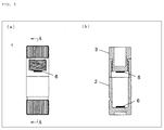
FIG. 3(a) is a side view of the column storage container illustrated inFIG. 1 , andFIG. 3(b) is a sectional view taken along the line A-A ofFIG. 3(a) . -
FIG. 4 is an illustration of an example of the column storage container of the present invention, in which only a part of a side wall of the container body is formed of a transparent material. -
FIG. 5 is an illustration of another example of the column storage container of the present invention. -
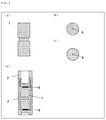
FIGS. 6 are each an illustration of an example of a chromatography column to be stored in the column storage container of the present invention.FIG. 6 (a) is a side view thereof.FIG. 6(b) is a top view thereof.FIG. 6(c) is a bottom view thereof.FIG. 6(d) is a conceptual diagram for illustrating a state of the chromatography column stored in the column storage container illustrated inFIG. 1 . -
FIGS. 7 are each a bottom view of acover 3 of thecolumn storage container 1 illustrated inFIG. 1 . - The present invention provides a storage container for storing a chromatography column, preferably, a liquid chromatography column such as a high-performance liquid chromatography (HPLC) column. There is no particular limitation on the size and shape of the chromatography column to be stored in the storage container of the present invention, and it is preferred that an external appearance of the chromatography column have a full length of from about 20 mm to about 80 mm and an outer diameter of from about 8 mm to about 12 mm from the viewpoint of a structure of the container of the present invention described later. Further, it is preferred that a fluid passage hole have a diameter of from about 0.1 mm to about 1.5 mm. Further, it is advantageous that an upper surface and a lower surface of the column are each a flat surface because the column can be supported stably in the container of the present invention. The storage container of the present invention is applicable to any of a column having a threaded groove on an inner wall of the fluid passage hole and a column having no threaded groove.
- The storage container of the present invention comprises: a container body for storing the chromatography column; and a cover threadedly engaging with the container body. A groove for threaded engagement threadedly engaging with the cover is formed in an inner wall of the container body. Further, a groove for threaded engagement, which is to be paired with the groove for threaded engagement of the container body and threadedly engages with an inner wall of the container body, is formed on a side surface of the cover. Thus, when the container body and the cover are threadedly engaged with each other, the cover enters the container body.
- The container body of the storage container of the present invention has such a size and a shape that the container body can store the chromatography column, and when the chromatography column is stored in the container, the chromatography column is allowed to stand by itself without tilting with respect to a center axis of the container body or falling down in the container by causing the container body having the column therein to stand upright. There is no particular limitation on the shape of an outer bottom surface of the container body, and the shape of the outer bottom surface of the container body is preferably such a shape as to enable the storage container to stand. Examples of the shape of the container body include a cylindrical shape, a polygonal column shape such as a hexagonal column shape or an octagonal column shape, or a tubular shape having a combination of the above-mentioned shapes (for example, a container body having an upper portion in a cylindrical shape and a lower portion in a polygonal column shape or a container body having an upper portion in a polygonal column shape and a lower portion in a cylindrical shape). Further, the function of preventing the container from rolling when the container falls down sideways can be further obtained by forming a part of the container body or an outer shape of the cover into a polygonal column shape. The minimum inner diameter of the container body is set to from about 101% to about 125%, preferably from about 101% to 115% of the outer diameter of the chromatography column to be stored.
- The cover of the storage container of the present invention may have a shape different from an outer shape of the container body as long as the cover has a threaded engagement portion having a groove for threaded engagement that can threadedly engage with the inner wall of the container body. For example, in the storage container of the present invention, the container body may have a cylindrical shape, and the cover may have a polygonal column shape such as a hexagonal column shape or an octagonal column shape. Alternatively, in the storage container of the present invention, the upper portion of the container body may have a cylindrical shape, and the lower portion of the container body and the cover may each have a polygonal column shape such as a hexagonal column shape or an octagonal column shape.
- Preferably, a non-slip portion may be formed on each of the container body and the cover. By virtue of the non-slip portion, when the container body and the cover are threadedly engaged with each other or the threaded engagement is released, the container body and the cover can be held easily, and the storage container of the present invention can be opened or closed easily. The non-slip portion maybe a groove, a protrusion, a large number of irregularities, or a surface made of a material having high friction, which is formed in at least a part of an outer surface of each of the container body and the cover. Further, it is preferred that an inner bottom surface of the container body and a lower surface of the cover be substantially flat surfaces because the column can be supported more stably in the container of the present invention.
- A sealing member is arranged on each of the inner bottom surface of the container body and a lower surface of the cover of the storage container of the present invention. The sealing member is formed of a material having high friction and elasticity, for example, an elastomer, such as an olefin-based elastomer or a styrene-based elastomer, a synthetic rubber, such as a fluoro-rubber, a nitrile rubber, a silicone rubber, a urethane rubber, or an ethylene propylene rubber, or a natural rubber. In one embodiment, the sealing member has a flat plate shape larger than the fluid passage hole of the column. In another embodiment, the sealing member has an O-ring shape having an outer diameter larger than that of the fluid passage hole but smaller than that of the upper surface or the lower surface of the column. In still another embodiment, one of the sealing members has the above-mentioned flat plate shape, and the other has the above-mentioned O-ring shape. Further, the shape of the sealing member is not limited to the above-mentioned embodiments as long as the sealing member can seal the fluid passage hole of the column, and any other shapes maybe used. In any case, the sealing member is arranged in each center on the inner bottom surface of the container body and the lower surface of the cover, and when the cover of the container of the present invention is closed as described later, the sealing member can be brought into close contact with at least a periphery of the fluid passage hole on each of the upper surface and the lower surface of the column.
- The sealing member serves to seal the fluid passage hole of the chromatography column stored in the storage container of the present invention, and to fix the column inside the storage container of the present invention. When the cover is closed in a state in which the chromatography column is stored in the container body of the storage container of the present invention, the cover is screwed into the container body, and hence the stored chromatography column is put into a state sandwiched between the inner bottom surface of the container body and the lower surface of the cover. In this case, two sealing members arranged on the inner bottom surface of the container body and the lower surface of the cover are each brought into close contact with at least the periphery of the fluid passage hole of the column on any of the upper surface and the lower surface of the column, to thereby seal the fluid passage hole. When the sealing member has, for example, a flat plate shape, through closing of the cover of the container, the fluid passage hole on the upper surface or the lower surface of the column is covered to be sealed with the sealing member. Further, when the sealing member has, for example, an O-ring shape, through closing of the cover of the container, the sealing member is brought into close contact with the periphery of the fluid passage hole of the upper surface or the lower surface of the column to surround the fluid passage hole together with the bottom surface of the container body or the lower surface of the cover, thereby being capable of sealing the fluid passage hole. Further, the two sealing members fix the column inside the container body by pressing the column from both the upper surface and the lower surface thereof.
- The sealing member formed of an elastic material further can serve to absorb shock from outside to the chromatography column stored in the storage container of the present invention. Thus, it is desired that the sealing member be thicker from the viewpoint of shock absorption. However, considering the economic viewpoint, the thickness of the sealing member is preferably from about 0.3 mm to 3.0 mm. In the case where the shock absorption of the sealing member is not sufficient for transportation or storage environment, the shock resistance can be enhanced more by covering the chromatography column stored in the storage container further with a buffer or the like.
- The container body and the cover of the storage container of the present invention each may be formed of a general-purpose resin, such as polymethyl methacrylate (PMMA), polypropylene (PP), polyethylene (PE), polycarbonate (PC), acrylonitrile-butadiene-styrene copolymer (ABS). It is preferred that at least a part of a side wall or an entire side wall of the container body be formed of a transparent or semi-transparent material so that the column stored in the storage container can be visually recognized. More preferably, the container body and the cover are formed of a transparent or semi-transparent material. Preferably, the storage container of the present invention is a self-standing type and can hold the stored column upright.
- The chromatography column stored in the storage container of the present invention is sealed and stably fixed inside the container with the cover through the sealing members having high friction and elasticity, and hence the chromatography column is protected from shock and contamination. Further, even when the cover of the storage container is opened, the column does not tilt or fall down in the container and is easily released from a fixed state, and the sealing can also be removed. Thus, the chromatography column of the present invention can be easily taken out of the container with a minimum operation without any risk of breakage and contamination, and can be set in a device.
- In addition to the above, according to the present invention, the use of the storage container of the present invention for storing the chromatography column is provided. There is also provided a method of storing the chromatography column through use of the storage container of the present invention. The details of the use and storage method are as described above.
- Hereinafter, embodiments of the present invention are further described in detail with reference to the drawings. Embodiments of the present invention illustrated in the drawings are merely examples of the present invention, and the present invention is not limited to those embodiments. Needless to say, in addition to the matters directly described in the embodiments, the present invention encompasses various improvements and modifications that may be made by a person skilled in the art within the scope of claims.
-
FIG. 1 is a perspective view of an example of a column storage container of the present invention. Acolumn storage container 1 according to this embodiment is a cylindrical self-standing container having a side wall formed of a transparent material, and a container body and a cover are threadedly engaged with each other. Acover 3 threadedly engaged with acontainer body 2 is placed inside thecontainer body 2. As a non-slip portion during opening/closing of the container, anon-slip groove 4 is formed in each of outer surfaces of thecover 3 and a lower portion of thecontainer body 2.FIG. 2 is an illustration of a state in which thecover 3 is removed from thecontainer body 2 in thecolumn storage container 1 illustrated inFIG. 1 . Groove for threadedengagements 5 to be paired are formed in an inner wall of thecontainer body 2 and a side surface of thecover 3. -
FIGS. 3 are a side view (FIG. 3a ) of thecolumn storage container 1 illustrated inFIG. 1 and a sectional view (FIG. 3b ) thereof. As illustrated inFIG. 3b , both an inner bottom surface of thecontainer body 2 and a lower surface of thecover 3 are a flat surface, and a sealingmember 6 is arranged on each of the inner bottom surface of thecontainer body 2 and the lower surface of thecover 3. In this embodiment, the sealingmember 6 is formed of a fluoro-rubber, and has a diameter larger than that of a fluid passage hole and a thickness of 1.5 mm. -
FIG. 4 is an illustration of an example of thecolumn storage container 1 of the present invention, in which only a center of the side wall of thecontainer body 2 is formed of a transparent material, and the others (shaded portions) are formed of a semi-transparent material. -
FIG. 5 is a perspective view of another example of the column storage container according to the present invention. In this embodiment, the shape of thecontainer body 2 is a combination of a cylindrical shape and a hexagonal column shape, and thecover 3 includes a head having a hexagonal column shape and a threaded engagement portion having a groove for threaded engagement. -
FIG. 6a to FIG. 6c are a side view (a), a top view (b), and a bottom view (c) of an example of achromatography column 7 to be stored in the column storage container of the present invention. Thecolumn 7 has a columnar shape, and an upper surface and a lower surface thereof are flat surfaces, each having afluid passage hole 8.FIG. 6d is a conceptual diagram for illustrating a state of thechromatography column 7 stored in thecolumn storage container 1 illustrated inFIG. 1 . The upper surface and the lower surface of thecolumn 7 are respectively held in close contact with the sealingmembers 6 arranged on the lower surface of thecover 3 and the inner bottom surface of thecontainer body 2. Thecolumn 7 is pressed from above and below through the two sealingmembers 6. With such press, thecolumn 7 is fixed inside thestorage container 1, and the fluid passage holes 8 formed in the upper surface and the lower surface of thecolumn 7 are sealed with the sealingmembers 6. -
FIGS. 7 are each a bottom view of thecover 3 of thecolumn storage container 1 ofFIG. 1 , and the sealingmember 6 is illustrated therein. InFIG. 7a , the sealingmember 6 has a disc shape having a diameter larger than that of the fluid passage hole and can cover and seal thefluid passage hole 8. InFIG. 7b , the sealingmember 6 has an O-ring shape having an outer diameter larger than that of the fluid passage hole and can seal thefluid passage hole 8 by surrounding a periphery of thefluid passage hole 8. -
- 1
- column storage container
- 2
- container body
- 3
- cover
- 4
- non-slip groove
- 5
- groove for threaded engagement
- 6
- sealing member
- 7
- chromatography column
- 8
- fluid passage hole
Claims (8)
- A chromatography column stored in a storage container,
the storage container comprising:a container body for storing the chromatography column; anda cover threadedly engaging with the container body,wherein the container body has a groove, which is formed in an inner wall thereof, for a threaded engagement of the container body and the cover,wherein the storage container further comprises sealing members arranged on an inner bottom surface of the container body and a lower surface of the cover, respectively, andwherein, when the container body and the cover are threadedly engaged with each other, the cover enters the container body to cause the sealing members on the inner bottom surface of the container body and the lower surface of the cover to press both a lower surface and an upper surface of the chromatography column, to thereby fix the chromatography column inside the container body and seal a fluid passage hole of the chromatography column. - The chromatography column according to claim 1, wherein the container body has a tubular shape having a minimum inner diameter of a size of from 101% to 125% of an outer diameter of the chromatography column.
- The chromatography column according to claim 1 or 2, wherein the sealing member comprises a flat plate or an O-ring formed of a material having high friction and elasticity.
- The chromatography column according to any one of claims 1 to 3, wherein the storage container comprises a self-standing container.
- A storage container for a chromatography column, comprising:a container body for storing the chromatography column; anda cover threadedly engaging with the container body;wherein the container body has a groove, which is formed in an inner wall thereof, for a threaded engagement of the container body and the cover,wherein the storage container further comprises sealing members arranged on an inner bottom surface of the container body and a lower surface of the cover, respectively, andwherein, when the container body and the cover are threadedly engaged with each other, the cover enters the container body to cause the sealing members on the inner bottom surface of the container body and the lower surface of the cover to press both a lower surface and an upper surface of the chromatography column, to thereby fix the chromatography column inside the container body and seal a fluid passage hole of the chromatography column.
- The storage container according to claim 5, wherein the container body has a tubular shape having a minimum inner diameter of a size of from 101% to 125% of an outer diameter of the chromatography column.
- The storage container according to claim 5 or 6, wherein the sealing member comprises a flat plate or an O-ring formed of a material having high friction and elasticity.
- The storage container according to any one of claims 5 to 7, wherein the storage container comprises a self-standing container.
Applications Claiming Priority (2)
| Application Number | Priority Date | Filing Date | Title |
|---|---|---|---|
| JP2013203036 | 2013-09-30 | ||
| PCT/JP2014/076053 WO2015046566A1 (en) | 2013-09-30 | 2014-09-30 | Column contained in container and column container |
Publications (3)
| Publication Number | Publication Date |
|---|---|
| EP3054294A1 true EP3054294A1 (en) | 2016-08-10 |
| EP3054294A4 EP3054294A4 (en) | 2017-05-10 |
| EP3054294B1 EP3054294B1 (en) | 2023-08-02 |
Family
ID=52743687
Family Applications (1)
| Application Number | Title | Priority Date | Filing Date |
|---|---|---|---|
| EP14849999.9A Active EP3054294B1 (en) | 2013-09-30 | 2014-09-30 | Column contained in container |
Country Status (5)
| Country | Link |
|---|---|
| US (1) | US9689848B2 (en) |
| EP (1) | EP3054294B1 (en) |
| JP (1) | JP6355640B2 (en) |
| CN (1) | CN105612425B (en) |
| WO (1) | WO2015046566A1 (en) |
Cited By (1)
| Publication number | Priority date | Publication date | Assignee | Title |
|---|---|---|---|---|
| GB2573386A (en) * | 2018-03-06 | 2019-11-06 | Jnc Corp | Vise for column and column system for chromatography |
Families Citing this family (2)
| Publication number | Priority date | Publication date | Assignee | Title |
|---|---|---|---|---|
| US11460452B2 (en) * | 2017-12-13 | 2022-10-04 | Regeneron Pharmaceuticals, Inc. | Devices and systems for chromatography column bed support management and related methods |
| CN109821273B (en) * | 2019-04-10 | 2023-08-25 | 军事科学院军事医学研究院环境医学与作业医学研究所 | A decompression and deblocking device for the enrichment of pathogenic microorganisms in water environment |
Family Cites Families (24)
| Publication number | Priority date | Publication date | Assignee | Title |
|---|---|---|---|---|
| DE2008354A1 (en) * | 1970-02-23 | 1971-09-09 | Boehnnger Mannheim GmbH, 6800 Mann heim | Combination column |
| US3904527A (en) * | 1975-02-18 | 1975-09-09 | Instrumentation Specialties Co | Chromatographic column |
| US4451364A (en) | 1982-03-03 | 1984-05-29 | Brownlee Labs Inc. | High pressure seal and coupling |
| GB8611950D0 (en) | 1986-05-16 | 1986-06-25 | Lucas Ind Plc | Gasoline injector |
| JPH0528518Y2 (en) * | 1986-07-31 | 1993-07-22 | ||
| CH674315A5 (en) | 1987-11-23 | 1990-05-31 | Werner Hafner | |
| JP2773569B2 (en) | 1992-09-17 | 1998-07-09 | 株式会社日立製作所 | Separation column, method for preventing deterioration of separation column, transportation method, handling method, and liquid for separation column |
| JP3345087B2 (en) | 1993-04-16 | 2002-11-18 | 東ソー株式会社 | Plastic plug for liquid chromatography column |
| JP3975575B2 (en) * | 1998-09-11 | 2007-09-12 | 株式会社島津製作所 | column |
| CN2400380Y (en) | 1999-11-10 | 2000-10-11 | 曹建华 | multifunctional tubular container |
| US6387256B1 (en) | 2000-07-10 | 2002-05-14 | Waters Investments Limited | Chromatography column |
| CN2553381Y (en) | 2002-07-24 | 2003-05-28 | 中国科学院大连化学物理研究所 | High efficient liquid phase chromatographic column |
| US7575676B2 (en) | 2003-04-14 | 2009-08-18 | Waters Technologies Corporation | HPLC column holder apparatus |
| DE102005024154B3 (en) * | 2005-05-23 | 2007-02-08 | Bischoff Analysentechnik und -geräte GmbH | Elements for separation of substances by distribution between a stationary and a mobile phase and method for producing a separation device |
| JP3957078B1 (en) * | 2005-05-24 | 2007-08-08 | ヘラマンタイトン株式会社 | Cartridge column |
| US7704388B2 (en) | 2006-01-31 | 2010-04-27 | Luknova, Inc | Reusable liquid chromatographic columns |
| US8197694B1 (en) | 2010-03-30 | 2012-06-12 | Chaodong Jin | Safe transportation and storage for capillary columns |
| CN201882145U (en) | 2010-09-30 | 2011-06-29 | 芜湖南大汽车工业有限公司 | Automobile pull rod assembly |
| CN201882415U (en) * | 2010-12-13 | 2011-06-29 | 刘明 | Flexible inflatable container for storing fragile cylinders |
| JP4800448B1 (en) | 2011-03-30 | 2011-10-26 | カンナル印刷株式会社 | Holder for rod-shaped member and package |
| JP2013047880A (en) | 2011-08-29 | 2013-03-07 | Fujitsu Frontech Ltd | Wireless tag |
| CN202389710U (en) | 2011-12-31 | 2012-08-22 | 周亢 | Packing box |
| US9778232B2 (en) * | 2013-03-11 | 2017-10-03 | Sekisui Medical Co., Ltd. | Column device for liquid chromatography and liquid chromatography apparatus |
| CN203342439U (en) * | 2013-06-08 | 2013-12-18 | 武汉华纳联合药业有限公司 | Chromatographic column |
-
2014
- 2014-09-30 CN CN201480053521.1A patent/CN105612425B/en active Active
- 2014-09-30 EP EP14849999.9A patent/EP3054294B1/en active Active
- 2014-09-30 WO PCT/JP2014/076053 patent/WO2015046566A1/en not_active Ceased
- 2014-09-30 JP JP2015539455A patent/JP6355640B2/en active Active
- 2014-09-30 US US15/026,175 patent/US9689848B2/en active Active
Cited By (3)
| Publication number | Priority date | Publication date | Assignee | Title |
|---|---|---|---|---|
| GB2573386A (en) * | 2018-03-06 | 2019-11-06 | Jnc Corp | Vise for column and column system for chromatography |
| US11097208B2 (en) | 2018-03-06 | 2021-08-24 | Jnc Corporation | Vise for column and column system for chromatography |
| GB2573386B (en) * | 2018-03-06 | 2022-12-07 | Jnc Corp | Vise for column and column system for chromatography |
Also Published As
| Publication number | Publication date |
|---|---|
| JPWO2015046566A1 (en) | 2017-03-09 |
| CN105612425A (en) | 2016-05-25 |
| CN105612425B (en) | 2017-08-08 |
| JP6355640B2 (en) | 2018-07-11 |
| US20160223501A1 (en) | 2016-08-04 |
| EP3054294A4 (en) | 2017-05-10 |
| WO2015046566A1 (en) | 2015-04-02 |
| EP3054294B1 (en) | 2023-08-02 |
| US9689848B2 (en) | 2017-06-27 |
Similar Documents
| Publication | Publication Date | Title |
|---|---|---|
| JP6760950B2 (en) | Rotation guaranteed rack | |
| US4942966A (en) | Containment device for a test tube | |
| US9757306B2 (en) | Vial container with collar cap | |
| CA2905741A1 (en) | Vial container with collar cap | |
| EP3054294B1 (en) | Column contained in container | |
| US10562696B2 (en) | Container for storing and individually discharging capsules | |
| CN103747768B (en) | Liquid container | |
| US9764877B2 (en) | Capped container | |
| US9499310B2 (en) | Combination child-resistant package and collapsible tube, and method of using same | |
| JP2016033033A (en) | Tablet container | |
| US20140154153A1 (en) | Test Specimen Holding Device for Inspecting Sterilization or Cleaning Processes | |
| EP2216265A1 (en) | Containment for bottles, vials and like containers | |
| KR101987714B1 (en) | Marinelli Beaker for Gamm Spectroscopy with a Screw type Hermetic Cap | |
| KR102211201B1 (en) | Airtight Container for Radioactivity Measurement Such as Radon Using Gamma-ray Spectrometer | |
| KR102812025B1 (en) | Double packaging for object intended to remain sterile | |
| JP6836235B2 (en) | Cell transport container | |
| RU122987U1 (en) | VESSEL CAP | |
| US20200017275A1 (en) | Container for photosensitive material | |
| KR101465439B1 (en) | Storage Container For Solid State Sample | |
| HU224342B1 (en) | Transport packaging for bottle | |
| CN108514900B (en) | Reagent bottle | |
| GB201209315D0 (en) | Storage bottle with multiple compartments | |
| KR20150109044A (en) | container set | |
| KR20090005611U (en) | Containers set | |
| TH14588C3 (en) | Blood Sampling Cylinder for Transport |
Legal Events
| Date | Code | Title | Description |
|---|---|---|---|
| PUAI | Public reference made under article 153(3) epc to a published international application that has entered the european phase |
Free format text: ORIGINAL CODE: 0009012 |
|
| 17P | Request for examination filed |
Effective date: 20160406 |
|
| AK | Designated contracting states |
Kind code of ref document: A1 Designated state(s): AL AT BE BG CH CY CZ DE DK EE ES FI FR GB GR HR HU IE IS IT LI LT LU LV MC MK MT NL NO PL PT RO RS SE SI SK SM TR |
|
| AX | Request for extension of the european patent |
Extension state: BA ME |
|
| DAX | Request for extension of the european patent (deleted) | ||
| A4 | Supplementary search report drawn up and despatched |
Effective date: 20170407 |
|
| RIC1 | Information provided on ipc code assigned before grant |
Ipc: G01N 30/60 20060101AFI20170403BHEP Ipc: B01D 15/20 20060101ALN20170403BHEP |
|
| STAA | Information on the status of an ep patent application or granted ep patent |
Free format text: STATUS: EXAMINATION IS IN PROGRESS |
|
| 17Q | First examination report despatched |
Effective date: 20210423 |
|
| GRAP | Despatch of communication of intention to grant a patent |
Free format text: ORIGINAL CODE: EPIDOSNIGR1 |
|
| STAA | Information on the status of an ep patent application or granted ep patent |
Free format text: STATUS: GRANT OF PATENT IS INTENDED |
|
| INTG | Intention to grant announced |
Effective date: 20230302 |
|
| RIN1 | Information on inventor provided before grant (corrected) |
Inventor name: MURAKI, HIDEKI Inventor name: NEMOTO, YURIKO Inventor name: YOTANI, TAKUYA |
|
| GRAS | Grant fee paid |
Free format text: ORIGINAL CODE: EPIDOSNIGR3 |
|
| GRAA | (expected) grant |
Free format text: ORIGINAL CODE: 0009210 |
|
| STAA | Information on the status of an ep patent application or granted ep patent |
Free format text: STATUS: THE PATENT HAS BEEN GRANTED |
|
| P01 | Opt-out of the competence of the unified patent court (upc) registered |
Effective date: 20230621 |
|
| RAP3 | Party data changed (applicant data changed or rights of an application transferred) |
Owner name: SEKISUI MEDICAL CO., LTD. |
|
| AK | Designated contracting states |
Kind code of ref document: B1 Designated state(s): AL AT BE BG CH CY CZ DE DK EE ES FI FR GB GR HR HU IE IS IT LI LT LU LV MC MK MT NL NO PL PT RO RS SE SI SK SM TR |
|
| REG | Reference to a national code |
Ref country code: GB Ref legal event code: FG4D |
|
| REG | Reference to a national code |
Ref country code: CH Ref legal event code: EP |
|
| REG | Reference to a national code |
Ref country code: DE Ref legal event code: R096 Ref document number: 602014087857 Country of ref document: DE |
|
| REG | Reference to a national code |
Ref country code: IE Ref legal event code: FG4D |
|
| REG | Reference to a national code |
Ref country code: LT Ref legal event code: MG9D |
|
| REG | Reference to a national code |
Ref country code: NL Ref legal event code: MP Effective date: 20230802 |
|
| REG | Reference to a national code |
Ref country code: AT Ref legal event code: MK05 Ref document number: 1595352 Country of ref document: AT Kind code of ref document: T Effective date: 20230802 |
|
| PG25 | Lapsed in a contracting state [announced via postgrant information from national office to epo] |
Ref country code: GR Free format text: LAPSE BECAUSE OF FAILURE TO SUBMIT A TRANSLATION OF THE DESCRIPTION OR TO PAY THE FEE WITHIN THE PRESCRIBED TIME-LIMIT Effective date: 20231103 |
|
| PG25 | Lapsed in a contracting state [announced via postgrant information from national office to epo] |
Ref country code: IS Free format text: LAPSE BECAUSE OF FAILURE TO SUBMIT A TRANSLATION OF THE DESCRIPTION OR TO PAY THE FEE WITHIN THE PRESCRIBED TIME-LIMIT Effective date: 20231202 |
|
| PG25 | Lapsed in a contracting state [announced via postgrant information from national office to epo] |
Ref country code: SE Free format text: LAPSE BECAUSE OF FAILURE TO SUBMIT A TRANSLATION OF THE DESCRIPTION OR TO PAY THE FEE WITHIN THE PRESCRIBED TIME-LIMIT Effective date: 20230802 Ref country code: RS Free format text: LAPSE BECAUSE OF FAILURE TO SUBMIT A TRANSLATION OF THE DESCRIPTION OR TO PAY THE FEE WITHIN THE PRESCRIBED TIME-LIMIT Effective date: 20230802 Ref country code: PT Free format text: LAPSE BECAUSE OF FAILURE TO SUBMIT A TRANSLATION OF THE DESCRIPTION OR TO PAY THE FEE WITHIN THE PRESCRIBED TIME-LIMIT Effective date: 20231204 Ref country code: NO Free format text: LAPSE BECAUSE OF FAILURE TO SUBMIT A TRANSLATION OF THE DESCRIPTION OR TO PAY THE FEE WITHIN THE PRESCRIBED TIME-LIMIT Effective date: 20231102 Ref country code: NL Free format text: LAPSE BECAUSE OF FAILURE TO SUBMIT A TRANSLATION OF THE DESCRIPTION OR TO PAY THE FEE WITHIN THE PRESCRIBED TIME-LIMIT Effective date: 20230802 Ref country code: LV Free format text: LAPSE BECAUSE OF FAILURE TO SUBMIT A TRANSLATION OF THE DESCRIPTION OR TO PAY THE FEE WITHIN THE PRESCRIBED TIME-LIMIT Effective date: 20230802 Ref country code: LT Free format text: LAPSE BECAUSE OF FAILURE TO SUBMIT A TRANSLATION OF THE DESCRIPTION OR TO PAY THE FEE WITHIN THE PRESCRIBED TIME-LIMIT Effective date: 20230802 Ref country code: IS Free format text: LAPSE BECAUSE OF FAILURE TO SUBMIT A TRANSLATION OF THE DESCRIPTION OR TO PAY THE FEE WITHIN THE PRESCRIBED TIME-LIMIT Effective date: 20231202 Ref country code: HR Free format text: LAPSE BECAUSE OF FAILURE TO SUBMIT A TRANSLATION OF THE DESCRIPTION OR TO PAY THE FEE WITHIN THE PRESCRIBED TIME-LIMIT Effective date: 20230802 Ref country code: GR Free format text: LAPSE BECAUSE OF FAILURE TO SUBMIT A TRANSLATION OF THE DESCRIPTION OR TO PAY THE FEE WITHIN THE PRESCRIBED TIME-LIMIT Effective date: 20231103 Ref country code: FI Free format text: LAPSE BECAUSE OF FAILURE TO SUBMIT A TRANSLATION OF THE DESCRIPTION OR TO PAY THE FEE WITHIN THE PRESCRIBED TIME-LIMIT Effective date: 20230802 Ref country code: AT Free format text: LAPSE BECAUSE OF FAILURE TO SUBMIT A TRANSLATION OF THE DESCRIPTION OR TO PAY THE FEE WITHIN THE PRESCRIBED TIME-LIMIT Effective date: 20230802 |
|
| PG25 | Lapsed in a contracting state [announced via postgrant information from national office to epo] |
Ref country code: PL Free format text: LAPSE BECAUSE OF FAILURE TO SUBMIT A TRANSLATION OF THE DESCRIPTION OR TO PAY THE FEE WITHIN THE PRESCRIBED TIME-LIMIT Effective date: 20230802 |
|
| PG25 | Lapsed in a contracting state [announced via postgrant information from national office to epo] |
Ref country code: ES Free format text: LAPSE BECAUSE OF FAILURE TO SUBMIT A TRANSLATION OF THE DESCRIPTION OR TO PAY THE FEE WITHIN THE PRESCRIBED TIME-LIMIT Effective date: 20230802 |
|
| PG25 | Lapsed in a contracting state [announced via postgrant information from national office to epo] |
Ref country code: SM Free format text: LAPSE BECAUSE OF FAILURE TO SUBMIT A TRANSLATION OF THE DESCRIPTION OR TO PAY THE FEE WITHIN THE PRESCRIBED TIME-LIMIT Effective date: 20230802 Ref country code: RO Free format text: LAPSE BECAUSE OF FAILURE TO SUBMIT A TRANSLATION OF THE DESCRIPTION OR TO PAY THE FEE WITHIN THE PRESCRIBED TIME-LIMIT Effective date: 20230802 Ref country code: ES Free format text: LAPSE BECAUSE OF FAILURE TO SUBMIT A TRANSLATION OF THE DESCRIPTION OR TO PAY THE FEE WITHIN THE PRESCRIBED TIME-LIMIT Effective date: 20230802 Ref country code: EE Free format text: LAPSE BECAUSE OF FAILURE TO SUBMIT A TRANSLATION OF THE DESCRIPTION OR TO PAY THE FEE WITHIN THE PRESCRIBED TIME-LIMIT Effective date: 20230802 Ref country code: DK Free format text: LAPSE BECAUSE OF FAILURE TO SUBMIT A TRANSLATION OF THE DESCRIPTION OR TO PAY THE FEE WITHIN THE PRESCRIBED TIME-LIMIT Effective date: 20230802 Ref country code: CZ Free format text: LAPSE BECAUSE OF FAILURE TO SUBMIT A TRANSLATION OF THE DESCRIPTION OR TO PAY THE FEE WITHIN THE PRESCRIBED TIME-LIMIT Effective date: 20230802 Ref country code: SK Free format text: LAPSE BECAUSE OF FAILURE TO SUBMIT A TRANSLATION OF THE DESCRIPTION OR TO PAY THE FEE WITHIN THE PRESCRIBED TIME-LIMIT Effective date: 20230802 |
|
| REG | Reference to a national code |
Ref country code: CH Ref legal event code: PL |
|
| REG | Reference to a national code |
Ref country code: DE Ref legal event code: R097 Ref document number: 602014087857 Country of ref document: DE |
|
| PG25 | Lapsed in a contracting state [announced via postgrant information from national office to epo] |
Ref country code: LU Free format text: LAPSE BECAUSE OF NON-PAYMENT OF DUE FEES Effective date: 20230930 |
|
| REG | Reference to a national code |
Ref country code: BE Ref legal event code: MM Effective date: 20230930 |
|
| PG25 | Lapsed in a contracting state [announced via postgrant information from national office to epo] |
Ref country code: LU Free format text: LAPSE BECAUSE OF NON-PAYMENT OF DUE FEES Effective date: 20230930 Ref country code: MC Free format text: LAPSE BECAUSE OF FAILURE TO SUBMIT A TRANSLATION OF THE DESCRIPTION OR TO PAY THE FEE WITHIN THE PRESCRIBED TIME-LIMIT Effective date: 20230802 |
|
| PLBE | No opposition filed within time limit |
Free format text: ORIGINAL CODE: 0009261 |
|
| STAA | Information on the status of an ep patent application or granted ep patent |
Free format text: STATUS: NO OPPOSITION FILED WITHIN TIME LIMIT |
|
| REG | Reference to a national code |
Ref country code: IE Ref legal event code: MM4A |
|
| PG25 | Lapsed in a contracting state [announced via postgrant information from national office to epo] |
Ref country code: IE Free format text: LAPSE BECAUSE OF NON-PAYMENT OF DUE FEES Effective date: 20230930 |
|
| 26N | No opposition filed |
Effective date: 20240503 |
|
| PG25 | Lapsed in a contracting state [announced via postgrant information from national office to epo] |
Ref country code: CH Free format text: LAPSE BECAUSE OF NON-PAYMENT OF DUE FEES Effective date: 20230930 |
|
| PG25 | Lapsed in a contracting state [announced via postgrant information from national office to epo] |
Ref country code: IE Free format text: LAPSE BECAUSE OF NON-PAYMENT OF DUE FEES Effective date: 20230930 Ref country code: CH Free format text: LAPSE BECAUSE OF NON-PAYMENT OF DUE FEES Effective date: 20230930 Ref country code: SI Free format text: LAPSE BECAUSE OF FAILURE TO SUBMIT A TRANSLATION OF THE DESCRIPTION OR TO PAY THE FEE WITHIN THE PRESCRIBED TIME-LIMIT Effective date: 20230802 |
|
| PG25 | Lapsed in a contracting state [announced via postgrant information from national office to epo] |
Ref country code: BE Free format text: LAPSE BECAUSE OF NON-PAYMENT OF DUE FEES Effective date: 20230930 |
|
| PG25 | Lapsed in a contracting state [announced via postgrant information from national office to epo] |
Ref country code: BG Free format text: LAPSE BECAUSE OF FAILURE TO SUBMIT A TRANSLATION OF THE DESCRIPTION OR TO PAY THE FEE WITHIN THE PRESCRIBED TIME-LIMIT Effective date: 20230802 |
|
| PG25 | Lapsed in a contracting state [announced via postgrant information from national office to epo] |
Ref country code: BG Free format text: LAPSE BECAUSE OF FAILURE TO SUBMIT A TRANSLATION OF THE DESCRIPTION OR TO PAY THE FEE WITHIN THE PRESCRIBED TIME-LIMIT Effective date: 20230802 |
|
| PG25 | Lapsed in a contracting state [announced via postgrant information from national office to epo] |
Ref country code: CY Free format text: LAPSE BECAUSE OF FAILURE TO SUBMIT A TRANSLATION OF THE DESCRIPTION OR TO PAY THE FEE WITHIN THE PRESCRIBED TIME-LIMIT; INVALID AB INITIO Effective date: 20140930 |
|
| PG25 | Lapsed in a contracting state [announced via postgrant information from national office to epo] |
Ref country code: HU Free format text: LAPSE BECAUSE OF FAILURE TO SUBMIT A TRANSLATION OF THE DESCRIPTION OR TO PAY THE FEE WITHIN THE PRESCRIBED TIME-LIMIT; INVALID AB INITIO Effective date: 20140930 |
|
| PGFP | Annual fee paid to national office [announced via postgrant information from national office to epo] |
Ref country code: DE Payment date: 20250805 Year of fee payment: 12 |
|
| PGFP | Annual fee paid to national office [announced via postgrant information from national office to epo] |
Ref country code: IT Payment date: 20250825 Year of fee payment: 12 |
|
| PGFP | Annual fee paid to national office [announced via postgrant information from national office to epo] |
Ref country code: GB Payment date: 20250807 Year of fee payment: 12 |
|
| PGFP | Annual fee paid to national office [announced via postgrant information from national office to epo] |
Ref country code: FR Payment date: 20250808 Year of fee payment: 12 |
|
| PG25 | Lapsed in a contracting state [announced via postgrant information from national office to epo] |
Ref country code: TR Free format text: LAPSE BECAUSE OF FAILURE TO SUBMIT A TRANSLATION OF THE DESCRIPTION OR TO PAY THE FEE WITHIN THE PRESCRIBED TIME-LIMIT Effective date: 20230802 |