EP3054269B1 - Rotation angle sensor - Google Patents
Rotation angle sensor Download PDFInfo
- Publication number
- EP3054269B1 EP3054269B1 EP13894902.9A EP13894902A EP3054269B1 EP 3054269 B1 EP3054269 B1 EP 3054269B1 EP 13894902 A EP13894902 A EP 13894902A EP 3054269 B1 EP3054269 B1 EP 3054269B1
- Authority
- EP
- European Patent Office
- Prior art keywords
- shaft member
- rotation
- rotation angle
- shaft
- angle sensor
- Prior art date
- Legal status (The legal status is an assumption and is not a legal conclusion. Google has not performed a legal analysis and makes no representation as to the accuracy of the status listed.)
- Active
Links
Images




Classifications
-
- G—PHYSICS
- G01—MEASURING; TESTING
- G01D—MEASURING NOT SPECIALLY ADAPTED FOR A SPECIFIC VARIABLE; ARRANGEMENTS FOR MEASURING TWO OR MORE VARIABLES NOT COVERED IN A SINGLE OTHER SUBCLASS; TARIFF METERING APPARATUS; MEASURING OR TESTING NOT OTHERWISE PROVIDED FOR
- G01D5/00—Mechanical means for transferring the output of a sensing member; Means for converting the output of a sensing member to another variable where the form or nature of the sensing member does not constrain the means for converting; Transducers not specially adapted for a specific variable
- G01D5/12—Mechanical means for transferring the output of a sensing member; Means for converting the output of a sensing member to another variable where the form or nature of the sensing member does not constrain the means for converting; Transducers not specially adapted for a specific variable using electric or magnetic means
- G01D5/14—Mechanical means for transferring the output of a sensing member; Means for converting the output of a sensing member to another variable where the form or nature of the sensing member does not constrain the means for converting; Transducers not specially adapted for a specific variable using electric or magnetic means influencing the magnitude of a current or voltage
- G01D5/142—Mechanical means for transferring the output of a sensing member; Means for converting the output of a sensing member to another variable where the form or nature of the sensing member does not constrain the means for converting; Transducers not specially adapted for a specific variable using electric or magnetic means influencing the magnitude of a current or voltage using Hall-effect devices
- G01D5/145—Mechanical means for transferring the output of a sensing member; Means for converting the output of a sensing member to another variable where the form or nature of the sensing member does not constrain the means for converting; Transducers not specially adapted for a specific variable using electric or magnetic means influencing the magnitude of a current or voltage using Hall-effect devices influenced by the relative movement between the Hall device and magnetic fields
Definitions
- the disclosure is related to a rotation angle sensor.
- a rotation detection apparatus is known (see Patent Literature 1, for example) in which a magnetic flux generating member is provided such that the magnetic flux generating member rotates together with a main rotation axis due to a rotation of an object to be detected, and a detection signal according to the rotation of the object is output using a magnetoelectric device that detects magnitude of the magnetic flux that changes according to the rotation of the magnetic flux generating member.
- a magnetoelectric device that detects magnitude of the magnetic flux that changes according to the rotation of the magnetic flux generating member.
- Another rotation angle sensor is known from US2012/0210816 .
- an input rotary shaft is directly inserted into the magnetic flux generating member to be held therein; however, there may be a case where a manufacturing error, etc., causes decentering of the input rotary shaft with respect to the rotation axis of the magnetic flux generating member.
- a manufacturing error, etc. causes decentering of the input rotary shaft with respect to the rotation axis of the magnetic flux generating member.
- prying occurs, which may easily cause damage of the magnetic flux generating member and thus reduce durability of the magnetic flux generating member.
- the shift between the rotation axis of the magnetic flux generating member and a sensor center is not rectified, which can prevent the damage of the magnetic flux generating member, the shift causes a reduced detection accuracy of the rotation angle.
- a rotation angle sensor which includes:
- a rotation angle sensor can be obtained that enables reducing prying due to a decentering of an input rotary shaft, while ensuring high detection accuracy of a rotation angle.
- Fig. 1 is a exploded perspective view of a rotation angle sensor 1 according to an embodiment.
- Fig. 2 is a cross-sectional view of the rotation angle sensor 1.
- Fig. 3 is a cross-sectional view of the rotation angle sensor 1.
- Fig. 4 is a diagram explaining a center O (i.e., a detection axis) of the rotation angle sensor 1, in which (A) is top view illustrating an example of a detection element 40, and (B) illustrates a relationship between the center O of the rotation angle sensor 1 and a center O' of a magnetic flux generating part 24. It is noted that, in Fig. 1 , an example of an input rotary shaft 90 is illustrated together with the rotation angle sensor 1.
- an axial direction corresponds to a direction in which the input rotary shaft 90 extends.
- Y direction and X direction are perpendicular to the axial direction, and are perpendicular to each other.
- the rotation angle sensor 1 may be mounted in an arbitrary orientation; however, in the following, for the sake of convenience, it is assumed that an "upper side” corresponds to an upper side of the axial direction in Fig. 2 . It is noted that in the present specification, “play” means play in a mechanism, and “play” is different from a clearance for a design tolerance, a manufacturing tolerance, etc.
- the rotation angle sensor 1 detects a rotation angle (i.e., a rotation position) of the input rotary shaft 90.
- the input rotary shaft 90 may be any one of rotation members in a vehicle (including a car, a two-wheeled vehicle, construction equipment, etc.).
- the input rotary shaft 90 may be a rotation axis of a drive mechanism (a transmission, for example), or a rotation axis of a steering mechanism (a steering shaft, for example).
- the rotation angle sensor 1 includes a first shaft member 10, a second shaft member 20, a rotation guide member 30, a detection element 40, and a lid member 50.
- the first shaft member 10 may be formed of a resin.
- the first shaft member 10 includes a slot 14 (longer in Y direction) into which the input rotary shaft 90 is inserted.
- the first shaft member 10 holds the input rotary shaft 90 to rotate with the input rotary shaft 90.
- the first shaft member 10 holds the input rotary shaft 90 such that the input rotary shaft 90 has play in Y direction.
- a dimension of the slot 14 in Y direction is substantially longer than a length of an end of the input rotary shaft 90 in Y direction.
- a range of the movement in Y direction is arbitrary, and may correspond to a range of a possible shift (decentering) amount of the input rotary shaft 90 with respect to the center O of the rotation angle sensor 1 in Y direction due to the manufacturing tolerance, etc.
- An example of a construction of the first shaft member 10 is described hereinafter.
- the second shaft member 20 may be formed of a resin.
- the second shaft member 20 is provided such that the first shaft member 10 is seated on an upper surface of the second shaft member 20 in the axial direction, and a lower surface of the second shaft member 20 is seated on the rotation guide member 30.
- the second shaft member 20 holds the first shaft member 10 to rotate with the first shaft member 10.
- the second shaft member 20 holds the first shaft member 10 such that the first shaft member 10 has play in X direction. In other words, the first shaft member 10 can move in X direction while the rotation thereof with respect to the second shaft member 20 is restrained.
- a range of the movement in X direction is arbitrary, and may correspond to a range of a possible shift (decentering) amount of the input rotary shaft 90 with respect to the center O of the rotation angle sensor 1 in X direction due to the manufacturing tolerance, etc.
- the second shaft member 20 includes a magnetic flux generating part 24 and a body part 26.
- the magnetic flux generating part 24 is provided to be concentric with the center O of the rotation angle sensor 1, and may be a circular part that is concentric with the center O of the rotation angle sensor 1, as illustrated in Fig. 2 .
- the magnetic flux generating part 24 may be equally parted in a diameter direction viewed from top such that the parted portions form a south pole and a north pole, respectively (see Fig. 4 (B) ).
- the magnetic flux generating part 24 may be a magnet embedded in the body part 26 of the second shaft member 20.
- the magnetic flux generating part 24 may be integrally formed with the body part 26 using a resin material including magnetic particles (neodymium-based magnetic particles, for example).
- the body part 26 surrounds the magnetic flux generating part 24.
- the rotation guide member 30 may be formed of a resin.
- the rotation guide member 30 rotatably supports the second shaft member 20.
- the rotation guide member 30 guides the rotation of the second shaft member 20 to define the rotation center of the second shaft member 20.
- this guide mechanism is based on an engagement between a guide channel 22 and a protrusion 32, as illustrated in Fig. 1 , etc., for example.
- a surface of the rotation guide member 30 on a side on which the second shaft member 20 is seated has the protrusion 32, as illustrated in Fig. 1 .
- the protrusion 32 has a circular form viewed along the axial direction.
- a surface of the second shaft member 20 on a side that is seated on the rotation guide member 30 has the guide channel 22 formed therein in a circular form viewed along the axial direction.
- the second shaft member 20 is provided on the rotation guide member 30 such that the protrusion 32 of the rotation guide member 30 is engaged in the guide channel 22 of the second shaft member 20.
- the second shaft member 20 can rotate and slide on the rotation guide member 30 such that the protrusion 32 is guided in the guide channel 22.
- a center of the rotation of the second shaft member 20 corresponds to a center of the circular shape of the guide channel 22.
- the circular shape of the guide channel 22 is set to have its center at the center O of the rotation angle sensor 1.
- the protrusion 32 has a clearance in the guide channel 22 such that the second shaft member 20 can smoothly rotate with respect to the rotation guide member 30.
- the rotation guide member 30 and/or the second shaft member 20 may be formed of a resin material in which polytetrafluoroethylene (PTFE) is compounded. Alternatively, from the same view point, the rotation guide member 30 and/or the second shaft member 20 may have sliding surfaces coated.
- the guide mechanism based on the engagement between the guide channel 22 and the protrusion 32 is used; however, other guide mechanisms may be used.
- the guide channel 22 may be a cylindrical column-shaped channel (concave portion) obtained by cutting away an inner portion in a radius direction.
- the protrusion 32 may be a cylindrical column-shaped protrusion that is engaged in the cylindrically shaped channel.
- the detection element 40 is opposed to the magnetic flux generating part 24 of the second shaft member 20 via the rotation guide member 30 to detect the magnetic flux according to the rotation angle of the second shaft member 20.
- the detection axis of the detection element 40 i.e., a center of a rotation detection
- the detection axis of the detection element 40 corresponds to an original position O of a coordinate system defined by x and y axes.
- the detection axis of the detection element 40 is a point at which the detection accuracy (sensitivity) becomes the best when the center 0' of the magnet (see Fig. 4 (B) ) is aligned therewith, and the detection axis of the detection element 40 does not necessarily correspond to a physical center of the detection element 40. It is noted that the center O' of the magnet corresponds to the rotation center of the magnetic flux generating part 24.
- the detection element 40 may be a Hall element, a MR (Magneto Resistance) element (magneto-resistance effect element), etc.
- the detection element 40 may be in a chip form as illustrated in Fig. 4 , and may be installed on a substrate 42 as illustrated in Fig. 2 .
- An electrical signal from the detection element 40 may be input to an external apparatus (an on-vehicle ECU (Electronic Control Unit), for example) via a communication line in a cable 80.
- an external apparatus an on-vehicle ECU (Electronic Control Unit), for example
- the rotation guide member 30 has an internal space 30a and the detection element 40 installed on the substrate 42 is disposed in the internal space 30a.
- the internal space 30a may be filled with a resin (epoxy resin, for example).
- the lid member 50 is cylindrical-shaped, as illustrated in Fig. 1 , etc., and may be formed of a resin.
- the lid member 50 is secured to the rotation guide member 30.
- the lid member 50 may be secured to the rotation guide member 30 with adhesive, welding, etc.
- the lid member 50 accommodates the first shaft member 10 and the second shaft member 20 therein.
- the lid member 50 has an upper portion with an opening such that the slot 14 of the first shaft member 10 is exposed as a whole viewed from top.
- the lid member 50 comes in contact with the upper surface of the first shaft member 10 in the axial direction to restrain displacements of the first shaft member 10 and the second shaft member 20 with respect to the rotation guide member 30.
- the lid member 50 restrains the movement of the first shaft member 10 and the second shaft member 20 in the axial direction while permitting the rotation of the first shaft member 10 and the second shaft member 20.
- the engagement between the first shaft member 10 and the second shaft member 20 i.e., the engagement between a key 18 and a key channel 28 described hereinafter
- the engagement between the second shaft member 20 and the rotation guide member 30 i.e., the engagement between the guide channel 22 and the protrusion 32
- the lid member 50 comes in contact with the upper surfaces 10a, 20a of the first shaft member 10 and the second shaft member 20 in the axial direction, respectively, to directly restrain the movements of the first shaft member 10 and the second shaft member 20 in the axial direction. Further, in the example illustrated in Fig. 2 , the lid member 50 also comes in contact with the key 18 (described hereinafter) in the axial direction. It is noted that, the contact manner described above is an example. For example, the lid member 50 may not come in direct contact with the second shaft member 20. In this case, the lid member 50 may come in contact with the first shaft member 10 to indirectly constrain the movement of the second shaft member 20 in the axial direction.
- Fig. 5 is a single item view illustrating the first shaft member 10, in which (A) is a top view, (B) is a sectional-view, (C) is a bottom view, and (D) is a side view.
- the first shaft member 10 is cylindrical-shaped as a whole.
- the first shaft member 10 includes the slot 14 into which the input rotary shaft 90 is inserted, as described above.
- the slot 14 has a shape corresponding to the end portion of the input rotary shaft 90, and is substantially longer than the end portion of the input rotary shaft 90 in Y direction, as described above.
- the width of the slot 14 in X distance may be substantially the same as the width of the input rotary shaft 90 in X direction (i.e., there is no play between the slot 14 and the input rotary shaft 90 in X direction). In the example illustrated in Fig.
- the end portion of the input rotary shaft 90 is cut to have two faces (obtained by cutting a cylindrical column with two parallel faces), and accordingly the slot 14 is formed to have a substantially rectangular shape. More specifically, the slot 14 defines a cylindrical column space with a predetermined radius R1 that has two faces 14a, 14b cut therein such that the faces 14a, 14b are parallel with Y direction and the axial direction. Further, the faces 14a, 14b are symmetrical with respect to a center axis of the cylindrical column space.
- the predetermined radius R1 is set such that the predetermined radius R1 is greater than a radius (i.e., a radius of the cylindrical column before the two faces 14a, 14b have been cut) of the end portion of the input rotary shaft 90 by an amount of necessary play, for example.
- the face 14b includes a concave surface 14c; however, such a concave surface 14c may be omitted.
- the concave surface 14c is provided for a convex surface 90a of the input rotary shaft 90 to define the insertion orientation of the input rotary shaft 90.
- the slot 14 is a penetrating hole through the first shaft member 10 in the axial direction; however, the slot 14 may be a non-penetrating hole with a bottom. It is noted that, in the case where the slot 14 is a penetrating hole, the input rotary shaft 90 passes through the slot 14 to have a tip end surface be in contact with the upper surface of a concave portion 29 of the second shaft member 20. Again, in this case, the rotation of the input rotary shaft 90 is transmitted to the second shaft member 20 not directly but via the first shaft member 10.
- the first shaft member 10 includes a key 18 on its lower side, as illustrated in Fig. 5 .
- the key 18 extends in X direction (longitudinal in X direction).
- the length of the key 18 (the length in X direction) is arbitrary, but is set such that the first shaft member 10 and the second shaft member 20 can function as an Oldham's coupling described hereinafter.
- the key 18 is formed such that the key 18 protrudes outwardly in the radius direction beyond an outline of the upper portion of the first shaft member 10.
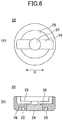
- Fig. 6 is a single item view illustrating the second shaft member 20 in which (A) is a top view and (B) is a sectional-view.
- the second shaft member 20 is cylindrical-shaped as a whole.
- the second shaft member 20 includes the magnetic flux generating part 24 and the body part 26, and the body part 26 has the guide channel 22 formed therein on the lower side.
- the upper side of the body part 26 has a concave portion 29 formed therein into which the lower part of the first shaft member 10 is inserted.
- the concave portion 29 is formed such that the lower part of the first shaft member 10 can move in X direction to permit a relative movement between the key channel 28 and the key 18 described hereinafter.
- the upper side of the body part 26 has the key channel 28 formed therein in which the key 18 of the first shaft member 10 is inserted.
- the key channel 28 may be formed such that the depth of the key channel 28 is greater than that of the bottom surface of the concave portion 29.
- the key channel 28 extends in X direction (longitudinal in X direction).
- the length of the key channel 28 (the length in X direction) is set to be substantially greater than that of the key 18 (in X direction). In other words, the key channel 28 and the key 18 are formed such that the relative movement in X direction is permitted.
- the width of the key channel 28 in Y direction may be substantially the same as the width of the key 18 in Y direction (i.e., there is no play between the key channel 28 and the key 18 in Y direction).
- the key channel 28 extends outwardly in the radius direction beyond the concave portion 29.
- the key channel 28 ends at a position that is inner in the radius direction with respect to the outline of the second shaft member 20; however, the key channel 28 may penetrate through the second shaft member 20 outwardly in the radius direction. In such a case, an inner peripheral surface of the lid member 50 may restrict the movement range of the key 18 in X direction.
- Fig. 7 is a top view explaining a decentering state of the input rotary shaft 90 in Y direction with respect to the center O of the rotation angle sensor 1, in which (A) illustrates a state in which there is no decentering in X and Y directions, (B) illustrates a decentering state to one side in Y direction, and (C) illustrates a decentering state to the other side in Y direction.
- Fig. 8 is a top view explaining a decentering state of the input rotary shaft 90 in X direction with respect to the center O of the rotation angle sensor 1, in which (A) illustrates a decentering state to one side in X direction, and (B) illustrates a decentering state to the other side in X direction. It is noted that, in Fig. 7 and Fig. 8 , for the sake of better understanding, the illustration of the lid member 50 is omitted.
- the input rotary shaft 90 is located at the center of the slot 14 of the first shaft member 10 of the input rotary shaft 90 in Y direction, as illustrated in Fig. 7 (A) .
- the key 18 of the first shaft member 10 comes to a position biased to one side in the key channel 28 of the second shaft member 20, as illustrated in Fig. 8 (A) .
- the first shaft member 10 and the second shaft member 20 form the Oldham's coupling such that the decentering of the input rotary shaft 90 with respect to the center O of the rotation angle sensor 1 to one side in X direction is permitted.
- the key 18 of the first shaft member 10 and the key channel 28 of the second shaft member 20 implement the integral rotation of the first shaft member 10 and the second shaft member 20 while permitting the shift in X direction between the first shaft member 10 and the second shaft member 20.
- the key 18 of the first shaft member 10 comes to a position biased to the other side in the key channel 28 of the second shaft member 20, as illustrated in Fig. 8 (B) .
- the first shaft member 10 and the second shaft member 20 form the Oldham's coupling such that the decentering of the input rotary shaft 90 with respect to the center O of the rotation angle sensor 1 to the other side in X direction is permitted.
- the input rotary shaft 90 may be decentered with respect to the center O of the rotation angle sensor 1 in X and Y directions.
- the decentering in X and Y directions is permitted due to a combination of the movements illustrated in Fig. 7 and Fig. 8 .
- the rotation angle sensor 1 it becomes possible for the rotation angle sensor 1 to include a mechanism for preventing the prying while permitting the decentering of the input rotary shaft 90 in X and Y directions.
- the first shaft member 10 and the second shaft member 20 it becomes possible to detect the rotation angle of the input rotary shaft 90 while preventing the prying even if the input rotary shaft 90 is decentered with respect to the center O of the rotation angle sensor 1 in an arbitrary direction in XY plane.
- the damage due to the decentering (damage due to the prying, etc.) can be reduced, which increases the durability of the rotation angle sensor 1.
- the first shaft member 10 and the second shaft member 20 are integrally formed, the prying occurs due to the decentering in X direction, which may cause the damage to the first shaft member 10 and the second shaft member 20.
- the first shaft member 10 and the second shaft member 20 are coupled such that the relative movement in X direction is permitted (via the key 18 and the key channel 28), which can reduce the probability of such damage.
- the first shaft member 10 includes the key 18 and the second shaft member 20 includes the key channel 28; however, this may be reversed.
- the first shaft member 10 may include a key channel and the second shaft member 20 may include a key.
- the second shaft member 20 includes the guide channel 22 and the rotation guide member 30 includes the protrusion 32; however, this may be reversed.
- the second shaft member 20 may include a protrusion and the rotation guide member 30 may include a guide channel.
- the end portion of the first shaft member 10 is cut to have two faces; however, the end portion may be cut to have one face (D-cut).
- the slot 14 may also form the D-cut space.
- the slot 14 is formed to permit the movement (play) of the first shaft member 10 in Y direction, as described above.
- the cable 80 is integrated with the rotation angle sensor 1; however, the cable 80 may be attached to the rotation angle sensor 1 afterward.
- the rotation angle sensor 1 may have external terminals.
Landscapes
- Physics & Mathematics (AREA)
- General Physics & Mathematics (AREA)
- Transmission And Conversion Of Sensor Element Output (AREA)
Description
- The disclosure is related to a rotation angle sensor.
- A rotation detection apparatus is known (see
Patent Literature 1, for example) in which a magnetic flux generating member is provided such that the magnetic flux generating member rotates together with a main rotation axis due to a rotation of an object to be detected, and a detection signal according to the rotation of the object is output using a magnetoelectric device that detects magnitude of the magnetic flux that changes according to the rotation of the magnetic flux generating member. Another rotation angle sensor is known fromUS2012/0210816 . - [PTL 1] Japanese Laid-open Patent Publication No.
2004-264094 - According to the rotation detection apparatus described above, an input rotary shaft is directly inserted into the magnetic flux generating member to be held therein; however, there may be a case where a manufacturing error, etc., causes decentering of the input rotary shaft with respect to the rotation axis of the magnetic flux generating member. In such a case, when a shift between the rotation axis of the magnetic flux generating member and a sensor center is rectified, prying occurs, which may easily cause damage of the magnetic flux generating member and thus reduce durability of the magnetic flux generating member. On the other hand, if the shift between the rotation axis of the magnetic flux generating member and a sensor center is not rectified, which can prevent the damage of the magnetic flux generating member, the shift causes a reduced detection accuracy of the rotation angle.
- Accordingly, it is an object of the disclosed technique to provide a rotation angle sensor that enables reducing prying due to a decentering of an input rotary shaft, while ensuring high detection accuracy of a rotation angle.
- According to one aspect of the disclosure, a rotation angle sensor is provided, which includes:
- a first shaft member that holds an input rotary shaft with play in a first direction to rotate with the input rotary shaft, the first direction being perpendicular to the input rotary shaft;
- a second shaft member that generates magnetic flux and holds the first shaft member with play in a second direction to rotate with the first shaft member, the second direction being perpendicular to the input rotary shaft and the first direction;
- a rotation guide member that rotatably supports the second shaft member and defines a rotation center of the second shaft member; and
- a detection element that is opposed to the second shaft member via the rotation guide member to detect the magnetic flux that changes according to a rotation angle of the second shaft member.
- According to the disclosed technique, a rotation angle sensor can be obtained that enables reducing prying due to a decentering of an input rotary shaft, while ensuring high detection accuracy of a rotation angle.
-
- [
Fig. 1 ]
Fig. 1 is a exploded perspective view of arotation angle sensor 1 according to an embodiment. - [
Fig.2 ]
Fig. 2 is a cross-sectional view of therotation angle sensor 1. - [
Fig.3 ]
Fig. 3 is a cross-sectional view of therotation angle sensor 1. - [
Fig.4 ]
Fig. 4 is a diagram explaining a center O of therotation angle sensor 1. - [
Fig.5 ]
Fig. 5 is a single item view illustrating afirst shaft member 10. - [
Fig.6 ]
Fig. 6 is a single item view illustrating asecond shaft member 20. - [
Fig.7 ]
Fig. 7 is a top view explaining a decentering state of an inputrotary shaft 90 in Y direction with respect to the center O of therotation angle sensor 1. - [
Fig.8 ]
Fig. 8 is a top view explaining a decentering state of an inputrotary shaft 90 in X direction with respect to the center O of therotation angle sensor 1. - In the following, embodiments are described in detail with reference to appended drawings.
-
Fig. 1 is a exploded perspective view of arotation angle sensor 1 according to an embodiment.Fig. 2 is a cross-sectional view of therotation angle sensor 1.Fig. 3 is a cross-sectional view of therotation angle sensor 1.Fig. 4 is a diagram explaining a center O (i.e., a detection axis) of therotation angle sensor 1, in which (A) is top view illustrating an example of adetection element 40, and (B) illustrates a relationship between the center O of therotation angle sensor 1 and a center O' of a magneticflux generating part 24. It is noted that, inFig. 1 , an example of an inputrotary shaft 90 is illustrated together with therotation angle sensor 1. In the following, an axial direction corresponds to a direction in which the inputrotary shaft 90 extends. Further, Y direction and X direction are perpendicular to the axial direction, and are perpendicular to each other. Further, therotation angle sensor 1 may be mounted in an arbitrary orientation; however, in the following, for the sake of convenience, it is assumed that an "upper side" corresponds to an upper side of the axial direction inFig. 2 . It is noted that in the present specification, "play" means play in a mechanism, and "play" is different from a clearance for a design tolerance, a manufacturing tolerance, etc. - The
rotation angle sensor 1 detects a rotation angle (i.e., a rotation position) of the inputrotary shaft 90. The inputrotary shaft 90 may be any one of rotation members in a vehicle (including a car, a two-wheeled vehicle, construction equipment, etc.). For example, the inputrotary shaft 90 may be a rotation axis of a drive mechanism (a transmission, for example), or a rotation axis of a steering mechanism (a steering shaft, for example). - As illustrated in
Fig. 1 , therotation angle sensor 1 includes afirst shaft member 10, asecond shaft member 20, arotation guide member 30, adetection element 40, and alid member 50. - The
first shaft member 10 may be formed of a resin. Thefirst shaft member 10 includes a slot 14 (longer in Y direction) into which the inputrotary shaft 90 is inserted. Thefirst shaft member 10 holds the inputrotary shaft 90 to rotate with the inputrotary shaft 90. Thefirst shaft member 10 holds the inputrotary shaft 90 such that the inputrotary shaft 90 has play in Y direction. In other words, a dimension of theslot 14 in Y direction is substantially longer than a length of an end of the inputrotary shaft 90 in Y direction. With this arrangement, the inputrotary shaft 90 can move in Y direction while the rotation thereof with respect tofirst shaft member 10 is restrained. It is noted that a range of the movement in Y direction is arbitrary, and may correspond to a range of a possible shift (decentering) amount of the inputrotary shaft 90 with respect to the center O of therotation angle sensor 1 in Y direction due to the manufacturing tolerance, etc. An example of a construction of thefirst shaft member 10 is described hereinafter. - The
second shaft member 20 may be formed of a resin. Thesecond shaft member 20 is provided such that thefirst shaft member 10 is seated on an upper surface of thesecond shaft member 20 in the axial direction, and a lower surface of thesecond shaft member 20 is seated on therotation guide member 30. Thesecond shaft member 20 holds thefirst shaft member 10 to rotate with thefirst shaft member 10. Thesecond shaft member 20 holds thefirst shaft member 10 such that thefirst shaft member 10 has play in X direction. In other words, thefirst shaft member 10 can move in X direction while the rotation thereof with respect to thesecond shaft member 20 is restrained. It is noted that a range of the movement in X direction is arbitrary, and may correspond to a range of a possible shift (decentering) amount of theinput rotary shaft 90 with respect to the center O of therotation angle sensor 1 in X direction due to the manufacturing tolerance, etc. - The
second shaft member 20 includes a magneticflux generating part 24 and abody part 26. - The magnetic
flux generating part 24 is provided to be concentric with the center O of therotation angle sensor 1, and may be a circular part that is concentric with the center O of therotation angle sensor 1, as illustrated inFig. 2 . For example, the magneticflux generating part 24 may be equally parted in a diameter direction viewed from top such that the parted portions form a south pole and a north pole, respectively (seeFig. 4 (B) ). The magneticflux generating part 24 may be a magnet embedded in thebody part 26 of thesecond shaft member 20. However, preferably, the magneticflux generating part 24 may be integrally formed with thebody part 26 using a resin material including magnetic particles (neodymium-based magnetic particles, for example). Thebody part 26 surrounds the magneticflux generating part 24. An example of construction of thesecond shaft member 20 is described hereinafter. - The
rotation guide member 30 may be formed of a resin. Therotation guide member 30 rotatably supports thesecond shaft member 20. Therotation guide member 30 guides the rotation of thesecond shaft member 20 to define the rotation center of thesecond shaft member 20. According to the invention, this guide mechanism is based on an engagement between aguide channel 22 and aprotrusion 32, as illustrated inFig. 1 , etc., for example. Specifically, a surface of therotation guide member 30 on a side on which thesecond shaft member 20 is seated has theprotrusion 32, as illustrated inFig. 1 . Theprotrusion 32 has a circular form viewed along the axial direction. Further, a surface of thesecond shaft member 20 on a side that is seated on therotation guide member 30 has theguide channel 22 formed therein in a circular form viewed along the axial direction. Thesecond shaft member 20 is provided on therotation guide member 30 such that theprotrusion 32 of therotation guide member 30 is engaged in theguide channel 22 of thesecond shaft member 20. With this arrangement, thesecond shaft member 20 can rotate and slide on therotation guide member 30 such that theprotrusion 32 is guided in theguide channel 22. At that time, a center of the rotation of thesecond shaft member 20 corresponds to a center of the circular shape of theguide channel 22. The circular shape of theguide channel 22 is set to have its center at the center O of therotation angle sensor 1. With this arrangement, during the rotation of thesecond shaft member 20, a state in which a rotation center of the second shaft member 20 (i.e., the rotation center of the magnetic flux generating part 24) is aligned with the center O of therotation angle sensor 1 is kept (seeFig. 4 (B) ). According to the invention, theprotrusion 32 has a clearance in theguide channel 22 such that thesecond shaft member 20 can smoothly rotate with respect to therotation guide member 30. Further, in order to reduce the sliding resistance or increase the durability for the sliding, therotation guide member 30 and/or thesecond shaft member 20 may be formed of a resin material in which polytetrafluoroethylene (PTFE) is compounded. Alternatively, from the same view point, therotation guide member 30 and/or thesecond shaft member 20 may have sliding surfaces coated. - It is noted that, in the example illustrated in
Fig. 1 , etc., the guide mechanism based on the engagement between theguide channel 22 and theprotrusion 32 is used; however, other guide mechanisms may be used. For example, theguide channel 22 may be a cylindrical column-shaped channel (concave portion) obtained by cutting away an inner portion in a radius direction. In this case, theprotrusion 32 may be a cylindrical column-shaped protrusion that is engaged in the cylindrically shaped channel. - The
detection element 40 is opposed to the magneticflux generating part 24 of thesecond shaft member 20 via therotation guide member 30 to detect the magnetic flux according to the rotation angle of thesecond shaft member 20. Thus, the rotation angle of the second shaft member 20 (and thus the rotation angle of the input rotary shaft 90) is detected. The detection axis of the detection element 40 (i.e., a center of a rotation detection) defines the center O of therotation angle sensor 1, as illustrated inFig. 4 (A) . In the example illustrated inFig. 4 (A) , the detection axis of thedetection element 40 corresponds to an original position O of a coordinate system defined by x and y axes. It is noted that the detection axis of thedetection element 40 is a point at which the detection accuracy (sensitivity) becomes the best when the center 0' of the magnet (seeFig. 4 (B) ) is aligned therewith, and the detection axis of thedetection element 40 does not necessarily correspond to a physical center of thedetection element 40. It is noted that the center O' of the magnet corresponds to the rotation center of the magneticflux generating part 24. Thedetection element 40 may be a Hall element, a MR (Magneto Resistance) element (magneto-resistance effect element), etc. Thedetection element 40 may be in a chip form as illustrated inFig. 4 , and may be installed on asubstrate 42 as illustrated inFig. 2 . An electrical signal from thedetection element 40 may be input to an external apparatus (an on-vehicle ECU (Electronic Control Unit), for example) via a communication line in acable 80. - It is noted that, in the example illustrated in
Fig. 2 , therotation guide member 30 has aninternal space 30a and thedetection element 40 installed on thesubstrate 42 is disposed in theinternal space 30a. Theinternal space 30a may be filled with a resin (epoxy resin, for example). - The
lid member 50 is cylindrical-shaped, as illustrated inFig. 1 , etc., and may be formed of a resin. Thelid member 50 is secured to therotation guide member 30. For example, thelid member 50 may be secured to therotation guide member 30 with adhesive, welding, etc. Thelid member 50 accommodates thefirst shaft member 10 and thesecond shaft member 20 therein. Thelid member 50 has an upper portion with an opening such that theslot 14 of thefirst shaft member 10 is exposed as a whole viewed from top. Thelid member 50 comes in contact with the upper surface of thefirst shaft member 10 in the axial direction to restrain displacements of thefirst shaft member 10 and thesecond shaft member 20 with respect to therotation guide member 30. In other words, thelid member 50 restrains the movement of thefirst shaft member 10 and thesecond shaft member 20 in the axial direction while permitting the rotation of thefirst shaft member 10 and thesecond shaft member 20. Thus, the engagement between thefirst shaft member 10 and the second shaft member 20 (i.e., the engagement between a key 18 and akey channel 28 described hereinafter) is maintained, and the engagement between thesecond shaft member 20 and the rotation guide member 30 (i.e., the engagement between theguide channel 22 and the protrusion 32) is maintained. - It is noted that, in the example illustrated in
Fig. 2 , thelid member 50 comes in contact with theupper surfaces first shaft member 10 and thesecond shaft member 20 in the axial direction, respectively, to directly restrain the movements of thefirst shaft member 10 and thesecond shaft member 20 in the axial direction. Further, in the example illustrated inFig. 2 , thelid member 50 also comes in contact with the key 18 (described hereinafter) in the axial direction. It is noted that, the contact manner described above is an example. For example, thelid member 50 may not come in direct contact with thesecond shaft member 20. In this case, thelid member 50 may come in contact with thefirst shaft member 10 to indirectly constrain the movement of thesecond shaft member 20 in the axial direction. -
Fig. 5 is a single item view illustrating thefirst shaft member 10, in which (A) is a top view, (B) is a sectional-view, (C) is a bottom view, and (D) is a side view. - The
first shaft member 10 is cylindrical-shaped as a whole. Thefirst shaft member 10 includes theslot 14 into which theinput rotary shaft 90 is inserted, as described above. Theslot 14 has a shape corresponding to the end portion of theinput rotary shaft 90, and is substantially longer than the end portion of theinput rotary shaft 90 in Y direction, as described above. The width of theslot 14 in X distance may be substantially the same as the width of theinput rotary shaft 90 in X direction (i.e., there is no play between theslot 14 and theinput rotary shaft 90 in X direction). In the example illustrated inFig. 1 , the end portion of theinput rotary shaft 90 is cut to have two faces (obtained by cutting a cylindrical column with two parallel faces), and accordingly theslot 14 is formed to have a substantially rectangular shape. More specifically, theslot 14 defines a cylindrical column space with a predetermined radius R1 that has twofaces faces faces faces input rotary shaft 90 by an amount of necessary play, for example. It is noted that theface 14b includes aconcave surface 14c; however, such aconcave surface 14c may be omitted. Theconcave surface 14c is provided for aconvex surface 90a of theinput rotary shaft 90 to define the insertion orientation of theinput rotary shaft 90. - It is noted that, in the example illustrated in
Fig. 5 , theslot 14 is a penetrating hole through thefirst shaft member 10 in the axial direction; however, theslot 14 may be a non-penetrating hole with a bottom. It is noted that, in the case where theslot 14 is a penetrating hole, theinput rotary shaft 90 passes through theslot 14 to have a tip end surface be in contact with the upper surface of aconcave portion 29 of thesecond shaft member 20. Again, in this case, the rotation of theinput rotary shaft 90 is transmitted to thesecond shaft member 20 not directly but via thefirst shaft member 10. - The
first shaft member 10 includes a key 18 on its lower side, as illustrated inFig. 5 . The key 18 extends in X direction (longitudinal in X direction). The length of the key 18 (the length in X direction) is arbitrary, but is set such that thefirst shaft member 10 and thesecond shaft member 20 can function as an Oldham's coupling described hereinafter. In the example illustrated inFig. 5 , the key 18 is formed such that the key 18 protrudes outwardly in the radius direction beyond an outline of the upper portion of thefirst shaft member 10. -
Fig. 6 is a single item view illustrating thesecond shaft member 20 in which (A) is a top view and (B) is a sectional-view. - The
second shaft member 20 is cylindrical-shaped as a whole. Thesecond shaft member 20 includes the magneticflux generating part 24 and thebody part 26, and thebody part 26 has theguide channel 22 formed therein on the lower side. The upper side of thebody part 26 has aconcave portion 29 formed therein into which the lower part of thefirst shaft member 10 is inserted. Theconcave portion 29 is formed such that the lower part of thefirst shaft member 10 can move in X direction to permit a relative movement between thekey channel 28 and the key 18 described hereinafter. - Further, the upper side of the
body part 26 has thekey channel 28 formed therein in which the key 18 of thefirst shaft member 10 is inserted. Thekey channel 28 may be formed such that the depth of thekey channel 28 is greater than that of the bottom surface of theconcave portion 29. Thekey channel 28 extends in X direction (longitudinal in X direction). The length of the key channel 28 (the length in X direction) is set to be substantially greater than that of the key 18 (in X direction). In other words, thekey channel 28 and the key 18 are formed such that the relative movement in X direction is permitted. The width of thekey channel 28 in Y direction may be substantially the same as the width of the key 18 in Y direction (i.e., there is no play between thekey channel 28 and the key 18 in Y direction). In the example illustrated inFig. 6 , thekey channel 28 extends outwardly in the radius direction beyond theconcave portion 29. Further, in the example illustrated inFig. 6 , thekey channel 28 ends at a position that is inner in the radius direction with respect to the outline of thesecond shaft member 20; however, thekey channel 28 may penetrate through thesecond shaft member 20 outwardly in the radius direction. In such a case, an inner peripheral surface of thelid member 50 may restrict the movement range of the key 18 in X direction. -
Fig. 7 is a top view explaining a decentering state of theinput rotary shaft 90 in Y direction with respect to the center O of therotation angle sensor 1, in which (A) illustrates a state in which there is no decentering in X and Y directions, (B) illustrates a decentering state to one side in Y direction, and (C) illustrates a decentering state to the other side in Y direction.Fig. 8 is a top view explaining a decentering state of theinput rotary shaft 90 in X direction with respect to the center O of therotation angle sensor 1, in which (A) illustrates a decentering state to one side in X direction, and (B) illustrates a decentering state to the other side in X direction. It is noted that, inFig. 7 andFig. 8 , for the sake of better understanding, the illustration of thelid member 50 is omitted. - In a state in which there is no decentering of the
input rotary shaft 90 in X and Y directions with respect to the center O of therotation angle sensor 1, theinput rotary shaft 90 is located at the center of theslot 14 of thefirst shaft member 10 of theinput rotary shaft 90 in Y direction, as illustrated inFig. 7 (A) . - When the
input rotary shaft 90 is decentered with respect to the center O of therotation angle sensor 1 to one side in Y direction, theinput rotary shaft 90 comes to a position biased to one side in theslot 14 of thefirst shaft member 10 of theinput rotary shaft 90, as illustrated inFig. 7 (B) . Thus, the prying due to such a decentering (i.e., the prying due to theinput rotary shaft 90 in theslot 14 of the first shaft member 10) can be prevented. It is noted that, in this state, if theinput rotary shaft 90 is not decentered with respect to the center O of therotation angle sensor 1 in X direction, the key 18 of thefirst shaft member 10 is located at the center of thekey channel 28 of thesecond shaft member 20 in X direction. - Similarly, when the
input rotary shaft 90 is decentered with respect to the center O of therotation angle sensor 1 to the other side in Y direction, theinput rotary shaft 90 comes to a position biased to the other side in theslot 14 of thefirst shaft member 10 of theinput rotary shaft 90, as illustrated inFig. 7 (C) . Thus, the prying due to such a decentering (i.e., the prying due to theinput rotary shaft 90 in theslot 14 of the first shaft member 10) can be prevented. It is noted that, in this state, if theinput rotary shaft 90 is not decentered with respect to the center O of therotation angle sensor 1 in X direction, the key 18 of thefirst shaft member 10 is located at the center of thekey channel 28 of thesecond shaft member 20 in X direction. - Further, when the
input rotary shaft 90 is decentered with respect to the center O of therotation angle sensor 1 to one side in X direction, the key 18 of thefirst shaft member 10 comes to a position biased to one side in thekey channel 28 of thesecond shaft member 20, as illustrated inFig. 8 (A) . In this way, thefirst shaft member 10 and thesecond shaft member 20 form the Oldham's coupling such that the decentering of theinput rotary shaft 90 with respect to the center O of therotation angle sensor 1 to one side in X direction is permitted. In other words, the key 18 of thefirst shaft member 10 and thekey channel 28 of thesecond shaft member 20 implement the integral rotation of thefirst shaft member 10 and thesecond shaft member 20 while permitting the shift in X direction between thefirst shaft member 10 and thesecond shaft member 20. It is noted that, in such a state, if theinput rotary shaft 90 is not decentered with respect to the center O of therotation angle sensor 1 in Y direction, theinput rotary shaft 90 is located at the center of theslot 14 of thefirst shaft member 10 in Y direction. - Similarly, when the
input rotary shaft 90 is decentered with respect to the center O of therotation angle sensor 1 to the other side in X direction, the key 18 of thefirst shaft member 10 comes to a position biased to the other side in thekey channel 28 of thesecond shaft member 20, as illustrated inFig. 8 (B) . In this way, thefirst shaft member 10 and thesecond shaft member 20 form the Oldham's coupling such that the decentering of theinput rotary shaft 90 with respect to the center O of therotation angle sensor 1 to the other side in X direction is permitted. It is noted that, in such a state, if theinput rotary shaft 90 is not decentered with respect to the center O of therotation angle sensor 1 in Y direction, theinput rotary shaft 90 is located at the center of theslot 14 of thefirst shaft member 10 in Y direction. - It is noted that, in practice, the
input rotary shaft 90 may be decentered with respect to the center O of therotation angle sensor 1 in X and Y directions. In this case, the decentering in X and Y directions is permitted due to a combination of the movements illustrated inFig. 7 andFig. 8 . In this way, it becomes possible for therotation angle sensor 1 to include a mechanism for preventing the prying while permitting the decentering of theinput rotary shaft 90 in X and Y directions. - According to the
rotation angle sensor 1 of this embodiment, the following effect among others can be obtained. - As described above, by providing the
first shaft member 10 and thesecond shaft member 20, it becomes possible to detect the rotation angle of theinput rotary shaft 90 while preventing the prying even if theinput rotary shaft 90 is decentered with respect to the center O of therotation angle sensor 1 in an arbitrary direction in XY plane. Thus, the damage due to the decentering (damage due to the prying, etc.) can be reduced, which increases the durability of therotation angle sensor 1. For example, if thefirst shaft member 10 and thesecond shaft member 20 are integrally formed, the prying occurs due to the decentering in X direction, which may cause the damage to thefirst shaft member 10 and thesecond shaft member 20. In contrast, according to the embodiment, thefirst shaft member 10 and thesecond shaft member 20 are coupled such that the relative movement in X direction is permitted (via the key 18 and the key channel 28), which can reduce the probability of such damage. - Further, according to the embodiment, even when the
input rotary shaft 90 is decentered with respect to the center O of therotation angle sensor 1 in any direction in XY plane, a state in which the rotation center of the second shaft member 20 (i.e., the rotation center of the magnetic flux generating part 24) is aligned with the center O of therotation angle sensor 1 is kept. Specifically, due to the guide mechanism between therotation guide member 30 and thesecond shaft member 20, state in which the rotation center of thesecond shaft member 20 is aligned with the center O of therotation angle sensor 1 is kept. Thus, even if theinput rotary shaft 90 is decentered with respect to the center O of therotation angle sensor 1 in any direction in XY plane, it becomes possible to keep high detection accuracy of therotation angle sensor 1. - All examples and conditional language recited herein are intended for pedagogical purposes to aid the reader in understanding the invention and the concepts contributed by the inventor to furthering the art, and are to be construed as being without limitation to such specifically recited examples and conditions, nor does the organization of such examples in the specification relate to a showing of the superiority and inferiority of the invention. Although the embodiment(s) of the present inventions have been described in detail, it should be understood that the various changes, substitutions, and alterations could be made hereto without departing from the spirit and scope of the invention. Further, all or part of the components of the embodiments described above can be combined.
- For example, according to the embodiment, the
first shaft member 10 includes the key 18 and thesecond shaft member 20 includes thekey channel 28; however, this may be reversed. Specifically, thefirst shaft member 10 may include a key channel and thesecond shaft member 20 may include a key. - Further, in the embodiment described above, the
second shaft member 20 includes theguide channel 22 and therotation guide member 30 includes theprotrusion 32; however, this may be reversed. Specifically, thesecond shaft member 20 may include a protrusion and therotation guide member 30 may include a guide channel. - Further, in the embodiment described above, the end portion of the
first shaft member 10 is cut to have two faces; however, the end portion may be cut to have one face (D-cut). In this case, theslot 14 may also form the D-cut space. However, theslot 14 is formed to permit the movement (play) of thefirst shaft member 10 in Y direction, as described above. - Further, in the embodiment described above, the
cable 80 is integrated with therotation angle sensor 1; however, thecable 80 may be attached to therotation angle sensor 1 afterward. In other words, therotation angle sensor 1 may have external terminals. -
- 1
- rotation angle sensor
- 10
- first shaft member
- 14
- slot
- 18
- key
- 20
- second shaft member
- 22
- guide channel
- 24
- magnetic flux generating part
- 26
- body part
- 28
- key channel
- 30
- rotation guide member
- 32
- protrusion
- 40
- detection element
- 42
- substrate
- 50
- lid member
- 90
- input rotary shaft
Claims (7)
- A rotation angle sensor (1), comprising:a first shaft member (10) that holds an input rotary shaft (90) with play in a first direction (Y) to rotate with the input rotary shaft (90), the first direction (Y) being perpendicular to the input rotary shaft (90);a second shaft member (20) that generates magnetic flux and holds the first shaft member (10) with play in a second direction (X) to rotate with the first shaft member (10), the second direction (X) being perpendicular to the input rotary shaft (90) and the first direction (Y);a rotation guide member (30) that rotatably supports the second shaft member (20) and defines a rotation center of the second shaft member (20); anda detection element (40) that is opposed to the second shaft member (20) via the rotation guide member (30) to detect the magnetic flux that changes according to a rotation angle of the second shaft member (20);wherein one of the second shaft member (20) and the rotation guide member (30) has a contact surface having a guide channel (22) formed therein in a circular form viewed along an axial direction, and the other of the second shaft member (20) and the rotation guide member (30) having a contact surface with a protrusion (32) formed therein in a circular form viewed along the axial direction, the contact surfaces of the second shaft member (20) and the rotation guide member (30) being in contact with each other, the protrusion (32) being engaged with the guide channel (22) with a clearance therebetween.
- The rotation angle sensor of claim 1, wherein the rotation guide member guides the rotation of the second shaft member such that the rotation center of the second shaft member corresponds to a detection axis of the detection element.
- The rotation angle sensor of any one of claim 1 or claim 2, wherein the first shaft member and the second shaft member form an Oldham's coupling.
- The rotation angle sensor of any one of claims 1 to 3, further comprising a lid member that is secured to the rotation guide member and accommodates the first shaft member and the second shaft member therein to restrain displacements of the first shaft member and the second shaft member in the axial direction with respect to the rotation guide member.
- The rotation angle sensor of any one of claims 1 to 4, wherein the first shaft member includes a slot into which an end of the input rotary shaft is inserted, the end being cut to have two faces.
- The rotation angle sensor of any one of claims 1 to 5, wherein the second shaft member includes a magnetic flux generating part and a body part that are integrally formed, the magnetic flux generating part generating the magnetic flux.
- The rotation angle sensor of claim 1, wherein the circular form has a center at a position corresponding to the detection axis of the detection element.
Applications Claiming Priority (1)
| Application Number | Priority Date | Filing Date | Title |
|---|---|---|---|
| PCT/JP2013/076496 WO2015045140A1 (en) | 2013-09-30 | 2013-09-30 | Rotation angle sensor |
Publications (3)
| Publication Number | Publication Date |
|---|---|
| EP3054269A1 EP3054269A1 (en) | 2016-08-10 |
| EP3054269A4 EP3054269A4 (en) | 2016-09-14 |
| EP3054269B1 true EP3054269B1 (en) | 2018-01-17 |
Family
ID=52742339
Family Applications (1)
| Application Number | Title | Priority Date | Filing Date |
|---|---|---|---|
| EP13894902.9A Active EP3054269B1 (en) | 2013-09-30 | 2013-09-30 | Rotation angle sensor |
Country Status (3)
| Country | Link |
|---|---|
| EP (1) | EP3054269B1 (en) |
| JP (1) | JP6122964B2 (en) |
| WO (1) | WO2015045140A1 (en) |
Family Cites Families (6)
| Publication number | Priority date | Publication date | Assignee | Title |
|---|---|---|---|---|
| JPH076721U (en) * | 1993-06-30 | 1995-01-31 | エヌティエヌ株式会社 | Rotation angle detector |
| JP3829331B2 (en) | 2003-02-28 | 2006-10-04 | 日本精機株式会社 | Angle detector |
| JP4558459B2 (en) * | 2004-11-25 | 2010-10-06 | 株式会社小松製作所 | Radial piston type fluid rotary machine |
| JP4512128B2 (en) * | 2007-10-25 | 2010-07-28 | 本田技研工業株式会社 | Motor rotation angle detection device |
| JP5488494B2 (en) * | 2011-02-23 | 2014-05-14 | 株式会社安川電機 | Robot system |
| JP2013113785A (en) * | 2011-11-30 | 2013-06-10 | Nippon Seiki Co Ltd | Rotation angle detection device |
-
2013
- 2013-09-30 WO PCT/JP2013/076496 patent/WO2015045140A1/en not_active Ceased
- 2013-09-30 JP JP2015538773A patent/JP6122964B2/en active Active
- 2013-09-30 EP EP13894902.9A patent/EP3054269B1/en active Active
Non-Patent Citations (1)
| Title |
|---|
| None * |
Also Published As
| Publication number | Publication date |
|---|---|
| JP6122964B2 (en) | 2017-04-26 |
| JPWO2015045140A1 (en) | 2017-03-02 |
| EP3054269A1 (en) | 2016-08-10 |
| WO2015045140A1 (en) | 2015-04-02 |
| EP3054269A4 (en) | 2016-09-14 |
Similar Documents
| Publication | Publication Date | Title |
|---|---|---|
| JP6947236B2 (en) | Detection device | |
| US9784595B2 (en) | Magnetic linear or rotary encoder | |
| CN111819739B (en) | Rotary connector device and assembling structure of rotary connector device | |
| US11906300B2 (en) | Absolute encoder | |
| EP3023744A1 (en) | Rotation angle detecting device | |
| WO2014112004A1 (en) | Liquid level detection device | |
| EP3054269A1 (en) | Rotation angle sensor | |
| JP5436459B2 (en) | Accelerator device | |
| US20220364884A1 (en) | Steering apparatus | |
| JP2013113785A (en) | Rotation angle detection device | |
| US20220170731A1 (en) | Absolute encoder | |
| CN108474668B (en) | position detection device | |
| JP5678865B2 (en) | Mounting structure of liquid level detector | |
| CN113631892A (en) | Absolute encoder | |
| CN114867993A (en) | Absolute encoder | |
| US10383240B2 (en) | Housing to retain integrated circuit package | |
| JP2016057099A (en) | Liquid level detector | |
| JP5848953B2 (en) | Shift lever device | |
| JP4862788B2 (en) | Rotation detector | |
| JP4460048B2 (en) | Magnetic encoder | |
| JP2019052992A (en) | Rotation angle detection device | |
| JP2007256121A (en) | Electronic rotation angle measurement unit | |
| JP2018146292A (en) | Position detection device | |
| JP2006177924A (en) | Displacement detector | |
| JP2013228208A (en) | Moving object detector and manufacturing method of the same |
Legal Events
| Date | Code | Title | Description |
|---|---|---|---|
| PUAI | Public reference made under article 153(3) epc to a published international application that has entered the european phase |
Free format text: ORIGINAL CODE: 0009012 |
|
| REG | Reference to a national code |
Ref country code: DE Ref legal event code: R079 Ref document number: 602013032446 Country of ref document: DE Free format text: PREVIOUS MAIN CLASS: G01D0005120000 Ipc: G01D0005140000 |
|
| 17P | Request for examination filed |
Effective date: 20160219 |
|
| AK | Designated contracting states |
Kind code of ref document: A1 Designated state(s): AL AT BE BG CH CY CZ DE DK EE ES FI FR GB GR HR HU IE IS IT LI LT LU LV MC MK MT NL NO PL PT RO RS SE SI SK SM TR |
|
| AX | Request for extension of the european patent |
Extension state: BA ME |
|
| A4 | Supplementary search report drawn up and despatched |
Effective date: 20160817 |
|
| RIC1 | Information provided on ipc code assigned before grant |
Ipc: G01D 5/14 20060101AFI20160809BHEP |
|
| DAX | Request for extension of the european patent (deleted) | ||
| STAA | Information on the status of an ep patent application or granted ep patent |
Free format text: STATUS: EXAMINATION IS IN PROGRESS |
|
| 17Q | First examination report despatched |
Effective date: 20170216 |
|
| GRAP | Despatch of communication of intention to grant a patent |
Free format text: ORIGINAL CODE: EPIDOSNIGR1 |
|
| STAA | Information on the status of an ep patent application or granted ep patent |
Free format text: STATUS: GRANT OF PATENT IS INTENDED |
|
| INTG | Intention to grant announced |
Effective date: 20170802 |
|
| GRAS | Grant fee paid |
Free format text: ORIGINAL CODE: EPIDOSNIGR3 |
|
| GRAA | (expected) grant |
Free format text: ORIGINAL CODE: 0009210 |
|
| STAA | Information on the status of an ep patent application or granted ep patent |
Free format text: STATUS: THE PATENT HAS BEEN GRANTED |
|
| AK | Designated contracting states |
Kind code of ref document: B1 Designated state(s): AL AT BE BG CH CY CZ DE DK EE ES FI FR GB GR HR HU IE IS IT LI LT LU LV MC MK MT NL NO PL PT RO RS SE SI SK SM TR |
|
| RAP1 | Party data changed (applicant data changed or rights of an application transferred) |
Owner name: TRANSTRON INC. |
|
| REG | Reference to a national code |
Ref country code: GB Ref legal event code: FG4D |
|
| REG | Reference to a national code |
Ref country code: CH Ref legal event code: EP |
|
| REG | Reference to a national code |
Ref country code: IE Ref legal event code: FG4D |
|
| REG | Reference to a national code |
Ref country code: AT Ref legal event code: REF Ref document number: 964728 Country of ref document: AT Kind code of ref document: T Effective date: 20180215 |
|
| REG | Reference to a national code |
Ref country code: DE Ref legal event code: R096 Ref document number: 602013032446 Country of ref document: DE |
|
| REG | Reference to a national code |
Ref country code: NL Ref legal event code: MP Effective date: 20180117 |
|
| REG | Reference to a national code |
Ref country code: LT Ref legal event code: MG4D |
|
| REG | Reference to a national code |
Ref country code: AT Ref legal event code: MK05 Ref document number: 964728 Country of ref document: AT Kind code of ref document: T Effective date: 20180117 |
|
| PG25 | Lapsed in a contracting state [announced via postgrant information from national office to epo] |
Ref country code: NL Free format text: LAPSE BECAUSE OF FAILURE TO SUBMIT A TRANSLATION OF THE DESCRIPTION OR TO PAY THE FEE WITHIN THE PRESCRIBED TIME-LIMIT Effective date: 20180117 |
|
| PG25 | Lapsed in a contracting state [announced via postgrant information from national office to epo] |
Ref country code: ES Free format text: LAPSE BECAUSE OF FAILURE TO SUBMIT A TRANSLATION OF THE DESCRIPTION OR TO PAY THE FEE WITHIN THE PRESCRIBED TIME-LIMIT Effective date: 20180117 Ref country code: CY Free format text: LAPSE BECAUSE OF FAILURE TO SUBMIT A TRANSLATION OF THE DESCRIPTION OR TO PAY THE FEE WITHIN THE PRESCRIBED TIME-LIMIT Effective date: 20180117 Ref country code: FI Free format text: LAPSE BECAUSE OF FAILURE TO SUBMIT A TRANSLATION OF THE DESCRIPTION OR TO PAY THE FEE WITHIN THE PRESCRIBED TIME-LIMIT Effective date: 20180117 Ref country code: NO Free format text: LAPSE BECAUSE OF FAILURE TO SUBMIT A TRANSLATION OF THE DESCRIPTION OR TO PAY THE FEE WITHIN THE PRESCRIBED TIME-LIMIT Effective date: 20180417 Ref country code: HR Free format text: LAPSE BECAUSE OF FAILURE TO SUBMIT A TRANSLATION OF THE DESCRIPTION OR TO PAY THE FEE WITHIN THE PRESCRIBED TIME-LIMIT Effective date: 20180117 Ref country code: LT Free format text: LAPSE BECAUSE OF FAILURE TO SUBMIT A TRANSLATION OF THE DESCRIPTION OR TO PAY THE FEE WITHIN THE PRESCRIBED TIME-LIMIT Effective date: 20180117 |
|
| PG25 | Lapsed in a contracting state [announced via postgrant information from national office to epo] |
Ref country code: LV Free format text: LAPSE BECAUSE OF FAILURE TO SUBMIT A TRANSLATION OF THE DESCRIPTION OR TO PAY THE FEE WITHIN THE PRESCRIBED TIME-LIMIT Effective date: 20180117 Ref country code: SE Free format text: LAPSE BECAUSE OF FAILURE TO SUBMIT A TRANSLATION OF THE DESCRIPTION OR TO PAY THE FEE WITHIN THE PRESCRIBED TIME-LIMIT Effective date: 20180117 Ref country code: AT Free format text: LAPSE BECAUSE OF FAILURE TO SUBMIT A TRANSLATION OF THE DESCRIPTION OR TO PAY THE FEE WITHIN THE PRESCRIBED TIME-LIMIT Effective date: 20180117 Ref country code: BG Free format text: LAPSE BECAUSE OF FAILURE TO SUBMIT A TRANSLATION OF THE DESCRIPTION OR TO PAY THE FEE WITHIN THE PRESCRIBED TIME-LIMIT Effective date: 20180417 Ref country code: RS Free format text: LAPSE BECAUSE OF FAILURE TO SUBMIT A TRANSLATION OF THE DESCRIPTION OR TO PAY THE FEE WITHIN THE PRESCRIBED TIME-LIMIT Effective date: 20180117 Ref country code: GR Free format text: LAPSE BECAUSE OF FAILURE TO SUBMIT A TRANSLATION OF THE DESCRIPTION OR TO PAY THE FEE WITHIN THE PRESCRIBED TIME-LIMIT Effective date: 20180418 Ref country code: IS Free format text: LAPSE BECAUSE OF FAILURE TO SUBMIT A TRANSLATION OF THE DESCRIPTION OR TO PAY THE FEE WITHIN THE PRESCRIBED TIME-LIMIT Effective date: 20180517 Ref country code: PL Free format text: LAPSE BECAUSE OF FAILURE TO SUBMIT A TRANSLATION OF THE DESCRIPTION OR TO PAY THE FEE WITHIN THE PRESCRIBED TIME-LIMIT Effective date: 20180117 |
|
| REG | Reference to a national code |
Ref country code: DE Ref legal event code: R097 Ref document number: 602013032446 Country of ref document: DE |
|
| PG25 | Lapsed in a contracting state [announced via postgrant information from national office to epo] |
Ref country code: RO Free format text: LAPSE BECAUSE OF FAILURE TO SUBMIT A TRANSLATION OF THE DESCRIPTION OR TO PAY THE FEE WITHIN THE PRESCRIBED TIME-LIMIT Effective date: 20180117 Ref country code: EE Free format text: LAPSE BECAUSE OF FAILURE TO SUBMIT A TRANSLATION OF THE DESCRIPTION OR TO PAY THE FEE WITHIN THE PRESCRIBED TIME-LIMIT Effective date: 20180117 Ref country code: AL Free format text: LAPSE BECAUSE OF FAILURE TO SUBMIT A TRANSLATION OF THE DESCRIPTION OR TO PAY THE FEE WITHIN THE PRESCRIBED TIME-LIMIT Effective date: 20180117 |
|
| PLBE | No opposition filed within time limit |
Free format text: ORIGINAL CODE: 0009261 |
|
| STAA | Information on the status of an ep patent application or granted ep patent |
Free format text: STATUS: NO OPPOSITION FILED WITHIN TIME LIMIT |
|
| PG25 | Lapsed in a contracting state [announced via postgrant information from national office to epo] |
Ref country code: DK Free format text: LAPSE BECAUSE OF FAILURE TO SUBMIT A TRANSLATION OF THE DESCRIPTION OR TO PAY THE FEE WITHIN THE PRESCRIBED TIME-LIMIT Effective date: 20180117 Ref country code: SM Free format text: LAPSE BECAUSE OF FAILURE TO SUBMIT A TRANSLATION OF THE DESCRIPTION OR TO PAY THE FEE WITHIN THE PRESCRIBED TIME-LIMIT Effective date: 20180117 Ref country code: SK Free format text: LAPSE BECAUSE OF FAILURE TO SUBMIT A TRANSLATION OF THE DESCRIPTION OR TO PAY THE FEE WITHIN THE PRESCRIBED TIME-LIMIT Effective date: 20180117 Ref country code: CZ Free format text: LAPSE BECAUSE OF FAILURE TO SUBMIT A TRANSLATION OF THE DESCRIPTION OR TO PAY THE FEE WITHIN THE PRESCRIBED TIME-LIMIT Effective date: 20180117 |
|
| 26N | No opposition filed |
Effective date: 20181018 |
|
| PG25 | Lapsed in a contracting state [announced via postgrant information from national office to epo] |
Ref country code: SI Free format text: LAPSE BECAUSE OF FAILURE TO SUBMIT A TRANSLATION OF THE DESCRIPTION OR TO PAY THE FEE WITHIN THE PRESCRIBED TIME-LIMIT Effective date: 20180117 |
|
| PG25 | Lapsed in a contracting state [announced via postgrant information from national office to epo] |
Ref country code: MC Free format text: LAPSE BECAUSE OF FAILURE TO SUBMIT A TRANSLATION OF THE DESCRIPTION OR TO PAY THE FEE WITHIN THE PRESCRIBED TIME-LIMIT Effective date: 20180117 |
|
| REG | Reference to a national code |
Ref country code: CH Ref legal event code: PL |
|
| REG | Reference to a national code |
Ref country code: BE Ref legal event code: MM Effective date: 20180930 |
|
| REG | Reference to a national code |
Ref country code: IE Ref legal event code: MM4A |
|
| PG25 | Lapsed in a contracting state [announced via postgrant information from national office to epo] |
Ref country code: LU Free format text: LAPSE BECAUSE OF NON-PAYMENT OF DUE FEES Effective date: 20180930 |
|
| PG25 | Lapsed in a contracting state [announced via postgrant information from national office to epo] |
Ref country code: IE Free format text: LAPSE BECAUSE OF NON-PAYMENT OF DUE FEES Effective date: 20180930 |
|
| PG25 | Lapsed in a contracting state [announced via postgrant information from national office to epo] |
Ref country code: LI Free format text: LAPSE BECAUSE OF NON-PAYMENT OF DUE FEES Effective date: 20180930 Ref country code: CH Free format text: LAPSE BECAUSE OF NON-PAYMENT OF DUE FEES Effective date: 20180930 Ref country code: FR Free format text: LAPSE BECAUSE OF NON-PAYMENT OF DUE FEES Effective date: 20180930 Ref country code: BE Free format text: LAPSE BECAUSE OF NON-PAYMENT OF DUE FEES Effective date: 20180930 |
|
| PG25 | Lapsed in a contracting state [announced via postgrant information from national office to epo] |
Ref country code: MT Free format text: LAPSE BECAUSE OF NON-PAYMENT OF DUE FEES Effective date: 20180930 |
|
| PG25 | Lapsed in a contracting state [announced via postgrant information from national office to epo] |
Ref country code: TR Free format text: LAPSE BECAUSE OF FAILURE TO SUBMIT A TRANSLATION OF THE DESCRIPTION OR TO PAY THE FEE WITHIN THE PRESCRIBED TIME-LIMIT Effective date: 20180117 |
|
| PG25 | Lapsed in a contracting state [announced via postgrant information from national office to epo] |
Ref country code: PT Free format text: LAPSE BECAUSE OF FAILURE TO SUBMIT A TRANSLATION OF THE DESCRIPTION OR TO PAY THE FEE WITHIN THE PRESCRIBED TIME-LIMIT Effective date: 20180117 |
|
| PG25 | Lapsed in a contracting state [announced via postgrant information from national office to epo] |
Ref country code: MK Free format text: LAPSE BECAUSE OF NON-PAYMENT OF DUE FEES Effective date: 20180117 Ref country code: HU Free format text: LAPSE BECAUSE OF FAILURE TO SUBMIT A TRANSLATION OF THE DESCRIPTION OR TO PAY THE FEE WITHIN THE PRESCRIBED TIME-LIMIT; INVALID AB INITIO Effective date: 20130930 |
|
| REG | Reference to a national code |
Ref country code: DE Ref legal event code: R082 Ref document number: 602013032446 Country of ref document: DE Representative=s name: HL KEMPNER PATENTANWAELTE, SOLICITORS (ENGLAND, DE Ref country code: DE Ref legal event code: R082 Ref document number: 602013032446 Country of ref document: DE Representative=s name: HL KEMPNER PATENTANWALT, RECHTSANWALT, SOLICIT, DE Ref country code: DE Ref legal event code: R082 Ref document number: 602013032446 Country of ref document: DE Representative=s name: HL KEMPNER PARTG MBB, DE |
|
| PGFP | Annual fee paid to national office [announced via postgrant information from national office to epo] |
Ref country code: DE Payment date: 20250820 Year of fee payment: 13 |
|
| PGFP | Annual fee paid to national office [announced via postgrant information from national office to epo] |
Ref country code: IT Payment date: 20250820 Year of fee payment: 13 |
|
| PGFP | Annual fee paid to national office [announced via postgrant information from national office to epo] |
Ref country code: GB Payment date: 20250822 Year of fee payment: 13 |