EP3053770A1 - Work vehicle - Google Patents
Work vehicle Download PDFInfo
- Publication number
- EP3053770A1 EP3053770A1 EP14848714.3A EP14848714A EP3053770A1 EP 3053770 A1 EP3053770 A1 EP 3053770A1 EP 14848714 A EP14848714 A EP 14848714A EP 3053770 A1 EP3053770 A1 EP 3053770A1
- Authority
- EP
- European Patent Office
- Prior art keywords
- work vehicle
- connection member
- front axle
- power steering
- steering cylinder
- Prior art date
- Legal status (The legal status is an assumption and is not a legal conclusion. Google has not performed a legal analysis and makes no representation as to the accuracy of the status listed.)
- Granted
Links
Images




Classifications
-
- B—PERFORMING OPERATIONS; TRANSPORTING
- B62—LAND VEHICLES FOR TRAVELLING OTHERWISE THAN ON RAILS
- B62D—MOTOR VEHICLES; TRAILERS
- B62D5/00—Power-assisted or power-driven steering
- B62D5/06—Power-assisted or power-driven steering fluid, i.e. using a pressurised fluid for most or all the force required for steering a vehicle
- B62D5/10—Power-assisted or power-driven steering fluid, i.e. using a pressurised fluid for most or all the force required for steering a vehicle characterised by type of power unit
- B62D5/12—Piston and cylinder
-
- B—PERFORMING OPERATIONS; TRANSPORTING
- B62—LAND VEHICLES FOR TRAVELLING OTHERWISE THAN ON RAILS
- B62D—MOTOR VEHICLES; TRAILERS
- B62D7/00—Steering linkage; Stub axles or their mountings
- B62D7/06—Steering linkage; Stub axles or their mountings for individually-pivoted wheels, e.g. on king-pins
- B62D7/08—Steering linkage; Stub axles or their mountings for individually-pivoted wheels, e.g. on king-pins the pivotal axes being situated in a single plane transverse to the longitudinal centre line of the vehicle
- B62D7/10—Steering linkage; Stub axles or their mountings for individually-pivoted wheels, e.g. on king-pins the pivotal axes being situated in a single plane transverse to the longitudinal centre line of the vehicle with single-output steering gear
Definitions
- the present invention relates to a work vehicle in which a power steering cylinder is attached to a front axle casing.
- a power steering cylinder changing a steering angle of a pair of front wheels is provided.
- a main body of the power steering cylinder is attached to a front axle casing whose lengthwise direction is arranged along the transverse direction of the work vehicle.
- a rod of the power steering cylinder is attached to a knuckle arm or a transmission rod.
- a fixed side (main body) of the power steering cylinder is fixed via a ball joint to a support stay extended rearward from the front axle casing.
- a height position of the support stay or the like is adjusted so as to make the fixed part of the power steering cylinder within a range of vertical height of the front axle casing.
- connection member connecting the power steering cylinder is arranged behind the front axle casing so that the connection member is not projected downward from the front axle casing.
- the support stay may be arranged at the same height as a lower end of a front axle bracket.
- connection member such as the ball joint is arranged lower than the front axle casing. Accordingly, in this case, the connection member may contact the obstacle on the ground at traveling of the work vehicle.
- Patent Literature 1 the Japanese Patent Laid Open Gazette Hei. 10-7009
- the present invention is provided in consideration of the conditions as mentioned above, and the purpose of the invention is to provide a work vehicle in which a connection member can be prevented from contacting an obstacle at traveling of the work vehicle without any restriction of a layout of the work vehicle.
- a work vehicle in which a power steering cylinder is attached to a front axle casing is characterized in that the front axle casing is formed therein with a support part to which the power steering cylinder is attached by a connection member, and a protruding part protruding from the support part so as to cover the connection member when viewed from the front side of the work vehicle.
- the protruding part is formed in the support part so as to be curved or bent toward a front side of the work vehicle.
- a lower end of the protruding part is extended rearward when viewed in side.
- the present invention brings the following effects.
- connection member can be prevented from contacting an obstacle at traveling of the work vehicle without any restriction of the layout of the work vehicle.
- connection member can be prevented from contacting an obstacle at traveling of the work vehicle more certainly.
- connection member can be prevented from contacting an obstacle at traveling of the work vehicle more certainly.
- the work vehicle 1 of this embodiment is a tractor.
- an object to which the work vehicle according to the present invention is not limited to the tractor.
- a direction of an arrow F in Fig. 1 is regarded as the front direction so as to specify the longitudinal direction of the work vehicle 1.
- a direction of an arrow U in Fig. 1 is regarded as the upper direction so as to specify the vertical direction of the work vehicle 1.
- a direction of an arrow L in Fig. 1 is regarded as the left direction so as to specify the lateral direction of the work vehicle 1.
- a body frame 10 is arranged so that a lengthwise direction thereof is arranged along the longitudinal direction.
- the body frame 10 is configured by welding a front axle bracket 12 via a pair of reinforcement plates to a pair of beams 11 which are arranged at a predetermined interval while a lengthwise direction thereof is arranged along the longitudinal direction.
- a front part of the body frame 10 supports an engine 2 via an engine bracket.
- the engine 2 is covered by a bonnet 3 or the like.
- the front part of the body frame 10 is supported via a front axle casing 30 by a pair of front wheels 4.
- a rear part of the body frame 10 is supported via a transmission casing 60 and rear axle casings 61 by a pair of rear wheels 5.
- an operation part 6 is arranged in an upper part of the body frame 10.
- the operation part 6 has a steering wheel 6a, a seat 6b and the like.
- the steering wheel 6a can change a steering angle of the front wheels 4 by a power steering cylinder 50 that a rod 50b is extended and contracted following rotation direction of the steering wheel 6a so as to steer the work vehicle 1 (see Fig. 2 ).
- the seat 6b is arranged above the rear wheels 5 so that an operator can sit thereon.
- a work machine equipment device 7 is provided. By connecting a work machine such as a rotary tilling device to a rear end of a top link 7a and a rear end of a lower link 7b, the work machine equipment device 7 equips a rea end of the work vehicle 1 with the work machine.
- a work machine such as a rotary tilling device
- the front hitch 20 is a platy member which is U-like shaped when viewed in plan, and a front axle bracket 21 is welded to an inner side thereof.
- the front axle casing 30 is attached via the two front axle brackets 12 and 21 to the front part of the body frame 10.
- the front wheels 4 are attached via a pair of front axles 33 to left and right surfaces of the front axle casing 30.
- the power steering cylinder 50 is attached via connection members 51 and 52 to a rear part of the front axle casing 30.
- the transmission casing 60 in which a speed change device is provided is attached to the rear part of the body frame 10.
- the top link 7a of the work machine equipment device 7 is connected rotatably to a rear part of the transmission casing 60.
- a pair of rear axle casings 61 is supported respectively by left and right side surfaces of the transmission casing 60.
- the rear wheels 5 are attached via a pair of rear axles 62 to the rear axle casings 61.
- the lower link 7b of the work machine equipment device 7 is connected rotatably to the transmission casing 60 or the rear axle casings 61.
- power of the engine 2 is speed-changed in the speed change device, and subsequently, the power of the engine 2 speed-changed in the speed change device can be transmitted via the front axles 33 to the front wheels 4 and can be transmitted via the rear axles 62 to the rear wheels 5.
- the power of the engine 2 is transmitted to the front wheels 4 and the rear wheels 5 so as to drive rotatively the front wheels 4 and the rear wheels 5, whereby the work vehicle 1 travels.
- the work vehicle 1 can transmits the power of the engine 2 speed-changed in the speed change device to the work machine. Accordingly, the work vehicle 1 drives the work machine.
- the front axle casing 30 is a substantially cylindrical member whose lengthwise direction is along the lateral direction.
- An axle driven by transmitting power from the engine 2 thereto and the like are housed in the front axle casing 30.
- a shaft projected longitudinally from an upper end of a lateral center is inserted into holes formed in the two front axle brackets 12 and 21. Accordingly, the front axle casing 30 is supported by the two front axle brackets 12 and 21.
- a pair of gear casings 31, a pair of gear boxes 32 and the pair of the front axles 33 are attached to the front axle casing 30.
- Each of the gear casings 31 is a hollow member whose lengthwise direction is along a direction tilted slightly concerning the vertical direction.
- a kingpin connected to the axel in the front axle casing 30 and the like are housed in the gear casings 31.
- the gear casings 31 are attached to lateral ends of the front axle casing 30.
- Each of the gear boxes 32 is a hollow member whose lengthwise direction is along the lengthwise direction of the gear casings 31, that is, the direction tilted slightly concerning the vertical direction.
- the gear boxes 32 are attached respectively to lower sides of lateral ends of the gear casings 31.
- the gear boxes 32 are supported via the kingpin and the like so as to be rotatable relatively to the gear casings 31.
- Knuckle arms 32a are formed integrally with the gear boxes 32.
- the knuckle arms 32a are formed at upper sides of the gear boxes 32 and projected toward an inner side of the work vehicle 1 from front and rear sides of the gear boxes 32.
- a transmission rod 40 is attached via ball joints or the like to front sides of the knuckle arms 32a of the gear boxes 32.
- a lateral middle part of the transmission rod 40 is extended straightly and both lateral sides thereof are extended smoothly along directions tilted concerning the lateral direction so as to connect the gear boxes 32.
- the front axles 33 are attached respectively to outer sides of the gear boxes 32 and support the front wheels 4 at the outer sides of the gear boxes 32.
- the power steering cylinder 50 is a hydraulic cylinder that the rod 50b is extended and contracted by supplying pressure oil to a right side (a side extending the rod 50b) or a left side (a side contracting the rod 50b) of a main body 50a.
- Two pipes 53 are connected to left and right sides of the main body 50a of the power steering cylinder 50.
- Each of the pipes 53 communicates the main body 50a of the power steering cylinder 50 with a hydraulic pump via a switching valve provided in a middle part of the pipe 53.
- the hydraulic pump is driven by power from the engine 2 and supplies pressure oil to the power steering cylinder 50.
- the switching valves are switched corresponding to a rotation direction of the steering wheel 6a, and the pressure oil supplied from the hydraulic pump is supplied to the left side or the right side of the main body 50a of the power steering cylinder 50.
- the power steering cylinder 50 extends and contracts the rod 50b corresponding to the rotation direction of the steering wheel 6a.
- the main body 50a of the power steering cylinder 50 is attached via the connection member 51 to the front axle casing 30.
- the rod 50b of the power steering cylinder 50 is attached via the connection members 52 to a rear side of the knuckle arm 32a of the left gear box 32.
- the power steering cylinder 50 extends the rod 50b so as to push leftward the rear side of the knuckle arm 32a of the left gear box 32. Namely, the power steering cylinder 50 rotates the left gear box 32 clockwise in Fig. 2 .
- the power steering cylinder 50 rotates the gear boxes 32 clockwise in Fig. 2 so as to rotate the front wheels 4 clockwise in Fig. 2 .
- the power steering cylinder 50 contracts the rod 50b so as to pull rightward the rear side of the knuckle arm 32a of the left gear box 32. Namely, the power steering cylinder 50 rotates the left gear box 32 counterclockwise in Fig. 2 .
- the power steering cylinder 50 rotates the gear boxes 32 counterclockwise in Fig. 2 so as to rotate the front wheels 4 counterclockwise in Fig. 2 .
- the steering angle of the front wheels 4 can be changed so as to steer the work vehicle 1.
- a support part 30a is formed as a part to which the main body 50a of the power steering cylinder 50 is attached.
- the support part 30a is formed at a slightly right side from a lateral center of the front axle casing 30 and projected rearward from the front axle casing 30.
- the support part 30a of this embodiment is formed at a lower end of the front axle casing 30, and a lower surface of the support part 30a is arranged below a lower surface of the front axle casing 30.
- a lateral width of the support part 30a becomes shorter toward a rear side and a rear end of the support part 30a is formed substantially semicircular when viewed in plan. As shown in Figs. 4 and 5 , a rear end of the lower surface of the support part 30a is arranged slightly upper than the other part thereof.
- a protruding part 30b is formed at a rear side of the support part 30a.
- the protruding part 30b is projected lower than the support part 30a and formed substantially rectangular when viewed in bottom while a lengthwise direction thereof is arranged along the lateral direction.
- the protruding part 30b is projected lower partially than the front axle casing 30 and can be looked when viewed in front, that is, when viewed from the front side of the work vehicle 1.
- the main body 50a of the power steering cylinder 50 is attached via the connection member 51 to a rear end of the support part 30a.
- connection member 51 has a ball joint 51a, a lock nut 51b and a split pin 51 c.
- the ball joint 51a includes a ball stud whose upper end is formed spherically and an outer peripheral surface of whose lower end is formed therein with a male screw, a socket covering a spherical part of the ball stud, and the like.
- a shaft part of the ball joint 51a formed integrally with a side surface of the socket is connected to the main body 50a of the power steering cylinder 50.
- a lower end of the ball stud of the ball joint 51a is inserted downward into a hole formed at the rear end of the support part 30a of the front axle casing 30.
- a lower end of the ball joint 51a is arranged lower than the support part 30a of the front axle casing 30 so as to be projected downward over the support part 30a of the front axle casing 30.
- the lock nut 51b is formed by making a plurality of notched parts in a lower part of a nut at uniform intervals while phases thereof are shifted.
- the lock nut 51b is attached to the lower end of the ball joint 51a.
- the lock nut 51b is arranged below the support part 30a of the front axle casing 30.
- a front end of the split pin 51c is inserted into the lock nut 51b via the notched part of the lock nut 51b and inserted into a hole formed in the lower end of the ball joint 51a.
- the front end of the split pin 51c is projected former than the ball joint 51a and the lock nut 51b.
- the front end of the split pin 51c is bent so as to fix the ball joint 51a.
- the split pin 51c is arranged below the support part 30a of the front axle casing 30.
- the main body 50a of the power steering cylinder 50 is attached to the support part 30a by the connection member 51.
- the protruding part 30b of the front axle casing 30 is arranged before the lower end of the ball joint 51a, the lock nut 51b and the split pin 51c of the connection member 51, that is, before the part of the connection member 51 arranged below the support part 30a.
- connection member 51 arranged below the support part 30a is projected downward over the support part 30a when viewed in front.
- connection member 51 the part of the connection member 51 arranged below the support part 30a is referred to as "a projection part of the connection member 51".
- a lower end of the protruding part 30b is arranged lower than the projection part of the connection member 51.
- a left end of the protruding part 30b is arranged at the left of the projection part of the connection member 51.
- a right end of the protruding part 30b is arranged at the right of the projection part of the connection member 51.
- connection member 51 overlaps the protruding part 30b and cannot be seen when viewed in front (see the connection member 51 shown by dotted lines in Fig. 7(a) ).
- the rod 50b of the power steering cylinder 50 is attached via the connection member 52 to the rear side of the knuckle arm 32a of the left gear box 32.
- connection member 52 has a ball joint 52a, a lock nut 52b and a split pin 52c.
- the ball joint 52a, the lock nut 52b and the split pin 52c are attached to the rod 50b of the power steering cylinder 50 and the rear side of the knuckle arm 32a in the same manner as the ball joint 51a, the lock nut 51b and the split pin 51c of the connection member 51.
- connection member 52 is arranged behind the gear casing 31 and the gear box 32.
- the power steering cylinder 50 is arranged behind the front axle casing 30 while the lengthwise direction thereof is along a direction tilted slightly concerning the lateral direction.
- the power steering cylinder 50 is attached to the front axle casing 30.
- the obstacle may touch a lower surface of the front axle casing 30.
- connection member 51 (the lower end of the ball joint 51a, the lock nut 51b and the split pin 51c) is projected downward over the support part 30a.
- the obstacle may touch the projection part of the connection member 51 at traveling.
- the protruding part 30b is formed before the projection part of the connection member 51 and the obstacle is made touch the protruding part 30b before touching the projection part of the connection member 51 so as to protect the projection part of the connection member 51 from the obstacle.
- the protruding part 30b Since the lower end of the protruding part 30b is arranged lower than the projection part of the connection member 51, the protruding part 30b can protect the connection member 51 from the obstacle certainly.
- the left end of the protruding part 30b is arranged at the left of the projection part of the connection member 51, and the right end thereof is arranged at the right of the projection part of the connection member 51.
- the protruding part 30b can protect the connection member 51 from the obstacle certainly.
- connection member 51 can be prevented from contacting the obstacle at traveling.
- connection member 51 can be prevented from contacting the obstacle at traveling without any restriction of the layout.
- the protruding part 30b which is projected from the support part 30a so as to cover the connection member 51 when viewed from the front of the work vehicle 1 (when viewed in front) is formed.
- connection member 51 means that the whole projection part of the connection member 51 overlaps the protruding part 30b and cannot be seen when viewed in front as shown in Fig. 7(a) .
- the shape covering the connection member 51 means the shape that the lower end is extended downward over the projection part of the connection member 51, the left end is extended leftward over the projection part of the connection member 51, and the right end is extended rightward over the projection part of the connection member 51 such as the protruding part 30b of this embodiment.
- the shape of the protruding part is not limited to this embodiment.
- the protruding part may alternatively be substantially U-like shaped when viewed in bottom like a protruding part 130b shown in Fig. 8(a) or substantially V-like shaped when viewed in bottom like a protruding part 230b shown in Fig. 8(b) .
- a lateral center of the protruding part 130b or 230b is arranged former than lateral ends thereof.
- the protruding part 130b or 230b is substantially U-like shaped or substantially V-like shaped when viewed in bottom so that lateral width thereof is reduced toward a rear side thereof.
- the obstacle colliding the protruding part 130b or 230b is guided so as to be separated from the projection part of the connection member 51.
- connection member 51 can be protected from the obstacle more certainly, whereby the connection member 51 can be prevented from contacting the obstacle at traveling more certainly.
- the protruding part 130b is formed in the support part 30a so as to be curved toward the front side of the work vehicle 1.
- the protruding part 230b is formed in the support part 30a so as to be bent toward the front side of the work vehicle 1.
- the protruding part may alternatively be substantially L-like shaped when viewed in side wherein a lower end thereof is extended rearward like a protruding part 330b shown in Fig. 9 .
- the protruding part 330b covers the projection part of the connection member 51 when viewed in side.
- connection member 51 can be protected from the obstacle more certainly, whereby the connection member 51 can be prevented from contacting the obstacle at traveling more certainly.
- the present invention can be used for a work vehicle in which a power steering cylinder is attached to a front axle casing.
Landscapes
- Engineering & Computer Science (AREA)
- Chemical & Material Sciences (AREA)
- Combustion & Propulsion (AREA)
- Transportation (AREA)
- Mechanical Engineering (AREA)
- Steering-Linkage Mechanisms And Four-Wheel Steering (AREA)
- Arrangement And Driving Of Transmission Devices (AREA)
- Power Steering Mechanism (AREA)
Abstract
Description
- The present invention relates to a work vehicle in which a power steering cylinder is attached to a front axle casing.
- Conventionally, in a work vehicle such as a tractor, a power steering cylinder changing a steering angle of a pair of front wheels is provided.
- A main body of the power steering cylinder is attached to a front axle casing whose lengthwise direction is arranged along the transverse direction of the work vehicle. A rod of the power steering cylinder is attached to a knuckle arm or a transmission rod.
- In the art disclosed in the
Patent Literature 1, a fixed side (main body) of the power steering cylinder is fixed via a ball joint to a support stay extended rearward from the front axle casing. - In the art disclosed in the
Patent Literature 1, a height position of the support stay or the like is adjusted so as to make the fixed part of the power steering cylinder within a range of vertical height of the front axle casing. - Namely, in the art disclosed in the
Patent Literature 1, a connection member connecting the power steering cylinder is arranged behind the front axle casing so that the connection member is not projected downward from the front axle casing. - Accordingly, in the art disclosed in the
Patent Literature 1, an obstacle on the ground approaching the work vehicle at traveling is prevented from contacting the connection member. - However, in the work vehicle, on account of a layout such as height position of the front axle casing and arrangement position of an engine, the support stay may be arranged at the same height as a lower end of a front axle bracket.
- In this case, the connection member such as the ball joint is arranged lower than the front axle casing. Accordingly, in this case, the connection member may contact the obstacle on the ground at traveling of the work vehicle.
- Patent Literature 1: the Japanese Patent Laid Open Gazette
Hei. 10-7009 - The present invention is provided in consideration of the conditions as mentioned above, and the purpose of the invention is to provide a work vehicle in which a connection member can be prevented from contacting an obstacle at traveling of the work vehicle without any restriction of a layout of the work vehicle.
- According to the present invention, a work vehicle in which a power steering cylinder is attached to a front axle casing is characterized in that the front axle casing is formed therein with a support part to which the power steering cylinder is attached by a connection member, and a protruding part protruding from the support part so as to cover the connection member when viewed from the front side of the work vehicle.
- According to the present invention, the protruding part is formed in the support part so as to be curved or bent toward a front side of the work vehicle.
- According to the present invention, a lower end of the protruding part is extended rearward when viewed in side.
- The present invention brings the following effects.
- According to the present invention, the connection member can be prevented from contacting an obstacle at traveling of the work vehicle without any restriction of the layout of the work vehicle.
- According to the present invention, the connection member can be prevented from contacting an obstacle at traveling of the work vehicle more certainly.
- According to the present invention, the connection member can be prevented from contacting an obstacle at traveling of the work vehicle more certainly.
-
- [
Fig. 1] Fig. 1 is a side view of an entire configuration of a work vehicle according to an embodiment of the present invention. - [
Fig. 2] Fig. 2 is a plan view of a front axle casing. - [
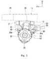
Fig. 3] Fig. 3 is a side view of the front axle casing. - [
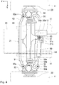
Fig. 4] Fig. 4 is a bottom view of the front axle casing. - [
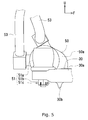
Fig. 5] Fig. 5 is an enlarged side view of a protruding part. - [
Fig. 6] Fig. 6 is an enlarged bottom view of the protruding part. - [
Fig. 7] Fig. 7 is an explanatory drawing of the protruding part. (a) is an enlarged front view, and (b) is an enlarged rear view. - [
Fig. 8] Fig. 8 is an enlarged bottom view of a protruding part of a modification. (a) is a drawing of a protruding part which is substantially U-like shaped when viewed in bottom, and (b) is a drawing of a protruding part which is substantially V-like shaped when viewed in bottom. - [
Fig. 9] Fig. 9 is an enlarged bottom view of a protruding part of a modification which is substantially L-like shaped when viewed in bottom. - Next, an embodiment of the present invention is explained.
- Firstly, an entire configuration of a
work vehicle 1 according to an embodiment of the present invention is explained. - The
work vehicle 1 of this embodiment is a tractor. However, an object to which the work vehicle according to the present invention is not limited to the tractor. - Below, a direction of an arrow F in
Fig. 1 is regarded as the front direction so as to specify the longitudinal direction of thework vehicle 1. - Below, a direction of an arrow U in
Fig. 1 is regarded as the upper direction so as to specify the vertical direction of thework vehicle 1. - Below, a direction of an arrow L in
Fig. 1 is regarded as the left direction so as to specify the lateral direction of thework vehicle 1. - As shown in
Fig. 1 , in thework vehicle 1, abody frame 10 is arranged so that a lengthwise direction thereof is arranged along the longitudinal direction. - The
body frame 10 is configured by welding afront axle bracket 12 via a pair of reinforcement plates to a pair ofbeams 11 which are arranged at a predetermined interval while a lengthwise direction thereof is arranged along the longitudinal direction. - A front part of the
body frame 10 supports an engine 2 via an engine bracket. The engine 2 is covered by abonnet 3 or the like. - The front part of the
body frame 10 is supported via afront axle casing 30 by a pair offront wheels 4. A rear part of thebody frame 10 is supported via atransmission casing 60 andrear axle casings 61 by a pair ofrear wheels 5. - In an upper part of the
body frame 10, an operation part 6 is arranged. The operation part 6 has asteering wheel 6a, aseat 6b and the like. - The
steering wheel 6a can change a steering angle of thefront wheels 4 by apower steering cylinder 50 that arod 50b is extended and contracted following rotation direction of thesteering wheel 6a so as to steer the work vehicle 1 (seeFig. 2 ). Theseat 6b is arranged above therear wheels 5 so that an operator can sit thereon. - Behind the operation part 6, a work
machine equipment device 7 is provided. By connecting a work machine such as a rotary tilling device to a rear end of atop link 7a and a rear end of alower link 7b, the workmachine equipment device 7 equips a rea end of thework vehicle 1 with the work machine. - In the
work vehicle 1, by attaching afront hitch 20 equipped with a weight to a front end of thebody frame 10, loss of weight balance in the longitudinal direction caused by equipment of the work machine is rectified. - As shown in
Figs. 1 and2 , thefront hitch 20 is a platy member which is U-like shaped when viewed in plan, and afront axle bracket 21 is welded to an inner side thereof. - The
front axle casing 30 is attached via the twofront axle brackets body frame 10. - The
front wheels 4 are attached via a pair offront axles 33 to left and right surfaces of thefront axle casing 30. - The
power steering cylinder 50 is attached viaconnection members front axle casing 30. - Configurations of the
front axle casing 30 and thepower steering cylinder 50 are described in detail later. - As shown in
Fig. 1 , thetransmission casing 60 in which a speed change device is provided is attached to the rear part of thebody frame 10. - The
top link 7a of the workmachine equipment device 7 is connected rotatably to a rear part of thetransmission casing 60. - A pair of
rear axle casings 61 is supported respectively by left and right side surfaces of thetransmission casing 60. - The
rear wheels 5 are attached via a pair ofrear axles 62 to therear axle casings 61. - The
lower link 7b of the workmachine equipment device 7 is connected rotatably to thetransmission casing 60 or therear axle casings 61. - In the
work vehicle 1, power of the engine 2 is speed-changed in the speed change device, and subsequently, the power of the engine 2 speed-changed in the speed change device can be transmitted via thefront axles 33 to thefront wheels 4 and can be transmitted via therear axles 62 to therear wheels 5. - The power of the engine 2 is transmitted to the
front wheels 4 and therear wheels 5 so as to drive rotatively thefront wheels 4 and therear wheels 5, whereby thework vehicle 1 travels. - The
work vehicle 1 can transmits the power of the engine 2 speed-changed in the speed change device to the work machine. Accordingly, thework vehicle 1 drives the work machine. - Next, a configuration of the
front axle casing 30 is explained. - As shown in
Figs. 2 and3 , thefront axle casing 30 is a substantially cylindrical member whose lengthwise direction is along the lateral direction. An axle driven by transmitting power from the engine 2 thereto and the like are housed in thefront axle casing 30. - In the
front axle casing 30, a shaft projected longitudinally from an upper end of a lateral center is inserted into holes formed in the twofront axle brackets front axle casing 30 is supported by the twofront axle brackets - A pair of
gear casings 31, a pair ofgear boxes 32 and the pair of thefront axles 33 are attached to thefront axle casing 30. - Each of the
gear casings 31 is a hollow member whose lengthwise direction is along a direction tilted slightly concerning the vertical direction. A kingpin connected to the axel in thefront axle casing 30 and the like are housed in thegear casings 31. - The
gear casings 31 are attached to lateral ends of thefront axle casing 30. - Each of the
gear boxes 32 is a hollow member whose lengthwise direction is along the lengthwise direction of thegear casings 31, that is, the direction tilted slightly concerning the vertical direction. - The
gear boxes 32 are attached respectively to lower sides of lateral ends of thegear casings 31. - The
gear boxes 32 are supported via the kingpin and the like so as to be rotatable relatively to thegear casings 31. -
Knuckle arms 32a are formed integrally with thegear boxes 32. - The
knuckle arms 32a are formed at upper sides of thegear boxes 32 and projected toward an inner side of thework vehicle 1 from front and rear sides of thegear boxes 32. - A
transmission rod 40 is attached via ball joints or the like to front sides of theknuckle arms 32a of thegear boxes 32. A lateral middle part of thetransmission rod 40 is extended straightly and both lateral sides thereof are extended smoothly along directions tilted concerning the lateral direction so as to connect thegear boxes 32. - The
front axles 33 are attached respectively to outer sides of thegear boxes 32 and support thefront wheels 4 at the outer sides of thegear boxes 32. - Next, a configuration of the
power steering cylinder 50 is explained. - The
power steering cylinder 50 is a hydraulic cylinder that therod 50b is extended and contracted by supplying pressure oil to a right side (a side extending therod 50b) or a left side (a side contracting therod 50b) of amain body 50a. - Two
pipes 53 are connected to left and right sides of themain body 50a of thepower steering cylinder 50. Each of thepipes 53 communicates themain body 50a of thepower steering cylinder 50 with a hydraulic pump via a switching valve provided in a middle part of thepipe 53. - The hydraulic pump is driven by power from the engine 2 and supplies pressure oil to the
power steering cylinder 50. At this time, the switching valves are switched corresponding to a rotation direction of thesteering wheel 6a, and the pressure oil supplied from the hydraulic pump is supplied to the left side or the right side of themain body 50a of thepower steering cylinder 50. - Accordingly, the
power steering cylinder 50 extends and contracts therod 50b corresponding to the rotation direction of thesteering wheel 6a. - The
main body 50a of thepower steering cylinder 50 is attached via theconnection member 51 to thefront axle casing 30. - The
rod 50b of thepower steering cylinder 50 is attached via theconnection members 52 to a rear side of theknuckle arm 32a of theleft gear box 32. - Accordingly, the
power steering cylinder 50 extends therod 50b so as to push leftward the rear side of theknuckle arm 32a of theleft gear box 32. Namely, thepower steering cylinder 50 rotates theleft gear box 32 clockwise inFig. 2 . - At this time, the
right gear box 32 is pushed rightward via thetransmission rod 40 and theknuckle arm 32a. - Accordingly, the
power steering cylinder 50 rotates thegear boxes 32 clockwise inFig. 2 so as to rotate thefront wheels 4 clockwise inFig. 2 . - The
power steering cylinder 50 contracts therod 50b so as to pull rightward the rear side of theknuckle arm 32a of theleft gear box 32. Namely, thepower steering cylinder 50 rotates theleft gear box 32 counterclockwise inFig. 2 . - At this time, the
right gear box 32 is pulled leftward via thetransmission rod 40 and theknuckle arm 32a. - Accordingly, the
power steering cylinder 50 rotates thegear boxes 32 counterclockwise inFig. 2 so as to rotate thefront wheels 4 counterclockwise inFig. 2 . - As the above, in the
work vehicle 1, the steering angle of thefront wheels 4 can be changed so as to steer thework vehicle 1. - Next, a configuration of attaching the
power steering cylinder 50 to thefront axle casing 30 is explained. - As shown in
Figs. 3 and4 , in thefront axle casing 30, asupport part 30a is formed as a part to which themain body 50a of thepower steering cylinder 50 is attached. - The
support part 30a is formed at a slightly right side from a lateral center of thefront axle casing 30 and projected rearward from thefront axle casing 30. Thesupport part 30a of this embodiment is formed at a lower end of thefront axle casing 30, and a lower surface of thesupport part 30a is arranged below a lower surface of thefront axle casing 30. - A lateral width of the
support part 30a becomes shorter toward a rear side and a rear end of thesupport part 30a is formed substantially semicircular when viewed in plan. As shown inFigs. 4 and5 , a rear end of the lower surface of thesupport part 30a is arranged slightly upper than the other part thereof. - A
protruding part 30b is formed at a rear side of thesupport part 30a. - The protruding
part 30b is projected lower than thesupport part 30a and formed substantially rectangular when viewed in bottom while a lengthwise direction thereof is arranged along the lateral direction. - Namely, the protruding
part 30b is projected lower partially than thefront axle casing 30 and can be looked when viewed in front, that is, when viewed from the front side of thework vehicle 1. - The
main body 50a of thepower steering cylinder 50 is attached via theconnection member 51 to a rear end of thesupport part 30a. - As shown in
Figs. 5 and6 , theconnection member 51 has a ball joint 51a, alock nut 51b and asplit pin 51 c. - The ball joint 51a includes a ball stud whose upper end is formed spherically and an outer peripheral surface of whose lower end is formed therein with a male screw, a socket covering a spherical part of the ball stud, and the like.
- A shaft part of the ball joint 51a formed integrally with a side surface of the socket is connected to the
main body 50a of thepower steering cylinder 50. A lower end of the ball stud of the ball joint 51a is inserted downward into a hole formed at the rear end of thesupport part 30a of thefront axle casing 30. - A lower end of the ball joint 51a is arranged lower than the
support part 30a of thefront axle casing 30 so as to be projected downward over thesupport part 30a of thefront axle casing 30. - The
lock nut 51b is formed by making a plurality of notched parts in a lower part of a nut at uniform intervals while phases thereof are shifted. Thelock nut 51b is attached to the lower end of the ball joint 51a. - Accordingly, the
lock nut 51b is arranged below thesupport part 30a of thefront axle casing 30. - A front end of the
split pin 51c is inserted into thelock nut 51b via the notched part of thelock nut 51b and inserted into a hole formed in the lower end of the ball joint 51a. - The front end of the
split pin 51c is projected former than the ball joint 51a and thelock nut 51b. The front end of thesplit pin 51c is bent so as to fix the ball joint 51a. - Accordingly, the
split pin 51c is arranged below thesupport part 30a of thefront axle casing 30. - As the above, the
main body 50a of thepower steering cylinder 50 is attached to thesupport part 30a by theconnection member 51. - The protruding
part 30b of thefront axle casing 30 is arranged before the lower end of the ball joint 51a, thelock nut 51b and thesplit pin 51c of theconnection member 51, that is, before the part of theconnection member 51 arranged below thesupport part 30a. - The part of the
connection member 51 arranged below thesupport part 30a is projected downward over thesupport part 30a when viewed in front. - Hereinafter, the part of the
connection member 51 arranged below thesupport part 30a is referred to as "a projection part of theconnection member 51". - As shown in
Fig. 7 , a lower end of theprotruding part 30b is arranged lower than the projection part of theconnection member 51. - A left end of the
protruding part 30b is arranged at the left of the projection part of theconnection member 51. - A right end of the
protruding part 30b is arranged at the right of the projection part of theconnection member 51. - Accordingly, the projection part of the
connection member 51 overlaps theprotruding part 30b and cannot be seen when viewed in front (see theconnection member 51 shown by dotted lines inFig. 7(a) ). - As shown in
Figs. 2 and4 , therod 50b of thepower steering cylinder 50 is attached via theconnection member 52 to the rear side of theknuckle arm 32a of theleft gear box 32. - The
connection member 52 has a ball joint 52a, alock nut 52b and asplit pin 52c. - The ball joint 52a, the
lock nut 52b and thesplit pin 52c are attached to therod 50b of thepower steering cylinder 50 and the rear side of theknuckle arm 32a in the same manner as the ball joint 51a, thelock nut 51b and thesplit pin 51c of theconnection member 51. - At this time, the
connection member 52 is arranged behind thegear casing 31 and thegear box 32. - Accordingly, the
power steering cylinder 50 is arranged behind thefront axle casing 30 while the lengthwise direction thereof is along a direction tilted slightly concerning the lateral direction. - As the above, in the
work vehicle 1, thepower steering cylinder 50 is attached to thefront axle casing 30. - In the
work vehicle 1, for example, when the steering angle of thefront wheels 4 is changed so as to avoid collision of an obstacle and thefront wheels 4 at traveling, the obstacle may touch a lower surface of thefront axle casing 30. - As shown in
Fig. 7 , the projection part of the connection member 51 (the lower end of the ball joint 51a, thelock nut 51b and thesplit pin 51c) is projected downward over thesupport part 30a. - Accordingly, in the
work vehicle 1, the obstacle may touch the projection part of theconnection member 51 at traveling. - Then, in the
work vehicle 1, the protrudingpart 30b is formed before the projection part of theconnection member 51 and the obstacle is made touch the protrudingpart 30b before touching the projection part of theconnection member 51 so as to protect the projection part of theconnection member 51 from the obstacle. - Since the lower end of the
protruding part 30b is arranged lower than the projection part of theconnection member 51, the protrudingpart 30b can protect theconnection member 51 from the obstacle certainly. - In this embodiment, the left end of the
protruding part 30b is arranged at the left of the projection part of theconnection member 51, and the right end thereof is arranged at the right of the projection part of theconnection member 51. - Accordingly, when the
work vehicle 1 passes the obstacle while turning, the protrudingpart 30b can protect theconnection member 51 from the obstacle certainly. - Namely, in the
work vehicle 1, even if thesupport part 30a is formed at the lower end of thefront axle casing 30 on account of a layout and a part of theconnection member 51 is projected downward over thefront axle casing 30, theconnection member 51 can be prevented from contacting the obstacle at traveling. - Namely, in the
work vehicle 1, theconnection member 51 can be prevented from contacting the obstacle at traveling without any restriction of the layout. - As the above, in the
front axle casing 30 of thework vehicle 1, the protrudingpart 30b which is projected from thesupport part 30a so as to cover theconnection member 51 when viewed from the front of the work vehicle 1 (when viewed in front) is formed. - Covering the
connection member 51 means that the whole projection part of theconnection member 51 overlaps theprotruding part 30b and cannot be seen when viewed in front as shown inFig. 7(a) . - Namely, the shape covering the
connection member 51 means the shape that the lower end is extended downward over the projection part of theconnection member 51, the left end is extended leftward over the projection part of theconnection member 51, and the right end is extended rightward over the projection part of theconnection member 51 such as the protrudingpart 30b of this embodiment. - The shape of the protruding part is not limited to this embodiment.
- The protruding part may alternatively be substantially U-like shaped when viewed in bottom like a
protruding part 130b shown inFig. 8(a) or substantially V-like shaped when viewed in bottom like aprotruding part 230b shown inFig. 8(b) . - A lateral center of the
protruding part part - Accordingly, in the
work vehicle 1, the obstacle colliding theprotruding part connection member 51. - Accordingly, in the
work vehicle 1, the projection part of theconnection member 51 can be protected from the obstacle more certainly, whereby theconnection member 51 can be prevented from contacting the obstacle at traveling more certainly. - As the above, the protruding
part 130b is formed in thesupport part 30a so as to be curved toward the front side of thework vehicle 1. - As the above, the protruding
part 230b is formed in thesupport part 30a so as to be bent toward the front side of thework vehicle 1. - The protruding part may alternatively be substantially L-like shaped when viewed in side wherein a lower end thereof is extended rearward like a
protruding part 330b shown inFig. 9 . - Accordingly, the protruding
part 330b covers the projection part of theconnection member 51 when viewed in side. - Accordingly, in the
work vehicle 1, the projection part of theconnection member 51 can be protected from the obstacle more certainly, whereby theconnection member 51 can be prevented from contacting the obstacle at traveling more certainly. - The present invention can be used for a work vehicle in which a power steering cylinder is attached to a front axle casing.
-
- 1
- work vehicle
- 30
- front axle casing
- 30a
- support part
- 30b
- protruding part
- 50
- power steering cylinder
- 51
- connection member
Claims (4)
- A work vehicle in which a power steering cylinder is attached to a front axle casing, characterized in that
the front axle casing is formed therein with a support part to which the power steering cylinder is attached by a connection member, and a protruding part protruding from the support part so as to cover the connection member when viewed from the front side of the work vehicle. - The work vehicle according to claim 1, wherein the protruding part is formed in the support part so as to be curved or bent toward a front side of the work vehicle.
- The work vehicle according to claim 1, wherein a lower end of the protruding part is extended rearward when viewed in side.
- The work vehicle according to claim 2, wherein a lower end of the protruding part is extended rearward when viewed in side.
Applications Claiming Priority (2)
| Application Number | Priority Date | Filing Date | Title |
|---|---|---|---|
| JP2013204705A JP6178195B2 (en) | 2013-09-30 | 2013-09-30 | Work vehicle |
| PCT/JP2014/075848 WO2015046499A1 (en) | 2013-09-30 | 2014-09-29 | Work vehicle |
Publications (3)
| Publication Number | Publication Date |
|---|---|
| EP3053770A1 true EP3053770A1 (en) | 2016-08-10 |
| EP3053770A4 EP3053770A4 (en) | 2017-05-10 |
| EP3053770B1 EP3053770B1 (en) | 2019-02-27 |
Family
ID=52743622
Family Applications (1)
| Application Number | Title | Priority Date | Filing Date |
|---|---|---|---|
| EP14848714.3A Active EP3053770B1 (en) | 2013-09-30 | 2014-09-29 | Work vehicle |
Country Status (4)
| Country | Link |
|---|---|
| US (1) | US9731754B2 (en) |
| EP (1) | EP3053770B1 (en) |
| JP (1) | JP6178195B2 (en) |
| WO (1) | WO2015046499A1 (en) |
Families Citing this family (3)
| Publication number | Priority date | Publication date | Assignee | Title |
|---|---|---|---|---|
| EP3053810B1 (en) * | 2013-09-30 | 2018-02-21 | Yanmar Co., Ltd. | Work vehicle |
| CN103738136B (en) * | 2014-01-27 | 2017-02-15 | 徐州重型机械有限公司 | Independent suspension system and crane with same |
| DE202024102217U1 (en) * | 2024-04-30 | 2025-08-04 | Dana Italia S.R.L. | Arrangement for a steering system of a vehicle |
Family Cites Families (4)
| Publication number | Priority date | Publication date | Assignee | Title |
|---|---|---|---|---|
| JPH0558560U (en) * | 1992-01-17 | 1993-08-03 | ヤンマーディーゼル株式会社 | Hydraulic cylinder mounting structure for hydraulic steering mechanism |
| JPH107009A (en) * | 1996-06-19 | 1998-01-13 | Kanzaki Kokyukoki Mfg Co Ltd | Installation structure of power steering cylinder |
| JP2003081108A (en) * | 2001-09-11 | 2003-03-19 | Iseki & Co Ltd | All hydraulic steering system |
| JP5189963B2 (en) * | 2008-11-14 | 2013-04-24 | ヤンマー株式会社 | Work vehicle |
-
2013
- 2013-09-30 JP JP2013204705A patent/JP6178195B2/en active Active
-
2014
- 2014-09-29 US US15/025,005 patent/US9731754B2/en not_active Expired - Fee Related
- 2014-09-29 WO PCT/JP2014/075848 patent/WO2015046499A1/en not_active Ceased
- 2014-09-29 EP EP14848714.3A patent/EP3053770B1/en active Active
Non-Patent Citations (2)
| Title |
|---|
| No further relevant documents disclosed * |
| See also references of WO2015046499A1 * |
Also Published As
| Publication number | Publication date |
|---|---|
| JP2015067213A (en) | 2015-04-13 |
| EP3053770A4 (en) | 2017-05-10 |
| US9731754B2 (en) | 2017-08-15 |
| WO2015046499A1 (en) | 2015-04-02 |
| JP6178195B2 (en) | 2017-08-09 |
| US20160272240A1 (en) | 2016-09-22 |
| EP3053770B1 (en) | 2019-02-27 |
Similar Documents
| Publication | Publication Date | Title |
|---|---|---|
| US8789646B2 (en) | Steering apparatus of for a tractor | |
| US9919730B2 (en) | Steering device and vehicle including the same | |
| US20130240282A1 (en) | Electric Drive Axle Configuration | |
| US9114682B1 (en) | Steering for independent suspension system | |
| US20130000996A1 (en) | Mobile machine with a support system | |
| US8910741B2 (en) | Steering device for tractor | |
| US20200062303A1 (en) | Wheel suspension device having single-wheel steering for a motor vehicle with driving of the steered wheels | |
| BR112015015527B1 (en) | INTERMEDIATE STEERING ARM | |
| JPH107009A (en) | Installation structure of power steering cylinder | |
| EP3053770B1 (en) | Work vehicle | |
| EP3717708B1 (en) | Reactive steering system for a work vehicle having an articulated chassis | |
| US7758058B2 (en) | Front Steerable device for a vehicle | |
| US9381805B2 (en) | Tractor | |
| EP3650320B1 (en) | Fender support structure and work vehicle equipped with same | |
| US8978810B2 (en) | Tractor | |
| JP2010264874A (en) | Front axle mechanism | |
| JP2025091844A (en) | Front axle case and work vehicle | |
| JPH0324454Y2 (en) | ||
| JP2008037160A (en) | Traveling vehicle for working | |
| JP2018043675A (en) | Rod connection structure for travelling vehicle | |
| JP2010095172A (en) | Vehicular steering device | |
| JPH0565755U (en) | Power steering for mobile farms | |
| JP2003081127A (en) | Paddy working machine | |
| JPS6280161A (en) | vehicle steering device |
Legal Events
| Date | Code | Title | Description |
|---|---|---|---|
| PUAI | Public reference made under article 153(3) epc to a published international application that has entered the european phase |
Free format text: ORIGINAL CODE: 0009012 |
|
| 17P | Request for examination filed |
Effective date: 20160502 |
|
| AK | Designated contracting states |
Kind code of ref document: A1 Designated state(s): AL AT BE BG CH CY CZ DE DK EE ES FI FR GB GR HR HU IE IS IT LI LT LU LV MC MK MT NL NO PL PT RO RS SE SI SK SM TR |
|
| AX | Request for extension of the european patent |
Extension state: BA ME |
|
| DAX | Request for extension of the european patent (deleted) | ||
| A4 | Supplementary search report drawn up and despatched |
Effective date: 20170406 |
|
| RIC1 | Information provided on ipc code assigned before grant |
Ipc: B62D 5/06 20060101AFI20170401BHEP Ipc: B62D 9/00 20060101ALN20170401BHEP |
|
| STAA | Information on the status of an ep patent application or granted ep patent |
Free format text: STATUS: EXAMINATION IS IN PROGRESS |
|
| 17Q | First examination report despatched |
Effective date: 20180430 |
|
| REG | Reference to a national code |
Ref country code: DE Ref legal event code: R079 Ref document number: 602014042043 Country of ref document: DE Free format text: PREVIOUS MAIN CLASS: B60K0017320000 Ipc: B62D0005060000 |
|
| GRAP | Despatch of communication of intention to grant a patent |
Free format text: ORIGINAL CODE: EPIDOSNIGR1 |
|
| STAA | Information on the status of an ep patent application or granted ep patent |
Free format text: STATUS: GRANT OF PATENT IS INTENDED |
|
| RIC1 | Information provided on ipc code assigned before grant |
Ipc: B62D 5/06 20060101AFI20180816BHEP Ipc: B62D 9/00 20060101ALN20180816BHEP |
|
| RIC1 | Information provided on ipc code assigned before grant |
Ipc: B62D 9/00 20060101ALN20180829BHEP Ipc: B62D 5/06 20060101AFI20180829BHEP |
|
| INTG | Intention to grant announced |
Effective date: 20180911 |
|
| GRAS | Grant fee paid |
Free format text: ORIGINAL CODE: EPIDOSNIGR3 |
|
| GRAA | (expected) grant |
Free format text: ORIGINAL CODE: 0009210 |
|
| STAA | Information on the status of an ep patent application or granted ep patent |
Free format text: STATUS: THE PATENT HAS BEEN GRANTED |
|
| RIN1 | Information on inventor provided before grant (corrected) |
Inventor name: HANAFUSA, MASAHIRO Inventor name: DAIYAKUJI, TAIHEI |
|
| AK | Designated contracting states |
Kind code of ref document: B1 Designated state(s): AL AT BE BG CH CY CZ DE DK EE ES FI FR GB GR HR HU IE IS IT LI LT LU LV MC MK MT NL NO PL PT RO RS SE SI SK SM TR |
|
| REG | Reference to a national code |
Ref country code: GB Ref legal event code: FG4D |
|
| REG | Reference to a national code |
Ref country code: CH Ref legal event code: EP |
|
| REG | Reference to a national code |
Ref country code: AT Ref legal event code: REF Ref document number: 1100900 Country of ref document: AT Kind code of ref document: T Effective date: 20190315 |
|
| REG | Reference to a national code |
Ref country code: IE Ref legal event code: FG4D |
|
| REG | Reference to a national code |
Ref country code: DE Ref legal event code: R096 Ref document number: 602014042043 Country of ref document: DE |
|
| REG | Reference to a national code |
Ref country code: NL Ref legal event code: MP Effective date: 20190227 |
|
| REG | Reference to a national code |
Ref country code: LT Ref legal event code: MG4D |
|
| PG25 | Lapsed in a contracting state [announced via postgrant information from national office to epo] |
Ref country code: LT Free format text: LAPSE BECAUSE OF FAILURE TO SUBMIT A TRANSLATION OF THE DESCRIPTION OR TO PAY THE FEE WITHIN THE PRESCRIBED TIME-LIMIT Effective date: 20190227 Ref country code: NL Free format text: LAPSE BECAUSE OF FAILURE TO SUBMIT A TRANSLATION OF THE DESCRIPTION OR TO PAY THE FEE WITHIN THE PRESCRIBED TIME-LIMIT Effective date: 20190227 Ref country code: NO Free format text: LAPSE BECAUSE OF FAILURE TO SUBMIT A TRANSLATION OF THE DESCRIPTION OR TO PAY THE FEE WITHIN THE PRESCRIBED TIME-LIMIT Effective date: 20190527 Ref country code: FI Free format text: LAPSE BECAUSE OF FAILURE TO SUBMIT A TRANSLATION OF THE DESCRIPTION OR TO PAY THE FEE WITHIN THE PRESCRIBED TIME-LIMIT Effective date: 20190227 Ref country code: SE Free format text: LAPSE BECAUSE OF FAILURE TO SUBMIT A TRANSLATION OF THE DESCRIPTION OR TO PAY THE FEE WITHIN THE PRESCRIBED TIME-LIMIT Effective date: 20190227 Ref country code: PT Free format text: LAPSE BECAUSE OF FAILURE TO SUBMIT A TRANSLATION OF THE DESCRIPTION OR TO PAY THE FEE WITHIN THE PRESCRIBED TIME-LIMIT Effective date: 20190627 |
|
| PG25 | Lapsed in a contracting state [announced via postgrant information from national office to epo] |
Ref country code: IS Free format text: LAPSE BECAUSE OF FAILURE TO SUBMIT A TRANSLATION OF THE DESCRIPTION OR TO PAY THE FEE WITHIN THE PRESCRIBED TIME-LIMIT Effective date: 20190627 Ref country code: BG Free format text: LAPSE BECAUSE OF FAILURE TO SUBMIT A TRANSLATION OF THE DESCRIPTION OR TO PAY THE FEE WITHIN THE PRESCRIBED TIME-LIMIT Effective date: 20190527 Ref country code: GR Free format text: LAPSE BECAUSE OF FAILURE TO SUBMIT A TRANSLATION OF THE DESCRIPTION OR TO PAY THE FEE WITHIN THE PRESCRIBED TIME-LIMIT Effective date: 20190528 Ref country code: RS Free format text: LAPSE BECAUSE OF FAILURE TO SUBMIT A TRANSLATION OF THE DESCRIPTION OR TO PAY THE FEE WITHIN THE PRESCRIBED TIME-LIMIT Effective date: 20190227 Ref country code: LV Free format text: LAPSE BECAUSE OF FAILURE TO SUBMIT A TRANSLATION OF THE DESCRIPTION OR TO PAY THE FEE WITHIN THE PRESCRIBED TIME-LIMIT Effective date: 20190227 Ref country code: HR Free format text: LAPSE BECAUSE OF FAILURE TO SUBMIT A TRANSLATION OF THE DESCRIPTION OR TO PAY THE FEE WITHIN THE PRESCRIBED TIME-LIMIT Effective date: 20190227 |
|
| REG | Reference to a national code |
Ref country code: AT Ref legal event code: MK05 Ref document number: 1100900 Country of ref document: AT Kind code of ref document: T Effective date: 20190227 |
|
| PG25 | Lapsed in a contracting state [announced via postgrant information from national office to epo] |
Ref country code: CZ Free format text: LAPSE BECAUSE OF FAILURE TO SUBMIT A TRANSLATION OF THE DESCRIPTION OR TO PAY THE FEE WITHIN THE PRESCRIBED TIME-LIMIT Effective date: 20190227 Ref country code: SK Free format text: LAPSE BECAUSE OF FAILURE TO SUBMIT A TRANSLATION OF THE DESCRIPTION OR TO PAY THE FEE WITHIN THE PRESCRIBED TIME-LIMIT Effective date: 20190227 Ref country code: AL Free format text: LAPSE BECAUSE OF FAILURE TO SUBMIT A TRANSLATION OF THE DESCRIPTION OR TO PAY THE FEE WITHIN THE PRESCRIBED TIME-LIMIT Effective date: 20190227 Ref country code: RO Free format text: LAPSE BECAUSE OF FAILURE TO SUBMIT A TRANSLATION OF THE DESCRIPTION OR TO PAY THE FEE WITHIN THE PRESCRIBED TIME-LIMIT Effective date: 20190227 Ref country code: ES Free format text: LAPSE BECAUSE OF FAILURE TO SUBMIT A TRANSLATION OF THE DESCRIPTION OR TO PAY THE FEE WITHIN THE PRESCRIBED TIME-LIMIT Effective date: 20190227 Ref country code: DK Free format text: LAPSE BECAUSE OF FAILURE TO SUBMIT A TRANSLATION OF THE DESCRIPTION OR TO PAY THE FEE WITHIN THE PRESCRIBED TIME-LIMIT Effective date: 20190227 Ref country code: EE Free format text: LAPSE BECAUSE OF FAILURE TO SUBMIT A TRANSLATION OF THE DESCRIPTION OR TO PAY THE FEE WITHIN THE PRESCRIBED TIME-LIMIT Effective date: 20190227 Ref country code: IT Free format text: LAPSE BECAUSE OF FAILURE TO SUBMIT A TRANSLATION OF THE DESCRIPTION OR TO PAY THE FEE WITHIN THE PRESCRIBED TIME-LIMIT Effective date: 20190227 |
|
| REG | Reference to a national code |
Ref country code: DE Ref legal event code: R097 Ref document number: 602014042043 Country of ref document: DE |
|
| PG25 | Lapsed in a contracting state [announced via postgrant information from national office to epo] |
Ref country code: SM Free format text: LAPSE BECAUSE OF FAILURE TO SUBMIT A TRANSLATION OF THE DESCRIPTION OR TO PAY THE FEE WITHIN THE PRESCRIBED TIME-LIMIT Effective date: 20190227 Ref country code: PL Free format text: LAPSE BECAUSE OF FAILURE TO SUBMIT A TRANSLATION OF THE DESCRIPTION OR TO PAY THE FEE WITHIN THE PRESCRIBED TIME-LIMIT Effective date: 20190227 |
|
| PG25 | Lapsed in a contracting state [announced via postgrant information from national office to epo] |
Ref country code: AT Free format text: LAPSE BECAUSE OF FAILURE TO SUBMIT A TRANSLATION OF THE DESCRIPTION OR TO PAY THE FEE WITHIN THE PRESCRIBED TIME-LIMIT Effective date: 20190227 |
|
| PLBE | No opposition filed within time limit |
Free format text: ORIGINAL CODE: 0009261 |
|
| STAA | Information on the status of an ep patent application or granted ep patent |
Free format text: STATUS: NO OPPOSITION FILED WITHIN TIME LIMIT |
|
| 26N | No opposition filed |
Effective date: 20191128 |
|
| PG25 | Lapsed in a contracting state [announced via postgrant information from national office to epo] |
Ref country code: SI Free format text: LAPSE BECAUSE OF FAILURE TO SUBMIT A TRANSLATION OF THE DESCRIPTION OR TO PAY THE FEE WITHIN THE PRESCRIBED TIME-LIMIT Effective date: 20190227 |
|
| PG25 | Lapsed in a contracting state [announced via postgrant information from national office to epo] |
Ref country code: TR Free format text: LAPSE BECAUSE OF FAILURE TO SUBMIT A TRANSLATION OF THE DESCRIPTION OR TO PAY THE FEE WITHIN THE PRESCRIBED TIME-LIMIT Effective date: 20190227 |
|
| PG25 | Lapsed in a contracting state [announced via postgrant information from national office to epo] |
Ref country code: MC Free format text: LAPSE BECAUSE OF FAILURE TO SUBMIT A TRANSLATION OF THE DESCRIPTION OR TO PAY THE FEE WITHIN THE PRESCRIBED TIME-LIMIT Effective date: 20190227 |
|
| REG | Reference to a national code |
Ref country code: CH Ref legal event code: PL |
|
| PG25 | Lapsed in a contracting state [announced via postgrant information from national office to epo] |
Ref country code: LI Free format text: LAPSE BECAUSE OF NON-PAYMENT OF DUE FEES Effective date: 20190930 Ref country code: CH Free format text: LAPSE BECAUSE OF NON-PAYMENT OF DUE FEES Effective date: 20190930 Ref country code: LU Free format text: LAPSE BECAUSE OF NON-PAYMENT OF DUE FEES Effective date: 20190929 Ref country code: IE Free format text: LAPSE BECAUSE OF NON-PAYMENT OF DUE FEES Effective date: 20190929 |
|
| REG | Reference to a national code |
Ref country code: BE Ref legal event code: MM Effective date: 20190930 |
|
| PG25 | Lapsed in a contracting state [announced via postgrant information from national office to epo] |
Ref country code: BE Free format text: LAPSE BECAUSE OF NON-PAYMENT OF DUE FEES Effective date: 20190930 |
|
| GBPC | Gb: european patent ceased through non-payment of renewal fee |
Effective date: 20190929 |
|
| REG | Reference to a national code |
Ref country code: DE Ref legal event code: R082 Ref document number: 602014042043 Country of ref document: DE Representative=s name: JOSTARNDT PATENTANWALTS-AG, DE Ref country code: DE Ref legal event code: R081 Ref document number: 602014042043 Country of ref document: DE Owner name: YANMAR POWER TECHNOLOGY CO., LTD., JP Free format text: FORMER OWNER: YANMAR CO., LTD., OSAKA-SHI, JP |
|
| PG25 | Lapsed in a contracting state [announced via postgrant information from national office to epo] |
Ref country code: GB Free format text: LAPSE BECAUSE OF NON-PAYMENT OF DUE FEES Effective date: 20190929 |
|
| PG25 | Lapsed in a contracting state [announced via postgrant information from national office to epo] |
Ref country code: CY Free format text: LAPSE BECAUSE OF FAILURE TO SUBMIT A TRANSLATION OF THE DESCRIPTION OR TO PAY THE FEE WITHIN THE PRESCRIBED TIME-LIMIT Effective date: 20190227 |
|
| PG25 | Lapsed in a contracting state [announced via postgrant information from national office to epo] |
Ref country code: HU Free format text: LAPSE BECAUSE OF FAILURE TO SUBMIT A TRANSLATION OF THE DESCRIPTION OR TO PAY THE FEE WITHIN THE PRESCRIBED TIME-LIMIT; INVALID AB INITIO Effective date: 20140929 Ref country code: MT Free format text: LAPSE BECAUSE OF FAILURE TO SUBMIT A TRANSLATION OF THE DESCRIPTION OR TO PAY THE FEE WITHIN THE PRESCRIBED TIME-LIMIT Effective date: 20190227 |
|
| PG25 | Lapsed in a contracting state [announced via postgrant information from national office to epo] |
Ref country code: MK Free format text: LAPSE BECAUSE OF FAILURE TO SUBMIT A TRANSLATION OF THE DESCRIPTION OR TO PAY THE FEE WITHIN THE PRESCRIBED TIME-LIMIT Effective date: 20190227 |
|
| PGFP | Annual fee paid to national office [announced via postgrant information from national office to epo] |
Ref country code: DE Payment date: 20250919 Year of fee payment: 12 |
|
| PGFP | Annual fee paid to national office [announced via postgrant information from national office to epo] |
Ref country code: FR Payment date: 20250922 Year of fee payment: 12 |