EP3053749A1 - Ink-jet printer - Google Patents
Ink-jet printer Download PDFInfo
- Publication number
- EP3053749A1 EP3053749A1 EP14850874.0A EP14850874A EP3053749A1 EP 3053749 A1 EP3053749 A1 EP 3053749A1 EP 14850874 A EP14850874 A EP 14850874A EP 3053749 A1 EP3053749 A1 EP 3053749A1
- Authority
- EP
- European Patent Office
- Prior art keywords
- platen
- inkjet printer
- holes
- recording medium
- heater
- Prior art date
- Legal status (The legal status is an assumption and is not a legal conclusion. Google has not performed a legal analysis and makes no representation as to the accuracy of the status listed.)
- Withdrawn
Links
- 238000010438 heat treatment Methods 0.000 claims abstract description 11
- 238000004804 winding Methods 0.000 claims description 13
- 230000006870 function Effects 0.000 description 6
- 238000004891 communication Methods 0.000 description 5
- 238000007639 printing Methods 0.000 description 4
- 230000000630 rising effect Effects 0.000 description 4
- 238000001816 cooling Methods 0.000 description 3
- 230000000740 bleeding effect Effects 0.000 description 2
- 230000008878 coupling Effects 0.000 description 2
- 238000010168 coupling process Methods 0.000 description 2
- 238000005859 coupling reaction Methods 0.000 description 2
- 238000010586 diagram Methods 0.000 description 2
- 230000000694 effects Effects 0.000 description 1
- 238000005265 energy consumption Methods 0.000 description 1
- 239000004973 liquid crystal related substance Substances 0.000 description 1
- 239000000463 material Substances 0.000 description 1
- 239000002184 metal Substances 0.000 description 1
- 239000011347 resin Substances 0.000 description 1
- 229920005989 resin Polymers 0.000 description 1
- 230000000717 retained effect Effects 0.000 description 1
- 238000011144 upstream manufacturing Methods 0.000 description 1
Images




Classifications
-
- B—PERFORMING OPERATIONS; TRANSPORTING
- B41—PRINTING; LINING MACHINES; TYPEWRITERS; STAMPS
- B41J—TYPEWRITERS; SELECTIVE PRINTING MECHANISMS, i.e. MECHANISMS PRINTING OTHERWISE THAN FROM A FORME; CORRECTION OF TYPOGRAPHICAL ERRORS
- B41J11/00—Devices or arrangements of selective printing mechanisms, e.g. ink-jet printers or thermal printers, for supporting or handling copy material in sheet or web form
- B41J11/0015—Devices or arrangements of selective printing mechanisms, e.g. ink-jet printers or thermal printers, for supporting or handling copy material in sheet or web form for treating before, during or after printing or for uniform coating or laminating the copy material before or after printing
- B41J11/002—Curing or drying the ink on the copy materials, e.g. by heating or irradiating
- B41J11/0024—Curing or drying the ink on the copy materials, e.g. by heating or irradiating using conduction means, e.g. by using a heated platen
- B41J11/00244—Means for heating the copy materials before or during printing
-
- B—PERFORMING OPERATIONS; TRANSPORTING
- B41—PRINTING; LINING MACHINES; TYPEWRITERS; STAMPS
- B41J—TYPEWRITERS; SELECTIVE PRINTING MECHANISMS, i.e. MECHANISMS PRINTING OTHERWISE THAN FROM A FORME; CORRECTION OF TYPOGRAPHICAL ERRORS
- B41J11/00—Devices or arrangements of selective printing mechanisms, e.g. ink-jet printers or thermal printers, for supporting or handling copy material in sheet or web form
- B41J11/0045—Guides for printing material
- B41J11/0055—Lateral guides, e.g. guides for preventing skewed conveyance of printing material
-
- B—PERFORMING OPERATIONS; TRANSPORTING
- B41—PRINTING; LINING MACHINES; TYPEWRITERS; STAMPS
- B41J—TYPEWRITERS; SELECTIVE PRINTING MECHANISMS, i.e. MECHANISMS PRINTING OTHERWISE THAN FROM A FORME; CORRECTION OF TYPOGRAPHICAL ERRORS
- B41J11/00—Devices or arrangements of selective printing mechanisms, e.g. ink-jet printers or thermal printers, for supporting or handling copy material in sheet or web form
- B41J11/0085—Using suction for maintaining printing material flat
-
- B—PERFORMING OPERATIONS; TRANSPORTING
- B41—PRINTING; LINING MACHINES; TYPEWRITERS; STAMPS
- B41J—TYPEWRITERS; SELECTIVE PRINTING MECHANISMS, i.e. MECHANISMS PRINTING OTHERWISE THAN FROM A FORME; CORRECTION OF TYPOGRAPHICAL ERRORS
- B41J11/00—Devices or arrangements of selective printing mechanisms, e.g. ink-jet printers or thermal printers, for supporting or handling copy material in sheet or web form
- B41J11/02—Platens
- B41J11/06—Flat page-size platens or smaller flat platens having a greater size than line-size platens
-
- B—PERFORMING OPERATIONS; TRANSPORTING
- B41—PRINTING; LINING MACHINES; TYPEWRITERS; STAMPS
- B41J—TYPEWRITERS; SELECTIVE PRINTING MECHANISMS, i.e. MECHANISMS PRINTING OTHERWISE THAN FROM A FORME; CORRECTION OF TYPOGRAPHICAL ERRORS
- B41J15/00—Devices or arrangements of selective printing mechanisms, e.g. ink-jet printers or thermal printers, specially adapted for supporting or handling copy material in continuous form, e.g. webs
- B41J15/04—Supporting, feeding, or guiding devices; Mountings for web rolls or spindles
Definitions
- the disclosure relates to an inkjet printer which includes a platen configured to have a supporting surface for supporting a recording medium and a plurality of through-holes formed in the supporting surface, and a fan configured to produce a flow of gas, existing on the supporting surface side with respect to the through-holes, through the through-holes.
- an inkjet recording apparatus which includes an accommodating tray configured to accommodate recording sheets which are recording media, a side guide configured to regulate the rear ends of recording sheets in the accommodating tray, a recording head configured to eject ink, a platen configured to support each recording sheet onto which the recording head ejects ink, an intake fan that is a fan configured to produce a flow of gas, a slide shutter configured to be able to cover at least a part of the platen, a side pressing tool configured to be attached to the leading end portion of the slide shutter and suppress an end portion of each recording sheet from rising up from the platen, and a coupling arm configured to couple the side guide with the slide shutter, thereby transmitting linear motion of the side guide directly to the slide shutter (refer to Patent Document 1).
- the platen of the inkjet recording apparatus disclosed in Patent Document 1 has a top surface which is a supporting surface for supporting each recording sheet, and a plurality of suction holes which are through-holes formed in the top surface.
- the intake fan of the inkjet recording apparatus disclosed in Patent Document 1 is configured to produce a flow of gas, existing on the top surface side of the platen with respect to the suction holes of the platen, through the suction holes.
- the slide shutter of the inkjet recording apparatus disclosed in Patent Document 1 is configured to be able to cover at least a part of the top surface of the platen, thereby shielding at least some of the plurality of suction holes of the platen, and be able to change an area to cover the top surface of the platen.
- This slide shutter is configured to operate simultaneously with the side guide coupled with the slide shutter by the coupling arm, thereby being fixed at a position according to the width dimension of a recording sheet with respect to the platen.
- the slide shutter is formed by a member which is deformable and flexible and has a flat plate shape
- the slide shutter is configured to be able to be accommodated in a state where a range protruding from an end portion of the platen is bent, for example, downward.
- Patent Document 1 JP-A-2000-153604
- the inkjet recording apparatus disclosed in Patent Document 1 does not include a heater configured to heat the platen.
- a heater configured to heat the platen.
- an inkjet printer including a platen configured to include a supporting surface for supporting each recording medium and a plurality of through-holes formed in the supporting surface, a fan configured to produce a flow of gas, existing on the supporting surface side with respect to the through-holes, through the through-holes, and a heater configured to heat the platen, since the platen heated by the heater is cooled by the flow of gas produced by the fan, the efficiency of heating of the platen by the heater is low.
- the inventor of this application focused attention on that point.
- the disclosure provides an inkjet printer capable of improving the efficiency of heating of a platen by a heater as compared to that in the related art.
- An inkjet printer of the disclosure includes: a recording head that is configured to eject ink; a platen that is configured to support a recording medium onto which the recording head ejects ink; a heater that is configured to heat the platen; a fan that is configured to produce a flow of gas; and sheets that are configured to be able to cover at least a part of the platen, wherein the platen has a supporting surface for supporting the recording medium, and a plurality of through-holes formed in the supporting surface, wherein the fan produces the flow of gas, existing on the supporting surface side with respect to the through-holes, through the through-holes, and wherein the sheets can cover at least a part of the supporting surface, thereby capable of shielding at least some of the plurality of through-holes, and can change an area to cover the supporting surface.
- the inkjet printer of the disclosure since a part of the supporting surface of the platen which does not support a recording medium is covered by the sheets (hereinafter, referred to as a "medium non-support part"), whereby it is possible to shield the through-holes of the medium non-support part, it is possible to suppress gas from being forced to flow through the through-holes of the medium non-support part by the fan. Therefore, the inkjet printer of the disclosure can suppress cooling of the platen due to the flow of gas through the through-holes of the medium non-support part produced by the fan, and thus can improve the efficiency of heating of the platen by the heater as compared to that in the related art.
- the heater may be disposed at a position on the opposite side of the through-holes to the supporting surface side, in a space where gas getting out of the through-holes passes.
- the inkjet printer of the disclosure since the heater is disposed in the space where gas entering through-holes from the supporting surface side of the platen and getting out of the through-holes passes, gas entering through-holes from the supporting surface side of the platen and getting out of the through-holes passes the vicinity of the heater, and thus the heater can be easily cooled by the gas. Therefore, the inkjet printer of the disclosure further improves the efficiency of heating of the platen by the heater as compared to a configuration in which the heater is not disposed in the space where gas getting out of through-holes passes.
- the inkjet printer of the disclosure may include winding members that are configured to be able to wind the sheets, and fixed members that are configured to be attached to the sheets attached to the winding members and be fixable at a plurality of positions with respect to the platen.
- the sheets in a case where the sheets move with respect to the platen, the sheets are wound. Therefore, as compared to a configuration in which the sheets move with respect to the platen without being wound, it is possible to reduce a space for accommodating the sheets, and thus it is possible to reduce the size of the whole of the inkjet printer.
- the inkjet printer of the disclosure may include biasing members that are configured to bias the winding members in the winding directions of the sheets.
- the sheets can be automatically wound around the winding members by the biasing forces of the biasing members. Therefore, as compared to a configuration in which a user manually winds the sheets around the winding members, it is possible to suppress the burden of a user.
- the fixed members may be guide members that are configured to guide conveyance of the recording medium.
- the fixed members have both of a function of fixing the sheets with respect to the platen and a function of guiding conveyance of a recording medium. Therefore, as long as the fixed members are fixed with respect to the platen according to the width of a recording medium in order to make the fixed members guide conveyance of the recording medium, it is possible to improve the platen heating efficiency of the heater by the sheets.
- the inkjet printer of the disclosure can improve the efficiency of heating of the platen by the heater as compared to that in the related art.
- FIG. 1 is a perspective view of an inkjet printer 10 according to the illustrative embodiment in a state where the inkjet printer is conveying a recording medium 90 such as a sheet of paper.
- the inkjet printer 10 includes: a housing 11; a conveying device 12 configured to be disposed at a lower part of the housing 11 and convey a recording medium 90 in a sub scan direction shown by an arrow 10b and perpendicular to a main scan direction shown by an arrow 10a; a tank 13 configured to be disposed at an upper part of the housing 11 and contain ink; a guide rail 14 configured to extend in the main scan direction shown by the arrow 10a; a carriage 15 configured to be supported on the guide rail 14 so as to be movable in the main scan direction shown by the arrow 10a; a recording head 16 configured to be mounted on the carriage 15 and eject ink toward each recording medium 90; and a pressure damper 17 that is a device configured to be mounted on the carriage 15 and adjust the pressure of ink to be supplied from the tank 13 to the recording head 16 to a negative pressure of a predetermined range.
- the housing 11 accommodates the guide rail 14, the carriage 15, the recording head 16, and the pressure damper 17.
- the inkjet printer 10 is an apparatus configured to move the recording head 16 in the main scan direction, with respect to a recording medium 90 which does not move in the main scan direction shown by the arrow 10a, by the carriage 15, and eject ink from the nozzles of the recording head 16 toward the recording medium 90, thereby performing printing in the main scan direction with the recording head 16. Also, the inkjet printer 10 is an apparatus configured to convey the recording medium 90 in the sub scan direction, with respect to the recording head 16 which is not move in the sub scan direction shown by the arrow 10b, by the conveying device 12, thereby changing the position of the recording head 16 relative to the recording medium 90 in the sub scan direction whenever printing in the main scan direction finishes.
- FIG. 2 is a sectional side view of the inkjet printer 10.
- the inkjet printer 10 includes: a pre-platen 21 configured to be disposed on the upstream side of the recording head 16 in the conveyance direction of a recording medium 90 (refer to FIG. 1 ) shown by an arrow 10c in the sub scan direction shown by the arrow 10b and to support the recording medium 90; a pre-heater 22 configured to heat the pre-platen 21 in order to preheat the recording medium 90 to be conveyed toward a position facing the recording head 16; a print platen 31 that is a platen of the disclosure configured to be disposed at a position facing the recording head 16 and support the recording medium 90; a print heater 32 that is a heater of the disclosure configured to be disposed at a position facing the recording head 16 and heat the print platen 31 in order to heat the recording medium 90; an after-platen 41 configured to be disposed on the downstream side from the recording head 16 in the conveyance direction shown by the arrow 10c and support the recording medium 90; and an after-heater 42 configured to
- the print platen 31 is configured to have a supporting surface 31a for supporting each recording medium 90 and a plurality of through-holes 31b formed in the supporting surface 31a.
- the pre-heater 22 is a device configured to preheat a recording medium 90 to be conveyed toward the position facing the recording head 16, through the pre-platen 21, such that ink ejected by the recording head 16 dries up quickly from when the ink is attached to the recording medium 90.
- the print heater 32 is a device configured to be disposed at a position facing the recording head 16 and heat a recording medium 90 through the print platen 31, such that ink ejected by the recording head 16 dries up quickly from when the ink is attached to the recording medium 90.
- the after-heater 42 is a device configured to heat a recording medium 90, conveyed from the position facing the recording head 16, through the after-platen 41, such that ink ejected by the recording head 16 and attached to the recording medium 90 can surely dry up.
- ink ejected by the recording head 16 and attached to a recording medium 90 dries up quickly and surely on the recording medium 90 by heat generated by the pre-heater 22, the print heater 32, and the after-heater 42, whereby bleeding is suppressed. Therefore, the inkjet printer 10 can form high-quality images on recording media 90 with ink.
- the inkjet printer 10 includes a wall member 51 which separates a space 20a where the pre-heater 22 is disposed, and a space 30a where the print heater 32 is disposed. Also, the inkjet printer 10 includes a wall member 52 which separates the space 30a and a space 40a where the after-heater 42 is disposed. Further, the inkjet printer 10 includes a base member 53 that blocks the bottom of the space 20a, a base member 54 that blocks the bottom of the space 30a, and a base member 55 that blocks the bottom of the space 40a.
- the inkjet printer 10 includes a fan 33 configured to be attached to the base member 54 and produce a flow of gas.
- the fan 33 is configured to suck gas in the space 30a and to discharge the gas out of the space 30a, thereby lowering the atmosphere pressure of the inside of the space 30a. If the atmosphere pressure of the inside of the space 30a falls, gas existing on a side of the supporting surface 31a with respect to the through-holes 31b of the print platen 31 moves into the space 30a through the through-holes 31b.
- the fan 33 is configured to produce a flow of gas, existing on the side of the supporting surface 31a with respect to the through-holes 31b of the print platen 31, into the space 30a through the through-holes 31b.
- the print heater 32 is disposed inside the space 30a.
- the print heater 32 is disposed at a position on the opposite side of the side of the supporting surface 31a with respect to the through-holes 31b of the print platen 31, and the print heater 32 is disposed inside the space 30a where gas getting out of the through-holes 31b passes.
- FIG. 3 is a sectional front view of a part, surrounding the print platen 31, of the inkjet printer 10.
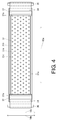
- FIG. 4 is a plan view of a part, surrounding the print platen 31, of the inkjet printer 10.
- the inkjet printer 10 (refer to FIG. 1 ) includes: sheets 34 configured to be able to cover at least a part of the print platen 31; rollers 35 that are winding members configured to be able to wind the sheets 34; spiral springs 36 that are biasing members configured to bias the rollers 35 in the winding directions of the sheets 34; and guide members 37 configured to guide conveyance of each recording medium 90.
- the sheets 34 are attached to the rollers 35 and the guide members 37.
- the sheets 34 can cover at least a part of the supporting surface 31a of the print platen 31, thereby shielding at least a part of the plurality of through-holes 31b.
- the sheets 34 can change an area to cover the supporting surface 31a, according to change in the positions of the guide members 37 related to the print platen 31.
- a material for the sheet 34 for example, a resin, a metal, or the like can be used as a material for the sheet 34.
- the rollers 35 extend in the sub scan direction shown by the arrow 10b, and are supported on the housing 11 (refer to FIG. 1 ) such that they are rotatable.
- spiral springs 36 are included inside the rollers 35. One end of each spiral spring 36 is fixed to the housing 11, and the other end thereof is fixed to a corresponding roller 35.
- the print platen 31 is provided with two guide grooves 31c formed so as to extend in the main scan direction shown by the arrow 10a and be separate from each other in the sub scan direction shown by the arrow 10b.
- the guide members 37 have protrusions (not shown) fit in the guide grooves 31c of the print platen 31, and can be moved in the main scan direction shown by the arrow 10a as the protrusions are guided along the guide grooves 31c.
- the guide members 37 can be fixed at a plurality of positions with respect to the print platen 31 by frictional forces which are generated between the guide members and the print platen 31. In other words, the guide members 37 constitute fixed members of the disclosure.
- FIG. 5 is a perspective view of a part, surrounding a guide member 37, of the inkjet printer 10 in a state where the inkjet printer is conveying a recording medium 90.
- a guide member 37 includes a rising suppressing unit 37a configured to suppress rising up of an end of a recording medium 90 in the main scan direction shown by the arrow 10a.
- FIG. 6 is a block diagram of the inkjet printer 10.
- the inkjet printer 10 includes: an operation unit 61 that is an input device such as buttons to which various operations of a user are input; a display unit 62 that is a display device such as an LCD (liquid crystal display) configured to display a variety of information; a communication unit 63 which is a communication device configured to perform communication with external apparatuses such as a PC (personal computer); the conveying device 12 and the recording head 16 described above; a carriage driving device 64 configured to move the carriage 15 (refer to FIG. 1 ) in the main scan direction shown by the arrow 10a (refer to FIG. 1 ); the pre-heater 22, the print heater 32, the after-heater 42, and the fan 33 described above; and a control unit 65 configured to control the whole of the inkjet printer 10.
- an operation unit 61 that is an input device such as buttons to which various operations of a user are input
- a display unit 62 that is a display device such as an LCD (liquid crystal display) configured to display a variety of information
- the control unit 65 includes, for example, a CPU (central processing unit), a ROM (read only memory) configured to retain programs and a variety of data, a RAM (random access memory) configured to be usable as a work area of the CPU.
- the CPU is configured to execute programs retained in the ROM.
- FIG. 7 is a sectional front view of a part, surrounding the print platen 31, of the inkjet printer 10 in a state where the inkjet printer is conveying a recording medium 90.
- FIG. 8 is a plan view of a part, surrounding the print platen 31, of the inkjet printer 10 in a state where the inkjet printer is conveying a recording medium 90.
- a user can adjust the positions of the guide members 37 relative to the print platen 31, according to the width of a recording medium 90 in the main scan direction shown by the arrow 10a.
- the user can transmit print data from a computer such as a PC to the inkjet printer 10.
- the control unit 65 of the inkjet printer 10 drives the pre-heater 22, the print heater 32, the after-heater 42, and the fan 33 while performing control on the basis of the print data received through the communication unit 63 such that the conveying device 12 conveys a recording medium 90 with respect to the recording head 16 in the sub scan direction shown by the arrow 10b, and the carriage driving device 64 moves the carriage 15 in the main scan direction shown by the arrow 10a, thereby moving the recording head 16 with respect to the recording medium 90 in the main scan direction, and the recording head 16 ejects ink toward the recording medium 90, thereby printing an image based on the print data on the recording medium 90.
- ink ejected by the recording head 16 and attached to the recording medium 90 dries up quickly and surely on the recording medium 90 by heat generated by the pre-heater 22, the print heater 32, and the after-heater 42, as described above, whereby bleeding is suppressed. Therefore, the inkjet printer 10 can form high-quality images on recording media 90 with ink.
- the inkjet printer 10 can form high-quality images on recording media 90 with ink which is ejected toward the recording medium 90 by the recording head 16 disposed at the position facing the supporting surface 31a of the print platen 31.
- the inkjet printer 10 since a part of the supporting surface 31a of the print platen 31 which does not support a recording medium 90 (hereinafter, referred to as a "medium non-support part") can be covered by the sheets 34, whereby the through-holes 31b of the medium non-support part can be shielded, it is possible to suppress gas from being forced to flow through the through-holes 31b of the medium non-support part by the fan 33. Therefore, the inkjet printer 10 can suppress cooling of the print platen 31 due to the flow of gas through the through-holes 31b of the medium non-support part produced by the fan 33, and thus can improve the efficiency of heating of the print platen 31 by the print heater 32 as compared to that in the related art.
- the inkjet printer 10 in a case where the print platen 31 is cooled if the fan 33 causes gas to flow through the through-holes 31b of the medium non-support part, it is needed to rise the temperature of the print heater 32 in order to heat the print platen 31 to an appropriate temperature.
- the inkjet printer 10 since it is possible to suppress cooling of the print platen 31 due to the flow of gas through the through-holes 31b of the medium non-support part produced by the fan 33 as described above, it is unnecessary to rise the temperature of the print heater 32 unlike the above described case. In other words, the inkjet printer 10 can suppress unnecessary energy consumption.
- the sheet 34 since it is possible to use the sheet 34 to suppress the flow of gas through the through-holes 31b of the medium non-support part from being produced by the fan 33, as compared to a configuration in which gas is forced to flow through the through-holes 31b of the medium non-support part by the fan 33, it is possible to improve suction force which a flow of gas produced by the fan 33 causes to be applied on a recording medium 90 through the plurality of through-holes 31b of the print platen 31, and thus it is possible to improve the qualities of images formed on recording medium 90 with ink.
- the inkjet printer 10 since the print heater 32 is disposed in the space 30a where gas entering the through-holes 31b from the side of the supporting surface 31a of the print platen 31 and getting out of the through-holes 31b passes, gas entering the through-holes 31b from the side of the supporting surface 31a of the print platen 31 and getting out of the through-holes 31b passes the vicinity of the print heater 32, and thus the print heater 32 can be easily cooled by the gas. Therefore, the inkjet printer 10 further improves the efficiency of heating of the print platen 31 by the print heater 32, as compared to a configuration in which the print heater 32 is not disposed in the space 30a.
- the inkjet printer 10 may be configured such that the print heater 32 is not disposed in the space 30a.
- the sheets 34 move with respect to the print platen 31
- the sheets 34 are wound. Therefore, as compared to a configuration in which the sheets 34 move with respect to the print platen 31 without being wound, it is possible to reduce a space for accommodating the sheets 34, and thus it is possible to reduce the size of the whole of the inkjet printer 10.
- the inkjet printer 10 may be configured such that the sheets 34 move with respect to the print platen 31 without being wound.
- the sheets 34 can be automatically wound around the rollers 35 by the biasing forces of the spiral springs 36. Therefore, as compared to a configuration in which a user manually winds the sheets 34 around the rollers 35, it is possible to suppress the burden of a user.
- the inkjet printer 10 may be configured such that a user manually winds the sheets 34 around the rollers 35.
- the guide members 37 have both of a function of fixing the sheets 34 with respect to the print platen 31 and a function of guiding conveyance of a recording medium 90. Therefore, as long as the guide members 37 are fixed with respect to the print platen 31 according to the width of a recording medium 90 in order to make the guide members 37 guide conveyance of the recording medium 90, it is possible to improve the efficiency of heating of the print platen 31 by the print heater 32 using the sheets 34.
- the inkjet printer 10 may be configured such that the function of fixing the sheets 34 with respect to the print platen 31 and the function of guiding conveyance of a recording medium 90 are implemented by separate members, respectively.
- the inkjet printer 10 is configured in the illustrative embodiment such that a recording medium 90 is moved with respect to the print platen 31, it may be configured like a so-called flat bed type inkjet printer such that a recording medium 90 is not moved with respect to the print platen 31 and the recording head 16 is moved even in the sub scan direction shown by the arrow 10b.
Landscapes
- Handling Of Sheets (AREA)
- Ink Jet (AREA)
Abstract
Description
- The disclosure relates to an inkjet printer which includes a platen configured to have a supporting surface for supporting a recording medium and a plurality of through-holes formed in the supporting surface, and a fan configured to produce a flow of gas, existing on the supporting surface side with respect to the through-holes, through the through-holes.
- As an inkjet printer according to the related art, there is known an inkjet recording apparatus which includes an accommodating tray configured to accommodate recording sheets which are recording media, a side guide configured to regulate the rear ends of recording sheets in the accommodating tray, a recording head configured to eject ink, a platen configured to support each recording sheet onto which the recording head ejects ink, an intake fan that is a fan configured to produce a flow of gas, a slide shutter configured to be able to cover at least a part of the platen, a side pressing tool configured to be attached to the leading end portion of the slide shutter and suppress an end portion of each recording sheet from rising up from the platen, and a coupling arm configured to couple the side guide with the slide shutter, thereby transmitting linear motion of the side guide directly to the slide shutter (refer to Patent Document 1).
- The platen of the inkjet recording apparatus disclosed in
Patent Document 1 has a top surface which is a supporting surface for supporting each recording sheet, and a plurality of suction holes which are through-holes formed in the top surface. - The intake fan of the inkjet recording apparatus disclosed in
Patent Document 1 is configured to produce a flow of gas, existing on the top surface side of the platen with respect to the suction holes of the platen, through the suction holes. - The slide shutter of the inkjet recording apparatus disclosed in
Patent Document 1 is configured to be able to cover at least a part of the top surface of the platen, thereby shielding at least some of the plurality of suction holes of the platen, and be able to change an area to cover the top surface of the platen. This slide shutter is configured to operate simultaneously with the side guide coupled with the slide shutter by the coupling arm, thereby being fixed at a position according to the width dimension of a recording sheet with respect to the platen. Also, in a case where the slide shutter is formed by a member which is deformable and flexible and has a flat plate shape, the slide shutter is configured to be able to be accommodated in a state where a range protruding from an end portion of the platen is bent, for example, downward. - Patent Document 1:
JP-A-2000-153604 - The inkjet recording apparatus disclosed in
Patent Document 1 does not include a heater configured to heat the platen. However, in the related art, there are known inkjet printers including heaters configured to heat platens. - In an inkjet printer including a platen configured to include a supporting surface for supporting each recording medium and a plurality of through-holes formed in the supporting surface, a fan configured to produce a flow of gas, existing on the supporting surface side with respect to the through-holes, through the through-holes, and a heater configured to heat the platen, since the platen heated by the heater is cooled by the flow of gas produced by the fan, the efficiency of heating of the platen by the heater is low. The inventor of this application focused attention on that point.
- Therefore, the disclosure provides an inkjet printer capable of improving the efficiency of heating of a platen by a heater as compared to that in the related art.
- An inkjet printer of the disclosure includes: a recording head that is configured to eject ink; a platen that is configured to support a recording medium onto which the recording head ejects ink; a heater that is configured to heat the platen; a fan that is configured to produce a flow of gas; and sheets that are configured to be able to cover at least a part of the platen, wherein the platen has a supporting surface for supporting the recording medium, and a plurality of through-holes formed in the supporting surface, wherein the fan produces the flow of gas, existing on the supporting surface side with respect to the through-holes, through the through-holes, and wherein the sheets can cover at least a part of the supporting surface, thereby capable of shielding at least some of the plurality of through-holes, and can change an area to cover the supporting surface.
- According to this configuration, in the inkjet printer of the disclosure, since a part of the supporting surface of the platen which does not support a recording medium is covered by the sheets (hereinafter, referred to as a "medium non-support part"), whereby it is possible to shield the through-holes of the medium non-support part, it is possible to suppress gas from being forced to flow through the through-holes of the medium non-support part by the fan. Therefore, the inkjet printer of the disclosure can suppress cooling of the platen due to the flow of gas through the through-holes of the medium non-support part produced by the fan, and thus can improve the efficiency of heating of the platen by the heater as compared to that in the related art.
- Also, in the inkjet printer of the disclosure, the heater may be disposed at a position on the opposite side of the through-holes to the supporting surface side, in a space where gas getting out of the through-holes passes.
- According to this configuration, in the inkjet printer of the disclosure, since the heater is disposed in the space where gas entering through-holes from the supporting surface side of the platen and getting out of the through-holes passes, gas entering through-holes from the supporting surface side of the platen and getting out of the through-holes passes the vicinity of the heater, and thus the heater can be easily cooled by the gas. Therefore, the inkjet printer of the disclosure further improves the efficiency of heating of the platen by the heater as compared to a configuration in which the heater is not disposed in the space where gas getting out of through-holes passes.
- Also, the inkjet printer of the disclosure may include winding members that are configured to be able to wind the sheets, and fixed members that are configured to be attached to the sheets attached to the winding members and be fixable at a plurality of positions with respect to the platen.
- According to this configuration, in the inkjet printer of the disclosure, in a case where the sheets move with respect to the platen, the sheets are wound. Therefore, as compared to a configuration in which the sheets move with respect to the platen without being wound, it is possible to reduce a space for accommodating the sheets, and thus it is possible to reduce the size of the whole of the inkjet printer.
- Also, the inkjet printer of the disclosure may include biasing members that are configured to bias the winding members in the winding directions of the sheets.
- According to this configuration, in the inkjet printer of the disclosure, as long as the positions of the fixed members relative to the platen change, the sheets can be automatically wound around the winding members by the biasing forces of the biasing members. Therefore, as compared to a configuration in which a user manually winds the sheets around the winding members, it is possible to suppress the burden of a user.
- Also, in the inkjet printer of the disclosure, the fixed members may be guide members that are configured to guide conveyance of the recording medium.
- According to this configuration, in the inkjet printer of the disclosure, the fixed members have both of a function of fixing the sheets with respect to the platen and a function of guiding conveyance of a recording medium. Therefore, as long as the fixed members are fixed with respect to the platen according to the width of a recording medium in order to make the fixed members guide conveyance of the recording medium, it is possible to improve the platen heating efficiency of the heater by the sheets.
- The inkjet printer of the disclosure can improve the efficiency of heating of the platen by the heater as compared to that in the related art.
-
-
FIG. 1 is a perspective view of an inkjet printer according to an illustrative embodiment of the disclosure in a state where the inkjet printer is conveying a recording medium. -
FIG. 2 is a sectional side view of the inkjet printer shown inFIG. 1 . -
FIG. 3 is a sectional front view of a part, surrounding a print platen, of the inkjet printer shown inFIG. 1 . -
FIG. 4 is a plan view of a part, surrounding the print platen, of the inkjet printer shown inFIG. 1 . -
FIG. 5 is a perspective view of a part, surrounding a guide member, of the inkjet printer shown inFIG. 1 in a state where the inkjet printer is conveying a recording medium. -
FIG. 6 is a block diagram of the inkjet printer shown inFIG. 1 . -
FIG. 7 is a sectional front view of a part, surrounding the print platen, of the inkjet printer shown inFIG. 1 in a state where the inkjet printer is conveying a recording medium. -
FIG. 8 is a plan view of a part, surrounding the print platen, of the inkjet printer shown inFIG. 1 in a state where the inkjet printer is conveying a recording medium. - Hereinafter, an illustrative embodiment of the disclosure will be described with reference to drawings.
- First, the configuration of an inkjet printer according to the illustrative embodiment will be described.
-
FIG. 1 is a perspective view of aninkjet printer 10 according to the illustrative embodiment in a state where the inkjet printer is conveying arecording medium 90 such as a sheet of paper. - As shown in
FIG. 1 , theinkjet printer 10 includes: ahousing 11; aconveying device 12 configured to be disposed at a lower part of thehousing 11 and convey arecording medium 90 in a sub scan direction shown by anarrow 10b and perpendicular to a main scan direction shown by anarrow 10a; atank 13 configured to be disposed at an upper part of thehousing 11 and contain ink; aguide rail 14 configured to extend in the main scan direction shown by thearrow 10a; acarriage 15 configured to be supported on theguide rail 14 so as to be movable in the main scan direction shown by thearrow 10a; arecording head 16 configured to be mounted on thecarriage 15 and eject ink toward eachrecording medium 90; and apressure damper 17 that is a device configured to be mounted on thecarriage 15 and adjust the pressure of ink to be supplied from thetank 13 to therecording head 16 to a negative pressure of a predetermined range. - The
housing 11 accommodates theguide rail 14, thecarriage 15, therecording head 16, and thepressure damper 17. - The
inkjet printer 10 is an apparatus configured to move therecording head 16 in the main scan direction, with respect to arecording medium 90 which does not move in the main scan direction shown by thearrow 10a, by thecarriage 15, and eject ink from the nozzles of therecording head 16 toward therecording medium 90, thereby performing printing in the main scan direction with therecording head 16. Also, theinkjet printer 10 is an apparatus configured to convey therecording medium 90 in the sub scan direction, with respect to therecording head 16 which is not move in the sub scan direction shown by thearrow 10b, by theconveying device 12, thereby changing the position of therecording head 16 relative to therecording medium 90 in the sub scan direction whenever printing in the main scan direction finishes. -
FIG. 2 is a sectional side view of theinkjet printer 10. - As shown in
FIG. 2 , theinkjet printer 10 includes: a pre-platen 21 configured to be disposed on the upstream side of therecording head 16 in the conveyance direction of a recording medium 90 (refer toFIG. 1 ) shown by anarrow 10c in the sub scan direction shown by thearrow 10b and to support therecording medium 90; a pre-heater 22 configured to heat the pre-platen 21 in order to preheat therecording medium 90 to be conveyed toward a position facing therecording head 16; aprint platen 31 that is a platen of the disclosure configured to be disposed at a position facing therecording head 16 and support therecording medium 90; aprint heater 32 that is a heater of the disclosure configured to be disposed at a position facing therecording head 16 and heat theprint platen 31 in order to heat therecording medium 90; an after-platen 41 configured to be disposed on the downstream side from therecording head 16 in the conveyance direction shown by thearrow 10c and support therecording medium 90; and an after-heater 42 configured to heat the after-platen 41 in order to heat therecording medium 90 conveyed from the position facing therecording head 16. - The
print platen 31 is configured to have a supportingsurface 31a for supporting eachrecording medium 90 and a plurality of through-holes 31b formed in the supportingsurface 31a. - The pre-heater 22 is a device configured to preheat a
recording medium 90 to be conveyed toward the position facing therecording head 16, through the pre-platen 21, such that ink ejected by therecording head 16 dries up quickly from when the ink is attached to therecording medium 90. - The
print heater 32 is a device configured to be disposed at a position facing therecording head 16 and heat arecording medium 90 through theprint platen 31, such that ink ejected by therecording head 16 dries up quickly from when the ink is attached to therecording medium 90. - The after-
heater 42 is a device configured to heat arecording medium 90, conveyed from the position facing therecording head 16, through the after-platen 41, such that ink ejected by therecording head 16 and attached to therecording medium 90 can surely dry up. - As described above, ink ejected by the
recording head 16 and attached to arecording medium 90 dries up quickly and surely on therecording medium 90 by heat generated by the pre-heater 22, theprint heater 32, and the after-heater 42, whereby bleeding is suppressed. Therefore, theinkjet printer 10 can form high-quality images on recordingmedia 90 with ink. - The
inkjet printer 10 includes awall member 51 which separates aspace 20a where the pre-heater 22 is disposed, and aspace 30a where theprint heater 32 is disposed. Also, theinkjet printer 10 includes awall member 52 which separates thespace 30a and aspace 40a where the after-heater 42 is disposed. Further, theinkjet printer 10 includes abase member 53 that blocks the bottom of thespace 20a, abase member 54 that blocks the bottom of thespace 30a, and abase member 55 that blocks the bottom of thespace 40a. - The
inkjet printer 10 includes afan 33 configured to be attached to thebase member 54 and produce a flow of gas. Thefan 33 is configured to suck gas in thespace 30a and to discharge the gas out of thespace 30a, thereby lowering the atmosphere pressure of the inside of thespace 30a. If the atmosphere pressure of the inside of thespace 30a falls, gas existing on a side of the supportingsurface 31a with respect to the through-holes 31b of theprint platen 31 moves into thespace 30a through the through-holes 31b. In other words, thefan 33 is configured to produce a flow of gas, existing on the side of the supportingsurface 31a with respect to the through-holes 31b of theprint platen 31, into thespace 30a through the through-holes 31b. - The
print heater 32 is disposed inside thespace 30a. In other words, theprint heater 32 is disposed at a position on the opposite side of the side of the supportingsurface 31a with respect to the through-holes 31b of theprint platen 31, and theprint heater 32 is disposed inside thespace 30a where gas getting out of the through-holes 31b passes. -
FIG. 3 is a sectional front view of a part, surrounding theprint platen 31, of theinkjet printer 10.FIG. 4 is a plan view of a part, surrounding theprint platen 31, of theinkjet printer 10. - As shown in
FIGs. 3 and4 , the inkjet printer 10 (refer toFIG. 1 ) includes:sheets 34 configured to be able to cover at least a part of theprint platen 31;rollers 35 that are winding members configured to be able to wind thesheets 34; spiral springs 36 that are biasing members configured to bias therollers 35 in the winding directions of thesheets 34; and guidemembers 37 configured to guide conveyance of eachrecording medium 90. - The
sheets 34 are attached to therollers 35 and theguide members 37. Thesheets 34 can cover at least a part of the supportingsurface 31a of theprint platen 31, thereby shielding at least a part of the plurality of through-holes 31b. Thesheets 34 can change an area to cover the supportingsurface 31a, according to change in the positions of theguide members 37 related to theprint platen 31. Also, as a material for thesheet 34, for example, a resin, a metal, or the like can be used. - The
rollers 35 extend in the sub scan direction shown by thearrow 10b, and are supported on the housing 11 (refer toFIG. 1 ) such that they are rotatable. - The spiral springs 36 are included inside the
rollers 35. One end of eachspiral spring 36 is fixed to thehousing 11, and the other end thereof is fixed to a correspondingroller 35. - The
print platen 31 is provided with twoguide grooves 31c formed so as to extend in the main scan direction shown by thearrow 10a and be separate from each other in the sub scan direction shown by thearrow 10b. Theguide members 37 have protrusions (not shown) fit in theguide grooves 31c of theprint platen 31, and can be moved in the main scan direction shown by thearrow 10a as the protrusions are guided along theguide grooves 31c. Theguide members 37 can be fixed at a plurality of positions with respect to theprint platen 31 by frictional forces which are generated between the guide members and theprint platen 31. In other words, theguide members 37 constitute fixed members of the disclosure. -
FIG. 5 is a perspective view of a part, surrounding aguide member 37, of theinkjet printer 10 in a state where the inkjet printer is conveying arecording medium 90. - As shown in
FIG. 5 , aguide member 37 includes a rising suppressingunit 37a configured to suppress rising up of an end of arecording medium 90 in the main scan direction shown by thearrow 10a. -
FIG. 6 is a block diagram of theinkjet printer 10. - As shown in
FIG. 6 , theinkjet printer 10 includes: anoperation unit 61 that is an input device such as buttons to which various operations of a user are input; adisplay unit 62 that is a display device such as an LCD (liquid crystal display) configured to display a variety of information; acommunication unit 63 which is a communication device configured to perform communication with external apparatuses such as a PC (personal computer); the conveyingdevice 12 and therecording head 16 described above; acarriage driving device 64 configured to move the carriage 15 (refer toFIG. 1 ) in the main scan direction shown by thearrow 10a (refer toFIG. 1 ); the pre-heater 22, theprint heater 32, the after-heater 42, and thefan 33 described above; and acontrol unit 65 configured to control the whole of theinkjet printer 10. - The
control unit 65 includes, for example, a CPU (central processing unit), a ROM (read only memory) configured to retain programs and a variety of data, a RAM (random access memory) configured to be usable as a work area of the CPU. The CPU is configured to execute programs retained in the ROM. - Now, operations of the
inkjet printer 10 will be described. -
FIG. 7 is a sectional front view of a part, surrounding theprint platen 31, of theinkjet printer 10 in a state where the inkjet printer is conveying arecording medium 90.FIG. 8 is a plan view of a part, surrounding theprint platen 31, of theinkjet printer 10 in a state where the inkjet printer is conveying arecording medium 90. - As shown in
FIGs. 7 and8 , a user can adjust the positions of theguide members 37 relative to theprint platen 31, according to the width of arecording medium 90 in the main scan direction shown by thearrow 10a. - Further, the user can transmit print data from a computer such as a PC to the
inkjet printer 10. - If receiving the printing data through the
communication unit 63, thecontrol unit 65 of theinkjet printer 10 drives the pre-heater 22, theprint heater 32, the after-heater 42, and thefan 33 while performing control on the basis of the print data received through thecommunication unit 63 such that the conveyingdevice 12 conveys arecording medium 90 with respect to therecording head 16 in the sub scan direction shown by thearrow 10b, and thecarriage driving device 64 moves thecarriage 15 in the main scan direction shown by thearrow 10a, thereby moving therecording head 16 with respect to therecording medium 90 in the main scan direction, and therecording head 16 ejects ink toward therecording medium 90, thereby printing an image based on the print data on therecording medium 90. - In this stage, ink ejected by the
recording head 16 and attached to therecording medium 90 dries up quickly and surely on therecording medium 90 by heat generated by the pre-heater 22, theprint heater 32, and the after-heater 42, as described above, whereby bleeding is suppressed. Therefore, theinkjet printer 10 can form high-quality images onrecording media 90 with ink. - Also, a
recording medium 90 which the conveyingdevice 12 conveys in the conveyance direction shown by thearrow 10c is sucked onto the supportingsurface 31a of theprint platen 31 by suction force through the plurality of through-holes 31b of theprint platen 31 caused by a flow of gas produced by thefan 33, whereby rising up is suppressed. Therefore, theinkjet printer 10 can form high-quality images onrecording media 90 with ink which is ejected toward therecording medium 90 by therecording head 16 disposed at the position facing the supportingsurface 31a of theprint platen 31. - As described above, in the
inkjet printer 10, since a part of the supportingsurface 31a of theprint platen 31 which does not support a recording medium 90 (hereinafter, referred to as a "medium non-support part") can be covered by thesheets 34, whereby the through-holes 31b of the medium non-support part can be shielded, it is possible to suppress gas from being forced to flow through the through-holes 31b of the medium non-support part by thefan 33. Therefore, theinkjet printer 10 can suppress cooling of theprint platen 31 due to the flow of gas through the through-holes 31b of the medium non-support part produced by thefan 33, and thus can improve the efficiency of heating of theprint platen 31 by theprint heater 32 as compared to that in the related art. - Also, in the
inkjet printer 10, in a case where theprint platen 31 is cooled if thefan 33 causes gas to flow through the through-holes 31b of the medium non-support part, it is needed to rise the temperature of theprint heater 32 in order to heat theprint platen 31 to an appropriate temperature. However, in theinkjet printer 10, since it is possible to suppress cooling of theprint platen 31 due to the flow of gas through the through-holes 31b of the medium non-support part produced by thefan 33 as described above, it is unnecessary to rise the temperature of theprint heater 32 unlike the above described case. In other words, theinkjet printer 10 can suppress unnecessary energy consumption. - Also, in the
inkjet printer 10, since it is possible to use thesheet 34 to suppress the flow of gas through the through-holes 31b of the medium non-support part from being produced by thefan 33, as compared to a configuration in which gas is forced to flow through the through-holes 31b of the medium non-support part by thefan 33, it is possible to improve suction force which a flow of gas produced by thefan 33 causes to be applied on arecording medium 90 through the plurality of through-holes 31b of theprint platen 31, and thus it is possible to improve the qualities of images formed onrecording medium 90 with ink. - In the
inkjet printer 10, since theprint heater 32 is disposed in thespace 30a where gas entering the through-holes 31b from the side of the supportingsurface 31a of theprint platen 31 and getting out of the through-holes 31b passes, gas entering the through-holes 31b from the side of the supportingsurface 31a of theprint platen 31 and getting out of the through-holes 31b passes the vicinity of theprint heater 32, and thus theprint heater 32 can be easily cooled by the gas. Therefore, theinkjet printer 10 further improves the efficiency of heating of theprint platen 31 by theprint heater 32, as compared to a configuration in which theprint heater 32 is not disposed in thespace 30a. - Also, the
inkjet printer 10 may be configured such that theprint heater 32 is not disposed in thespace 30a. - In the
inkjet printer 10, in a case where thesheets 34 move with respect to theprint platen 31, thesheets 34 are wound. Therefore, as compared to a configuration in which thesheets 34 move with respect to theprint platen 31 without being wound, it is possible to reduce a space for accommodating thesheets 34, and thus it is possible to reduce the size of the whole of theinkjet printer 10. - Also, the
inkjet printer 10 may be configured such that thesheets 34 move with respect to theprint platen 31 without being wound. - In the
inkjet printer 10, as long as the positions of theguide members 37 relative to theprint platen 31 change, thesheets 34 can be automatically wound around therollers 35 by the biasing forces of the spiral springs 36. Therefore, as compared to a configuration in which a user manually winds thesheets 34 around therollers 35, it is possible to suppress the burden of a user. - Also, the
inkjet printer 10 may be configured such that a user manually winds thesheets 34 around therollers 35. - In the
inkjet printer 10, theguide members 37 have both of a function of fixing thesheets 34 with respect to theprint platen 31 and a function of guiding conveyance of arecording medium 90. Therefore, as long as theguide members 37 are fixed with respect to theprint platen 31 according to the width of arecording medium 90 in order to make theguide members 37 guide conveyance of therecording medium 90, it is possible to improve the efficiency of heating of theprint platen 31 by theprint heater 32 using thesheets 34. - Also, the
inkjet printer 10 may be configured such that the function of fixing thesheets 34 with respect to theprint platen 31 and the function of guiding conveyance of arecording medium 90 are implemented by separate members, respectively. - Although the
inkjet printer 10 is configured in the illustrative embodiment such that arecording medium 90 is moved with respect to theprint platen 31, it may be configured like a so-called flat bed type inkjet printer such that arecording medium 90 is not moved with respect to theprint platen 31 and therecording head 16 is moved even in the sub scan direction shown by thearrow 10b. -
- 10
- inkjet printer
- 16
- recording head
- 30a
- space (space where gas passes)
- 31
- print platen (platen)
- 31a
- supporting surface
- 31b
- through-hole
- 32
- print heater (heater)
- 33
- fan
- 34
- sheet
- 35
- roller (winding member)
- 36
- spiral spring (biasing member)
- 37
- guide member (fixed member)
- 90
- recording medium
Claims (6)
- An inkjet printer, comprising:a recording head, ejecting an ink;a platen, supporting a recording medium onto which the recording head ejects the ink;a heater, heating the platen;a fan, producing a flow of gas; anda sheet, being able to cover at least a part of the platen,wherein the platen has a supporting surface for supporting the recording medium, and a plurality of through-holes formed in the supporting surface,the fan produces the flow of gas by making gas existing on a side of the supporting surface with respect to the through-holes move through the through-holes, andthe sheet is capable of covering at least a part of the supporting surface to shield at least a part of the plurality of through-holes, and is capable of changing an area to cover the supporting surface.
- The inkjet printer according to claim 1, wherein
the heater is disposed at a position on an opposite side of the side of the supporting surface with respect to the through-holes, and
the heater is disposed in a space where gas getting out of the through-holes passes. - The inkjet printer according to claim 1 or 2, further comprising:a winding member, being able to wind the sheet; anda fixed member, being attached to the sheet which is attached to the winding member, and the fixed member is fixable at a plurality of positions with respect to the platen.
- The inkjet printer according to claim 3, further comprising:a biasing member, biasing the winding member in a winding direction of the sheet.
- The inkjet printer according to claim 3, wherein
the fixed member is a guide member that guides conveyance of the recording medium. - The inkjet printer according to claim 4, wherein
the fixed member is a guide member that guides conveyance of the recording medium.
Applications Claiming Priority (2)
| Application Number | Priority Date | Filing Date | Title |
|---|---|---|---|
| JP2013209556A JP2015074090A (en) | 2013-10-04 | 2013-10-04 | Ink jet printer |
| PCT/JP2014/075778 WO2015050069A1 (en) | 2013-10-04 | 2014-09-29 | Ink-jet printer |
Publications (2)
| Publication Number | Publication Date |
|---|---|
| EP3053749A1 true EP3053749A1 (en) | 2016-08-10 |
| EP3053749A4 EP3053749A4 (en) | 2017-12-20 |
Family
ID=52778659
Family Applications (1)
| Application Number | Title | Priority Date | Filing Date |
|---|---|---|---|
| EP14850874.0A Withdrawn EP3053749A4 (en) | 2013-10-04 | 2014-09-29 | Ink-jet printer |
Country Status (5)
| Country | Link |
|---|---|
| US (1) | US20160236486A1 (en) |
| EP (1) | EP3053749A4 (en) |
| JP (1) | JP2015074090A (en) |
| CN (1) | CN105593021A (en) |
| WO (1) | WO2015050069A1 (en) |
Families Citing this family (10)
| Publication number | Priority date | Publication date | Assignee | Title |
|---|---|---|---|---|
| ITUB20154240A1 (en) * | 2015-10-08 | 2017-04-08 | Aleph S R L | INKJET PRINTER |
| JP6672825B2 (en) | 2016-01-20 | 2020-03-25 | セイコーエプソン株式会社 | Printing equipment |
| CN105620054A (en) * | 2016-03-15 | 2016-06-01 | 海宁酷彩数码科技有限公司 | Digital printing drying device |
| EP3342596B1 (en) * | 2016-12-22 | 2022-06-08 | Canon Production Printing Holding B.V. | Suction blanket for flat bed printers |
| JP6992626B2 (en) * | 2018-03-17 | 2022-01-13 | 株式会社リコー | Heating device, device that discharges liquid |
| JP7659726B2 (en) * | 2020-11-26 | 2025-04-10 | 岩崎通信機株式会社 | Inkjet printer |
| US11745519B2 (en) * | 2021-10-26 | 2023-09-05 | Creators Equity LLC | Direct heat vacuum platen |
| JP7848533B2 (en) * | 2022-03-18 | 2026-04-21 | セイコーエプソン株式会社 | printing device |
| CN115339240A (en) * | 2022-09-06 | 2022-11-15 | 广东信益智能科技有限公司 | A two-head digital printer with high stability |
| CN120752142A (en) | 2023-03-10 | 2025-10-03 | 株式会社御牧工程 | Printer, ink-jet printer and moisturizing device |
Family Cites Families (9)
| Publication number | Priority date | Publication date | Assignee | Title |
|---|---|---|---|---|
| US6250624B1 (en) * | 1996-03-04 | 2001-06-26 | Copyer Co., Ltd. | Extension guide apparatus |
| JP2000153604A (en) | 1998-11-19 | 2000-06-06 | Fuji Xerox Co Ltd | Ink jet recording device |
| JP2004224496A (en) * | 2003-01-22 | 2004-08-12 | Seiko Epson Corp | Printing assistance guide and printing method |
| JP2009233876A (en) * | 2008-03-26 | 2009-10-15 | Noritsu Koki Co Ltd | Inkjet printer |
| JP5318893B2 (en) * | 2009-01-30 | 2013-10-16 | 株式会社ミマキエンジニアリング | Inkjet printer |
| JP2011131548A (en) * | 2009-12-25 | 2011-07-07 | Kyocera Mita Corp | Sheet conveying device |
| JP5488108B2 (en) * | 2010-03-26 | 2014-05-14 | セイコーエプソン株式会社 | Recording device |
| JP5720345B2 (en) * | 2011-03-18 | 2015-05-20 | セイコーエプソン株式会社 | Recording device |
| JP5862324B2 (en) * | 2012-01-25 | 2016-02-16 | セイコーエプソン株式会社 | Liquid ejector |
-
2013
- 2013-10-04 JP JP2013209556A patent/JP2015074090A/en active Pending
-
2014
- 2014-09-29 US US15/026,600 patent/US20160236486A1/en not_active Abandoned
- 2014-09-29 EP EP14850874.0A patent/EP3053749A4/en not_active Withdrawn
- 2014-09-29 WO PCT/JP2014/075778 patent/WO2015050069A1/en not_active Ceased
- 2014-09-29 CN CN201480054039.XA patent/CN105593021A/en active Pending
Also Published As
| Publication number | Publication date |
|---|---|
| US20160236486A1 (en) | 2016-08-18 |
| CN105593021A (en) | 2016-05-18 |
| JP2015074090A (en) | 2015-04-20 |
| EP3053749A4 (en) | 2017-12-20 |
| WO2015050069A1 (en) | 2015-04-09 |
Similar Documents
| Publication | Publication Date | Title |
|---|---|---|
| US20160236486A1 (en) | Inkjet printer | |
| US6132122A (en) | Low profile architecture for internet appliance printing | |
| US8888212B2 (en) | Printhead spacing | |
| JP4244960B2 (en) | Inkjet recording device | |
| US8634113B2 (en) | Recording media path in a multifunction printer | |
| US20150035925A1 (en) | Liquid ejecting apparatus | |
| JP4415937B2 (en) | Sheet conveying device, image recording device | |
| US8147059B2 (en) | Image forming apparatus | |
| EP1803574A1 (en) | Inkjet recording device and driving unit provided therein | |
| US10457074B2 (en) | Inkjet printer | |
| JP2007181934A (en) | Pulley holder support structure, pulley holder | |
| JP2020093483A (en) | Inkjet printer | |
| WO2013128924A1 (en) | Liquid-ejection device | |
| CN108349245B (en) | Inkjet recording device | |
| CN107458098B (en) | Printer's paper output support and printer | |
| CN103481673A (en) | printing aids | |
| JP7179474B2 (en) | recording device | |
| US7753481B2 (en) | Image recording apparatus | |
| JP5749062B2 (en) | Image forming apparatus | |
| JP6179066B2 (en) | Liquid ejector | |
| US7717634B1 (en) | Trough support ribs | |
| JP2008021070A (en) | Information writing apparatus, control method thereof, and program thereof | |
| JP2011056687A (en) | Image forming apparatus | |
| JP2026058900A (en) | Printing apparatus and platen unit | |
| JP2005246832A (en) | Ink-jet recording device |
Legal Events
| Date | Code | Title | Description |
|---|---|---|---|
| PUAI | Public reference made under article 153(3) epc to a published international application that has entered the european phase |
Free format text: ORIGINAL CODE: 0009012 |
|
| 17P | Request for examination filed |
Effective date: 20160413 |
|
| AK | Designated contracting states |
Kind code of ref document: A1 Designated state(s): AL AT BE BG CH CY CZ DE DK EE ES FI FR GB GR HR HU IE IS IT LI LT LU LV MC MK MT NL NO PL PT RO RS SE SI SK SM TR |
|
| AX | Request for extension of the european patent |
Extension state: BA ME |
|
| DAX | Request for extension of the european patent (deleted) | ||
| A4 | Supplementary search report drawn up and despatched |
Effective date: 20171117 |
|
| RIC1 | Information provided on ipc code assigned before grant |
Ipc: B41J 11/06 20060101ALI20171113BHEP Ipc: B41J 11/00 20060101ALI20171113BHEP Ipc: B41J 11/02 20060101AFI20171113BHEP |
|
| STAA | Information on the status of an ep patent application or granted ep patent |
Free format text: STATUS: THE APPLICATION HAS BEEN WITHDRAWN |
|
| 18W | Application withdrawn |
Effective date: 20180112 |