EP3053683A1 - Groove cutting tool - Google Patents
Groove cutting tool Download PDFInfo
- Publication number
- EP3053683A1 EP3053683A1 EP15154010.1A EP15154010A EP3053683A1 EP 3053683 A1 EP3053683 A1 EP 3053683A1 EP 15154010 A EP15154010 A EP 15154010A EP 3053683 A1 EP3053683 A1 EP 3053683A1
- Authority
- EP
- European Patent Office
- Prior art keywords
- blade
- holder
- shaft
- cutting tool
- groove cutting
- Prior art date
- Legal status (The legal status is an assumption and is not a legal conclusion. Google has not performed a legal analysis and makes no representation as to the accuracy of the status listed.)
- Withdrawn
Links
Images

Classifications
-
- B—PERFORMING OPERATIONS; TRANSPORTING
- B23—MACHINE TOOLS; METAL-WORKING NOT OTHERWISE PROVIDED FOR
- B23C—MILLING
- B23C5/00—Milling-cutters
- B23C5/16—Milling-cutters characterised by physical features other than shape
- B23C5/20—Milling-cutters characterised by physical features other than shape with removable cutter bits or teeth or cutting inserts
- B23C5/22—Securing arrangements for bits or teeth or cutting inserts
- B23C5/24—Securing arrangements for bits or teeth or cutting inserts adjustable
- B23C5/2496—Securing arrangements for bits or teeth or cutting inserts adjustable where the adjusting means are gears and racks
-
- B—PERFORMING OPERATIONS; TRANSPORTING
- B23—MACHINE TOOLS; METAL-WORKING NOT OTHERWISE PROVIDED FOR
- B23C—MILLING
- B23C3/00—Milling particular work; Special milling operations; Machines therefor
- B23C3/28—Grooving workpieces
-
- B—PERFORMING OPERATIONS; TRANSPORTING
- B23—MACHINE TOOLS; METAL-WORKING NOT OTHERWISE PROVIDED FOR
- B23B—TURNING; BORING
- B23B27/00—Tools for turning or boring machines; Tools of a similar kind in general; Accessories therefor
- B23B27/14—Cutting tools of which the bits or tips or cutting inserts are of special material
- B23B27/16—Cutting tools of which the bits or tips or cutting inserts are of special material with exchangeable cutting bits or cutting inserts, e.g. able to be clamped
- B23B27/1685—Adjustable position of the cutting inserts
- B23B27/1688—Height of the cutting tip adjustable
-
- B—PERFORMING OPERATIONS; TRANSPORTING
- B23—MACHINE TOOLS; METAL-WORKING NOT OTHERWISE PROVIDED FOR
- B23B—TURNING; BORING
- B23B29/00—Holders for non-rotary cutting tools; Boring bars or boring heads; Accessories for tool holders
- B23B29/02—Boring bars
- B23B29/025—Boring toolholders fixed on the boring bar
-
- B—PERFORMING OPERATIONS; TRANSPORTING
- B23—MACHINE TOOLS; METAL-WORKING NOT OTHERWISE PROVIDED FOR
- B23C—MILLING
- B23C3/00—Milling particular work; Special milling operations; Machines therefor
- B23C3/28—Grooving workpieces
- B23C3/34—Milling grooves of other forms, e.g. circumferential
-
- F—MECHANICAL ENGINEERING; LIGHTING; HEATING; WEAPONS; BLASTING
- F01—MACHINES OR ENGINES IN GENERAL; ENGINE PLANTS IN GENERAL; STEAM ENGINES
- F01D—NON-POSITIVE DISPLACEMENT MACHINES OR ENGINES, e.g. STEAM TURBINES
- F01D11/00—Preventing or minimising internal leakage of working-fluid, e.g. between stages
- F01D11/08—Preventing or minimising internal leakage of working-fluid, e.g. between stages for sealing space between rotor blade tips and stator
-
- F—MECHANICAL ENGINEERING; LIGHTING; HEATING; WEAPONS; BLASTING
- F01—MACHINES OR ENGINES IN GENERAL; ENGINE PLANTS IN GENERAL; STEAM ENGINES
- F01D—NON-POSITIVE DISPLACEMENT MACHINES OR ENGINES, e.g. STEAM TURBINES
- F01D25/00—Component parts, details, or accessories, not provided for in, or of interest apart from, other groups
- F01D25/24—Casings; Casing parts, e.g. diaphragms, casing fastenings
-
- B—PERFORMING OPERATIONS; TRANSPORTING
- B23—MACHINE TOOLS; METAL-WORKING NOT OTHERWISE PROVIDED FOR
- B23B—TURNING; BORING
- B23B2215/00—Details of workpieces
- B23B2215/76—Components for turbines
-
- B—PERFORMING OPERATIONS; TRANSPORTING
- B23—MACHINE TOOLS; METAL-WORKING NOT OTHERWISE PROVIDED FOR
- B23B—TURNING; BORING
- B23B2220/00—Details of turning, boring or drilling processes
- B23B2220/12—Grooving
- B23B2220/123—Producing internal grooves
-
- B—PERFORMING OPERATIONS; TRANSPORTING
- B23—MACHINE TOOLS; METAL-WORKING NOT OTHERWISE PROVIDED FOR
- B23C—MILLING
- B23C2220/00—Details of milling processes
- B23C2220/36—Production of grooves
-
- F—MECHANICAL ENGINEERING; LIGHTING; HEATING; WEAPONS; BLASTING
- F05—INDEXING SCHEMES RELATING TO ENGINES OR PUMPS IN VARIOUS SUBCLASSES OF CLASSES F01-F04
- F05D—INDEXING SCHEME FOR ASPECTS RELATING TO NON-POSITIVE-DISPLACEMENT MACHINES OR ENGINES, GAS-TURBINES OR JET-PROPULSION PLANTS
- F05D2220/00—Application
- F05D2220/30—Application in turbines
-
- F—MECHANICAL ENGINEERING; LIGHTING; HEATING; WEAPONS; BLASTING
- F05—INDEXING SCHEMES RELATING TO ENGINES OR PUMPS IN VARIOUS SUBCLASSES OF CLASSES F01-F04
- F05D—INDEXING SCHEME FOR ASPECTS RELATING TO NON-POSITIVE-DISPLACEMENT MACHINES OR ENGINES, GAS-TURBINES OR JET-PROPULSION PLANTS
- F05D2230/00—Manufacture
- F05D2230/10—Manufacture by removing material
Definitions
- the present disclosure relates generally to groove cutting tools suitable for cutting grooves in turbine casings and removing turbine casing sealing strips, seal caulking wires and the like.
- An axial flow steam turbine typically includes sealing strips and also sealing segments forming part of shaft sealing assemblies. Their function is to provide contact free sealing between the turbine rotor and turbine inner casing in order to avoid a leakage flow. Due to high mechanical and thermal stress, oxidation, corrosion or blade rubbing, sealing strips can be damaged. The result is a higher leakage of the flow area and a decrease of turbine efficiency. In order to prevent the efficiency deficit, the damaged sealing strips have to be replaced.
- a method of removing such sealing strips is discussed in US patent no. 8,276,488 .
- the method involves removing the turbine to a workshop, separating the casing into half-casings, and removing both the stator and rotor blades to access the seal fins and caulking wire.
- the old fins are then machined down to access the caulking wire which is carefully machined out to avoid damaging the grooves of the half-casings.
- Replacement fins and caulking wire are then mounted in the grooves, and the replacement fins are machined down to precise clearances from the rotor shaft and blades.
- a requirement of the tool is that blades rows needs to be removed in order to access the sealing fins. This adds both complexity and time to the task.
- a groove cutting tool is disclosed that can provide a means to removing caulking wires and/ or seal strips from turbine cases without the need for removal of rotor blade rows.
- the disclosure is intended to provide a slim groove cutting tool capable of performing this function.
- One general aspect includes a groove cutting tool comprising a body, and a holder slidable mounted in the body.
- the holder includes a first end with a blade mounted at the first end and a second end, distal from a slidable direction of the holder from the first end wherein a drive pinion is located towards the second end and is configured to be in rotational communication with the blade.
- the blade having a blade diameter and the holder has a width in a direction perpendicular to the slidable direction and parallel to the blade wherein the blade diameter is less than or equal to the width.
- a shaft mounted to and extending perpendicular from the blade.
- a bearing mounted on the shaft.
- a bearing mounted on the shaft in the cavity.
- a portion of the holder extending into the cavity such that the bearing is fixed between the portion and the shaft so as to enable rotation relative to the holder, as a unit, of the shaft, output pinion and blade.
- At least one transmission bolt fixing the output pinion to the shaft.
- a drive directly mounted on the drive pinion and configured to rotate the drive pinion relative to the holder.
- the slim and compact nature of the groove cutting tool enables it to be used in conjunction with a large variety of basic machines, including carousel turning machines, stationary milling machines and mobile machines that comprise boring bars that act as a point of rotation of the groove cutting tool.
- FIG. 1 An exemplary embodiment of a groove cutting tool 10 shown in Fig. 1 has a body 12 in which is slidable mounted a holder 13.
- the sliding mounting of the holder 13 makes it possible to finely adjust the distance of the tool to a cutting surface.
- This adjustment may be made automatically with the assistance of sensor, by means of an adjustment mechanism such as a gear and/or motor or else my manual means, including the use of adjustment pins (not shown) to fix the relative slidable position of the holder 13 to the body 12
- the holder 13 has a first end at which a blade 16 is mounted and a second end, distal, in a slidable direction 15 of the holder from the first end, at which a drive pinion 20, located towards the second end, is located.
- the drive pinion 20 is configured to be in rotational communication with the blade. In an exemplary embodiment shown in Fig. 2 this is achieved by the holder 13 additionally having an output pinion 22 attached to the blade 16 wherein the drive pinion 20 is in rotational communication with the output pinion 22. In an exemplary embodiment, this is achieved by a belt or chain between the drive pinion 20 and the output pinion 22. In another not shown exemplary embodiment, the drive pinion 20 and the output pinion 22 are connected by gears. The distal, that is non concentric, location of the drive 18 from the output pinion 22 makes it possible to minimise the thickness of the groove cutting tool 10 at the blade 16 end of the groove cutting tool 10 enabling the tool to be used between turbine rotor blades without removal of the blades.
- the blade 16 has a blade diameter 17 and slot has a width 15 in a direction perpendicular to the slidable direction 15 and parallel to the blade wherein the blade diameter is less than or equal to the width 14. Not only does this enable slidable retraction of the blade 16 into the holder 13 but also makes it possible to shield the blade 16 so that only a portion of the blade 16 is exposed. This may have the advantage of increase personnel safety.
- the groove cutting tool 10 has a shaft 24 mounted to and extending perpendicular from the blade 16.
- a bearing 28 is additionally mounted on the shaft 24.
- the output pinion 22 has a cavity in which the shaft 24 extends such that the output pinion 22 is connected to the shaft 24 in the cavity while the bearing 28 is at least partially located within the cavity.
- a portion of the holder 13 additionally extends to act as a second fixing point for the bearing 28. In this way, the bearing 28 is fixed between the portion of the holder 13 and the shaft 24 so as to enable rotation relative to the holder 13, as a unit, of the shaft 24, the output pinion 22 and the blade 16. This configuration provides an additional opportunity to minimise the thickness of the tool at the blade 16 end of the groove cutting tool 10.
- the output pinion 22 is fixed to the shaft 24 by means of a plurality of transmission bolts 26 so as to provide a compact and thin yet reliable fixing means.
- the fixing of the shaft 24 to the output pinion 22 is not, however, limited to this means and may be fixed by other known means including screw means and/or by shrink fit.
Landscapes
- Engineering & Computer Science (AREA)
- Mechanical Engineering (AREA)
- General Engineering & Computer Science (AREA)
- Turning (AREA)
Abstract
Description
- The present disclosure relates generally to groove cutting tools suitable for cutting grooves in turbine casings and removing turbine casing sealing strips, seal caulking wires and the like.
- An axial flow steam turbine typically includes sealing strips and also sealing segments forming part of shaft sealing assemblies. Their function is to provide contact free sealing between the turbine rotor and turbine inner casing in order to avoid a leakage flow. Due to high mechanical and thermal stress, oxidation, corrosion or blade rubbing, sealing strips can be damaged. The result is a higher leakage of the flow area and a decrease of turbine efficiency. In order to prevent the efficiency deficit, the damaged sealing strips have to be replaced.
- A method of removing such sealing strips is discussed in
US patent no. 8,276,488 . The method involves removing the turbine to a workshop, separating the casing into half-casings, and removing both the stator and rotor blades to access the seal fins and caulking wire. The old fins are then machined down to access the caulking wire which is carefully machined out to avoid damaging the grooves of the half-casings. Replacement fins and caulking wire are then mounted in the grooves, and the replacement fins are machined down to precise clearances from the rotor shaft and blades. A requirement of the tool is that blades rows needs to be removed in order to access the sealing fins. This adds both complexity and time to the task. - A groove cutting tool is disclosed that can provide a means to removing caulking wires and/ or seal strips from turbine cases without the need for removal of rotor blade rows. The disclosure is intended to provide a slim groove cutting tool capable of performing this function.
- It attempts to addresses this problem by means of the subject matters of the independent claims. Advantageous embodiments are given in the dependent claims.
- One general aspect includes a groove cutting tool comprising a body, and a holder slidable mounted in the body. The holder includes a first end with a blade mounted at the first end and a second end, distal from a slidable direction of the holder from the first end wherein a drive pinion is located towards the second end and is configured to be in rotational communication with the blade.
- Further aspects may include one or more of the following features. The blade having a blade diameter and the holder has a width in a direction perpendicular to the slidable direction and parallel to the blade wherein the blade diameter is less than or equal to the width. A shaft mounted to and extending perpendicular from the blade. A bearing mounted on the shaft. An output pinion with a cavity, wherein the shaft extends into the cavity and is fixed to the output pinion within the cavity. A bearing mounted on the shaft in the cavity. A portion of the holder extending into the cavity such that the bearing is fixed between the portion and the shaft so as to enable rotation relative to the holder, as a unit, of the shaft, output pinion and blade. At least one transmission bolt fixing the output pinion to the shaft. A drive directly mounted on the drive pinion and configured to rotate the drive pinion relative to the holder.
- The slim and compact nature of the groove cutting tool enables it to be used in conjunction with a large variety of basic machines, including carousel turning machines, stationary milling machines and mobile machines that comprise boring bars that act as a point of rotation of the groove cutting tool.
- It is a further object of the invention to overcome or at least ameliorate the disadvantages and shortcomings of the prior art or provide a useful alternative.
- Other aspects and advantages of the present disclosure will become apparent from the following description, taken in connection with the accompanying drawings which by way of example illustrate exemplary embodiments of the present invention
- By way of example, an embodiment of the present disclosure is described more fully hereinafter with reference to the accompanying drawings, in which:
-
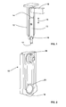
Figure 1 is a schematic a groove cutting tool according to an exemplary embodiment of the disclosure; -
Figure 2 is an exploded view of a slidable holder of the groove cutting tool ofFig. 1 ; and -
Figure 3 is an exploded view of a connection between the output pinion and blade of the groove cutting tool ofFig. 1 - Exemplary embodiments of the present disclosure are now described with references to the drawings, wherein like reference numerals are used to refer to like elements throughout. In the following description, for purposes of explanation, numerous specific details are set forth to provide a thorough understanding of the disclosure. However, the present disclosure may be practiced without these specific details, and is not limited to the exemplary embodiment disclosed herein.
- An exemplary embodiment of a
groove cutting tool 10 shown inFig. 1 has abody 12 in which is slidable mounted aholder 13. - The sliding mounting of the
holder 13 makes it possible to finely adjust the distance of the tool to a cutting surface. This adjustment may be made automatically with the assistance of sensor, by means of an adjustment mechanism such as a gear and/or motor or else my manual means, including the use of adjustment pins ( not shown) to fix the relative slidable position of theholder 13 to thebody 12 - In an exemplary embodiment shown in
Fig. 1 theholder 13 has a first end at which ablade 16 is mounted and a second end, distal, in aslidable direction 15 of the holder from the first end, at which adrive pinion 20, located towards the second end, is located. - The
drive pinion 20 is configured to be in rotational communication with the blade. In an exemplary embodiment shown inFig. 2 this is achieved by theholder 13 additionally having anoutput pinion 22 attached to theblade 16 wherein thedrive pinion 20 is in rotational communication with theoutput pinion 22. In an exemplary embodiment, this is achieved by a belt or chain between thedrive pinion 20 and theoutput pinion 22. In another not shown exemplary embodiment, thedrive pinion 20 and theoutput pinion 22 are connected by gears. The distal, that is non concentric, location of thedrive 18 from theoutput pinion 22 makes it possible to minimise the thickness of thegroove cutting tool 10 at theblade 16 end of thegroove cutting tool 10 enabling the tool to be used between turbine rotor blades without removal of the blades. - In an exemplary embodiment shown in
Fig. 1 , theblade 16 has ablade diameter 17 and slot has awidth 15 in a direction perpendicular to theslidable direction 15 and parallel to the blade wherein the blade diameter is less than or equal to thewidth 14. Not only does this enable slidable retraction of theblade 16 into theholder 13 but also makes it possible to shield theblade 16 so that only a portion of theblade 16 is exposed. This may have the advantage of increase personnel safety. - In an exemplary embodiment shown in
Fig. 3 , thegroove cutting tool 10 has ashaft 24 mounted to and extending perpendicular from theblade 16. Abearing 28 is additionally mounted on theshaft 24. Theoutput pinion 22 has a cavity in which theshaft 24 extends such that theoutput pinion 22 is connected to theshaft 24 in the cavity while thebearing 28 is at least partially located within the cavity. A portion of theholder 13 additionally extends to act as a second fixing point for thebearing 28. In this way, thebearing 28 is fixed between the portion of theholder 13 and theshaft 24 so as to enable rotation relative to theholder 13, as a unit, of theshaft 24, theoutput pinion 22 and theblade 16. This configuration provides an additional opportunity to minimise the thickness of the tool at theblade 16 end of thegroove cutting tool 10. - In an exemplary embodiment shown in
Fig. 3 theoutput pinion 22 is fixed to theshaft 24 by means of a plurality oftransmission bolts 26 so as to provide a compact and thin yet reliable fixing means. The fixing of theshaft 24 to theoutput pinion 22 is not, however, limited to this means and may be fixed by other known means including screw means and/or by shrink fit. - Although the disclosure has been herein shown and described in what is conceived to be the most practical exemplary embodiment the present disclosure can be embodied in other specific. The presently disclosed embodiments are therefore considered in all respects to be illustrative and not restricted. The scope of the disclosure is indicated by the appended claims rather that the foregoing description and all changes that come within the meaning and range and equivalences thereof are intended to be embraced therein.
-
- 10
- groove cutting tool
- 12
- body
- 13
- holder
- 14
- width
- 15
- slidable direction
- 16
- blade
- 17
- blade diameter
- 18
- drive
- 20
- drive pinion
- 22
- output pinion
- 24
- shaft
- 26
- transmission bolt
- 28
- bearing
Claims (5)
- A groove cutting tool (10) comprising:a body (12); anda holder (13) slidable mounted in the body (12), the holder (13) having:a first end;a blade (16) mounted at the first end; anda second end, distal, in a slidable direction (15) of the holder (13), from the first end,characterised by a drive pinion (20), located towards the second end, configured to be in rotational communication with the blade (16).
- The groove cutting tool (10) of claim 1 wherein the blade (16) has a blade (16) diameter and the holder (13) has a width (14) in a direction perpendicular to the slidable direction (15) and parallel to the blade (16), wherein the blade (16) diameter is less than or equal to the width (14).
- The groove cutting tool (10) of claim 1 or 2 further comprising:a shaft (24) mounted to and extending perpendicular from the blade (16);a bearing (28) mounted on the shaft (24);an output pinion (22) with a cavity, wherein the shaft (24) extends into the cavity and is fixed to the output pinion (22) within the cavity;a bearing (28) mounted on the shaft (24) in the cavity; anda portion of the holder (13) extending into the cavity such that the bearing (28) is fixed between the portion and the shaft (24) so as to enable rotation relative to the holder (13), as a unit, of the shaft (24), the output pinion (22) and the blade (16).
- The groove cutting tool (10) of claim 3 wherein the output pinion (22) is fixed to the shaft (24) by at least one transmission bolt (26).
- The groove cutting tool (10) of any one of claims 1 to 4 further comprising a drive (18) directly mounted on the drive pinion (20) and configured to rotate the drive pinion (20) relative to the holder (13).
Priority Applications (2)
| Application Number | Priority Date | Filing Date | Title |
|---|---|---|---|
| EP15154010.1A EP3053683A1 (en) | 2015-02-05 | 2015-02-05 | Groove cutting tool |
| US15/015,620 US10137512B2 (en) | 2015-02-05 | 2016-02-04 | Groove cutting tool |
Applications Claiming Priority (1)
| Application Number | Priority Date | Filing Date | Title |
|---|---|---|---|
| EP15154010.1A EP3053683A1 (en) | 2015-02-05 | 2015-02-05 | Groove cutting tool |
Publications (1)
| Publication Number | Publication Date |
|---|---|
| EP3053683A1 true EP3053683A1 (en) | 2016-08-10 |
Family
ID=52468896
Family Applications (1)
| Application Number | Title | Priority Date | Filing Date |
|---|---|---|---|
| EP15154010.1A Withdrawn EP3053683A1 (en) | 2015-02-05 | 2015-02-05 | Groove cutting tool |
Country Status (2)
| Country | Link |
|---|---|
| US (1) | US10137512B2 (en) |
| EP (1) | EP3053683A1 (en) |
Cited By (1)
| Publication number | Priority date | Publication date | Assignee | Title |
|---|---|---|---|---|
| CN111761109A (en) * | 2020-07-06 | 2020-10-13 | 南京宁源智能仪表有限公司 | A device for processing grooves inside and outside of an opening of a water meter watch case |
Citations (8)
| Publication number | Priority date | Publication date | Assignee | Title |
|---|---|---|---|---|
| DE215065C (en) * | ||||
| FR695607A (en) * | 1930-05-14 | 1930-12-18 | Tautant Dupau | Tool for milling flutes of tapered bores |
| JPH02303705A (en) * | 1989-05-16 | 1990-12-17 | Akebono Brake Ind Co Ltd | Exclusive milling machine for disc brake |
| DE4436239A1 (en) * | 1994-10-11 | 1996-04-18 | Rudolf Hildebrand | System for cutting slots in plastic tubes |
| US20050011924A1 (en) * | 2003-07-15 | 2005-01-20 | Yasuo Momose | Machining apparatus for forming cracking slot for connecting rod |
| US20060191393A1 (en) * | 2005-02-25 | 2006-08-31 | Qingdao D&D Electro Mechanical Technologies Co., Ltd. | Blade driving mechanism for a table saw |
| WO2011095823A1 (en) * | 2010-02-04 | 2011-08-11 | National Oilwell Varco L.P. | Stator manufacturing method and whirling cutter device |
| US8276488B2 (en) | 2007-02-01 | 2012-10-02 | Self Leveling Machines, Inc. | Boring machine for turbine casings |
Family Cites Families (3)
| Publication number | Priority date | Publication date | Assignee | Title |
|---|---|---|---|---|
| US3771894A (en) * | 1972-09-25 | 1973-11-13 | Gen Motors Corp | Circular arc groove cutting machine |
| US5125299A (en) * | 1990-05-10 | 1992-06-30 | Climax Portable Machine Tools, Inc. | Portable machine tool |
| JPH11179614A (en) * | 1997-10-15 | 1999-07-06 | Komatsu Koki Kk | Compound work device and work method therefor |
-
2015
- 2015-02-05 EP EP15154010.1A patent/EP3053683A1/en not_active Withdrawn
-
2016
- 2016-02-04 US US15/015,620 patent/US10137512B2/en active Active
Patent Citations (8)
| Publication number | Priority date | Publication date | Assignee | Title |
|---|---|---|---|---|
| DE215065C (en) * | ||||
| FR695607A (en) * | 1930-05-14 | 1930-12-18 | Tautant Dupau | Tool for milling flutes of tapered bores |
| JPH02303705A (en) * | 1989-05-16 | 1990-12-17 | Akebono Brake Ind Co Ltd | Exclusive milling machine for disc brake |
| DE4436239A1 (en) * | 1994-10-11 | 1996-04-18 | Rudolf Hildebrand | System for cutting slots in plastic tubes |
| US20050011924A1 (en) * | 2003-07-15 | 2005-01-20 | Yasuo Momose | Machining apparatus for forming cracking slot for connecting rod |
| US20060191393A1 (en) * | 2005-02-25 | 2006-08-31 | Qingdao D&D Electro Mechanical Technologies Co., Ltd. | Blade driving mechanism for a table saw |
| US8276488B2 (en) | 2007-02-01 | 2012-10-02 | Self Leveling Machines, Inc. | Boring machine for turbine casings |
| WO2011095823A1 (en) * | 2010-02-04 | 2011-08-11 | National Oilwell Varco L.P. | Stator manufacturing method and whirling cutter device |
Cited By (2)
| Publication number | Priority date | Publication date | Assignee | Title |
|---|---|---|---|---|
| CN111761109A (en) * | 2020-07-06 | 2020-10-13 | 南京宁源智能仪表有限公司 | A device for processing grooves inside and outside of an opening of a water meter watch case |
| CN111761109B (en) * | 2020-07-06 | 2021-06-18 | 南京宁源智能仪表有限公司 | Water meter case opening inside and outside groove machining device |
Also Published As
| Publication number | Publication date |
|---|---|
| US10137512B2 (en) | 2018-11-27 |
| US20160228957A1 (en) | 2016-08-11 |
Similar Documents
| Publication | Publication Date | Title |
|---|---|---|
| EP2125273B1 (en) | Boring machine for turbine casings | |
| EP2187506A1 (en) | Wind power turbine for producing electric energy | |
| TWI611863B (en) | Spindle assembly | |
| CN113874601A (en) | Method for adjusting seal clearance of steam turbine and steam turbine | |
| EP1918524A3 (en) | Fan rub strip in situ machining system and method | |
| WO2011101224A1 (en) | Electrical drive unit | |
| US9261101B2 (en) | Fan housing for ram air fan | |
| EP2679826A1 (en) | Impeller, rotor comprising same, and impeller manufacturing method | |
| US5181308A (en) | Method for installing annular seals | |
| EP3153266B1 (en) | Tube cutting device having conical fitting member to cut tube of waste steam generator and cutting method | |
| US10137512B2 (en) | Groove cutting tool | |
| EP3184220A1 (en) | Portable milling tool with method for turbomachine milling | |
| CN102917824B (en) | Method for machining grooves in a turbomachine turbine disc | |
| US9162329B2 (en) | Method for removing an inner casing from a machine | |
| EP2955329A1 (en) | Integrally formed rotor assembly with shaft and blisks | |
| EP3194115B1 (en) | High speed spindle | |
| US9200516B2 (en) | Turbomachine rotor having dovetail slot and method of machining | |
| BRPI0509098A (en) | rotary electric machine | |
| JP7067423B2 (en) | Motor built-in spindle device | |
| EP3575023B1 (en) | Inner shaft machining tool and method | |
| CN105127517A (en) | Built-in cutting mechanism and a built-in cutting process | |
| DE102015218521A1 (en) | Electric machine | |
| CN103418803A (en) | End cover machining mechanism of self-driving chuck double knife holders | |
| US20110197734A1 (en) | Whirling cutting device | |
| CN105782016A (en) | Oil pump rotor |
Legal Events
| Date | Code | Title | Description |
|---|---|---|---|
| PUAI | Public reference made under article 153(3) epc to a published international application that has entered the european phase |
Free format text: ORIGINAL CODE: 0009012 |
|
| AK | Designated contracting states |
Kind code of ref document: A1 Designated state(s): AL AT BE BG CH CY CZ DE DK EE ES FI FR GB GR HR HU IE IS IT LI LT LU LV MC MK MT NL NO PL PT RO RS SE SI SK SM TR |
|
| AX | Request for extension of the european patent |
Extension state: BA ME |
|
| RAP1 | Party data changed (applicant data changed or rights of an application transferred) |
Owner name: GENERAL ELECTRIC TECHNOLOGY GMBH |
|
| 17P | Request for examination filed |
Effective date: 20170210 |
|
| RBV | Designated contracting states (corrected) |
Designated state(s): AL AT BE BG CH CY CZ DE DK EE ES FI FR GB GR HR HU IE IS IT LI LT LU LV MC MK MT NL NO PL PT RO RS SE SI SK SM TR |
|
| STAA | Information on the status of an ep patent application or granted ep patent |
Free format text: STATUS: THE APPLICATION IS DEEMED TO BE WITHDRAWN |
|
| 18D | Application deemed to be withdrawn |
Effective date: 20190903 |