EP3052721B1 - Deployable flexible flood mitigation device - Google Patents
Deployable flexible flood mitigation device Download PDFInfo
- Publication number
- EP3052721B1 EP3052721B1 EP14852609.8A EP14852609A EP3052721B1 EP 3052721 B1 EP3052721 B1 EP 3052721B1 EP 14852609 A EP14852609 A EP 14852609A EP 3052721 B1 EP3052721 B1 EP 3052721B1
- Authority
- EP
- European Patent Office
- Prior art keywords
- door
- gate
- flood
- flexible
- deadman
- Prior art date
- Legal status (The legal status is an assumption and is not a legal conclusion. Google has not performed a legal analysis and makes no representation as to the accuracy of the status listed.)
- Active
Links
Images
Classifications
-
- E—FIXED CONSTRUCTIONS
- E04—BUILDING
- E04H—BUILDINGS OR LIKE STRUCTURES FOR PARTICULAR PURPOSES; SWIMMING OR SPLASH BATHS OR POOLS; MASTS; FENCING; TENTS OR CANOPIES, IN GENERAL
- E04H9/00—Buildings, groups of buildings or shelters adapted to withstand or provide protection against abnormal external influences, e.g. war-like action, earthquake or extreme climate
- E04H9/14—Buildings, groups of buildings or shelters adapted to withstand or provide protection against abnormal external influences, e.g. war-like action, earthquake or extreme climate against other dangerous influences, e.g. tornadoes, floods
- E04H9/145—Floods
-
- E—FIXED CONSTRUCTIONS
- E06—DOORS, WINDOWS, SHUTTERS, OR ROLLER BLINDS IN GENERAL; LADDERS
- E06B—FIXED OR MOVABLE CLOSURES FOR OPENINGS IN BUILDINGS, VEHICLES, FENCES OR LIKE ENCLOSURES IN GENERAL, e.g. DOORS, WINDOWS, BLINDS, GATES
- E06B9/00—Screening or protective devices for wall or similar openings, with or without operating or securing mechanisms; Closures of similar construction
- E06B9/02—Shutters, movable grilles, or other safety closing devices, e.g. against burglary
- E06B9/08—Roll-type closures
- E06B9/11—Roller shutters
- E06B9/13—Roller shutters with closing members of one piece, e.g. of corrugated sheet metal
-
- E—FIXED CONSTRUCTIONS
- E06—DOORS, WINDOWS, SHUTTERS, OR ROLLER BLINDS IN GENERAL; LADDERS
- E06B—FIXED OR MOVABLE CLOSURES FOR OPENINGS IN BUILDINGS, VEHICLES, FENCES OR LIKE ENCLOSURES IN GENERAL, e.g. DOORS, WINDOWS, BLINDS, GATES
- E06B9/00—Screening or protective devices for wall or similar openings, with or without operating or securing mechanisms; Closures of similar construction
- E06B2009/007—Flood panels
-
- E—FIXED CONSTRUCTIONS
- E06—DOORS, WINDOWS, SHUTTERS, OR ROLLER BLINDS IN GENERAL; LADDERS
- E06B—FIXED OR MOVABLE CLOSURES FOR OPENINGS IN BUILDINGS, VEHICLES, FENCES OR LIKE ENCLOSURES IN GENERAL, e.g. DOORS, WINDOWS, BLINDS, GATES
- E06B9/00—Screening or protective devices for wall or similar openings, with or without operating or securing mechanisms; Closures of similar construction
- E06B9/56—Operating, guiding or securing devices or arrangements for roll-type closures; Spring drums; Tape drums; Counterweighting arrangements therefor
- E06B9/58—Guiding devices
- E06B2009/588—Sealings for guides
-
- Y—GENERAL TAGGING OF NEW TECHNOLOGICAL DEVELOPMENTS; GENERAL TAGGING OF CROSS-SECTIONAL TECHNOLOGIES SPANNING OVER SEVERAL SECTIONS OF THE IPC; TECHNICAL SUBJECTS COVERED BY FORMER USPC CROSS-REFERENCE ART COLLECTIONS [XRACs] AND DIGESTS
- Y02—TECHNOLOGIES OR APPLICATIONS FOR MITIGATION OR ADAPTATION AGAINST CLIMATE CHANGE
- Y02A—TECHNOLOGIES FOR ADAPTATION TO CLIMATE CHANGE
- Y02A50/00—TECHNOLOGIES FOR ADAPTATION TO CLIMATE CHANGE in human health protection, e.g. against extreme weather
Definitions
- the present invention relates to a Flexible Flood Mitigation Device system that is scalable in size, shape, and orientation to a wide variety of openings.
- the invention can be used to seal part or all of an opening from flood water or other fluid threats.
- Flooding events can be precipitated by natural and manmade inputs. These events can be particularly challenging for buildings and infrastructure located at or near a body of water. Transportation systems or buildings in these areas that are below the normal waterline are particularly vulnerable. Severe storms with high tidal surges or flash floods, rising sea levels, and seismic activity are some of the challenges posed by nature. Accidents, terrorism, and mechanical failures are manmade threats that can cause flooding, or magnify flooding from natural events.
- Textile & membrane based Flexible Flood Mitigation Devices offer significant benefits over the rigid devices.
- Flood mitigation systems are disclosed in WO 2011/159146 , GB 2379948 , US 2005/163570 , WO 2012/169877 , WO 2013/069574 .
- Most notable is the ability to pack the material into a small volume for storage. This not only allows the Flexible Flood Mitigation Device to be stored in, a small volume that is easily fit into existing spaces, but it minimizes the modifications required on the infrastructure to install it.
- the membrane door itself is shaped to minimize stress in the door (governed by pressure multiplied by radius of curvature). The door is attached to tracks with a "deadman" which guides deployment and also seals the door when the door is tensioned.
- the deadman is an assembly which is larger than the slot in the guide rail and therefore prevents extraction when the door is tensioned by water pressure.
- the base of the membrane door has a plate to guide deployment and support an elastomeric seal that seals that edge of the door.
- the membrane door can be packed via rolling or folding, and can be deployed manually or automatically from a spool with a motor.
- the design has very few moving parts and requires little to no regular maintenance, and is survivable in many harsh environments.
- the Flexible Flood Mitigation Device is deployable door or wail that leverages the unique advantages of textile & membrane materials to advance the state of the art in flood mitigation devices.
- a deployable flood-gate comprising: a flexible door comprising at least one member selected from the group consisting of a textile, a membrane and combinations thereof; a rigid perimeter structure comprising a guide rail that guides deployment of the door; the perimeter structure further comprising a track that supports loading on and sealing of the flexible door against hydrostatic pressure; the track comprising an opening to permit the flexible door member to extend through the opening; said door further comprising an integral edge sealing section provided interiorly of the track and of a size larger than the opening, such that the integral edge sealing section cannot be pulled out of the track through the opening, which integral edge sealing section is deformable and presents a broader sealing area in direct contact with the track than the sealing area presented by the flexible door member itself; and, a storage container for the flexible door with deployment and retraction mechanisms; wherein at least some of the perimeter of the flexible door is comprised of the integral edge sealing section in the form of a flexible deadman, which deadman is integrally connected to structural support and pressure retention layers of the flexible door, and which dead
- the Flexible Flood Mitigation Device is comprised of a textile & membrane door, side rails for deployment and attachment of the door, a base plate for guiding deployment and sealing, a spool or other guide to facilitate stowage & deployment, and a container.
- the system may also include electric motors and mechanisms, or manually operated devices, to facilitate or assist deployment & retraction.
- the textile door is rolled or folded into the container and stowed until a potential flooding event is identified. At this time, the container is opened and the door is deployed such that its installation portal is blocked and can prevent the passage of water under significant hydrostatic pressure (from zero to tens of metres (feet) of pressure head).
- the deadman attachment of the textile door to a track inside the guide rail provides the seal via compression of the deadman when the door is tensioned with pressure.
- the deadman is also a textile and membrane assembly and is constructed such that tension of the door pulls it into the sliding rail causing it to conform to its shape and present a broad sealing area to the guide rail. The deadman is larger than the opening in the guide rail and therefore cannot be pulled out.
- the door can be positioned vertically or horizontally.
- the container can be located on any side of a vertical door (above, below, or on a side), with the guide rails extending perpendicular to the container. When placed horizontally, the container can be placed wherever is convenient. In the case of a subway stairwell, it can be located inside the top stair or at the opposite end of the opening away from the top stair.
- a textile & membrane door is flexible and the guide rails can be angled, curved, or formed to fit around objects. This can further reduce infrastructure modifications during installation, or enhance functionality of the system. For example, if the door and deadman assembly were trapezoidal in shape, and the guide rails and support frame were a similar trapezoidal shape, then the two would provide an interference fit at the final portion of deployment travel thus sealing and tensioning the deadman assembly. Deployable clamping devices can also be used to compress and seal the deadman assembly as a primary means of sealing or for redundancy in the tensioned sealing approach if desirable.
- the door can be loaded from either side thus increasing functionality over standard flood gates. This is possible because of how the deadman interfaces with the guide rail. Furthermore, it is possible to construct a textile & membrane flood gate door such that the loads imparted back into the supporting structure are either longitudinal, vertical, or a combination of both. This can be beneficial in the design of structural reinforcements which dictate the level of infrastructure modification required for installation of a flood gate.
- a second aspect of the disclosure is the use of a similar but less structural version to be used in the containment of smoke from fire, chemical or biological agents, or other transient media.
- the functionality of the system is the same, but the forces on the system are lower with a smaller delta pressure across the boundary so thinner materials can be used.
- n Another expression of the disclosure n is a separable textile & membrane door assembly that can be stored remotely from its point of use. It can be transported to its use location when needed and installed into a preinstalled support frame. The frame would be able to accept the deadman assembly through clamping, or sliding an intermittent deadman into segmented slots. This approach may be of interest for oddly shaped tunnels/shafts such as a circular underwater subway tunnel where excavation of the infrastructure is not possible, or encroachment upon the interior space is not allowable.
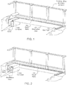
- FIG, 1 illustrates perspective views of a Flexible Flood Mitigation Device with the door in the deployed position 100 according to an embodiment of the present invention.
- FIG. 2 illustrates the Flexible Flood Mitigation Device 100 in its stowed condition
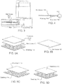
- FIGS. 3 through 5A-5D respectively, illustrate detailed views of critical features of the Flexible Flood Mitigation Device 100.
- the Flexible Flood Mitigation Device is also referred to as the Flex-Gate.
- the Flexible Flood Mitigation Device 100 is comprised of a textile & membrane door 101, guide rails 102, an end plate 103, a spool 104, and a container 105.
- the door 101 is movable through the guide rails 102 and can be moved from a stowed to a deployed position and visa-versa.
- the door 101 When the Flexible Flood Mitigation Device 100 is activated as shown in FIG. 1 , the door 101 is positioned such that it can hold back hydrostatic pressure from zero to tens of metres (feet) of hydrostatic pressure head of water or other fluids.
- the Flexible Flood Mitigation Device When the Flexible Flood Mitigation Device is stowed as shown in FIG. 2 the intended traffic (people, air, automobiles, trains, etc.) can pass through the opening.
- the Flexible Flood Mitigation Device 100 can be sized and shaped to fit any opening.
- the membrane door can also be configured to conform to features in a tunnel, such as conduits on a wall, by having curved guide rails 102 that conform to the feature.
- the membrane door 101 is manufactured to be concave such that the stresses in the door 101 and the guide rails 102 are minimized.
- the membrane door 101 has a deadman 106 feature on two sides of its perimeter that engage the guide rails 102 to facilitate deployment and sealing.
- the end plate 103 has sealing features 107 on any of its exposed faces to provide a seal against the mating surface when the Flexible Flood Mitigation Device is closed and a fluid impinges upon it.
- the guide rails 102 incorporated a feature 107 near the end where the end plate 103 comes to rest to engage and seal the deadman 106 on the membrane door 101.
- the feature 107 applies tension to the deadman 106 in this area to seal the deadman 106 in the guide rails 102 which are unable to be tensioned when the membrane door 101 is engaged with water because the end plate is rigid.
- the end plate 103 is then locked into place with a latching mechanism 109.
- the latching mechanism 109 can take many forms and could be located in various areas on the assembly.
- the end of the membrane door 101 that is opposite the end plate 103 can be terminated in a number of ways.
- the method shown here is to include a deadman 106 as on the sides of the membrane door 101.
- clamping, fixed termination in the spool 104 or container 105, or a termination similar to the end plate 103 end is also possible.
- sealing in this area will not be necessary.
- the membrane door 101 can be stowed in a number of ways including rolling or folding. If rolling is selected, a spool 104 can be used to control the packing of the material and assist deployment/ retraction. If a more compact assembly is required, then the material can be stored without the aid of a spool 104 via folding.
- the spool 104 can be motorized or equipped with a manual crank for deployment and retraction.
- FIG.3 illustrates the interface of the deadman 106 with the guide rails 102 during deployment when the membrane door 101 is un-tensioned, and when it is tensioned.
- the deadman 106 is un-tensioned during deployment to eliminate friction and reduce deployment forces.
- the deadman 106 or guide rails 102 may have coatings or finishes to reduce friction during deployment.
- the deadman 106 conforms to the shape of the guide rails 102 and provides an enlarged seal area compared to cable or rod constructions because of it is manufactured with compliant materials, such as textile assemblies including ropes and webbings.
- the deadman 106 does not require any lubricant when used in this way.
- a seal 107 is positioned adjacent deadman 106 .
- the deadman 106 is comprised of an inner core 110, a membrane door webbing 114, membrane door membrane 115, and a deadman protective covering.
- the inner core 110 provides strength and a geometric feature that cannot be compressed through the slot in the guide rails 102 .
- the membrane door webbing 114 is an extension of the webbing structure of the membrane door 101. The webbings wrap around the inner core 110 and are sewn to create a loop. This junction provides a path for loads from the membrane door 101 to the guide rails 102.
- the membrane door membrane 115 is an extension of the impervious layer of the membrane door 101. The membrane door membrane wraps around the inner core 110 to extend the seal from the membrane door 101 into the guide rails 102.
- An optional protective covering 116 ( Fig. 5A ) may be added to add resiliency to the assembly or enhance sealing by nature of its compliance.
- FIGS. 5A-5D illustrates the parts of the membrane door in the various embodiments according to the invention.
- the webbing 114 ( Figs. 5A, 5C, 5D ) is the structural component of the membrane door 101. It is manufactured by weaving webbings together to create a macro-fabric. Other flat material sections can be substituted for webbings. The interweaving of the webbings provides structural resiliency to the assembly because the assembly will not come apart, even if one webbing is fully severed. The friction between the webbings prevents webbing shift in this event.
- the webbings 114 can be left unconnected, or they can be joined at regular intervals, via stitching, sealing, bonding or some similar activity.
- the webbing 114 can be coated or impregnated with plastic or elastomeric coatings, or it can be uncoated. Joining the webbings 114 prevents gaps in the webbing that can leave the membrane 115 exposed to potential damage from debris, or unequal loading due when the assembly is tensioned.
- the webbings 114 can be assembled in such a way so as to transmit the loads in the membrane door 101 either axially or longitudinally, or a combination of both. This is accomplished by lengthening the webbings in the direction you wish to prevent load transmission.
- the membrane 115 is positioned adjacent to the webbing 114 assembly and is oversized to ensure load transfer in the webbing 114 assembly.
- the membrane 115 prevents water transmission past the membrane door 101.
- the membrane can be any formed from a number of materials, including polymer coated fabrics, elastomeric sheets, plastic films, etc.
- a protective layer 116 ( Fig. 5A ) can be added to the assembly between the webbing 114 layer and the membrane 115 layer to provide additional structural redundancy and resiliency, This can be desirable if and there is any potential for impact from floating debris or other threats.
- the protective layer can also be applied on the water side in such a way as to protect the membrane 115 itself.
Landscapes
- Engineering & Computer Science (AREA)
- Structural Engineering (AREA)
- Architecture (AREA)
- Civil Engineering (AREA)
- Business, Economics & Management (AREA)
- Emergency Management (AREA)
- Environmental & Geological Engineering (AREA)
- Special Wing (AREA)
- General Engineering & Computer Science (AREA)
- Buildings Adapted To Withstand Abnormal External Influences (AREA)
- Specific Sealing Or Ventilating Devices For Doors And Windows (AREA)
- Mechanical Engineering (AREA)
Description
- The present invention relates to a Flexible Flood Mitigation Device system that is scalable in size, shape, and orientation to a wide variety of openings. The invention can be used to seal part or all of an opening from flood water or other fluid threats.
- Flooding events can be precipitated by natural and manmade inputs. These events can be particularly challenging for buildings and infrastructure located at or near a body of water. Transportation systems or buildings in these areas that are below the normal waterline are particularly vulnerable. Severe storms with high tidal surges or flash floods, rising sea levels, and seismic activity are some of the challenges posed by nature. Accidents, terrorism, and mechanical failures are manmade threats that can cause flooding, or magnify flooding from natural events.
- Many subway and vehicular tunnels that operate below waterline around the world have experienced flooding. Hurricane Sandy was particularly devastating to New York City in 2012 because a significant portion of the subway system was flooded and economic losses were unprecedented. Water entrance points included subway portals, stairwell entrance points, ventilation shafts, emergency exits, and elevator shafts. Vehicular tunnels were also flooded, as well as many buildings. This was one of the worst flooding events in history, but it was just one in a string of events in subway systems in major cities around the world.
- There are many types of flood mitigation systems available commercially. This includes Flexible Flood Mitigation Devices, stop logs, and flood doors. These are designed to withstand significant hydrostatic pressures (up to tens of metres (feet) of water) and do so with rigid components and mechanisms to deploy them. These systems often require significant modification to the infrastructure during installation, a considerable amount of storage space, frequent maintenance, and are costly to install because of the impact on the system Because of this, they are often found to be unacceptable in transit and other applications.
- Textile & membrane based Flexible Flood Mitigation Devices offer significant benefits over the rigid devices. Flood mitigation systems are disclosed in
WO 2011/159146 ,GB 2379948 US 2005/163570 ,WO 2012/169877 ,WO 2013/069574 . Most notable is the ability to pack the material into a small volume for storage. This not only allows the Flexible Flood Mitigation Device to be stored in, a small volume that is easily fit into existing spaces, but it minimizes the modifications required on the infrastructure to install it. The membrane door itself is shaped to minimize stress in the door (governed by pressure multiplied by radius of curvature). The door is attached to tracks with a "deadman" which guides deployment and also seals the door when the door is tensioned. The deadman is an assembly which is larger than the slot in the guide rail and therefore prevents extraction when the door is tensioned by water pressure. The base of the membrane door has a plate to guide deployment and support an elastomeric seal that seals that edge of the door. The membrane door can be packed via rolling or folding, and can be deployed manually or automatically from a spool with a motor. The design has very few moving parts and requires little to no regular maintenance, and is survivable in many harsh environments. - The Flexible Flood Mitigation Device is deployable door or wail that leverages the unique advantages of textile & membrane materials to advance the state of the art in flood mitigation devices.
- There is provided in the present invention a deployable flood-gate comprising: a flexible door comprising at least one member selected from the group consisting of a textile, a membrane and combinations thereof; a rigid perimeter structure comprising a guide rail that guides deployment of the door; the perimeter structure further comprising a track that supports loading on and sealing of the flexible door against hydrostatic pressure; the track comprising an opening to permit the flexible door member to extend through the opening; said door further comprising an integral edge sealing section provided interiorly of the track and of a size larger than the opening, such that the integral edge sealing section cannot be pulled out of the track through the opening, which integral edge sealing section is deformable and presents a broader sealing area in direct contact with the track than the sealing area presented by the flexible door member itself; and, a storage container for the flexible door with deployment and retraction mechanisms; wherein at least some of the perimeter of the flexible door is comprised of the integral edge sealing section in the form of a flexible deadman, which deadman is integrally connected to structural support and pressure retention layers of the flexible door, and which deadman is deformable and presents a broader sealing area in direct contact with the track than the sealing area presented by the flexible door member itself.
- The Flexible Flood Mitigation Device is comprised of a textile & membrane door, side rails for deployment and attachment of the door, a base plate for guiding deployment and sealing, a spool or other guide to facilitate stowage & deployment, and a container. The system may also include electric motors and mechanisms, or manually operated devices, to facilitate or assist deployment & retraction.
- The textile door is rolled or folded into the container and stowed until a potential flooding event is identified. At this time, the container is opened and the door is deployed such that its installation portal is blocked and can prevent the passage of water under significant hydrostatic pressure (from zero to tens of metres (feet) of pressure head). The deadman attachment of the textile door to a track inside the guide rail provides the seal via compression of the deadman when the door is tensioned with pressure. The deadman is also a textile and membrane assembly and is constructed such that tension of the door pulls it into the sliding rail causing it to conform to its shape and present a broad sealing area to the guide rail. The deadman is larger than the opening in the guide rail and therefore cannot be pulled out.
- The door can be positioned vertically or horizontally. The container can be located on any side of a vertical door (above, below, or on a side), with the guide rails extending perpendicular to the container. When placed horizontally, the container can be placed wherever is convenient. In the case of a subway stairwell, it can be located inside the top stair or at the opposite end of the opening away from the top stair.
- Another feature of a textile & membrane door is that it is flexible and the guide rails can be angled, curved, or formed to fit around objects. This can further reduce infrastructure modifications during installation, or enhance functionality of the system. For example, if the door and deadman assembly were trapezoidal in shape, and the guide rails and support frame were a similar trapezoidal shape, then the two would provide an interference fit at the final portion of deployment travel thus sealing and tensioning the deadman assembly. Deployable clamping devices can also be used to compress and seal the deadman assembly as a primary means of sealing or for redundancy in the tensioned sealing approach if desirable.
- It is possible that the door can be loaded from either side thus increasing functionality over standard flood gates. This is possible because of how the deadman interfaces with the guide rail. Furthermore, it is possible to construct a textile & membrane flood gate door such that the loads imparted back into the supporting structure are either longitudinal, vertical, or a combination of both. This can be beneficial in the design of structural reinforcements which dictate the level of infrastructure modification required for installation of a flood gate.
- A second aspect of the disclosure is the use of a similar but less structural version to be used in the containment of smoke from fire, chemical or biological agents, or other transient media. The functionality of the system is the same, but the forces on the system are lower with a smaller delta pressure across the boundary so thinner materials can be used.
- Another expression of the disclosure n is a separable textile & membrane door assembly that can be stored remotely from its point of use. It can be transported to its use location when needed and installed into a preinstalled support frame. The frame would be able to accept the deadman assembly through clamping, or sliding an intermittent deadman into segmented slots. This approach may be of interest for oddly shaped tunnels/shafts such as a circular underwater subway tunnel where excavation of the infrastructure is not possible, or encroachment upon the interior space is not allowable.
-
-
FIG. 1 illustrates the assembly as applied in a horizontal orientation, with the door deployed -
FIG. 2 illustrates the assembly as applied in a horizontal orientation, with the door stowed -
FIG. 3 illustrates the attachment of the fabric door to the frame, and sealing featureFIG. 4 illustrates the deadman -
FIGS. 5A-5D illustrates the various embodiments in construction of the fabric door -
FIG, 1 illustrates perspective views of a Flexible Flood Mitigation Device with the door in the deployed position 100 according to an embodiment of the present invention.FIG. 2 illustrates the Flexible Flood Mitigation Device 100 in its stowed condition,FIGS. 3 through 5A-5D respectively, illustrate detailed views of critical features of the Flexible Flood Mitigation Device 100. The Flexible Flood Mitigation Device is also referred to as the Flex-Gate. - As shown in
FIGS. 1 and 2 , the Flexible Flood Mitigation Device 100 is comprised of a textile &membrane door 101,guide rails 102, anend plate 103, aspool 104, and acontainer 105. - The
door 101 is movable through theguide rails 102 and can be moved from a stowed to a deployed position and visa-versa. When the Flexible Flood Mitigation Device 100 is activated as shown inFIG. 1 , thedoor 101 is positioned such that it can hold back hydrostatic pressure from zero to tens of metres (feet) of hydrostatic pressure head of water or other fluids. When the Flexible Flood Mitigation Device is stowed as shown inFIG. 2 the intended traffic (people, air, automobiles, trains, etc.) can pass through the opening. The Flexible Flood Mitigation Device 100 can be sized and shaped to fit any opening. The membrane door can also be configured to conform to features in a tunnel, such as conduits on a wall, by havingcurved guide rails 102 that conform to the feature. Themembrane door 101 is manufactured to be concave such that the stresses in thedoor 101 and theguide rails 102 are minimized. - The
membrane door 101 has adeadman 106 feature on two sides of its perimeter that engage theguide rails 102 to facilitate deployment and sealing. Theend plate 103 has sealingfeatures 107 on any of its exposed faces to provide a seal against the mating surface when the Flexible Flood Mitigation Device is closed and a fluid impinges upon it. The guide rails 102 incorporated afeature 107 near the end where theend plate 103 comes to rest to engage and seal thedeadman 106 on themembrane door 101. Thefeature 107 applies tension to thedeadman 106 in this area to seal thedeadman 106 in theguide rails 102 which are unable to be tensioned when themembrane door 101 is engaged with water because the end plate is rigid. Theend plate 103 is then locked into place with a latching mechanism 109. The latching mechanism 109 can take many forms and could be located in various areas on the assembly. - The end of the
membrane door 101 that is opposite theend plate 103 can be terminated in a number of ways. The method shown here is to include adeadman 106 as on the sides of themembrane door 101. However, clamping, fixed termination in thespool 104 orcontainer 105, or a termination similar to theend plate 103 end is also possible. In some cases where thecontainer 105 is placed above water level, sealing in this area will not be necessary. - The
membrane door 101 can be stowed in a number of ways including rolling or folding. If rolling is selected, aspool 104 can be used to control the packing of the material and assist deployment/ retraction. If a more compact assembly is required, then the material can be stored without the aid of aspool 104 via folding. Thespool 104 can be motorized or equipped with a manual crank for deployment and retraction. -
FIG.3 illustrates the interface of thedeadman 106 with theguide rails 102 during deployment when themembrane door 101 is un-tensioned, and when it is tensioned. Thedeadman 106 is un-tensioned during deployment to eliminate friction and reduce deployment forces. Thedeadman 106 orguide rails 102 may have coatings or finishes to reduce friction during deployment. Thedeadman 106 conforms to the shape of theguide rails 102 and provides an enlarged seal area compared to cable or rod constructions because of it is manufactured with compliant materials, such as textile assemblies including ropes and webbings. Thedeadman 106 does not require any lubricant when used in this way. Aseal 107 is positionedadjacent deadman 106. - As shown in
FIG. 4 , thedeadman 106 is comprised of aninner core 110, amembrane door webbing 114,membrane door membrane 115, and a deadman protective covering. Theinner core 110 provides strength and a geometric feature that cannot be compressed through the slot in the guide rails 102. Themembrane door webbing 114 is an extension of the webbing structure of themembrane door 101. The webbings wrap around theinner core 110 and are sewn to create a loop. This junction provides a path for loads from themembrane door 101 to the guide rails 102. Themembrane door membrane 115 is an extension of the impervious layer of themembrane door 101. The membrane door membrane wraps around theinner core 110 to extend the seal from themembrane door 101 into the guide rails 102. An optional protective covering 116 (Fig. 5A ) may be added to add resiliency to the assembly or enhance sealing by nature of its compliance. -
FIGS. 5A-5D illustrates the parts of the membrane door in the various embodiments according to the invention. The webbing 114 (Figs. 5A, 5C, 5D ) is the structural component of themembrane door 101. It is manufactured by weaving webbings together to create a macro-fabric. Other flat material sections can be substituted for webbings. The interweaving of the webbings provides structural resiliency to the assembly because the assembly will not come apart, even if one webbing is fully severed. The friction between the webbings prevents webbing shift in this event. Thewebbings 114 can be left unconnected, or they can be joined at regular intervals, via stitching, sealing, bonding or some similar activity. Thewebbing 114 can be coated or impregnated with plastic or elastomeric coatings, or it can be uncoated. Joining thewebbings 114 prevents gaps in the webbing that can leave themembrane 115 exposed to potential damage from debris, or unequal loading due when the assembly is tensioned. Thewebbings 114 can be assembled in such a way so as to transmit the loads in themembrane door 101 either axially or longitudinally, or a combination of both. This is accomplished by lengthening the webbings in the direction you wish to prevent load transmission. - The
membrane 115 is positioned adjacent to thewebbing 114 assembly and is oversized to ensure load transfer in thewebbing 114 assembly. Themembrane 115 prevents water transmission past themembrane door 101. The membrane can be any formed from a number of materials, including polymer coated fabrics, elastomeric sheets, plastic films, etc. - A protective layer 116 (
Fig. 5A ) can be added to the assembly between thewebbing 114 layer and themembrane 115 layer to provide additional structural redundancy and resiliency, This can be desirable if and there is any potential for impact from floating debris or other threats. The protective layer can also be applied on the water side in such a way as to protect themembrane 115 itself.
Claims (15)
- A deployable flood-gate comprising:a flexible door (101) comprising at least one member selected from the group consisting of a textile, a membrane (115) and combinations thereof;a rigid perimeter structure comprising a guide rail (102) that guides deployment of the door (101); the perimeter structure further comprising a track that supports loading and sealing of the door (101) against hydrostatic pressure, the track comprising an opening to permit the flexible door (101) member to extend through the opening;said door (101) further comprising an integral edge sealing section provided interiorly of the track and of a size larger than the opening, such that the integral edge sealing section cannot be pulled out of the track through the opening, which integral edge sealing section is deformable and presents a broader sealing area in direct contact with the track than the sealing area presented by the flexible door (101) member itself; anda storage container (105) for the door with deployment and retraction mechanisms, wherein at least some of the perimeter of the flexible door (101) is comprised of the integral edge sealing section in the form of a flexible deadman (106), which deadman (106) is integrally connected to structural support and pressure retention layers of the flexible door (101), and which deadman (106) is deformable and presents a broader sealing area in direct contact with the track than the sealing area presented by the flexible door (101) member itself.
- The deployable flood-gate of claim 1, wherein the flexible door (101) is comprised of multiple layers of material to provide structural support and pressure retention.
- The deployable flood-gate of claim 2, further comprising any one of the following:(i) wherein the flexible door (101) has a concave shape to reduce stress in the structure, optionally where the concave shape of the door (101) tensions and deforms the deadman (106) inside the guide rails (102) by reason of pressure;(ii) wherein the flexible door (101) is further comprised of at least one component selected from the group consisting of fabric, webbings (114), straps, belts, tapes and combinations thereof, for structural support;(iii) where the deadman can be compressed and sealed to the inside of the guide rails (102);iv) where the flexible nature of the multilayer door (101) facilitates rolling or folding of the door (101) for storage;(v) wherein the door (101) has a rigid plate at its ends to facilitate end sealing and be load bearing;(vi) wherein the door (101) can be manufactured so that load transfer to the perimeter frame can be parallel to the guide rails (102), perpendicular to the guide rails (102), or a combination of both.
- The deployable flood-gate of claim 3, comprising only the second alternative (ii) of claim 3, further comprising any one of the following:(i) wherein the at least one component selected from the group consisting of fabric, webbings (114), straps, belts, tapes and combinations thereof, are woven such that they provide damage tolerance via friction if a portion of them are damaged;(ii) wherein the at least one component selected from the group consisting of fabric, webbings (114), straps, belts, tapes and combinations thereof, are connected to one another by stitching, welding, bonding or combinations thereof;(iii) wherein one or more additional fabric layers is included in the flexible door (101) to provide resiliency or redundancy.
- The deployable flood-gate of claim 1, wherein the deadman (106) is comprised of a flexible rope, cable, or assembly of flexible material.
- The deployable flood-gate of claim 1, wherein the deadman (106) is integrally covered in an
impermeable material that deforms under pressure and seals against the guide rails (102). - The deployable flood-gate of claim 1, wherein the deadman (106) is comprised of flexible compliant materials that conform to the shape of the track and seals the flexible door (101).
- The deployable flood-gate of claim 1, wherein the track comprising the perimeter structure which guides deployment is shaped to capture the deadman (106) such that it cannot be pulled out when tensioned.
- The deployable flood-gate of claim 1, wherein the perimeter structure which guides deployment is manufactured from a rigid material and includes an integral compliant surface to aid in sealing.
- The deployable flood-gate of claim 1, wherein the deadman (106) provides a seal against hydrostatic pressure.
- The deployable flood-gate of claim 1, wherein the flood-gate can be challenged by a fluid from either side.
- The deployable flood-gate of claim 1, wherein the flood-gate can be positioned in any orientation.
- The deployable flood-gate of claim 1, wherein the deployment of the flood-gate can be manually operated.
- The deployable flood-gate of claim 1, wherein the flood-gate can be used to stop any fluid selected from at least one of the group consisting of liquids and gasses.
- The deployable flood-gate of claim 1, wherein the flexible door (101) can be deployed by attaching the door (101) to the guide rails (102).
Priority Applications (1)
| Application Number | Priority Date | Filing Date | Title |
|---|---|---|---|
| PL14852609T PL3052721T3 (en) | 2013-10-08 | 2014-10-01 | Deployable flexible flood mitigation device |
Applications Claiming Priority (2)
| Application Number | Priority Date | Filing Date | Title |
|---|---|---|---|
| US14/048,484 US9303423B2 (en) | 2013-10-08 | 2013-10-08 | Deployable flexible flood mitigation device |
| PCT/US2014/058657 WO2015054007A1 (en) | 2013-10-08 | 2014-10-01 | Deployable flexible flood mitigation device |
Publications (3)
| Publication Number | Publication Date |
|---|---|
| EP3052721A1 EP3052721A1 (en) | 2016-08-10 |
| EP3052721A4 EP3052721A4 (en) | 2017-03-15 |
| EP3052721B1 true EP3052721B1 (en) | 2018-08-15 |
Family
ID=52775807
Family Applications (1)
| Application Number | Title | Priority Date | Filing Date |
|---|---|---|---|
| EP14852609.8A Active EP3052721B1 (en) | 2013-10-08 | 2014-10-01 | Deployable flexible flood mitigation device |
Country Status (9)
| Country | Link |
|---|---|
| US (1) | US9303423B2 (en) |
| EP (1) | EP3052721B1 (en) |
| CN (1) | CN105793503B (en) |
| CA (1) | CA2927208C (en) |
| DK (1) | DK3052721T3 (en) |
| ES (1) | ES2695228T3 (en) |
| PL (1) | PL3052721T3 (en) |
| PT (1) | PT3052721T (en) |
| WO (1) | WO2015054007A1 (en) |
Families Citing this family (17)
| Publication number | Priority date | Publication date | Assignee | Title |
|---|---|---|---|---|
| GB2515291B (en) * | 2013-06-18 | 2015-09-09 | Simon S Mcnally | Stand-alone water defence apparatus |
| NL2011547C2 (en) * | 2013-07-04 | 2015-01-06 | Vak Woondesign B V | DEVICE FOR TURNING A LIQUID IN A LIQUID BASIN. |
| US10435908B2 (en) * | 2013-10-06 | 2019-10-08 | Floodbreak, L.L.C. | Flood protection for underground air vents |
| EP3702573B1 (en) * | 2013-10-06 | 2024-07-03 | Floodbreak, L.L.C. | Flood protection for underground air vents |
| US10435910B2 (en) * | 2013-10-06 | 2019-10-08 | Floodbreak, L.L.C. | Flood protection for underground air vents |
| US10435906B2 (en) * | 2013-10-06 | 2019-10-08 | Floodbreak, L.L.C. | Flood protection for underground air vents |
| US10435909B2 (en) * | 2013-10-06 | 2019-10-08 | Floodbreak, L.L.C. | Flood protection for underground air vents |
| US10435907B2 (en) * | 2013-10-06 | 2019-10-08 | Floodbreak, L.L.C. | Flood protection for underground air vents |
| CN106150316A (en) * | 2016-08-13 | 2016-11-23 | 广州金霸建材股份有限公司 | Prevent flooding gate panel system |
| US11643864B2 (en) | 2018-01-23 | 2023-05-09 | Pella Corporation | Screen edge retention and screen rethreading features for a hidden screen assembly and a fenestration assembly |
| CN108203964A (en) * | 2018-03-14 | 2018-06-26 | 美丽国土(北京)生态环境工程技术研究院有限公司 | Flood control barricade |
| US12000208B2 (en) | 2020-01-31 | 2024-06-04 | Pella Corporation | Integrated pleated screen assembly |
| US10927520B1 (en) | 2020-02-07 | 2021-02-23 | Mooring Manufacturing LLC | Watertight flexible flood barrier system |
| CN112942237B (en) * | 2021-01-26 | 2022-05-27 | 马玉恩 | Floating holding ring sea retaining structure |
| CN113668455A (en) * | 2021-08-23 | 2021-11-19 | 宁夏中科恒瑞智能科技有限公司 | Novel flood prevention system |
| CN114277728A (en) * | 2022-01-11 | 2022-04-05 | 上海市城市建设设计研究总院(集团)有限公司 | Telescopic water retaining structure for blocking rain and flood |
| CN116623614B (en) * | 2023-06-07 | 2026-04-17 | 珠江水利委员会珠江水利科学研究院 | A honeycomb-assembled unidirectional flow saltwater suppression flap gate device |
Family Cites Families (15)
| Publication number | Priority date | Publication date | Assignee | Title |
|---|---|---|---|---|
| US1556328A (en) * | 1924-01-25 | 1925-10-06 | Int Paper Co | Water gate |
| US2132986A (en) * | 1937-01-14 | 1938-10-11 | Chamberlin Metal Weather Strip | Light seal curtain |
| US2334482A (en) * | 1941-08-30 | 1943-11-16 | Albert E Davis | Retractable and expansible inside screen for windows |
| AR203992A1 (en) * | 1972-04-07 | 1975-11-12 | Berner E | APPARATUS FOR AIR CURTAINS AND CLOSING DOOR WITH APPARATUS FOR AIR CURTAINS |
| GB2379948A (en) * | 2001-09-19 | 2003-03-26 | Roger David Finlay Harrison | Flood defence system for a building |
| GB0129435D0 (en) * | 2001-12-08 | 2002-01-30 | Univ Glasgow | Flexible watertight gate |
| US6691761B1 (en) * | 2002-05-02 | 2004-02-17 | Viper Profile Limited | Roll up screen edge control |
| US7261492B2 (en) * | 2004-09-15 | 2007-08-28 | Hendee Enterprises, Inc. | Method for rapidly deploying a fabric panel edge for flood control |
| US20120279557A1 (en) | 2004-10-29 | 2012-11-08 | Spg Solar, Inc. | Floating support structure for a solar panel array |
| US7972081B2 (en) * | 2007-12-05 | 2011-07-05 | Oria Collapsibles, Llc | Sea wall system with displaceable and water level actuating components |
| CN103025961A (en) * | 2010-06-14 | 2013-04-03 | 科内利斯·E·赖拉尔斯达姆 | waterproof barrier |
| US8714230B2 (en) * | 2011-03-25 | 2014-05-06 | Sennco Solutions, Inc. | Fabric security barrier, system and/or method for impeding entry into a space |
| NL1038868C2 (en) | 2011-06-10 | 2012-12-11 | Cornelis Elizabeth Rijlaarsdam | WATER FENCE FOR A TRANSITION. |
| JP5763779B2 (en) * | 2011-11-07 | 2015-08-12 | 文化シヤッター株式会社 | Waterproof device for opening and waterproof sheet for opening |
| US20120207545A1 (en) | 2011-12-14 | 2012-08-16 | Clarence A. Cassidy | Rapid Deployment, Self-Inflating, Interlocking, Modular Flood-Water Barrier Wall System |
-
2013
- 2013-10-08 US US14/048,484 patent/US9303423B2/en active Active
-
2014
- 2014-10-01 PT PT14852609T patent/PT3052721T/en unknown
- 2014-10-01 EP EP14852609.8A patent/EP3052721B1/en active Active
- 2014-10-01 CA CA2927208A patent/CA2927208C/en active Active
- 2014-10-01 ES ES14852609T patent/ES2695228T3/en active Active
- 2014-10-01 WO PCT/US2014/058657 patent/WO2015054007A1/en not_active Ceased
- 2014-10-01 PL PL14852609T patent/PL3052721T3/en unknown
- 2014-10-01 CN CN201480066724.4A patent/CN105793503B/en active Active
- 2014-10-01 DK DK14852609.8T patent/DK3052721T3/en active
Non-Patent Citations (1)
| Title |
|---|
| None * |
Also Published As
| Publication number | Publication date |
|---|---|
| WO2015054007A1 (en) | 2015-04-16 |
| PL3052721T3 (en) | 2019-02-28 |
| PT3052721T (en) | 2018-11-22 |
| US20150096232A1 (en) | 2015-04-09 |
| US9303423B2 (en) | 2016-04-05 |
| EP3052721A1 (en) | 2016-08-10 |
| CA2927208C (en) | 2022-07-19 |
| ES2695228T3 (en) | 2019-01-02 |
| CA2927208A1 (en) | 2015-04-16 |
| DK3052721T3 (en) | 2018-12-03 |
| CN105793503B (en) | 2018-10-02 |
| EP3052721A4 (en) | 2017-03-15 |
| CN105793503A (en) | 2016-07-20 |
Similar Documents
| Publication | Publication Date | Title |
|---|---|---|
| US9303423B2 (en) | Deployable flexible flood mitigation device | |
| US9453314B2 (en) | Deployable flexible flood mitigation wall | |
| AU2015390095B2 (en) | Extendible flexible flood barrier | |
| US9637974B2 (en) | Roller door system | |
| US9890618B1 (en) | Oil leak containment system and method | |
| KR101395741B1 (en) | Water-proof Sheet, Method for Manufacturing the Sheet, and Apparatus Using the Sheet | |
| RU2459961C1 (en) | Protective gate of underground structure | |
| US20260103887A1 (en) | System & method for protecting structures | |
| JP2019105147A (en) | Water cut-off device | |
| Hogg | BC Place: Detail Design of the Retractable Membrane |
Legal Events
| Date | Code | Title | Description |
|---|---|---|---|
| PUAI | Public reference made under article 153(3) epc to a published international application that has entered the european phase |
Free format text: ORIGINAL CODE: 0009012 |
|
| 17P | Request for examination filed |
Effective date: 20160506 |
|
| AK | Designated contracting states |
Kind code of ref document: A1 Designated state(s): AL AT BE BG CH CY CZ DE DK EE ES FI FR GB GR HR HU IE IS IT LI LT LU LV MC MK MT NL NO PL PT RO RS SE SI SK SM TR |
|
| AX | Request for extension of the european patent |
Extension state: BA ME |
|
| DAX | Request for extension of the european patent (deleted) | ||
| REG | Reference to a national code |
Ref country code: DE Ref legal event code: R079 Ref document number: 602014030634 Country of ref document: DE Free format text: PREVIOUS MAIN CLASS: E04H0009140000 Ipc: E06B0009000000 |
|
| A4 | Supplementary search report drawn up and despatched |
Effective date: 20170209 |
|
| RIC1 | Information provided on ipc code assigned before grant |
Ipc: E06B 9/58 20060101ALI20170203BHEP Ipc: E06B 9/00 20060101AFI20170203BHEP Ipc: E06B 9/13 20060101ALI20170203BHEP |
|
| GRAP | Despatch of communication of intention to grant a patent |
Free format text: ORIGINAL CODE: EPIDOSNIGR1 |
|
| STAA | Information on the status of an ep patent application or granted ep patent |
Free format text: STATUS: GRANT OF PATENT IS INTENDED |
|
| INTG | Intention to grant announced |
Effective date: 20180307 |
|
| GRAS | Grant fee paid |
Free format text: ORIGINAL CODE: EPIDOSNIGR3 |
|
| GRAA | (expected) grant |
Free format text: ORIGINAL CODE: 0009210 |
|
| STAA | Information on the status of an ep patent application or granted ep patent |
Free format text: STATUS: THE PATENT HAS BEEN GRANTED |
|
| AK | Designated contracting states |
Kind code of ref document: B1 Designated state(s): AL AT BE BG CH CY CZ DE DK EE ES FI FR GB GR HR HU IE IS IT LI LT LU LV MC MK MT NL NO PL PT RO RS SE SI SK SM TR |
|
| REG | Reference to a national code |
Ref country code: CH Ref legal event code: EP Ref country code: GB Ref legal event code: FG4D Ref country code: AT Ref legal event code: REF Ref document number: 1029969 Country of ref document: AT Kind code of ref document: T Effective date: 20180815 |
|
| REG | Reference to a national code |
Ref country code: CH Ref legal event code: NV Representative=s name: ISLER AND PEDRAZZINI AG, CH |
|
| REG | Reference to a national code |
Ref country code: IE Ref legal event code: FG4D |
|
| REG | Reference to a national code |
Ref country code: DE Ref legal event code: R096 Ref document number: 602014030634 Country of ref document: DE |
|
| REG | Reference to a national code |
Ref country code: FR Ref legal event code: PLFP Year of fee payment: 5 |
|
| REG | Reference to a national code |
Ref country code: NL Ref legal event code: FP |
|
| REG | Reference to a national code |
Ref country code: PT Ref legal event code: SC4A Ref document number: 3052721 Country of ref document: PT Date of ref document: 20181122 Kind code of ref document: T Free format text: AVAILABILITY OF NATIONAL TRANSLATION Effective date: 20181108 |
|
| REG | Reference to a national code |
Ref country code: DK Ref legal event code: T3 Effective date: 20181126 |
|
| REG | Reference to a national code |
Ref country code: LT Ref legal event code: MG4D |
|
| REG | Reference to a national code |
Ref country code: ES Ref legal event code: FG2A Ref document number: 2695228 Country of ref document: ES Kind code of ref document: T3 Effective date: 20190102 |
|
| REG | Reference to a national code |
Ref country code: AT Ref legal event code: MK05 Ref document number: 1029969 Country of ref document: AT Kind code of ref document: T Effective date: 20180815 |
|
| PG25 | Lapsed in a contracting state [announced via postgrant information from national office to epo] |
Ref country code: BG Free format text: LAPSE BECAUSE OF FAILURE TO SUBMIT A TRANSLATION OF THE DESCRIPTION OR TO PAY THE FEE WITHIN THE PRESCRIBED TIME-LIMIT Effective date: 20181115 Ref country code: SE Free format text: LAPSE BECAUSE OF FAILURE TO SUBMIT A TRANSLATION OF THE DESCRIPTION OR TO PAY THE FEE WITHIN THE PRESCRIBED TIME-LIMIT Effective date: 20180815 Ref country code: NO Free format text: LAPSE BECAUSE OF FAILURE TO SUBMIT A TRANSLATION OF THE DESCRIPTION OR TO PAY THE FEE WITHIN THE PRESCRIBED TIME-LIMIT Effective date: 20181115 Ref country code: AT Free format text: LAPSE BECAUSE OF FAILURE TO SUBMIT A TRANSLATION OF THE DESCRIPTION OR TO PAY THE FEE WITHIN THE PRESCRIBED TIME-LIMIT Effective date: 20180815 Ref country code: LT Free format text: LAPSE BECAUSE OF FAILURE TO SUBMIT A TRANSLATION OF THE DESCRIPTION OR TO PAY THE FEE WITHIN THE PRESCRIBED TIME-LIMIT Effective date: 20180815 Ref country code: RS Free format text: LAPSE BECAUSE OF FAILURE TO SUBMIT A TRANSLATION OF THE DESCRIPTION OR TO PAY THE FEE WITHIN THE PRESCRIBED TIME-LIMIT Effective date: 20180815 Ref country code: FI Free format text: LAPSE BECAUSE OF FAILURE TO SUBMIT A TRANSLATION OF THE DESCRIPTION OR TO PAY THE FEE WITHIN THE PRESCRIBED TIME-LIMIT Effective date: 20180815 Ref country code: IS Free format text: LAPSE BECAUSE OF FAILURE TO SUBMIT A TRANSLATION OF THE DESCRIPTION OR TO PAY THE FEE WITHIN THE PRESCRIBED TIME-LIMIT Effective date: 20181215 Ref country code: GR Free format text: LAPSE BECAUSE OF FAILURE TO SUBMIT A TRANSLATION OF THE DESCRIPTION OR TO PAY THE FEE WITHIN THE PRESCRIBED TIME-LIMIT Effective date: 20181116 |
|
| PG25 | Lapsed in a contracting state [announced via postgrant information from national office to epo] |
Ref country code: LV Free format text: LAPSE BECAUSE OF FAILURE TO SUBMIT A TRANSLATION OF THE DESCRIPTION OR TO PAY THE FEE WITHIN THE PRESCRIBED TIME-LIMIT Effective date: 20180815 Ref country code: HR Free format text: LAPSE BECAUSE OF FAILURE TO SUBMIT A TRANSLATION OF THE DESCRIPTION OR TO PAY THE FEE WITHIN THE PRESCRIBED TIME-LIMIT Effective date: 20180815 Ref country code: AL Free format text: LAPSE BECAUSE OF FAILURE TO SUBMIT A TRANSLATION OF THE DESCRIPTION OR TO PAY THE FEE WITHIN THE PRESCRIBED TIME-LIMIT Effective date: 20180815 |
|
| PG25 | Lapsed in a contracting state [announced via postgrant information from national office to epo] |
Ref country code: RO Free format text: LAPSE BECAUSE OF FAILURE TO SUBMIT A TRANSLATION OF THE DESCRIPTION OR TO PAY THE FEE WITHIN THE PRESCRIBED TIME-LIMIT Effective date: 20180815 Ref country code: EE Free format text: LAPSE BECAUSE OF FAILURE TO SUBMIT A TRANSLATION OF THE DESCRIPTION OR TO PAY THE FEE WITHIN THE PRESCRIBED TIME-LIMIT Effective date: 20180815 Ref country code: CZ Free format text: LAPSE BECAUSE OF FAILURE TO SUBMIT A TRANSLATION OF THE DESCRIPTION OR TO PAY THE FEE WITHIN THE PRESCRIBED TIME-LIMIT Effective date: 20180815 |
|
| REG | Reference to a national code |
Ref country code: DE Ref legal event code: R097 Ref document number: 602014030634 Country of ref document: DE |
|
| PG25 | Lapsed in a contracting state [announced via postgrant information from national office to epo] |
Ref country code: SK Free format text: LAPSE BECAUSE OF FAILURE TO SUBMIT A TRANSLATION OF THE DESCRIPTION OR TO PAY THE FEE WITHIN THE PRESCRIBED TIME-LIMIT Effective date: 20180815 Ref country code: SM Free format text: LAPSE BECAUSE OF FAILURE TO SUBMIT A TRANSLATION OF THE DESCRIPTION OR TO PAY THE FEE WITHIN THE PRESCRIBED TIME-LIMIT Effective date: 20180815 |
|
| PLBE | No opposition filed within time limit |
Free format text: ORIGINAL CODE: 0009261 |
|
| STAA | Information on the status of an ep patent application or granted ep patent |
Free format text: STATUS: NO OPPOSITION FILED WITHIN TIME LIMIT |
|
| PG25 | Lapsed in a contracting state [announced via postgrant information from national office to epo] |
Ref country code: MC Free format text: LAPSE BECAUSE OF FAILURE TO SUBMIT A TRANSLATION OF THE DESCRIPTION OR TO PAY THE FEE WITHIN THE PRESCRIBED TIME-LIMIT Effective date: 20180815 |
|
| 26N | No opposition filed |
Effective date: 20190516 |
|
| PG25 | Lapsed in a contracting state [announced via postgrant information from national office to epo] |
Ref country code: SI Free format text: LAPSE BECAUSE OF FAILURE TO SUBMIT A TRANSLATION OF THE DESCRIPTION OR TO PAY THE FEE WITHIN THE PRESCRIBED TIME-LIMIT Effective date: 20180815 |
|
| PG25 | Lapsed in a contracting state [announced via postgrant information from national office to epo] |
Ref country code: MT Free format text: LAPSE BECAUSE OF NON-PAYMENT OF DUE FEES Effective date: 20181001 |
|
| PG25 | Lapsed in a contracting state [announced via postgrant information from national office to epo] |
Ref country code: TR Free format text: LAPSE BECAUSE OF FAILURE TO SUBMIT A TRANSLATION OF THE DESCRIPTION OR TO PAY THE FEE WITHIN THE PRESCRIBED TIME-LIMIT Effective date: 20180815 |
|
| PG25 | Lapsed in a contracting state [announced via postgrant information from national office to epo] |
Ref country code: HU Free format text: LAPSE BECAUSE OF FAILURE TO SUBMIT A TRANSLATION OF THE DESCRIPTION OR TO PAY THE FEE WITHIN THE PRESCRIBED TIME-LIMIT; INVALID AB INITIO Effective date: 20141001 Ref country code: MK Free format text: LAPSE BECAUSE OF NON-PAYMENT OF DUE FEES Effective date: 20180815 Ref country code: CY Free format text: LAPSE BECAUSE OF FAILURE TO SUBMIT A TRANSLATION OF THE DESCRIPTION OR TO PAY THE FEE WITHIN THE PRESCRIBED TIME-LIMIT Effective date: 20180815 |
|
| PGFP | Annual fee paid to national office [announced via postgrant information from national office to epo] |
Ref country code: PT Payment date: 20220920 Year of fee payment: 9 |
|
| PGFP | Annual fee paid to national office [announced via postgrant information from national office to epo] |
Ref country code: PL Payment date: 20220920 Year of fee payment: 9 |
|
| PGFP | Annual fee paid to national office [announced via postgrant information from national office to epo] |
Ref country code: FR Payment date: 20221025 Year of fee payment: 9 |
|
| PGFP | Annual fee paid to national office [announced via postgrant information from national office to epo] |
Ref country code: LU Payment date: 20221027 Year of fee payment: 9 Ref country code: IT Payment date: 20221020 Year of fee payment: 9 Ref country code: ES Payment date: 20221102 Year of fee payment: 9 Ref country code: DK Payment date: 20221027 Year of fee payment: 9 |
|
| PGFP | Annual fee paid to national office [announced via postgrant information from national office to epo] |
Ref country code: CH Payment date: 20221116 Year of fee payment: 9 Ref country code: BE Payment date: 20221027 Year of fee payment: 9 |
|
| P01 | Opt-out of the competence of the unified patent court (upc) registered |
Effective date: 20230528 |
|
| REG | Reference to a national code |
Ref country code: CH Ref legal event code: PL |
|
| REG | Reference to a national code |
Ref country code: DK Ref legal event code: EBP Effective date: 20231031 |
|
| REG | Reference to a national code |
Ref country code: BE Ref legal event code: MM Effective date: 20231031 |
|
| PG25 | Lapsed in a contracting state [announced via postgrant information from national office to epo] |
Ref country code: LU Free format text: LAPSE BECAUSE OF NON-PAYMENT OF DUE FEES Effective date: 20231001 |
|
| PG25 | Lapsed in a contracting state [announced via postgrant information from national office to epo] |
Ref country code: LU Free format text: LAPSE BECAUSE OF NON-PAYMENT OF DUE FEES Effective date: 20231001 |
|
| PG25 | Lapsed in a contracting state [announced via postgrant information from national office to epo] |
Ref country code: CH Free format text: LAPSE BECAUSE OF NON-PAYMENT OF DUE FEES Effective date: 20231031 |
|
| PG25 | Lapsed in a contracting state [announced via postgrant information from national office to epo] |
Ref country code: FR Free format text: LAPSE BECAUSE OF NON-PAYMENT OF DUE FEES Effective date: 20231031 Ref country code: CH Free format text: LAPSE BECAUSE OF NON-PAYMENT OF DUE FEES Effective date: 20231031 |
|
| PG25 | Lapsed in a contracting state [announced via postgrant information from national office to epo] |
Ref country code: PT Free format text: LAPSE BECAUSE OF NON-PAYMENT OF DUE FEES Effective date: 20240401 |
|
| PG25 | Lapsed in a contracting state [announced via postgrant information from national office to epo] |
Ref country code: PT Free format text: LAPSE BECAUSE OF NON-PAYMENT OF DUE FEES Effective date: 20240401 Ref country code: BE Free format text: LAPSE BECAUSE OF NON-PAYMENT OF DUE FEES Effective date: 20231031 |
|
| PG25 | Lapsed in a contracting state [announced via postgrant information from national office to epo] |
Ref country code: DK Free format text: LAPSE BECAUSE OF NON-PAYMENT OF DUE FEES Effective date: 20231031 |
|
| PG25 | Lapsed in a contracting state [announced via postgrant information from national office to epo] |
Ref country code: DK Free format text: LAPSE BECAUSE OF NON-PAYMENT OF DUE FEES Effective date: 20231031 |
|
| REG | Reference to a national code |
Ref country code: ES Ref legal event code: FD2A Effective date: 20241126 |
|
| PG25 | Lapsed in a contracting state [announced via postgrant information from national office to epo] |
Ref country code: IT Free format text: LAPSE BECAUSE OF NON-PAYMENT OF DUE FEES Effective date: 20231001 |
|
| PG25 | Lapsed in a contracting state [announced via postgrant information from national office to epo] |
Ref country code: IT Free format text: LAPSE BECAUSE OF NON-PAYMENT OF DUE FEES Effective date: 20231001 |
|
| PG25 | Lapsed in a contracting state [announced via postgrant information from national office to epo] |
Ref country code: ES Free format text: LAPSE BECAUSE OF NON-PAYMENT OF DUE FEES Effective date: 20231002 |
|
| PG25 | Lapsed in a contracting state [announced via postgrant information from national office to epo] |
Ref country code: ES Free format text: LAPSE BECAUSE OF NON-PAYMENT OF DUE FEES Effective date: 20231002 |
|
| PG25 | Lapsed in a contracting state [announced via postgrant information from national office to epo] |
Ref country code: PL Free format text: LAPSE BECAUSE OF NON-PAYMENT OF DUE FEES Effective date: 20231001 |
|
| PGFP | Annual fee paid to national office [announced via postgrant information from national office to epo] |
Ref country code: NL Payment date: 20251026 Year of fee payment: 12 |
|
| PGFP | Annual fee paid to national office [announced via postgrant information from national office to epo] |
Ref country code: DE Payment date: 20251029 Year of fee payment: 12 |
|
| PGFP | Annual fee paid to national office [announced via postgrant information from national office to epo] |
Ref country code: GB Payment date: 20251027 Year of fee payment: 12 |
|
| PGFP | Annual fee paid to national office [announced via postgrant information from national office to epo] |
Ref country code: IE Payment date: 20251027 Year of fee payment: 12 |