EP3052180B1 - Antiseptic applicator - Google Patents
Antiseptic applicator Download PDFInfo
- Publication number
- EP3052180B1 EP3052180B1 EP14850594.4A EP14850594A EP3052180B1 EP 3052180 B1 EP3052180 B1 EP 3052180B1 EP 14850594 A EP14850594 A EP 14850594A EP 3052180 B1 EP3052180 B1 EP 3052180B1
- Authority
- EP
- European Patent Office
- Prior art keywords
- valve
- actuator
- contact point
- container
- compressive force
- Prior art date
- Legal status (The legal status is an assumption and is not a legal conclusion. Google has not performed a legal analysis and makes no representation as to the accuracy of the status listed.)
- Active
Links
Images

Classifications
-
- A—HUMAN NECESSITIES
- A61—MEDICAL OR VETERINARY SCIENCE; HYGIENE
- A61M—DEVICES FOR INTRODUCING MEDIA INTO, OR ONTO, THE BODY; DEVICES FOR TRANSDUCING BODY MEDIA OR FOR TAKING MEDIA FROM THE BODY; DEVICES FOR PRODUCING OR ENDING SLEEP OR STUPOR
- A61M35/00—Devices for applying media, e.g. remedies, on the human body
- A61M35/003—Portable hand-held applicators having means for dispensing or spreading integral media
- A61M35/006—Portable hand-held applicators having means for dispensing or spreading integral media using sponges, foams, absorbent pads or swabs as spreading means
-
- A—HUMAN NECESSITIES
- A61—MEDICAL OR VETERINARY SCIENCE; HYGIENE
- A61L—METHODS OR APPARATUS FOR STERILISING MATERIALS OR OBJECTS IN GENERAL; DISINFECTION, STERILISATION OR DEODORISATION OF AIR; CHEMICAL ASPECTS OF BANDAGES, DRESSINGS, ABSORBENT PADS OR SURGICAL ARTICLES; MATERIALS FOR BANDAGES, DRESSINGS, ABSORBENT PADS OR SURGICAL ARTICLES
- A61L2/00—Disinfection or sterilisation of materials or objects, in general; Accessories therefor
- A61L2/16—Disinfection or sterilisation of materials or objects, in general; Accessories therefor using chemical substances
- A61L2/18—Liquid substances
Definitions
- the present disclosure relates to an antiseptic applicator and method of use thereof, and more particularly, to an antiseptic applicator that uses a compressive force to actuate release of a sealed solution, preferably an antimicrobial solution, from a container.
- Antiseptic applicators for the preparation of a patient prior to surgery are known and common in the prior art.
- Conventional applicators rely on various means of actuation to release a self-contained reservoir of antimicrobial solution for sterilization of the patient's skin.
- a number of applicators are designed with a puncturing means.
- These applicators typically include a head with a spike, for example, and a sealed container or cartridge. A push or screw motion is employed to axially translate the head toward the sealed container so that the spike may pierce the sealed container and effectuate the release of the solution contained therein.
- Some examples of applicators using a puncturing means include U.S. Pat. Nos. 4,415,288 ; 4,498,796 ; 5,769,552 ; 6,488,665 ; and 7,201,525 ; and U.S. Pat. Pub. No. 2006/0039742 .
- the invention consists of an applicator assembly as described in claim 1 and a method for applying a solution to a surface as described in claim 7.
- an antiseptic applicator may be illustrated by describing components that are coupled, attached, and/or joined together.
- the terms “coupled”, “attached”, and/or “joined” are used to indicate either a direct connection between two components or, where appropriate, an indirect connection to one another through intervening or intermediate components.
- a component is referred to as being “directly coupled”, “directly attached”, and/or “directly joined” to another component, there are no intervening elements present.
- Relative terms such as “lower” or “bottom” and “upper” or “top” may be used herein to describe one element's relationship to another element illustrated in the drawings. It will be understood that relative terms are intended to encompass different orientations of an antiseptic applicator in addition to the orientation depicted in the drawings. By way of example, if an antiseptic applicator in the drawings is turned over, elements described as being on the “bottom” side of the other elements would then be oriented on the “top” side of the other elements. The term “bottom” can therefore encompass both an orientation of “bottom” and “top” depending on the particular orientation of the apparatus.
- an antiseptic applicator may be illustrated with reference to one or more exemplary embodiments.
- the term "exemplary” means “serving as an example, instance, or illustration,” and should not necessarily be construed as preferred or advantageous over other embodiments of an antiseptic applicator disclosed herein.
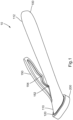
- an antiseptic applicator 10 comprises a substantially hollow body 100, which may be cylindrical in shape, an application member 200 mounted to a distal end portion 110 of the body 100, and a solution container 300 received within the body 100.
- the solution container 300 may be cylindrical or tubular in shape to position the container concentrically into the body 100.
- the body may be any variety of shapes and the container can be any variety of shape that corresponds to (e.g., is congruent to) the particular shape of the body.
- the applicator body may be formed of a single piece or it may be made of multiple pieces combined together.
- the application member 200 may be formed from a foam sponge material, for example, or any suitable material that allows the controlled application of the contained solution from the solution container 300 to a surface external to the applicator 10.
- the material chosen may be porous with a particular soak rate, for example, or may be provided with structural features, including slits or apertures, to direct and control the flow rate of the solution through the application member 200.
- the body 100 may be configured to have a mounting flange 120 at the distal end portion.
- the mounting flange provides a surface for affixing the application member 200 to the body 100.
- the foam may be attached in any acceptable manner known in the relevant art, such as providing a novonette backing to the application member, which allows the application member to be ultrasonically welded to the body of the applicator.
- the solution container 300 is preferably a self-contained structure, formed of a suitable material that is fracturable upon application of sufficient force, e.g., an ampoule.
- a suitable material that is fracturable upon application of sufficient force, e.g., an ampoule.
- the terms “container” and “ampoule” are used interchangeably herein.
- the container is formed of glass, although other materials are within the scope of the present invention.
- the wall of the container is of a thickness sufficient to contain the desired liquid during transport and storage, yet allow the container to be fractured upon the application of localized pressure.
- the container 300 may contain medicaments, chemical compositions, cleansing agents, cosmetics, or the like.
- the container 300 may be filled with antiseptic compositions (e.g., compositions comprising one or more antiseptic molecules) preferably an antimicrobial liquid or gel composition, such as a chlorhexidine gluconate solution or a povidone iodine (PVP-I) alcohol gel solution, for antiseptic application to a patient prior to surgery.
- antiseptic compositions e.g., compositions comprising one or more antiseptic molecules
- an antimicrobial liquid or gel composition such as a chlorhexidine gluconate solution or a povidone iodine (PVP-I) alcohol gel solution
- the antiseptic solution may comprise an alcoholic solvent.
- the alcoholic solvent may be selected from the group consisting of ethanol, isopropanol, and n-propanol.
- the amount of solvent may be from about 40% v/v to about 90% v/v, more preferably about 50% v/v to about 80% v/v, and still more preferably about 60% v/v to about 70% v/v.
- the container may contain antiseptic solution of a sufficient amount to be applied to a desired surface and have an antimicrobial effect on the desired surface.
- the desired surface is a patient's skin.
- the amount of antiseptic solution needed to have an antimicrobial effect on a desired surface to which the antiseptic is applied may vary.
- the amount of antiseptic solution needed is 0.01-100 ml of antiseptic. More preferably, the amount of antiseptic solution need is about 0.5-60 ml and still preferably about 0.5-30 ml. Examples include 0.67, 1.0, 1.5, 3.0, 10.5, and 26.0 ml of antiseptic. However, it will be appreciated that any amount that has an antimicrobial effect on a desired surface may be utilized with the liquid applicator and method.
- Suitable antiseptic molecules include bis-(dihydropyridinyl)-decane derivatives, octenidine salts, cationic surfactants, biguanides, and generally cationic antiseptic molecules.
- Preferred antiseptic agents include octenidine dihydrochloride and chlorhexidine gluconate.
- concentration of the cationic antiseptic in hydroalcoholic solution may vary depending on the specific cationic antiseptic species used or the desired antimicrobial effect that is desired.
- the concentration when using octenidine dihydrochloride or an octenidine salt the concentration may vary from about 0.0001% w/v to about 2.0% w/v, more preferably from about 0.01% w/v to about 0.5% w/v, and still more preferably from about 0.1% w/v to about 0.4% w/v.
- chlorhexidine or a chlorhexidine salt when chlorhexidine or a chlorhexidine salt is used, the concentration may be from about 0.1% w/v to about 2.5% w/v, more preferably from about 0.5% w/v to about 2.25% w/v, and still more preferably about 1.2% w/v to about 2.0% w/v.
- Body 100 also includes an actuator 150.
- Actuator 150 may be any mechanism configured such that, when actuated, fractures the container 300 and also opens a valve, as described in detail below.
- the actuator 150 may be a lever. As shown in FIGS. 1 and 2 the actuator 150 may project from the top portion of body 100. However, it will be appreciated that actuator 150 may project from any portion of body 100.
- the actuator 150 includes a first contact point 152 and a second contact point 154, which apply compressive force to the body 100 when the actuator 150 is actuated.
- the actuator 150 may extend at an angle 156 toward the proximal end 112 of the body 100 (e.g., the free end of the actuator may be located closer to the proximal end of the body than the portion of the actuator connected to the body) such that when the lever is actuated (i.e., pressed toward the body 100), the first contact point 152 applies compressive pressure to the body 100 followed by the second contact point 154 applying compressive pressure to the body 100.
- the actuator and the first and second contact points may be configured (e.g., positioned and angled) such that, upon actuation of the actuator, the first and second contact points contact the body contemporaneously or simultaneously.
- the angle 156 may be from about 1° to about 60°, more preferably from about 5° to about 40°, more preferably from about 10° to about 30°, and still more preferably about 12° to about 18°.
- the actuation of the actuator 150 is described in more detail below.
- a fluid chamber 160 may be formed that extends between the application member 200 and the container 300.
- a fluid metering device such as a pledget 170, for example, may be provided in the fluid chamber 160 to further control and/or direct the flow of solution from the container 300 when the assembly 10 is in use.
- the pledget 170 may tint the solution as the solution flows from the container 300 to the application member 200.
- the pledget 170 may provide enhanced flow control and tinting of the solution as it flows from the container 300 into the pledget 170.
- the pledget may comprise a polyolefin fiber matrix, such as Filtrona Porous Technologies part #X6027.
- the fiber matrix may comprise a homogeneous mixture of bicomponent and monocomponent fibers wherein the monocomponent fibers are formed of the core-forming polymer of the bicomponent fibers, as described in detail in U.S. Patent Nos. 6,103,181 ; 6,576,034 ; 6,616,723 ; 5,633,082 ; 5,620,641 ; 5,607,766 ; and 5,509,430 .
- Altering the material composition will alter material properties such as fluid adsorption and flow rate. Additionally, altering the fiber density will also alter the properties such as flow, porosity, and adsorption.
- An example fiber density may be about 0.5 g/cc. Higher fiber density increases residence time for the antiseptic solution which increases the intensity of color.
- any suitable hydrophobic polymer material that allows for the flow of a hydroalcoholic solvent may be used.
- the polymer may be a non-woven polyester.
- the pledget 170 may have a dye incorporated therein so that the antiseptic solution becomes tinted as it passes through the pledget.
- the impregnated dye is anionic in nature.
- the anionic dye may be any suitable dye approved by the FDA and international authorities for use in food, drugs, and/or cosmetics (e.g., D&C and FD&C dyes).
- Preferred dyes may be selected from the group consisting of FD&C Blue No. 1 (Brilliant Blue FCF), FD&C Blue No. 2 (Indigo Carmine), FD&C Green No. 3 (Fast Green FCF), FD&C Red No. 3 (Erythrosine), FD&C Red No. 40 (Allura Red), FD&C Yellow No.
- FD&C Yellow No. 6 (Sunset Yellow FCF), D&C Yellow No. 8 (Fluorescein), D&C Orange No. 4, D&C Yellow 10 (Quinoline Yellow WS), D&C Yellow No. 11, D&C Red No. 30, and combinations thereof.
- suitable dyes include beta-carotene, curcumin, iron oxide yellow, and riboflavin, iron oxide red, chlorophyll, and the like. Two or more anionic dyes may also be combined and used together. For example, by combining D&C Yellow No. 8 and FD&C Red No. 40 mixed in a 80%/20% w/w basis, an orange tint is produced.
- Ratios of yellow to red dye may be from 1%:99% w/w to 99%:1% w/w. Additionally, it has been found that when combinations of dyes are incorporated into the pledget, a color change is observed in the antiseptic solution after it is applied to a surface. In particular, because of solubility differences, a particular dye having less solubility will take longer to solubilize in the antiseptic solution. The more soluble color will be exhibited first, then, over time, the less soluble color will be mixed with the more soluble color and a new color will be exhibited as the solution dries. For example, it has been found that when a blend of more than 50% w/w D&C Yellow No. 8 with FD&C Red No.
- the antiseptic solution initially has a yellow color, which changes gradually to orange over time as the red dye is solubilized and mixed with the yellow dye.
- the applied antiseptic solution will start out yellow, turn orange, and then finally dark orange within a short period of time, such as on the order of less than 10 seconds as the solution dries on the skin.
- the deposited dye and drug molecules remain (together referred herein as "the deposit") on the skin surface. The color exhibited by these molecules will change as the solution continues to dry.
- the solution starts out yellow, and as the solution dries and the concentration of the dyes and drug (i.e., the deposit) increase relative to the solvents, the skin surface will turn light orange and then ultimately appear dark orange once dried.
- the time will vary based on particular fiber density, selected dye(s), and relative amount of particular dyes within the blend of dyes when a blend is used. This color-changing aspect allows the practitioner to visually confirm that the antiseptic solution has dried on the surface.
- Another example blend comprises Yellow 10 and Red 40, which may be used together in the same ratio as provided above with respect to the blend of Yellow 8 and Red 40.
- the applicator 10 may include a valve 250 disposed within fluid chamber 160 and downstream of the pledget 170.
- the valve 250 may include a slit 252 separating the valve into two opposing portions 251, 253. Thus, the valve 250 is bifurcated.
- the valve 250 allows reduction of flow rate without entirely stopping the flow, which is described in more detail below.
- the valve 250 may be positioned within the fluid chamber 160 such the valve 250 contacts the portion of the tube 100 that receives compressing pressure from the first contact point 152 of the lever 150 when the lever 150 is actuated.
- the valve 250 may be disposed sufficiently close to the portion of the tube 100 that receives the compressing pressure from the first contact point 152 so that the valve 250 experiences the compressing force from the first contact point 152.
- the valve 250 may be disposed within about 7 mm, more preferably within about 4 mm, and still more preferably within about 2 mm of the portion of the tube 100 that receives the compressing pressure from the first contact point 152.
- the valve 250 When the valve 250 is positioned in the above-described manner, the compressive force applied to the body 100 via the first contact point is transferred to the valve 250.
- the valve 250 may be configured to open when pressure is applied to the outer circumference of the valve 250.
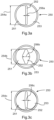
- the valve 250 is shown in detail in FIGS. 3A-3C.
- FIGS. 3A-3C show front views of the valve 250 (i.e., the views show the surface of the valve that faces the application member 200).
- FIG. 3A shows a front view of the valve 250 prior to actuation of the actuator 150, i.e., prior to the application of any compressive force.
- FIG. 3B shows a front view of the valve 250 during maximum actuation of the actuator 150, i.e., during maximum application of compressive force.
- FIG. 3C shows a front view of the valve 250 after actuation of the actuator 150 has been discontinued, i.e., when the compressive force has been removed.
- the slit 252 may extend substantially vertically within the body 100, i.e., perpendicular to a longitudinal axis of the body 100 along the height of the body 100.
- the slit 252 may extend from in a straight line from the 12 o'clock position to the 6 o'clock position.
- the slit 252 may be angled up to ⁇ 15° from the 12 o'clock/6 o'clock position, more preferably up to ⁇ 10°, still more preferably ⁇ 5°, and most preferably ⁇ 1°.
- the slit may have a substantially uniform height 254a and a substantially uniform width 256a.
- the height 254a of the slit 252 in the pre-actuated state may be about or near equal to the height of body 100.
- the ratio of the height 254a of the slit 252 to the height 258 of the body 100 may be from about 0.7:1 to about 1:1, more preferably about 0.75:1 to about 0.95:1, and still more preferably from about 0.8:1 to 0.9:1.
- the height 254a of the slit 252 may be about 8 mm to about 15 mm, more preferably about 7 mm to about 13 mm, and still more preferably about 8 mm to about 10 mm. The height may be optimized based upon the size of the container.
- the ratio of the width 256a of the slit 252 to the height 254a of the slit 252, prior to actuation, may be from about 8:1 to about 14:1, more preferably about 9:1 to about 13:1, and still more preferably about 12:1.
- the width 256a of the slit 252 may be from about 0.25 mm to about 1.5 mm, more preferably about 0.5 mm to about 1.0 mm, and still more preferably about 0.80 mm to about 0.85 mm.
- the valve 250 may comprise a material with sufficient strength and elasticity such that applying a force onto the valve 250 in a direction parallel to the height of the slit 252 (i.e., in a direction perpendicular to the longitudinal axis of the body 100 along the height of the body) will cause the two opposing valve portions 251, 253 to move away from each other, thereby widening the slit 252. That is, the two opposing valve portions 251, 253 move in a direction perpendicular to the height of the slit 252 and perpendicular to the longitudinal axis of the of body 100 (i.e., in a direction along the width of the body 100 toward the inner surface of the body), thereby expanding the slit 252 ( FIG. 3B ).
- the material may also have sufficient strength and elasticity such that once the force is removed the valve portions 251, 253 retract in a direction opposite to the stretching direction, i.e., in a direction along the width of the body toward the center of the body 100 ( FIG. 3C ).
- the valve 252 may have a Shore durometer from about 40A to about 60A.
- the valve may comprise a material having a Shore durometer of about 40A.
- the valve may comprise a material having a Shore durometer of about 60A.
- the material may comprise silicone, for example.
- the width 254b and height 256b of the slit 252 are altered as compared to width 254a and height 256a in the non-activated state.
- the height 254b may be smaller than the height 254a, while the width 256b is many times larger than the width 256a, in particular at a midway point along the height 254b.
- the ratio of the height 254a to the height 254b may be from about 1:0.7 to about 1:0.9, preferably about 1:0.75 to about 1:0.85, more preferably about 1:0.8.
- the ratio of the width 256a to the width 256b (at the midpoint of the height 254b) may be from about 1:2 to about 1:10, preferably about 1:4 to about 1:8, and still more preferably about 1:6.
- the slit 252 width is greatest at the midpoint of the height 256a and gradually decreases/tapers toward the top and bottom of the slit 252.
- the height 254b may be from about 6 mm to 9 mm, more preferably about 6.5 mm to about 8.5 mm, still more preferably 7.0 mm to about 8.0 mm, and most preferably about 7.75 mm.
- the width 256b may be from about 1.5 mm to about 4 mm, more preferably about 2.0 mm to about 3.5 mm, and still more preferably about 3.5 mm.
- the height 254c and the width 256c of the slit 252 return to sizes close to the sizes of the height 254a and width 256a of the slit 252 prior to actuation.
- the height 254c will remain slightly smaller than the height 254a and the width 256c will remain slightly larger than the width 256a.
- the ratio of the height 254a to the height 254c may be from about 1:85 to about 1:0.95, more preferably about 1:0.9.
- the ratio of the width 256a to the width 256c may be from about 1:1.25 to about 1:3, more preferably about 1:1.5 to about 1:2.50, and still more preferably about 1:2. Because the width 256c remains even after the actuation is removed, there will still be fluid flow after the actuator is released. Thus, the valve 252 allows for increased and reduced fluid flow rate, but does stop the flow of fluid.
- Activation of the applicator to release the solution and control the flow may be achieved by one handed actuation of the actuator 150.
- the operator first grasps the tube 100 and the actuator 150. Prior to applying compressive force on the actuator 150, the valve 250 is in the pre-actuated configuration shown in FIG. 3A .
- the operator desires to release the fluid contained in the container 300, the operator begins to compress the actuator 150 toward the body 100 by applying a compressive force onto the actuator 150.
- the first contact point 152 begins to apply pressure on the body 100. This pressure then applies pressure on the valve 250 that is located directly adjacent to or sufficiently near the first contact point 152.
- valve 250 will be in the actuated state shown in FIG. 3B .
- the operator can control the flow of fluid through the valve 250 by removing the compressive force from the actuator 150.
- the pressure at the first contact point 152 will decrease and the elastic property of the valve 250 will cause the slit width to decrease and the height to increase.
- the slit 252 will have the configuration shown in FIG. 3C , thereby greatly reducing the flow rate as compared to that configured of FIG. 3B .
- the operator may alternate between actuating and releasing the actuator 150 to switch between maximum flow rate ( FIG. 3B ) and minimum flow rate ( FIG. 3C ).
- the applicator 10 allows the operator to easily control the initial and continued release of fluid and the flow rate of fluid with one hand.
- the width 256c remains after releasing the actuator, there will still be a minimum flow rate when the actuator is released.
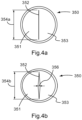
- FIGS. 4A and 4B show a valve 350.
- the valve 350 differs from the valve 250 in that the valve 350 provides an on/off configuration.
- actuation of the actuator will allow for fluid flow, but when the actuator is released, the valve 350 will substantially close, thereby substantially stopping the flow of fluid (as opposed to merely reducing the fluid flow rate).
- the valve 350 may be used in the applicator 10 in the same manner and in the same position/orientation as shown in FIG. 2 , and as discussed above with respect to the valve 250.
- the valve 350 may include a slit 352 separating the valve into two opposing portions 351, 353. Thus, the valve 350 is bifurcated.
- the valve 350 may be similarly configured to open when pressure is applied to the outer circumference of the valve 350.
- FIGS. 4A and 4B show the same views as shown in FIGS. 3A and 3B , respectively. That is, FIGS 4A and 4B show front views of the valve 350 (i.e., the views show the surface of the valve that faces the application member 200).
- FIG. 4A shows a front view of the valve 350 prior to actuation of the actuator 150, i.e., prior to the application of any compressive force.
- FIG. 4B shows a front view of the valve 350 during maximum actuation of the actuator 150, i.e., during maximum application of compressive force.
- the orientation of the slit 350 and the height 354a of the slit 352 in the pre-actuated state is the same as in the slit 250 shown in FIG. 3A .
- the width of the slit 352, however, is different. As shown in FIG. 4A , in the pre-actuated state, the opposing portions 351, 353, may be substantially flush against each other. Thus, the width of the slit may be substantially 0 (zero).
- the valve 350 may comprise a material with sufficient strength and elasticity such that applying a force onto the valve 350 in a direction parallel to the height of the slit 352 (i.e., in a direction perpendicular to the longitudinal axis of the body 100 along the height of the body) will cause the two opposing valve portions 351, 353 to move away from each other, thereby widening the slit 352. That is, the two opposing valve portions 351, 353 move in a direction perpendicular to the height of the slit 352 and perpendicular to the longitudinal axis of the of body 100 (i.e., in a direction along the width of the body 100 toward the inner surface of the body), thereby expanding the slit 352 ( FIG. 4B ).
- the material may also have sufficient strength and elasticity such that once the force is removed the valve portions 351, 353 retract in a direction opposite to the stretching direction, i.e., in a direction along the width of the body toward the center of the body 100.
- the valve 352 may have a Shore durometer from about 40A to about 60A.
- the valve may comprise a material having a Shore durometer of about 40A.
- the valve may comprise a material having a Shore durometer of about 60A.
- the material may comprise silicone, for example.
- the width 356 and height 354b of the slit 352 are altered as compared to width and height 354a in the non-activated state.
- the height 354b may be smaller than the height 354a, and while there is no slit width prior to actuation, there is a slit width 354b during actuation.
- the ratio of the height 354a to the height 354b may be from about 1:0.7 to about 1:0.9, preferably about 1:0.75 to about 1:0.85, more preferably about 1:0.8.
- a ratio of the width 356 to a ratio of the height 354b may be about 1:10 to about 1:15, more preferably about 1:11 to about 1:14, still more preferably 1:12 to about 1:13.
- the height 354b may be about 7 mm to about 10 mm, more preferably about 7.5 mm to about 9.5 mm, still more preferably 8.0 mm to about 9.0 mm, and most preferably about 9.0 mm.
- the width 356 may be from about 0.50 mm to about 1.0 mm, more preferably about 0.7 mm to about 0.9 mm, and still more preferably about 0.8 mm.
- the height and the width of the slit 352 return to sizes very close to the sizes of the height and width of the slit 352 prior to actuation.
- the ratio of the height 354a to the height after compressive force is removed is substantially 1:1.
- the width of the slit 352 after compressive force is removed is essentially 0 (zero). That is, when the compressive force is removed, the two valve portions 351, 353 may be substantially flush against each other.
- the released state of the slit 352 appears substantially the same as shown in FIG. 4A .
- the valve 350 provides different flow control as compared to the valve 250 because of the smaller initial slit width and because the valve closes when compressive force is removed. Operation of the actuator to actuate the valve and release solution from the container is the same as discussed above.
- the valve 350 thus provides an "on/off' control because the slit 352 returns to an approximately flush state (i.e., the width of the slit 352 is about or near 0 (zero)) after the compressive force is removed.
- the operator can allow fluid flow (i.e., "on”) by actuating the actuator and reduce the fluid flow to about or near zero (i.e., "off”) by removing actuation of the actuator.
- the solution may then soak into, or otherwise flow through, the application material 200 at an operator controlled rate.
- the fluid chamber 160 may serve to accumulate and distribute the solution evenly over substantially the entire area of the application material 200. Once the application material 200 is engorged, for example, the solution may then be applied to a patient by wiping the distal surface of the application material 200 against the skin.
- the applicator may include any non-mutually exclusive features described in a variety of known applicators.
- the applicator could include a dual ampoule arrangement such as described in U.S. Patent No. 7,182,536 .
- Other relevant features can be found in U.S. Patent Application Publication Nos.
Landscapes
- Health & Medical Sciences (AREA)
- Animal Behavior & Ethology (AREA)
- Veterinary Medicine (AREA)
- Public Health (AREA)
- General Health & Medical Sciences (AREA)
- Life Sciences & Earth Sciences (AREA)
- Biomedical Technology (AREA)
- Engineering & Computer Science (AREA)
- Anesthesiology (AREA)
- Heart & Thoracic Surgery (AREA)
- Hematology (AREA)
- Epidemiology (AREA)
- General Chemical & Material Sciences (AREA)
- Chemical Kinetics & Catalysis (AREA)
- Chemical & Material Sciences (AREA)
- Media Introduction/Drainage Providing Device (AREA)
- Coating Apparatus (AREA)
- Magnetic Heads (AREA)
Description
- The present disclosure relates to an antiseptic applicator and method of use thereof, and more particularly, to an antiseptic applicator that uses a compressive force to actuate release of a sealed solution, preferably an antimicrobial solution, from a container.
- Antiseptic applicators for the preparation of a patient prior to surgery, for example, are known and common in the prior art. Conventional applicators rely on various means of actuation to release a self-contained reservoir of antimicrobial solution for sterilization of the patient's skin. For example, a number of applicators are designed with a puncturing means. These applicators typically include a head with a spike, for example, and a sealed container or cartridge. A push or screw motion is employed to axially translate the head toward the sealed container so that the spike may pierce the sealed container and effectuate the release of the solution contained therein. Some examples of applicators using a puncturing means include
U.S. Pat. Nos. 4,415,288 ;4,498,796 ;5,769,552 ;6,488,665 ; and7,201,525 ; andU.S. Pat. Pub. No. 2006/0039742 . - Other conventional applicators rely on fracturing an internally situated frangible container or ampoule through the application of a one-way directional force or a localized application of pressure. The directional force is typically applied longitudinally to one end of the ampoule by a pushing motion designed to force the ampoule to fracture under a compressive stress, sometimes at a predetermined area of stress concentration. Alternatively, a pressure may be applied to a localized section of the ampoule through a squeezing motion designed to crush a section of the frangible ampoule in order to release the antimicrobial solution contained therein. Some examples of applicators using frangible ampoules in the manner discussed above include
U.S. Pat. Nos. 3,757,782 ;5,288,159 ;5,308,180 ;5,435,660 ;5,445,462 ;5,658,084 ;5,772,346 ;5,791,801 ;5,927,884 ;6,371,675 ; and6,916,133 . - However, in the above-listed applicators, once the fluid is released from the container, there is no mechanism to control the flow of antiseptic solution to the surface (e.g., skin of a patient). Thus, there is a need in the art for an antiseptic applicator that allows for convenient and ergonomic control of the flow of antiseptic solution after the antiseptic fluid has been released from the container or ampoule.
- The invention consists of an applicator assembly as described in claim 1 and a method for applying a solution to a surface as described in claim 7.
- It will become readily apparent to those skilled in the art from the following detailed description, wherein it is shown and described only exemplary configurations of an applicator assembly. As will be realized, the invention includes other and different aspects of an applicator and assembly and the various details presented throughout this disclosure are capable of modification in various other respects, all without departing from the scope of the invention. Accordingly, the drawings and the detailed description are to be regarded as illustrative in nature and not as restrictive.
-
-
FIG. 1 is a perspective view of an antiseptic applicator, in accordance with certain aspects of the present invention; -
FIG. 2 is a cross sectional view of the antiseptic applicator ofFIG. 1 ; -
FIG. 3A is a front view of a valve in an pre-actuated configuration, in accordance with certain aspects of the present invention; -
FIG. 3B is a front view of the valve ofFIG. 3A in an actuated configuration; -
FIG. 3C is a front view of the valve ofFIG. 3A in a released configuration; -
FIG. 4A is a front view of a valve in a pre-actuated configuration in accordance with other aspects of the present invention; and -
FIG. 4B is a front view of the valve ofFIG. 4A in an actuated configuration. - Various aspects of an antiseptic applicator may be illustrated by describing components that are coupled, attached, and/or joined together. As used herein, the terms "coupled", "attached", and/or "joined" are used to indicate either a direct connection between two components or, where appropriate, an indirect connection to one another through intervening or intermediate components. In contrast, when a component is referred to as being "directly coupled", "directly attached", and/or "directly joined" to another component, there are no intervening elements present.
- Relative terms such as "lower" or "bottom" and "upper" or "top" may be used herein to describe one element's relationship to another element illustrated in the drawings. It will be understood that relative terms are intended to encompass different orientations of an antiseptic applicator in addition to the orientation depicted in the drawings. By way of example, if an antiseptic applicator in the drawings is turned over, elements described as being on the "bottom" side of the other elements would then be oriented on the "top" side of the other elements. The term "bottom" can therefore encompass both an orientation of "bottom" and "top" depending on the particular orientation of the apparatus.
- Various aspects of an antiseptic applicator may be illustrated with reference to one or more exemplary embodiments. As used herein, the term "exemplary" means "serving as an example, instance, or illustration," and should not necessarily be construed as preferred or advantageous over other embodiments of an antiseptic applicator disclosed herein.
- The term "about" as used herein means ±10%, more preferably ±5%, and still more preferably ±1% of the provided value.
- As shown in
FIGS. 1 and2 , anantiseptic applicator 10 comprises a substantiallyhollow body 100, which may be cylindrical in shape, anapplication member 200 mounted to adistal end portion 110 of thebody 100, and asolution container 300 received within thebody 100. Thesolution container 300 may be cylindrical or tubular in shape to position the container concentrically into thebody 100. In other aspects of the present invention, the body may be any variety of shapes and the container can be any variety of shape that corresponds to (e.g., is congruent to) the particular shape of the body. In an aspect of the present invention the applicator body may be formed of a single piece or it may be made of multiple pieces combined together. - The
application member 200 may be formed from a foam sponge material, for example, or any suitable material that allows the controlled application of the contained solution from thesolution container 300 to a surface external to theapplicator 10. The material chosen may be porous with a particular soak rate, for example, or may be provided with structural features, including slits or apertures, to direct and control the flow rate of the solution through theapplication member 200. Thebody 100 may be configured to have amounting flange 120 at the distal end portion. The mounting flange provides a surface for affixing theapplication member 200 to thebody 100. In an aspect, the foam may be attached in any acceptable manner known in the relevant art, such as providing a novonette backing to the application member, which allows the application member to be ultrasonically welded to the body of the applicator. - The
solution container 300 is preferably a self-contained structure, formed of a suitable material that is fracturable upon application of sufficient force, e.g., an ampoule. The terms "container" and "ampoule" are used interchangeably herein. Preferably, the container is formed of glass, although other materials are within the scope of the present invention. The wall of the container is of a thickness sufficient to contain the desired liquid during transport and storage, yet allow the container to be fractured upon the application of localized pressure. Thecontainer 300 may contain medicaments, chemical compositions, cleansing agents, cosmetics, or the like. For example, thecontainer 300 may be filled with antiseptic compositions (e.g., compositions comprising one or more antiseptic molecules) preferably an antimicrobial liquid or gel composition, such as a chlorhexidine gluconate solution or a povidone iodine (PVP-I) alcohol gel solution, for antiseptic application to a patient prior to surgery. Thecontainer 300 is designed to withstand various heat and chemical sterilization techniques, which may be performed sequentially with a solution filling process, in accordance with techniques that are well known in the art. - The antiseptic solution may comprise an alcoholic solvent. For example, the alcoholic solvent may be selected from the group consisting of ethanol, isopropanol, and n-propanol. The amount of solvent may be from about 40% v/v to about 90% v/v, more preferably about 50% v/v to about 80% v/v, and still more preferably about 60% v/v to about 70% v/v.
- The container may contain antiseptic solution of a sufficient amount to be applied to a desired surface and have an antimicrobial effect on the desired surface. In one aspect, the desired surface is a patient's skin. It will be appreciated that the amount of antiseptic solution needed to have an antimicrobial effect on a desired surface to which the antiseptic is applied may vary. In one aspect the amount of antiseptic solution needed is 0.01-100 ml of antiseptic. More preferably, the amount of antiseptic solution need is about 0.5-60 ml and still preferably about 0.5-30 ml. Examples include 0.67, 1.0, 1.5, 3.0, 10.5, and 26.0 ml of antiseptic. However, it will be appreciated that any amount that has an antimicrobial effect on a desired surface may be utilized with the liquid applicator and method.
- Suitable antiseptic molecules include bis-(dihydropyridinyl)-decane derivatives, octenidine salts, cationic surfactants, biguanides, and generally cationic antiseptic molecules. Preferred antiseptic agents include octenidine dihydrochloride and chlorhexidine gluconate. The concentration of the cationic antiseptic in hydroalcoholic solution may vary depending on the specific cationic antiseptic species used or the desired antimicrobial effect that is desired. For example, when using octenidine dihydrochloride or an octenidine salt the concentration may vary from about 0.0001% w/v to about 2.0% w/v, more preferably from about 0.01% w/v to about 0.5% w/v, and still more preferably from about 0.1% w/v to about 0.4% w/v. When chlorhexidine or a chlorhexidine salt is used, the concentration may be from about 0.1% w/v to about 2.5% w/v, more preferably from about 0.5% w/v to about 2.25% w/v, and still more preferably about 1.2% w/v to about 2.0% w/v.
-
Body 100 also includes anactuator 150.Actuator 150 may be any mechanism configured such that, when actuated, fractures thecontainer 300 and also opens a valve, as described in detail below. In an aspect of the present invention theactuator 150 may be a lever. As shown inFIGS. 1 and2 theactuator 150 may project from the top portion ofbody 100. However, it will be appreciated thatactuator 150 may project from any portion ofbody 100. Theactuator 150 includes afirst contact point 152 and asecond contact point 154, which apply compressive force to thebody 100 when theactuator 150 is actuated. Theactuator 150 may extend at anangle 156 toward theproximal end 112 of the body 100 (e.g., the free end of the actuator may be located closer to the proximal end of the body than the portion of the actuator connected to the body) such that when the lever is actuated (i.e., pressed toward the body 100), thefirst contact point 152 applies compressive pressure to thebody 100 followed by thesecond contact point 154 applying compressive pressure to thebody 100. In another aspect of the present invention, the actuator and the first and second contact points may be configured (e.g., positioned and angled) such that, upon actuation of the actuator, the first and second contact points contact the body contemporaneously or simultaneously. Theangle 156 may be from about 1° to about 60°, more preferably from about 5° to about 40°, more preferably from about 10° to about 30°, and still more preferably about 12° to about 18°. The actuation of theactuator 150 is described in more detail below. - With the
container 300 concentrically mounted in thebody 100, as described above, and theapplication member 200 mounted to close off thedistal end portion 110 of thebody 100, afluid chamber 160 may be formed that extends between theapplication member 200 and thecontainer 300. A fluid metering device, such as apledget 170, for example, may be provided in thefluid chamber 160 to further control and/or direct the flow of solution from thecontainer 300 when theassembly 10 is in use. In accordance with another aspect of the present invention, thepledget 170 may tint the solution as the solution flows from thecontainer 300 to theapplication member 200. - In an aspect of the present invention, the
pledget 170 may provide enhanced flow control and tinting of the solution as it flows from thecontainer 300 into thepledget 170. The pledget may comprise a polyolefin fiber matrix, such as Filtrona Porous Technologies part #X6027. The fiber matrix may comprise a homogeneous mixture of bicomponent and monocomponent fibers wherein the monocomponent fibers are formed of the core-forming polymer of the bicomponent fibers, as described in detail inU.S. Patent Nos. 6,103,181 ;6,576,034 ;6,616,723 ;5,633,082 ;5,620,641 ;5,607,766 ; and5,509,430 . Altering the material composition will alter material properties such as fluid adsorption and flow rate. Additionally, altering the fiber density will also alter the properties such as flow, porosity, and adsorption. An example fiber density may be about 0.5 g/cc. Higher fiber density increases residence time for the antiseptic solution which increases the intensity of color. In an aspect of the present invention, any suitable hydrophobic polymer material that allows for the flow of a hydroalcoholic solvent may be used. For example, the polymer may be a non-woven polyester. - The
pledget 170 may have a dye incorporated therein so that the antiseptic solution becomes tinted as it passes through the pledget. Preferably, the impregnated dye is anionic in nature. The anionic dye may be any suitable dye approved by the FDA and international authorities for use in food, drugs, and/or cosmetics (e.g., D&C and FD&C dyes). Preferred dyes may be selected from the group consisting of FD&C Blue No. 1 (Brilliant Blue FCF), FD&C Blue No. 2 (Indigo Carmine), FD&C Green No. 3 (Fast Green FCF), FD&C Red No. 3 (Erythrosine), FD&C Red No. 40 (Allura Red), FD&C Yellow No. 5 (Tartrazine), FD&C Yellow No. 6 (Sunset Yellow FCF), D&C Yellow No. 8 (Fluorescein), D&C Orange No. 4, D&C Yellow 10 (Quinoline Yellow WS), D&C Yellow No. 11, D&C Red No. 30, and combinations thereof. Other suitable dyes include beta-carotene, curcumin, iron oxide yellow, and riboflavin, iron oxide red, chlorophyll, and the like. Two or more anionic dyes may also be combined and used together. For example, by combining D&C Yellow No. 8 and FD&C Red No. 40 mixed in a 80%/20% w/w basis, an orange tint is produced. Ratios of yellow to red dye may be from 1%:99% w/w to 99%:1% w/w. Additionally, it has been found that when combinations of dyes are incorporated into the pledget, a color change is observed in the antiseptic solution after it is applied to a surface. In particular, because of solubility differences, a particular dye having less solubility will take longer to solubilize in the antiseptic solution. The more soluble color will be exhibited first, then, over time, the less soluble color will be mixed with the more soluble color and a new color will be exhibited as the solution dries. For example, it has been found that when a blend of more than 50% w/w D&C Yellow No. 8 with FD&C Red No. 40 is used, the antiseptic solution initially has a yellow color, which changes gradually to orange over time as the red dye is solubilized and mixed with the yellow dye. During a typical application of the above yellow/red blend, the applied antiseptic solution will start out yellow, turn orange, and then finally dark orange within a short period of time, such as on the order of less than 10 seconds as the solution dries on the skin. In particular, as the solution dries, the deposited dye and drug molecules remain (together referred herein as "the deposit") on the skin surface. The color exhibited by these molecules will change as the solution continues to dry. Thus, in the yellow/red blend, the solution starts out yellow, and as the solution dries and the concentration of the dyes and drug (i.e., the deposit) increase relative to the solvents, the skin surface will turn light orange and then ultimately appear dark orange once dried. The time will vary based on particular fiber density, selected dye(s), and relative amount of particular dyes within the blend of dyes when a blend is used. This color-changing aspect allows the practitioner to visually confirm that the antiseptic solution has dried on the surface. Another example blend comprises Yellow 10 and Red 40, which may be used together in the same ratio as provided above with respect to the blend of Yellow 8 and Red 40. - The
applicator 10 may include avalve 250 disposed withinfluid chamber 160 and downstream of thepledget 170. Thevalve 250 may include aslit 252 separating the valve into two opposingportions valve 250 is bifurcated. Thevalve 250 allows reduction of flow rate without entirely stopping the flow, which is described in more detail below. Thevalve 250 may be positioned within thefluid chamber 160 such thevalve 250 contacts the portion of thetube 100 that receives compressing pressure from thefirst contact point 152 of thelever 150 when thelever 150 is actuated. In another aspect of the present invention, thevalve 250 may be disposed sufficiently close to the portion of thetube 100 that receives the compressing pressure from thefirst contact point 152 so that thevalve 250 experiences the compressing force from thefirst contact point 152. For example, thevalve 250 may be disposed within about 7 mm, more preferably within about 4 mm, and still more preferably within about 2 mm of the portion of thetube 100 that receives the compressing pressure from thefirst contact point 152. When thevalve 250 is positioned in the above-described manner, the compressive force applied to thebody 100 via the first contact point is transferred to thevalve 250. - The
valve 250 may be configured to open when pressure is applied to the outer circumference of thevalve 250. Thevalve 250 is shown in detail inFIGS. 3A-3C. FIGS. 3A-3C show front views of the valve 250 (i.e., the views show the surface of the valve that faces the application member 200).FIG. 3A shows a front view of thevalve 250 prior to actuation of theactuator 150, i.e., prior to the application of any compressive force.FIG. 3B shows a front view of thevalve 250 during maximum actuation of theactuator 150, i.e., during maximum application of compressive force.FIG. 3C shows a front view of thevalve 250 after actuation of theactuator 150 has been discontinued, i.e., when the compressive force has been removed. - As shown in
FIGS. 3A-3C theslit 252 may extend substantially vertically within thebody 100, i.e., perpendicular to a longitudinal axis of thebody 100 along the height of thebody 100. In other words, when looking at a face of thevalve 250 when the applicator is oriented such that the actuator extends from the top of the applicator (i.e. the orientation shown inFIG. 2 ), theslit 252 may extend from in a straight line from the 12 o'clock position to the 6 o'clock position. Theslit 252 may be angled up to ± 15° from the 12 o'clock/6 o'clock position, more preferably up to ± 10°, still more preferably ± 5°, and most preferably ± 1°. In the pre-actuated configuration shown inFIG. 3A , the slit may have a substantiallyuniform height 254a and a substantiallyuniform width 256a. Theheight 254a of theslit 252 in the pre-actuated state may be about or near equal to the height ofbody 100. For example, the ratio of theheight 254a of theslit 252 to theheight 258 of thebody 100 may be from about 0.7:1 to about 1:1, more preferably about 0.75:1 to about 0.95:1, and still more preferably from about 0.8:1 to 0.9:1. In an aspect of the present invention, theheight 254a of theslit 252 may be about 8 mm to about 15 mm, more preferably about 7 mm to about 13 mm, and still more preferably about 8 mm to about 10 mm. The height may be optimized based upon the size of the container. The ratio of thewidth 256a of theslit 252 to theheight 254a of theslit 252, prior to actuation, may be from about 8:1 to about 14:1, more preferably about 9:1 to about 13:1, and still more preferably about 12:1. For example thewidth 256a of theslit 252 may be from about 0.25 mm to about 1.5 mm, more preferably about 0.5 mm to about 1.0 mm, and still more preferably about 0.80 mm to about 0.85 mm. - The
valve 250 may comprise a material with sufficient strength and elasticity such that applying a force onto thevalve 250 in a direction parallel to the height of the slit 252 (i.e., in a direction perpendicular to the longitudinal axis of thebody 100 along the height of the body) will cause the two opposingvalve portions slit 252. That is, the two opposingvalve portions slit 252 and perpendicular to the longitudinal axis of the of body 100 (i.e., in a direction along the width of thebody 100 toward the inner surface of the body), thereby expanding the slit 252 (FIG. 3B ). The material may also have sufficient strength and elasticity such that once the force is removed thevalve portions FIG. 3C ). For example, thevalve 252 may have a Shore durometer from about 40A to about 60A. In an aspect, the valve may comprise a material having a Shore durometer of about 40A. In another aspect, the valve may comprise a material having a Shore durometer of about 60A. The material may comprise silicone, for example. - As shown in
FIG. 3B , in the actuated state, i.e., when compressive force has been applied to thevalve 250, thewidth 254b andheight 256b of theslit 252 are altered as compared towidth 254a andheight 256a in the non-activated state. Specifically, theheight 254b may be smaller than theheight 254a, while thewidth 256b is many times larger than thewidth 256a, in particular at a midway point along theheight 254b. For example the ratio of theheight 254a to theheight 254b may be from about 1:0.7 to about 1:0.9, preferably about 1:0.75 to about 1:0.85, more preferably about 1:0.8. The ratio of thewidth 256a to thewidth 256b (at the midpoint of theheight 254b) may be from about 1:2 to about 1:10, preferably about 1:4 to about 1:8, and still more preferably about 1:6. As shown inFIG. 3B , in the actuated state, theslit 252 width is greatest at the midpoint of theheight 256a and gradually decreases/tapers toward the top and bottom of theslit 252. In an example aspect, theheight 254b may be from about 6 mm to 9 mm, more preferably about 6.5 mm to about 8.5 mm, still more preferably 7.0 mm to about 8.0 mm, and most preferably about 7.75 mm. In an example aspect, thewidth 256b may be from about 1.5 mm to about 4 mm, more preferably about 2.0 mm to about 3.5 mm, and still more preferably about 3.5 mm. - As shown in
FIG. 3C in the released state, i.e., when the compressive force has been removed from thevalve 250, theheight 254c and thewidth 256c of theslit 252 return to sizes close to the sizes of theheight 254a andwidth 256a of theslit 252 prior to actuation. However, as shownFIG. 3C , due to the initial dimensions of the slit 252 (as shown inFIG. 3A ) and the elastic and hardness properties of the materials, theheight 254c will remain slightly smaller than theheight 254a and thewidth 256c will remain slightly larger than thewidth 256a. For example the ratio of theheight 254a to theheight 254c may be from about 1:85 to about 1:0.95, more preferably about 1:0.9. The ratio of thewidth 256a to thewidth 256c may be from about 1:1.25 to about 1:3, more preferably about 1:1.5 to about 1:2.50, and still more preferably about 1:2. Because thewidth 256c remains even after the actuation is removed, there will still be fluid flow after the actuator is released. Thus, thevalve 252 allows for increased and reduced fluid flow rate, but does stop the flow of fluid. - Activation of the applicator to release the solution and control the flow may be achieved by one handed actuation of the
actuator 150. To operate the applicator, the operator first grasps thetube 100 and theactuator 150. Prior to applying compressive force on theactuator 150, thevalve 250 is in the pre-actuated configuration shown inFIG. 3A . When the operator desires to release the fluid contained in thecontainer 300, the operator begins to compress theactuator 150 toward thebody 100 by applying a compressive force onto theactuator 150. As theactuator 150 begins to move toward thebody 100, thefirst contact point 152 begins to apply pressure on thebody 100. This pressure then applies pressure on thevalve 250 that is located directly adjacent to or sufficiently near thefirst contact point 152. As the operator continues to press theactuator 150 the pressure continues to increase on thevalve 250, thereby increasing the width and decreasing the height of theslit 252. Upon further actuation of theactuator 150 thesecond contact point 154 begins to contact thebody 100. By this point, thevalve 250 will be in the actuated state shown inFIG. 3B . - The operator then continues to compress the
actuator 150 imparting pressure on thebody 100 via thesecond contact point 154. Once sufficient compressive force is imparted at thesecond contact point 154,container 300 fractures, thereby releasing flow of the fluid contained therein. The solution will drain from thecontainer 300 into thefluid chamber 160 under its own weight. After passing through thepledget 170 and becoming tinted, the fluid flow passes through theopen slit 252. If the operator continues to apply pressure on theactuator 150, the continued pressure at thefirst contact point 152 will cause the valve slit 252 to remain fully actuated as shown inFIG. 3B , thereby providing maximum flow rate. However, because thevalve 250 biases toward the position shown inFIG. 3C , the operator can control the flow of fluid through thevalve 250 by removing the compressive force from theactuator 150. As the operator removes the compressive force from theactuator 150, the pressure at thefirst contact point 152 will decrease and the elastic property of thevalve 250 will cause the slit width to decrease and the height to increase. When the operator totally releases the compressive force on thelever 150, theslit 252 will have the configuration shown inFIG. 3C , thereby greatly reducing the flow rate as compared to that configured ofFIG. 3B . The operator may alternate between actuating and releasing theactuator 150 to switch between maximum flow rate (FIG. 3B ) and minimum flow rate (FIG. 3C ). Thus, theapplicator 10 allows the operator to easily control the initial and continued release of fluid and the flow rate of fluid with one hand. As noted above, because thewidth 256c remains after releasing the actuator, there will still be a minimum flow rate when the actuator is released. -
FIGS. 4A and 4B show avalve 350. Thevalve 350 differs from thevalve 250 in that thevalve 350 provides an on/off configuration. In particular, when using thevalve 350, actuation of the actuator will allow for fluid flow, but when the actuator is released, thevalve 350 will substantially close, thereby substantially stopping the flow of fluid (as opposed to merely reducing the fluid flow rate). Thevalve 350 may be used in theapplicator 10 in the same manner and in the same position/orientation as shown inFIG. 2 , and as discussed above with respect to thevalve 250. Thevalve 350 may include aslit 352 separating the valve into two opposingportions valve 350 is bifurcated. Thevalve 350 may be similarly configured to open when pressure is applied to the outer circumference of thevalve 350.FIGS. 4A and 4B show the same views as shown inFIGS. 3A and 3B , respectively. That is,FIGS 4A and 4B show front views of the valve 350 (i.e., the views show the surface of the valve that faces the application member 200).FIG. 4A shows a front view of thevalve 350 prior to actuation of theactuator 150, i.e., prior to the application of any compressive force.FIG. 4B shows a front view of thevalve 350 during maximum actuation of theactuator 150, i.e., during maximum application of compressive force. - The orientation of the
slit 350 and theheight 354a of theslit 352 in the pre-actuated state is the same as in theslit 250 shown inFIG. 3A . The width of theslit 352, however, is different. As shown inFIG. 4A , in the pre-actuated state, the opposingportions - The
valve 350 may comprise a material with sufficient strength and elasticity such that applying a force onto thevalve 350 in a direction parallel to the height of the slit 352 (i.e., in a direction perpendicular to the longitudinal axis of thebody 100 along the height of the body) will cause the two opposingvalve portions slit 352. That is, the two opposingvalve portions slit 352 and perpendicular to the longitudinal axis of the of body 100 (i.e., in a direction along the width of thebody 100 toward the inner surface of the body), thereby expanding the slit 352 (FIG. 4B ). The material may also have sufficient strength and elasticity such that once the force is removed thevalve portions body 100. For example, thevalve 352 may have a Shore durometer from about 40A to about 60A. In an aspect, the valve may comprise a material having a Shore durometer of about 40A. In another aspect, the valve may comprise a material having a Shore durometer of about 60A. The material may comprise silicone, for example. - As shown in
FIG. 4B , in the actuated state, i.e., when compressive force has been applied to thevalve 350, thewidth 356 andheight 354b of theslit 352 are altered as compared to width andheight 354a in the non-activated state. Specifically, theheight 354b may be smaller than theheight 354a, and while there is no slit width prior to actuation, there is aslit width 354b during actuation. For example the ratio of theheight 354a to theheight 354b may be from about 1:0.7 to about 1:0.9, preferably about 1:0.75 to about 1:0.85, more preferably about 1:0.8. Because the width of theslit 352 in the pre-actuated state is essentially 0 (zero), a relative ratio between a pre-actuated width and actuated width is not determinable. However, a ratio of thewidth 356 to a ratio of theheight 354b may be about 1:10 to about 1:15, more preferably about 1:11 to about 1:14, still more preferably 1:12 to about 1:13. In an example aspect theheight 354b may be about 7 mm to about 10 mm, more preferably about 7.5 mm to about 9.5 mm, still more preferably 8.0 mm to about 9.0 mm, and most preferably about 9.0 mm. In an example aspect, thewidth 356 may be from about 0.50 mm to about 1.0 mm, more preferably about 0.7 mm to about 0.9 mm, and still more preferably about 0.8 mm. - In the released state, i.e., when the compressive force has been removed from the
valve 350, the height and the width of theslit 352 return to sizes very close to the sizes of the height and width of theslit 352 prior to actuation. For example the ratio of theheight 354a to the height after compressive force is removed is substantially 1:1. Similarly, the width of theslit 352 after compressive force is removed is essentially 0 (zero). That is, when the compressive force is removed, the twovalve portions slit 352 appears substantially the same as shown inFIG. 4A . Thevalve 350 provides different flow control as compared to thevalve 250 because of the smaller initial slit width and because the valve closes when compressive force is removed. Operation of the actuator to actuate the valve and release solution from the container is the same as discussed above. Thevalve 350 thus provides an "on/off' control because theslit 352 returns to an approximately flush state (i.e., the width of theslit 352 is about or near 0 (zero)) after the compressive force is removed. By using an applicator having thevalve 350, the operator can allow fluid flow (i.e., "on") by actuating the actuator and reduce the fluid flow to about or near zero (i.e., "off") by removing actuation of the actuator. - The solution may then soak into, or otherwise flow through, the
application material 200 at an operator controlled rate. Thefluid chamber 160 may serve to accumulate and distribute the solution evenly over substantially the entire area of theapplication material 200. Once theapplication material 200 is engorged, for example, the solution may then be applied to a patient by wiping the distal surface of theapplication material 200 against the skin. - While the above valve and realted features have been described with respect to the
applicator 10 shown herein, it should be understood that the applicator may include any non-mutually exclusive features described in a variety of known applicators. For example, the applicator could include a dual ampoule arrangement such as described inU.S. Patent No. 7,182,536 . Other relevant features can be found inU.S. Patent Application Publication Nos. 2012/0003029 ;2011/0319842 ;2008/0298879 ;2008/0292383 ;2007/0231051 ;2007/0248399 ;2006/0039742 ;2010/0168638 ;2010/0168637 ;2002/0076258 ;2008/0219750 ;2010/0286637 ;2011/0066121 ;2011/0245784 ; andU.S. Patent Nos. 7,422,388 ;7,241,065 ;6,991,394 ;6,991,393 ;6,536,975 ;6,533,484 ;5,772,346 ;5,690,958 ;5,538,353 ;5,445,462 ;4,415,288 ;4,498,796 ;5,769,552 ;6,488,665 ;7,201,525 ;3,757,782 ;5,288,159 ;5,308,180 ;5,435,660 ;5,445,462 ;5,658,084 ;5,772,346 ;5,791,801 ;5,927,884 ;6,371,675 ;6,916,133 ;6,371,675 ;7,866,471 ;7,946,779 ; and8,118,766 . - The previous description is provided to enable any person skilled in the art to practice the various embodiments described herein.
Claims (10)
- An applicator assembly (10) comprising:a body (100) having a proximal end portion (112) and a distal end portion (110);an actuator (150) operatively coupled to the body (100);a container (300) disposed within the body (100);an application member (200) attached to the distal end portion (110); anda valve (250) disposed between the container (300) and the application member (200),wherein actuation of the actuator (150) opens the valve (250) and places the interior of the container (300) in fluid communication with the application member (200) by way of a compressive force applied to the body (100),wherein the actuator (150) comprises a first contact point (152) and a second contact point (154), and is configured such that each contact point contacts the body (100) upon actuation of the actuator (150), such that the first contact point (152) imparts compressive force on the valve upon actuation of the actuator (150) and such that the second contact point (154) imparts compressive force on the container (300) upon actuation of actuator (150), andwherein the container (300) is fracturable upon application of the compressive force.
- The applicator assembly (10) of claim 1,
wherein the actuator (150) is configured such that during actuation of the actuator (150) the first contact point (152) imparts compressive force to the valve (250) prior to the second contact point (154) imparting compressive force to the container (300). - The applicator assembly (10) of claim 1, wherein the valve (250) comprises a Shore durometer from about 40A to about 60A.
- The applicator assembly (10) of claim 1, wherein the valve (250) comprises a slit (252) separating the valve (250) into first and second valve portions (251, 253).
- The applicator assembly (10) of claim 4,
wherein the valve (250) is configured such that the first and second valve portions (251, 253) move away from each other upon application of the compressive force. - The applicator assembly (10) of claim 5,
wherein the valve (250) is configured such that the first and second valve portions (251, 253) move toward each other upon removal of the compressive force. - A method of applying a solution to a surface comprising:
providing an applicator assembly (10) having:a body (100) having a proximal end portion (112) and a distal end portion (110);an actuator (150) operatively coupled to the body (100);a container (300) disposed within the body (100);an application member (200) attached to the distal end portion (110); anda valve (250) disposed between the container (300) and the application member (200),actuating the actuator (150), wherein actuation of the actuator (150) applies a compressive force to the body (100) that opens the valve (250) and places the interior of the container (300) in fluid communication with the application member (200); andcontacting the application member (200) to the surface, thereby applying the solution to the surface,wherein the actuator (150) comprises a first contact point (152) and a second contact point (154), and is configured such that each contact point contacts the body (100) upon actuation of the actuator (150), such that the first contact point (152) imparts compressive force on the valve (250) upon actuation of the actuator (150) and such that the second contact point (154) imparts compressive force on the container (300) upon actuation of actuator (150), andwherein the container (300) is fracturable upon application of the compressive force. - The method of claim 7,wherein the actuator (150) comprises a first contact point (152) and a second contact point (154), andwherein actuating the actuator (150) comprises contacting each contact point with the body (100).
- The method of claim 7,
wherein actuating the actuator (150) comprises compressing the actuator (150) toward the body (100). - The method of claim 7,
further comprising discontinuing actuation of the actuator (150), thereby reducing or substantially terminating a flow rate of solution to the application member (200).
Applications Claiming Priority (2)
| Application Number | Priority Date | Filing Date | Title |
|---|---|---|---|
| US14/046,582 US9757551B2 (en) | 2013-10-04 | 2013-10-04 | Antiseptic applicator |
| PCT/US2014/059270 WO2015051359A1 (en) | 2013-10-04 | 2014-10-06 | Antiseptic applicator |
Publications (3)
| Publication Number | Publication Date |
|---|---|
| EP3052180A1 EP3052180A1 (en) | 2016-08-10 |
| EP3052180A4 EP3052180A4 (en) | 2017-11-01 |
| EP3052180B1 true EP3052180B1 (en) | 2023-04-12 |
Family
ID=52777092
Family Applications (1)
| Application Number | Title | Priority Date | Filing Date |
|---|---|---|---|
| EP14850594.4A Active EP3052180B1 (en) | 2013-10-04 | 2014-10-06 | Antiseptic applicator |
Country Status (8)
| Country | Link |
|---|---|
| US (1) | US9757551B2 (en) |
| EP (1) | EP3052180B1 (en) |
| CN (1) | CN105813683B (en) |
| AU (1) | AU2014331564B2 (en) |
| CA (1) | CA2926468C (en) |
| ES (1) | ES2945889T3 (en) |
| MX (1) | MX381495B (en) |
| WO (1) | WO2015051359A1 (en) |
Families Citing this family (11)
| Publication number | Priority date | Publication date | Assignee | Title |
|---|---|---|---|---|
| USD780307S1 (en) * | 2015-10-14 | 2017-02-28 | Carefusion 2200, Inc. | Antiseptic applicator |
| USD791307S1 (en) * | 2015-10-14 | 2017-07-04 | Carefusion 2200, Inc. | Antiseptic applicator |
| US10689152B2 (en) * | 2016-08-22 | 2020-06-23 | James Alexander Corporation | Dispenser and process |
| USD864382S1 (en) * | 2018-01-24 | 2019-10-22 | iMed Technology, Inc. | Antiseptic swab |
| USD919797S1 (en) * | 2018-11-27 | 2021-05-18 | 3M Innovative Properties Company | Liquid applicator |
| CN113490473B (en) | 2019-02-26 | 2023-04-14 | 3M创新有限公司 | Systems and methods for preparing liquids |
| MX2022010570A (en) | 2020-02-26 | 2022-11-30 | Carefusion Corp | Systems and methods for sterilizing iodophor compositions. |
| EP4204065A4 (en) | 2020-08-27 | 2024-08-14 | CareFusion 2200, Inc. | INTEGRATED TIME INDICATION DEVICE DURING TOPICAL APPLICATION TO THE SKIN |
| CA3203128A1 (en) | 2020-12-22 | 2022-06-30 | Nathan Sieracki | On-device selective removal of impurities in cleaning fluid |
| US12558524B2 (en) | 2022-03-18 | 2026-02-24 | Sage Products, Llc | Preoperative skin preparation applicator |
| CN119565011A (en) * | 2024-12-31 | 2025-03-07 | 振德医疗用品股份有限公司 | Applicator, smearing device and smearing set |
Family Cites Families (50)
| Publication number | Priority date | Publication date | Assignee | Title |
|---|---|---|---|---|
| US3757782A (en) | 1972-06-05 | 1973-09-11 | Vivian C Aiken | Fluid pressurizable swab applicator for medicament, antiseptic or the like |
| US4225254A (en) | 1977-03-17 | 1980-09-30 | Holberg Steven E | Surgical scrub system |
| US4498796A (en) | 1981-03-09 | 1985-02-12 | Whitman Medical Corporation | Surgical scrub |
| US4415288A (en) | 1981-03-09 | 1983-11-15 | Whitman Medical Corporation | Liquid dispensing device with cartridge-rupturing member |
| US4966483A (en) * | 1987-11-12 | 1990-10-30 | Ancos Co., Ltd. | Valve operating mechanism |
| US5186563A (en) | 1991-01-07 | 1993-02-16 | Gebhard Patricia A | Fluid dispenser with applicator member |
| US5308180A (en) | 1991-12-09 | 1994-05-03 | Minnesota Mining And Manufacturing Company | Liquid applicator with metering insert |
| US5288159A (en) | 1992-12-04 | 1994-02-22 | Minnesota Mining And Manufacturing Company | Liquid applicator with frangible ampoule and support |
| US5607766A (en) | 1993-03-30 | 1997-03-04 | American Filtrona Corporation | Polyethylene terephthalate sheath/thermoplastic polymer core bicomponent fibers, method of making same and products formed therefrom |
| US5445462A (en) | 1993-08-03 | 1995-08-29 | Medi-Flex Hospital Products, Inc. | Liquid applicator |
| US5509430A (en) | 1993-12-14 | 1996-04-23 | American Filtrona Corporation | Bicomponent fibers and tobacco smoke filters formed therefrom |
| US5538353A (en) | 1995-08-25 | 1996-07-23 | Medi-Flex Hospital Products, Inc. | Liquid applicator |
| US5769552A (en) | 1996-05-06 | 1998-06-23 | Creative Products, Inc. | Fluid product holding and dispensing system |
| US5791801A (en) | 1996-08-30 | 1998-08-11 | Siebe North, Inc. | Liquid applicator |
| US5690958A (en) | 1996-09-30 | 1997-11-25 | Medi-Flex Hospital Products, Inc. | Unit dose chlorhexadine gluconate(CHG) applicator having extended CHG shelf life |
| US6488665B1 (en) | 1997-04-08 | 2002-12-03 | Allegiance Corporation | Antimicrobial alcohol gel pre-operative skin-preparation delivery system |
| US5772346A (en) | 1997-04-22 | 1998-06-30 | Medi-Flex Hospital Products, Inc. | Liquid applicator with structural insert |
| US5927884A (en) | 1998-01-28 | 1999-07-27 | Kao; Yu-Chien | Disposable perfume stick |
| US6103181A (en) | 1999-02-17 | 2000-08-15 | Filtrona International Limited | Method and apparatus for spinning a web of mixed fibers, and products produced therefrom |
| WO2000058164A1 (en) | 1999-03-26 | 2000-10-05 | Allegiance Corporation | A single-finger activated single-hand operated fluid applicator |
| US8173709B2 (en) | 1999-09-22 | 2012-05-08 | Quadex Pharmaceuticals, Llc | Anti-infective methods for treating pathogen-induced disordered tissues |
| US6269821B1 (en) | 1999-12-13 | 2001-08-07 | Joseph J. Berke | Aerosol applicator apparatus and method for health and beauty products |
| US6536975B1 (en) | 2000-11-10 | 2003-03-25 | Mediflex Hospital Products, Inc. | Liquid applicator with opposed wings |
| US20020076258A1 (en) * | 2000-12-20 | 2002-06-20 | Crosby Cynthia T. | Skin disinfectant applicator |
| US6371675B1 (en) | 2000-12-20 | 2002-04-16 | Becton, Dickinson And Company | Skin disinfectant applicator |
| US6533484B1 (en) | 2001-09-13 | 2003-03-18 | Allegiance Corporation | Solution applicator |
| TWI260280B (en) * | 2002-05-31 | 2006-08-21 | Pentel Kk | Applicator |
| US7261701B2 (en) | 2002-10-03 | 2007-08-28 | 3M Innovative Properties Co. | Skin antiseptic composition dispenser and methods of use |
| US6991394B2 (en) * | 2003-01-10 | 2006-01-31 | Medi-Flex, Inc. | Liquid applicator with a mechanism for fracturing multiple ampoules |
| US6729786B1 (en) | 2003-03-14 | 2004-05-04 | Mediflex Hospital Products, Inc. | Liquid applicator for coloring a liquid |
| US6945722B2 (en) | 2003-05-14 | 2005-09-20 | The Valvoline Company, A Division Of Ashland, Inc. | Combination tire sidewall protectant dispenser and applicator |
| US6916133B2 (en) | 2003-06-02 | 2005-07-12 | Becton, Dickinson And Company | Patient preparatory applicator with a back plug activator |
| US7201525B2 (en) | 2004-07-21 | 2007-04-10 | Allegiance Corporation | Liquid antimicrobial solution applicator |
| US7866907B2 (en) | 2004-08-09 | 2011-01-11 | Tyco Healthcare Group Lp | Medical skin applicator apparatus |
| US7516872B2 (en) * | 2004-09-03 | 2009-04-14 | Closure Medical Corp. | Applicators, dispensers and methods for mixing, dispensing and applying adhesive or sealant material and another material |
| BRPI0516150A (en) | 2004-09-27 | 2008-08-26 | Medical Instill Tech Inc | dispenser to release a substance |
| US20060252849A1 (en) * | 2005-04-11 | 2006-11-09 | Gregory Rose | Antifungal compositions and methods for manufacturing mold resistant materials |
| US7614811B2 (en) | 2005-05-26 | 2009-11-10 | Biomed Packaging Systems Inc. | Dispensing applicator for fluids |
| BRPI0707832B1 (en) | 2006-02-14 | 2020-04-28 | Allegiance Corp | applicator to apply antiseptic solution and selectively remove unwanted by-products from antiseptic solution and process to selectively remove unwanted by-products from antiseptic solution |
| US20080219750A1 (en) | 2007-03-05 | 2008-09-11 | Marjorie Siegel | Dual prep applicator |
| ES2343659T3 (en) | 2007-03-28 | 2010-08-05 | Camp Scandinavia Ab | COMPRESSION DEVICE |
| US20080298879A1 (en) | 2007-03-30 | 2008-12-04 | Enturia, Inc. | Liquid applicator with an angled elongated head |
| TWI524875B (en) | 2008-12-30 | 2016-03-11 | 大塚製藥工場股份有限公司 | Applicator device and system for applying a fluid, and fluid containing container disposed in the applicatior device |
| TWI556845B (en) | 2008-12-30 | 2016-11-11 | 大塚美國製藥股份有限公司 | Apparatus and method for applying fluid |
| US7866471B2 (en) | 2009-02-04 | 2011-01-11 | Tyco Healthcare Group Lp | Medical system with skin applicator |
| US8348913B2 (en) | 2009-09-15 | 2013-01-08 | Becton, Dickinson And Company | Systems and methods for providing an antiseptic applicator |
| US8708983B2 (en) | 2010-06-29 | 2014-04-29 | Carefusion 2200, Inc. | Antiseptic applicator |
| US8864399B2 (en) | 2010-06-30 | 2014-10-21 | Carefusion 2200, Inc. | Antiseptic applicator assembly |
| JP6127299B2 (en) | 2011-09-27 | 2017-05-17 | 株式会社トキワ | Liquid cosmetic container |
| US8988294B2 (en) | 2011-12-06 | 2015-03-24 | Viasat, Inc. | Antenna with integrated condensation control system |
-
2013
- 2013-10-04 US US14/046,582 patent/US9757551B2/en active Active
-
2014
- 2014-10-06 CA CA2926468A patent/CA2926468C/en active Active
- 2014-10-06 EP EP14850594.4A patent/EP3052180B1/en active Active
- 2014-10-06 CN CN201480066213.2A patent/CN105813683B/en active Active
- 2014-10-06 AU AU2014331564A patent/AU2014331564B2/en active Active
- 2014-10-06 ES ES14850594T patent/ES2945889T3/en active Active
- 2014-10-06 MX MX2016004332A patent/MX381495B/en unknown
- 2014-10-06 WO PCT/US2014/059270 patent/WO2015051359A1/en not_active Ceased
Also Published As
| Publication number | Publication date |
|---|---|
| WO2015051359A1 (en) | 2015-04-09 |
| US20150098861A1 (en) | 2015-04-09 |
| CN105813683B (en) | 2020-07-28 |
| EP3052180A4 (en) | 2017-11-01 |
| MX381495B (en) | 2025-03-12 |
| AU2014331564A1 (en) | 2016-05-05 |
| CA2926468A1 (en) | 2015-04-09 |
| ES2945889T3 (en) | 2023-07-10 |
| EP3052180A1 (en) | 2016-08-10 |
| CN105813683A (en) | 2016-07-27 |
| CA2926468C (en) | 2022-11-01 |
| WO2015051359A8 (en) | 2015-11-12 |
| MX2016004332A (en) | 2017-01-16 |
| AU2014331564B2 (en) | 2018-11-01 |
| US9757551B2 (en) | 2017-09-12 |
Similar Documents
| Publication | Publication Date | Title |
|---|---|---|
| CA2926468C (en) | Antiseptic applicator | |
| US10076648B2 (en) | Antiseptic applicator | |
| US10549078B2 (en) | Antiseptic applicator | |
| EP3287382B1 (en) | Dispenser | |
| DE60126127T2 (en) | LIQUID APPLICATION DEVICE WITH DIAMETRALLY OPPOSITE WINGS | |
| US9675787B2 (en) | Antiseptic applicator | |
| CA2938602C (en) | Systems and methods for providing an antimicrobial dispensing applicator | |
| EP1047464A4 (en) | Two component dispenser system | |
| AU2011276773A1 (en) | Antiseptic applicator assembly |
Legal Events
| Date | Code | Title | Description |
|---|---|---|---|
| PUAI | Public reference made under article 153(3) epc to a published international application that has entered the european phase |
Free format text: ORIGINAL CODE: 0009012 |
|
| 17P | Request for examination filed |
Effective date: 20160503 |
|
| AK | Designated contracting states |
Kind code of ref document: A1 Designated state(s): AL AT BE BG CH CY CZ DE DK EE ES FI FR GB GR HR HU IE IS IT LI LT LU LV MC MK MT NL NO PL PT RO RS SE SI SK SM TR |
|
| AX | Request for extension of the european patent |
Extension state: BA ME |
|
| DAX | Request for extension of the european patent (deleted) | ||
| RIC1 | Information provided on ipc code assigned before grant |
Ipc: B05C 21/00 20060101ALI20170510BHEP Ipc: A61F 13/40 20060101ALI20170510BHEP Ipc: A61M 35/00 20060101AFI20170510BHEP Ipc: A61L 2/18 20060101ALI20170510BHEP |
|
| A4 | Supplementary search report drawn up and despatched |
Effective date: 20170929 |
|
| RIC1 | Information provided on ipc code assigned before grant |
Ipc: A61M 35/00 20060101AFI20170925BHEP Ipc: A61L 2/18 20060101ALI20170925BHEP Ipc: B05C 21/00 20060101ALI20170925BHEP Ipc: A61F 13/40 20060101ALI20170925BHEP |
|
| GRAP | Despatch of communication of intention to grant a patent |
Free format text: ORIGINAL CODE: EPIDOSNIGR1 |
|
| STAA | Information on the status of an ep patent application or granted ep patent |
Free format text: STATUS: GRANT OF PATENT IS INTENDED |
|
| INTG | Intention to grant announced |
Effective date: 20221025 |
|
| GRAS | Grant fee paid |
Free format text: ORIGINAL CODE: EPIDOSNIGR3 |
|
| GRAA | (expected) grant |
Free format text: ORIGINAL CODE: 0009210 |
|
| STAA | Information on the status of an ep patent application or granted ep patent |
Free format text: STATUS: THE PATENT HAS BEEN GRANTED |
|
| AK | Designated contracting states |
Kind code of ref document: B1 Designated state(s): AL AT BE BG CH CY CZ DE DK EE ES FI FR GB GR HR HU IE IS IT LI LT LU LV MC MK MT NL NO PL PT RO RS SE SI SK SM TR |
|
| REG | Reference to a national code |
Ref country code: GB Ref legal event code: FG4D |
|
| REG | Reference to a national code |
Ref country code: CH Ref legal event code: EP |
|
| REG | Reference to a national code |
Ref country code: DE Ref legal event code: R096 Ref document number: 602014086690 Country of ref document: DE |
|
| REG | Reference to a national code |
Ref country code: IE Ref legal event code: FG4D |
|
| REG | Reference to a national code |
Ref country code: AT Ref legal event code: REF Ref document number: 1559449 Country of ref document: AT Kind code of ref document: T Effective date: 20230515 |
|
| REG | Reference to a national code |
Ref country code: ES Ref legal event code: FG2A Ref document number: 2945889 Country of ref document: ES Kind code of ref document: T3 Effective date: 20230710 |
|
| REG | Reference to a national code |
Ref country code: LT Ref legal event code: MG9D |
|
| REG | Reference to a national code |
Ref country code: NL Ref legal event code: MP Effective date: 20230412 |
|
| REG | Reference to a national code |
Ref country code: AT Ref legal event code: MK05 Ref document number: 1559449 Country of ref document: AT Kind code of ref document: T Effective date: 20230412 |
|
| PG25 | Lapsed in a contracting state [announced via postgrant information from national office to epo] |
Ref country code: NL Free format text: LAPSE BECAUSE OF FAILURE TO SUBMIT A TRANSLATION OF THE DESCRIPTION OR TO PAY THE FEE WITHIN THE PRESCRIBED TIME-LIMIT Effective date: 20230412 |
|
| PG25 | Lapsed in a contracting state [announced via postgrant information from national office to epo] |
Ref country code: SE Free format text: LAPSE BECAUSE OF FAILURE TO SUBMIT A TRANSLATION OF THE DESCRIPTION OR TO PAY THE FEE WITHIN THE PRESCRIBED TIME-LIMIT Effective date: 20230412 Ref country code: PT Free format text: LAPSE BECAUSE OF FAILURE TO SUBMIT A TRANSLATION OF THE DESCRIPTION OR TO PAY THE FEE WITHIN THE PRESCRIBED TIME-LIMIT Effective date: 20230814 Ref country code: NO Free format text: LAPSE BECAUSE OF FAILURE TO SUBMIT A TRANSLATION OF THE DESCRIPTION OR TO PAY THE FEE WITHIN THE PRESCRIBED TIME-LIMIT Effective date: 20230712 Ref country code: AT Free format text: LAPSE BECAUSE OF FAILURE TO SUBMIT A TRANSLATION OF THE DESCRIPTION OR TO PAY THE FEE WITHIN THE PRESCRIBED TIME-LIMIT Effective date: 20230412 |
|
| PG25 | Lapsed in a contracting state [announced via postgrant information from national office to epo] |
Ref country code: RS Free format text: LAPSE BECAUSE OF FAILURE TO SUBMIT A TRANSLATION OF THE DESCRIPTION OR TO PAY THE FEE WITHIN THE PRESCRIBED TIME-LIMIT Effective date: 20230412 Ref country code: PL Free format text: LAPSE BECAUSE OF FAILURE TO SUBMIT A TRANSLATION OF THE DESCRIPTION OR TO PAY THE FEE WITHIN THE PRESCRIBED TIME-LIMIT Effective date: 20230412 Ref country code: LV Free format text: LAPSE BECAUSE OF FAILURE TO SUBMIT A TRANSLATION OF THE DESCRIPTION OR TO PAY THE FEE WITHIN THE PRESCRIBED TIME-LIMIT Effective date: 20230412 Ref country code: LT Free format text: LAPSE BECAUSE OF FAILURE TO SUBMIT A TRANSLATION OF THE DESCRIPTION OR TO PAY THE FEE WITHIN THE PRESCRIBED TIME-LIMIT Effective date: 20230412 Ref country code: IS Free format text: LAPSE BECAUSE OF FAILURE TO SUBMIT A TRANSLATION OF THE DESCRIPTION OR TO PAY THE FEE WITHIN THE PRESCRIBED TIME-LIMIT Effective date: 20230812 Ref country code: HR Free format text: LAPSE BECAUSE OF FAILURE TO SUBMIT A TRANSLATION OF THE DESCRIPTION OR TO PAY THE FEE WITHIN THE PRESCRIBED TIME-LIMIT Effective date: 20230412 Ref country code: GR Free format text: LAPSE BECAUSE OF FAILURE TO SUBMIT A TRANSLATION OF THE DESCRIPTION OR TO PAY THE FEE WITHIN THE PRESCRIBED TIME-LIMIT Effective date: 20230713 Ref country code: AL Free format text: LAPSE BECAUSE OF FAILURE TO SUBMIT A TRANSLATION OF THE DESCRIPTION OR TO PAY THE FEE WITHIN THE PRESCRIBED TIME-LIMIT Effective date: 20230412 |
|
| PG25 | Lapsed in a contracting state [announced via postgrant information from national office to epo] |
Ref country code: FI Free format text: LAPSE BECAUSE OF FAILURE TO SUBMIT A TRANSLATION OF THE DESCRIPTION OR TO PAY THE FEE WITHIN THE PRESCRIBED TIME-LIMIT Effective date: 20230412 |
|
| REG | Reference to a national code |
Ref country code: DE Ref legal event code: R097 Ref document number: 602014086690 Country of ref document: DE |
|
| PG25 | Lapsed in a contracting state [announced via postgrant information from national office to epo] |
Ref country code: SK Free format text: LAPSE BECAUSE OF FAILURE TO SUBMIT A TRANSLATION OF THE DESCRIPTION OR TO PAY THE FEE WITHIN THE PRESCRIBED TIME-LIMIT Effective date: 20230412 |
|
| PG25 | Lapsed in a contracting state [announced via postgrant information from national office to epo] |
Ref country code: SM Free format text: LAPSE BECAUSE OF FAILURE TO SUBMIT A TRANSLATION OF THE DESCRIPTION OR TO PAY THE FEE WITHIN THE PRESCRIBED TIME-LIMIT Effective date: 20230412 Ref country code: SK Free format text: LAPSE BECAUSE OF FAILURE TO SUBMIT A TRANSLATION OF THE DESCRIPTION OR TO PAY THE FEE WITHIN THE PRESCRIBED TIME-LIMIT Effective date: 20230412 Ref country code: RO Free format text: LAPSE BECAUSE OF FAILURE TO SUBMIT A TRANSLATION OF THE DESCRIPTION OR TO PAY THE FEE WITHIN THE PRESCRIBED TIME-LIMIT Effective date: 20230412 Ref country code: EE Free format text: LAPSE BECAUSE OF FAILURE TO SUBMIT A TRANSLATION OF THE DESCRIPTION OR TO PAY THE FEE WITHIN THE PRESCRIBED TIME-LIMIT Effective date: 20230412 Ref country code: DK Free format text: LAPSE BECAUSE OF FAILURE TO SUBMIT A TRANSLATION OF THE DESCRIPTION OR TO PAY THE FEE WITHIN THE PRESCRIBED TIME-LIMIT Effective date: 20230412 Ref country code: CZ Free format text: LAPSE BECAUSE OF FAILURE TO SUBMIT A TRANSLATION OF THE DESCRIPTION OR TO PAY THE FEE WITHIN THE PRESCRIBED TIME-LIMIT Effective date: 20230412 |
|
| PLBE | No opposition filed within time limit |
Free format text: ORIGINAL CODE: 0009261 |
|
| STAA | Information on the status of an ep patent application or granted ep patent |
Free format text: STATUS: NO OPPOSITION FILED WITHIN TIME LIMIT |
|
| 26N | No opposition filed |
Effective date: 20240115 |
|
| PG25 | Lapsed in a contracting state [announced via postgrant information from national office to epo] |
Ref country code: SI Free format text: LAPSE BECAUSE OF FAILURE TO SUBMIT A TRANSLATION OF THE DESCRIPTION OR TO PAY THE FEE WITHIN THE PRESCRIBED TIME-LIMIT Effective date: 20230412 |
|
| PG25 | Lapsed in a contracting state [announced via postgrant information from national office to epo] |
Ref country code: SI Free format text: LAPSE BECAUSE OF FAILURE TO SUBMIT A TRANSLATION OF THE DESCRIPTION OR TO PAY THE FEE WITHIN THE PRESCRIBED TIME-LIMIT Effective date: 20230412 Ref country code: MC Free format text: LAPSE BECAUSE OF FAILURE TO SUBMIT A TRANSLATION OF THE DESCRIPTION OR TO PAY THE FEE WITHIN THE PRESCRIBED TIME-LIMIT Effective date: 20230412 |
|
| REG | Reference to a national code |
Ref country code: CH Ref legal event code: PL |
|
| REG | Reference to a national code |
Ref country code: BE Ref legal event code: MM Effective date: 20231031 |
|
| PG25 | Lapsed in a contracting state [announced via postgrant information from national office to epo] |
Ref country code: LU Free format text: LAPSE BECAUSE OF NON-PAYMENT OF DUE FEES Effective date: 20231006 |
|
| PG25 | Lapsed in a contracting state [announced via postgrant information from national office to epo] |
Ref country code: LU Free format text: LAPSE BECAUSE OF NON-PAYMENT OF DUE FEES Effective date: 20231006 |
|
| PG25 | Lapsed in a contracting state [announced via postgrant information from national office to epo] |
Ref country code: CH Free format text: LAPSE BECAUSE OF NON-PAYMENT OF DUE FEES Effective date: 20231031 |
|
| PG25 | Lapsed in a contracting state [announced via postgrant information from national office to epo] |
Ref country code: CH Free format text: LAPSE BECAUSE OF NON-PAYMENT OF DUE FEES Effective date: 20231031 |
|
| PG25 | Lapsed in a contracting state [announced via postgrant information from national office to epo] |
Ref country code: BE Free format text: LAPSE BECAUSE OF NON-PAYMENT OF DUE FEES Effective date: 20231031 |
|
| PG25 | Lapsed in a contracting state [announced via postgrant information from national office to epo] |
Ref country code: IE Free format text: LAPSE BECAUSE OF NON-PAYMENT OF DUE FEES Effective date: 20231006 |
|
| PG25 | Lapsed in a contracting state [announced via postgrant information from national office to epo] |
Ref country code: IE Free format text: LAPSE BECAUSE OF NON-PAYMENT OF DUE FEES Effective date: 20231006 |
|
| PG25 | Lapsed in a contracting state [announced via postgrant information from national office to epo] |
Ref country code: BG Free format text: LAPSE BECAUSE OF FAILURE TO SUBMIT A TRANSLATION OF THE DESCRIPTION OR TO PAY THE FEE WITHIN THE PRESCRIBED TIME-LIMIT Effective date: 20230412 |
|
| PG25 | Lapsed in a contracting state [announced via postgrant information from national office to epo] |
Ref country code: BG Free format text: LAPSE BECAUSE OF FAILURE TO SUBMIT A TRANSLATION OF THE DESCRIPTION OR TO PAY THE FEE WITHIN THE PRESCRIBED TIME-LIMIT Effective date: 20230412 |
|
| PG25 | Lapsed in a contracting state [announced via postgrant information from national office to epo] |
Ref country code: CY Free format text: LAPSE BECAUSE OF FAILURE TO SUBMIT A TRANSLATION OF THE DESCRIPTION OR TO PAY THE FEE WITHIN THE PRESCRIBED TIME-LIMIT; INVALID AB INITIO Effective date: 20141006 |
|
| PG25 | Lapsed in a contracting state [announced via postgrant information from national office to epo] |
Ref country code: HU Free format text: LAPSE BECAUSE OF FAILURE TO SUBMIT A TRANSLATION OF THE DESCRIPTION OR TO PAY THE FEE WITHIN THE PRESCRIBED TIME-LIMIT; INVALID AB INITIO Effective date: 20141006 |
|
| PGFP | Annual fee paid to national office [announced via postgrant information from national office to epo] |
Ref country code: IT Payment date: 20250923 Year of fee payment: 12 |
|
| PGFP | Annual fee paid to national office [announced via postgrant information from national office to epo] |
Ref country code: GB Payment date: 20250923 Year of fee payment: 12 |
|
| PGFP | Annual fee paid to national office [announced via postgrant information from national office to epo] |
Ref country code: FR Payment date: 20250924 Year of fee payment: 12 |
|
| PG25 | Lapsed in a contracting state [announced via postgrant information from national office to epo] |
Ref country code: TR Free format text: LAPSE BECAUSE OF FAILURE TO SUBMIT A TRANSLATION OF THE DESCRIPTION OR TO PAY THE FEE WITHIN THE PRESCRIBED TIME-LIMIT Effective date: 20230412 |
|
| PGFP | Annual fee paid to national office [announced via postgrant information from national office to epo] |
Ref country code: DE Payment date: 20250923 Year of fee payment: 12 |
|
| PGFP | Annual fee paid to national office [announced via postgrant information from national office to epo] |
Ref country code: ES Payment date: 20251103 Year of fee payment: 12 |