EP3051929A1 - Cable management assembly - Google Patents
Cable management assembly Download PDFInfo
- Publication number
- EP3051929A1 EP3051929A1 EP15152801.5A EP15152801A EP3051929A1 EP 3051929 A1 EP3051929 A1 EP 3051929A1 EP 15152801 A EP15152801 A EP 15152801A EP 3051929 A1 EP3051929 A1 EP 3051929A1
- Authority
- EP
- European Patent Office
- Prior art keywords
- cable management
- bracket
- assembly
- supporting
- supporting base
- Prior art date
- Legal status (The legal status is an assumption and is not a legal conclusion. Google has not performed a legal analysis and makes no representation as to the accuracy of the status listed.)
- Granted
Links
Images







Classifications
-
- H—ELECTRICITY
- H05—ELECTRIC TECHNIQUES NOT OTHERWISE PROVIDED FOR
- H05K—PRINTED CIRCUITS; CASINGS OR CONSTRUCTIONAL DETAILS OF ELECTRIC APPARATUS; MANUFACTURE OF ASSEMBLAGES OF ELECTRICAL COMPONENTS
- H05K7/00—Constructional details common to different types of electric apparatus
- H05K7/14—Mounting supporting structure in casing or on frame or rack
- H05K7/1485—Servers; Data center rooms, e.g. 19-inch computer racks
- H05K7/1488—Cabinets therefor, e.g. chassis or racks or mechanical interfaces between blades and support structures
- H05K7/1491—Cabinets therefor, e.g. chassis or racks or mechanical interfaces between blades and support structures having cable management arrangements
Definitions
- the present invention relates to a cable management assembly and, more particularly, to a cable management assembly having a cantilever-type supporting structure.
- a cantilever-type retractable supporting member is capable of supporting a cable management arm extended to a great length. If the cable management arm can only be extended by a small distance, it will be inappropriate to use such a retractable supporting member.
- the present invention relates to a cable management assembly in which a supporting member is pivotally connected to a supporting base so that, when displaced, a cable management bracket of the cable management assembly can drive the supporting member to rotate relative to the supporting base.
- a cable management assembly to be mounted to a pair of slide rail assemblies.
- the pair of slide rail assemblies includes a first slide rail assembly and a second slide rail assembly, wherein the first slide rail assembly includes a first rail and a second rail which can be longitudinally displaced relative to the first rail.
- the cable management assembly can be mounted to a rack via the pair of slide rail assemblies and includes a first cable management bracket, a second cable management bracket connected to the first cable management bracket, a plurality of cable supporting features, a supporting base, a supporting member, and an actuator.
- the first cable management bracket is adapted to be connected to the first rail of the first slide rail assembly.
- the second cable management bracket is adapted to be connected to the second rail of the first slide rail assembly.
- the cable supporting features are connected to the first cable management bracket and the second cable management bracket.
- the supporting base is adapted to be connected to the second slide rail assembly.
- the supporting member is pivotally connected to the supporting base and is configured for supporting at least one of the first cable management bracket and the second cable management bracket.
- the actuator is connected to the supporting member and corresponds to the first cable management bracket and the second cable management bracket.
- the second cable management bracket drives the first cable management bracket into displacement and thereby drives the actuator to rotate the supporting member relative to the supporting base by an angle.
- the second cable management bracket drives the actuator to rotate the supporting member relative to the supporting base toward the initial position of the supporting member.
- the first cable management bracket includes a cable management arm having a first end and a second end
- the second cable management bracket includes a cable management arm having a first end and a second end
- the cable management assembly further includes an intermediate bracket pivotally connected between the first end of the cable management arm of the first cable management bracket and the first end of the cable management arm of the second cable management bracket.
- the cable management assembly further includes a mounting bracket which is pivotally connected to the second end of the cable management arm of the first cable management bracket and via which the first cable management bracket can be connected to the first rail of the first slide rail assembly.
- the cable management assembly further includes a mounting bracket which is pivotally connected to the second end of the cable management arm of the second cable management bracket and via which the second cable management bracket can be connected to the second rail of the first slide rail assembly.
- the supporting base has a sidewall and a base portion generally perpendicularly connected to the sidewall.
- the sidewall is provided with a mounting bracket via which the supporting base can be connected to the second slide rail assembly.
- the base portion of the supporting base has a blocking member for limiting the angle by which the supporting member can be rotated relative to the base portion of the supporting base.
- the supporting member has a first end, a second end corresponding in position to the first end, and a main body connected between the first end and the second end.
- the first end of the supporting member is pivotally connected to the base portion of the supporting base via a pivotal connecting element so that the supporting member can rotate freely relative to the base portion of the supporting base.
- the actuator is mounted to the second end of the supporting member via an engaging member and is thereby rendered upright with respect to the main body of the supporting member.
- the cable management assembly further includes an elastic member for providing an elastic force when the supporting member is rotated relative to the supporting base.
- the supporting member can respond to the elastic force such that rotation of the supporting member relative to the supporting base is made easy.
- the supporting base includes an adjusting member movably connected to the supporting base;
- the adjusting member includes a first bracket, a second bracket, and a positioning element elastically mounted to one of the first bracket and the second bracket; and the supporting base further has a first positioning hole and a second positioning hole, both corresponding to the positioning element.
- the supporting base includes an adjusting member movably connected to the supporting base;
- the adjusting member includes a first bracket, a second bracket, and a threaded hole provided between the first bracket and the second bracket; and the supporting base further has a slot.
- a portion of the slot corresponds in position to the threaded hole so that a threaded element can pass through the slot, connect with the threaded hole, and thus be fixed in position.
- the supporting member of the cable management assembly is pivotally connected to the supporting base and therefore can be driven to rotate relative to the supporting base by one of the cable management brackets of the cable management assembly when this cable management bracket is displaced.
- the cable management assembly 20 is mounted to a pair of slide rail assemblies, which includes a first slide rail assembly 22 and a second slide rail assembly 24.
- the slide rail assemblies 22 and 24 are configured to be mounted to a rack 26, and the cable management assembly 20 is configured to be mounted to the rack 26 by way of the slide rail assemblies 22 and 24.
- the rack 26 includes a first post 28a, a second post 28b, a third post 28c, and a fourth post 28d.
- the first slide rail assembly 22 is mounted between the first post 28a and the second post 28b while the second slide rail assembly 24 is mounted between the third post 28c and the fourth post 28d.
- the first slide rail assembly 22 generally corresponds in position to the second slide rail assembly 24.
- an object 30 e.g., a server, storage device, or other electronic device
- an object 30 can be mounted between the first slide rail assembly 22 and the second slide rail assembly 24 in order for the cable management assembly 20 to keep the cables (not shown) of the object 30 in neat arrangement.
- the cable management assembly 20 includes a first cable management bracket 32, a second cable management bracket 34 connected to the first cable management bracket 32, a plurality of cable supporting features 36, a supporting base 38, a supporting member 40, and an actuator 42.
- the first slide rail assembly 22 at least includes a first rail 44 and a second rail 46 which can be longitudinally displaced relative to the first rail 44.
- the first rail 44 is provided with a connecting base 48
- the second rail 46 is provided with a connecting base 50.
- the second slide rail assembly 24 includes a first rail 52 and a second rail 54 which can be longitudinally displaced relative to the first rail 52.
- the first rail 52 is provided with a connecting base 56.
- the first cable management bracket 32 includes a cable management arm 58 and a mounting bracket 60.
- the cable management arm 58 has a first end 62a and a second end 62b corresponding in position to the first end 62a.
- the mounting bracket 60 is pivotally connected to the cable management arm 58 at a position adjacent to the second end 62b.
- the first cable management bracket 32 is connected to the connecting base 48 of the first rail 44 of the first slide rail assembly 22 via the mounting bracket 60.
- the second cable management bracket 34 includes a cable management arm 64 and a mounting bracket 66.
- the cable management arm 64 has a first end 68a and a second end 68b corresponding in position to the first end 68a.
- the cable management assembly 20 further includes an intermediate bracket 70 connected between the first end 62a of the cable management arm 58 of the first cable management bracket 32 and the first end 68a of the cable management arm 64 of the second cable management bracket 34.
- the mounting bracket 66 is pivotally connected to the cable management arm 64 at a position adjacent to the second end 68b.
- the second cable management bracket 34 is connected to the connecting base 50 of the second rail 46 of the first slide rail assembly 22 via the mounting bracket 66.
- the plurality of cable supporting features 36 serve to keep the cables (not shown) of the object 30 in order.
- the cable supporting features 36 are connected to the first cable management bracket 32 and the second cable management bracket 34.
- FIG. 4A shows how the supporting base 38 and the supporting member 40 are arranged with respect to each other.
- the supporting base 38 has a sidewall 72 and a base portion 74 generally perpendicularly connected to the sidewall 72.
- the sidewall 72 is provided with a mounting bracket 76.
- the supporting base 38 is connected to the connecting base 56 of the first rail 52 of the second slide rail assembly 24 via the mounting bracket 76.
- the supporting member 40 has a first end 78a, a second end 78b corresponding in position to the first end 78a, and a main body 80 connected between the first end 78a and the second end 78b.
- the first end 78a of the supporting member 40 is pivotally connected to the base portion 74 of the supporting base 38 via a pivotal connecting element 82 so that the supporting member 40 can rotate freely relative to the base portion 74 of the supporting base 38.
- the base portion 74 of the supporting base 38 further has a blocking member 75 for limiting the angle by which the supporting member 40 can be rotated relative to the base portion 74 of the supporting base 38.
- the actuator 42 in this embodiment is mounted via an engaging member 84 to the supporting member 40 at a position adjacent to the second end 78b.
- the actuator 42 which is mounted to the supporting member 40, can be viewed as a part of the supporting member 40. More specifically, the actuator 42 has a head 86 and a body 88 extending from the head 86.
- the engaging member 84 has a hole 90, and the second end 78b of the supporting member 40 also has a hole 92.
- the body 88 of the actuator 42 passes the two holes 90 and 92 such that the actuator 42 is mounted to the supporting member 40 at a position adjacent to the second end 78b and stands upright with respect to the main body 80 of the supporting member 40.
- first slide rail assembly 22 and the second slide rail assembly 24 are mounted to the rack 26 and are located within the rack 26.
- the first cable management bracket 32 of the cable management assembly 20 is mounted to the first rail 44 of the first slide rail assembly 22 while the second cable management bracket 34 is mounted to the second rail 46 of the first slide rail assembly 22.
- the supporting base 38 is mounted to the first rail 52 of the second slide rail assembly 24.
- the object 30 is mounted between the second rail 46 of the first slide rail assembly 22 and the second rail 54 of the second slide rail assembly 24.
- the first cable management bracket 32 and the second cable management bracket 34 are close to each other, and the supporting member 40 lies below both the first cable management bracket 32 and the second cable management bracket 34.
- the supporting member 40 can support at least one of the first cable management bracket 32 and the second cable management bracket 34.
- the actuator 42 corresponds to the first cable management bracket 32 and the second cable management bracket 34. In this embodiment, the actuator 42 corresponds to and is located between the first cable management bracket 32 and the second cable management bracket 34.
- the second rail 46 of the first slide assembly 22 is displaced from a retracted position toward an extended position relative to the first rail 44 and therefore drives the first cable management bracket 32 and the second cable management bracket 34 of the cable management assembly 20 to extend.
- the first cable management bracket 32 in turn drives a portion (e.g., the actuator 42) of the supporting member 40 such that the supporting member 40 is rotated from an initial position by a first angle ⁇ 1 with respect to the supporting base 38.
- a portion of the first cable management bracket 32 lies on a portion of the supporting member 40 that is adjacent to the actuator 42.
- the supporting member 40 in this state effectively supports the first cable management bracket 32 and the second cable management bracket 34 of the cable management assembly 20.
- the first cable management bracket 32 and the second cable management bracket 34 of the cable management assembly 20 are driven to extend further by the second rail 46 of the first slide rail assembly 22 and in turn drive the actuator 42 further such that the supporting member 40 is rotated from the position where it is at the first angle ⁇ 1 with respect to the supporting base 38 to another position, where the supporting member 40 is at a second angle ⁇ 2 with respect to the supporting base 38 and is pressed against the blocking member 75 of the supporting base 38.
- a portion of the first cable management bracket 32 still lies on the supporting member 40 at a position adjacent to the actuator 42, so the supporting member 40 keeps supporting the first cable management bracket 32 and the second cable management bracket 34 of the cable management assembly 20 effectively.
- FIG. 8 and FIG. 9 show how the object 30 is pushed back into the rack 26.
- the first cable management bracket 32 and the second cable management bracket 34 of the cable management assembly 20 are brought closer to each other by the second rail 46 of the first slide rail assembly 22, and the second cable management bracket 34 drives the actuator 42 in such a way that the supporting member 40 is rotated relative to the supporting base 38 and displaced toward the initial position.
- the cable management assembly 20 can be folded to the state shown in FIG. 5 .
- the present embodiment further includes an elastic member 94 configured to provide an elastic force when the supporting member 40 is rotated relative to the supporting base 38.
- the supporting member 40 can respond to the elastic force and therefore rotates readily with respect to the supporting base 38.
- FIG. 11 shows the cable management assembly according to another embodiment of the present invention.
- the cable management arm 202 of the first cable management bracket 200 is directly pivotally connected to the cable management arm 206 of the second cable management bracket 204 such that the first cable management bracket 200 and the second cable management bracket 204 are pivotally connected.
- this embodiment and the previous embodiment illustrate two feasible relationships between the cable management brackets, namely direct pivotal connection and indirect pivotal connection via the intermediate bracket 70.
- the present invention imposes no limitations in this regard.
- FIG. 12 , FIGS. 13A ⁇ 13C , and FIGS. 14A ⁇ 14D show the structure of the supporting base in yet another embodiment of the present invention.
- the supporting base 300 includes an adjusting member 302 movably connected to the supporting base 300.
- the adjusting member 302 includes a first bracket 304, a second bracket 306, and a positioning element 308 elastically mounted to one of the first bracket 304 and the second bracket 306.
- the supporting base 300 has a first positioning hole 310 and a second positioning hole 312, both of which correspond to the positioning element 308.
- the supporting base 300 can be connected to the connecting base 56 of the first rail 52 of the aforesaid second slide rail assembly 24 via the first bracket 304, as shown in FIG. 2 .
- a force F1 is applied to move the positioning element 308 out of the first positioning hole 310 of the supporting base 300
- a force F2 is applied to displace the adjusting member 302, as shown in FIG. 14C , so that the positioning element 308 is engaged in the second positioning hole 312 of the supporting base 300 and secured in position, as shown in FIG. 14D .
- the supporting base 300 in this configuration can be connected to the connecting base 48 of the first rail 44 of the aforesaid first slide rail assembly 22 via the second bracket 306.
- the cable management brackets and the supporting base can be selectively and respectively connected to the slide rail assemblies according to actual installation needs.
- FIG. 15 show the structure of the supporting base in still another embodiment of the present invention.
- the supporting base 400 includes an adjusting member 402 movably connected to the supporting base 400.
- the adjusting member 402 includes a first bracket 404, a second bracket 406, and a threaded hole 408 provided between the first bracket 404 and the second bracket 406.
- the supporting base 400 has a slot 410, and a portion of the slot 410 corresponds in position to the threaded hole 408.
- a threaded element 412 is passed through the slot 410, connected with the threaded hole 408, and thereby fixed in position. For adjustment, the threaded element 412 is loosened so that the adjusting member 402 can be moved relative to the supporting base 400. Therefore, the cable management brackets and the supporting base in this embodiment can also be selectively and respectively connected to the slide rail assemblies to meet actual installation needs.
Landscapes
- Engineering & Computer Science (AREA)
- Computer Hardware Design (AREA)
- General Engineering & Computer Science (AREA)
- Microelectronics & Electronic Packaging (AREA)
- Insertion, Bundling And Securing Of Wires For Electric Apparatuses (AREA)
Abstract
Description
- The present invention relates to a cable management assembly and, more particularly, to a cable management assembly having a cantilever-type supporting structure.
- The development of cable management assemblies is briefly stated as follows.
Dubon et al. (US 7,472,795 B2 ) andChen et al. (US 7,554,819 B2 ) invented cable management assemblies which include a supporting member and a cable management arm. The two ends of the supporting member are mounted to a pair of spaced-apart slide rail assemblies respectively in order for the supporting member to support the cable management arm. - Later on,
Chen et al. (US 7,712,615 B2 ;US 8,231,014 B2 ; andUS 8,251,321 B2 ) invented cable management assemblies which include a retractable supporting member. Basically, both ends of the supporting member are still required to be mounted to a pair of spaced-apart slide rail assemblies respectively in order for the supporting member to support the cable management arm. - In the recently invented cable management assemblies of
Chen et al. (US 2014/0158646 A1 ,US 2014/0158834 A1 , andUS 2014/0183306 A1 ), only one end of the retractable supporting member is required to be mounted to one of a pair of slide rail assemblies in order to form a cantilever support for the cable management arm. - A cantilever-type retractable supporting member is capable of supporting a cable management arm extended to a great length. If the cable management arm can only be extended by a small distance, it will be inappropriate to use such a retractable supporting member.
- The present invention relates to a cable management assembly in which a supporting member is pivotally connected to a supporting base so that, when displaced, a cable management bracket of the cable management assembly can drive the supporting member to rotate relative to the supporting base.
- According to one aspect of the present invention, a cable management assembly to be mounted to a pair of slide rail assemblies is provided. The pair of slide rail assemblies includes a first slide rail assembly and a second slide rail assembly, wherein the first slide rail assembly includes a first rail and a second rail which can be longitudinally displaced relative to the first rail. The cable management assembly can be mounted to a rack via the pair of slide rail assemblies and includes a first cable management bracket, a second cable management bracket connected to the first cable management bracket, a plurality of cable supporting features, a supporting base, a supporting member, and an actuator. The first cable management bracket is adapted to be connected to the first rail of the first slide rail assembly. The second cable management bracket is adapted to be connected to the second rail of the first slide rail assembly. The cable supporting features are connected to the first cable management bracket and the second cable management bracket. The supporting base is adapted to be connected to the second slide rail assembly. The supporting member is pivotally connected to the supporting base and is configured for supporting at least one of the first cable management bracket and the second cable management bracket. The actuator is connected to the supporting member and corresponds to the first cable management bracket and the second cable management bracket. In the course in which the second rail of the first slide rail assembly is displaced relative to the first rail from a retracted position toward an extended position, the second cable management bracket drives the first cable management bracket into displacement and thereby drives the actuator to rotate the supporting member relative to the supporting base by an angle. In the course in which the second rail of the first slide rail assembly is displaced relative to the first rail from the extended position toward the retracted position, the second cable management bracket drives the actuator to rotate the supporting member relative to the supporting base toward the initial position of the supporting member.
- Preferably, the first cable management bracket includes a cable management arm having a first end and a second end, the second cable management bracket includes a cable management arm having a first end and a second end, and the cable management assembly further includes an intermediate bracket pivotally connected between the first end of the cable management arm of the first cable management bracket and the first end of the cable management arm of the second cable management bracket.
- Preferably, the cable management assembly further includes a mounting bracket which is pivotally connected to the second end of the cable management arm of the first cable management bracket and via which the first cable management bracket can be connected to the first rail of the first slide rail assembly.
- Preferably, the cable management assembly further includes a mounting bracket which is pivotally connected to the second end of the cable management arm of the second cable management bracket and via which the second cable management bracket can be connected to the second rail of the first slide rail assembly.
- Preferably, the supporting base has a sidewall and a base portion generally perpendicularly connected to the sidewall. The sidewall is provided with a mounting bracket via which the supporting base can be connected to the second slide rail assembly. Preferably, the base portion of the supporting base has a blocking member for limiting the angle by which the supporting member can be rotated relative to the base portion of the supporting base. Preferably, the supporting member has a first end, a second end corresponding in position to the first end, and a main body connected between the first end and the second end. The first end of the supporting member is pivotally connected to the base portion of the supporting base via a pivotal connecting element so that the supporting member can rotate freely relative to the base portion of the supporting base. The actuator is mounted to the second end of the supporting member via an engaging member and is thereby rendered upright with respect to the main body of the supporting member.
- Preferably, the cable management assembly further includes an elastic member for providing an elastic force when the supporting member is rotated relative to the supporting base. The supporting member can respond to the elastic force such that rotation of the supporting member relative to the supporting base is made easy.
- Preferably, the supporting base includes an adjusting member movably connected to the supporting base; the adjusting member includes a first bracket, a second bracket, and a positioning element elastically mounted to one of the first bracket and the second bracket; and the supporting base further has a first positioning hole and a second positioning hole, both corresponding to the positioning element.
- Preferably, and as an alternative, the supporting base includes an adjusting member movably connected to the supporting base; the adjusting member includes a first bracket, a second bracket, and a threaded hole provided between the first bracket and the second bracket; and the supporting base further has a slot. A portion of the slot corresponds in position to the threaded hole so that a threaded element can pass through the slot, connect with the threaded hole, and thus be fixed in position.
- One of the advantageous features of implementing the present invention is that the supporting member of the cable management assembly is pivotally connected to the supporting base and therefore can be driven to rotate relative to the supporting base by one of the cable management brackets of the cable management assembly when this cable management bracket is displaced.
- The invention as well as a preferred mode of use and the advantages thereof will be best understood by referring to the following detailed description of some illustrative embodiments in conjunction with the accompanying drawings, in which:
-
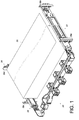
FIG. 1 is a schematic drawing in which the cable management assembly in an embodiment of the present invention is mounted to a pair of slide rail assemblies carrying an object; -
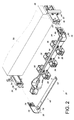
FIG. 2 is a schematic exploded view of the cable management assembly and the slide rail assemblies inFIG. 1 ; -
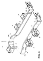
FIG. 3 is a schematic exploded view of the cable management assembly inFIG. 1 ; -
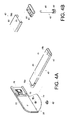
FIG. 4A is a schematic exploded view of the supporting member and the supporting base inFIG. 1 ; -
FIG. 4B is a schematic exploded view of the supporting member and the actuator inFIG. 1 ; -
FIG. 5 schematically shows a state in which the first cable management bracket and the second cable management bracket of the cable management assembly in an embodiment of the present invention are close to each other and the supporting member lies below both the first cable management bracket and the second cable management bracket; -
FIG. 6 schematically shows how the second cable management bracket of the cable management assembly inFIG. 5 is extended relative to the first cable management bracket and thereby rotates the supporting member relative to the supporting base when a second rail of a slide rail assembly is pulled out relative to a first rail of the slide rail assembly; -
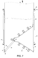
FIG. 7 schematically shows how the second cable management bracket of the cable management assembly inFIG. 6 is further extended relative to the first cable management bracket and thus further rotates the supporting member relative to the supporting base when the second rail of the slide rail assembly is further pulled out relative to the first rail; -
FIG. 8 schematically shows how the first cable management bracket and the second cable management bracket of the cable management assembly inFIG. 7 are brought closer to each other by the second rail of the slide rail assembly when the second rail is retracted with respect to the first rail; -
FIG. 9 schematically shows how the first cable management bracket and the second cable management bracket of the cable management assembly inFIG. 8 are brought even closer to each other by the second rail of the slide rail assembly when the second rail is further retracted with respect to the first rail; -
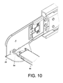
FIG. 10 schematically shows how an elastic member of the cable management assembly in an embodiment of the present invention is mounted between the supporting member and the supporting base; -
FIG. 11 schematically shows how the first cable management bracket and the second cable management bracket of the cable management assembly in an embodiment of the present invention are directly pivotally connected to each other; -
FIG. 12 is a schematic perspective view of the supporting base of the cable management assembly in an embodiment of the present invention; -
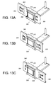
FIG. 13A schematically shows how the positioning element of the adjusting member of the cable management assembly inFIG. 12 is correspondingly engaged in the first positioning hole of the supporting base; -
FIG. 13B schematically shows how the adjusting member of the cable management assembly inFIG. 12 is adjusted, i.e., displaced, with respect to the supporting base; -
FIG. 13C schematically shows how the positioning element of the adjusting member of the cable management assembly inFIG. 12 is correspondingly engaged in the second positioning hole of the supporting base; -
FIG. 14A is a schematic sectional view showing how the positioning element of the adjusting member of the cable management assembly inFIG. 12 is correspondingly engaged in the first positioning hole of the supporting base; -
FIG. 14B is a schematic sectional view showing how a force is applied through the first positioning hole to the positioning element of the adjusting member of the cable management assembly inFIG. 12 ; -
FIG. 14C is a schematic sectional view showing how the adjusting member of the cable management assembly inFIG. 12 is adjusted, i.e., displaced, with respect to the supporting base; -
FIG. 14D is a schematic sectional view showing how the positioning element of the adjusting member of the cable management assembly inFIG. 12 is correspondingly engaged in the second positioning hole of the supporting base; and -
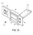
FIG. 15 schematically shows the supporting base of the cable management assembly in another embodiment of the present invention. - Referring to
FIG. 1 , thecable management assembly 20 according to an embodiment of the present invention is mounted to a pair of slide rail assemblies, which includes a firstslide rail assembly 22 and a secondslide rail assembly 24. Theslide rail assemblies rack 26, and thecable management assembly 20 is configured to be mounted to therack 26 by way of theslide rail assemblies rack 26 includes afirst post 28a, asecond post 28b, athird post 28c, and afourth post 28d. The firstslide rail assembly 22 is mounted between thefirst post 28a and thesecond post 28b while the secondslide rail assembly 24 is mounted between thethird post 28c and thefourth post 28d. The firstslide rail assembly 22 generally corresponds in position to the secondslide rail assembly 24. When in use, an object 30 (e.g., a server, storage device, or other electronic device) can be mounted between the firstslide rail assembly 22 and the secondslide rail assembly 24 in order for thecable management assembly 20 to keep the cables (not shown) of theobject 30 in neat arrangement. - As shown in
FIG. 2 , thecable management assembly 20 includes a firstcable management bracket 32, a secondcable management bracket 34 connected to the firstcable management bracket 32, a plurality ofcable supporting features 36, a supportingbase 38, a supportingmember 40, and anactuator 42. The firstslide rail assembly 22 at least includes afirst rail 44 and asecond rail 46 which can be longitudinally displaced relative to thefirst rail 44. Thefirst rail 44 is provided with a connectingbase 48, and thesecond rail 46 is provided with a connectingbase 50. The secondslide rail assembly 24 includes afirst rail 52 and asecond rail 54 which can be longitudinally displaced relative to thefirst rail 52. Thefirst rail 52 is provided with a connectingbase 56. - As shown in
FIG. 2 andFIG. 3 , the firstcable management bracket 32 includes acable management arm 58 and a mountingbracket 60. Thecable management arm 58 has afirst end 62a and asecond end 62b corresponding in position to thefirst end 62a. The mountingbracket 60 is pivotally connected to thecable management arm 58 at a position adjacent to thesecond end 62b. When in use, the firstcable management bracket 32 is connected to the connectingbase 48 of thefirst rail 44 of the firstslide rail assembly 22 via the mountingbracket 60. The secondcable management bracket 34, on the other hand, includes acable management arm 64 and a mountingbracket 66. Thecable management arm 64 has afirst end 68a and asecond end 68b corresponding in position to thefirst end 68a. In this embodiment, thecable management assembly 20 further includes anintermediate bracket 70 connected between thefirst end 62a of thecable management arm 58 of the firstcable management bracket 32 and thefirst end 68a of thecable management arm 64 of the secondcable management bracket 34. The mountingbracket 66 is pivotally connected to thecable management arm 64 at a position adjacent to thesecond end 68b. When in use, the secondcable management bracket 34 is connected to the connectingbase 50 of thesecond rail 46 of the firstslide rail assembly 22 via the mountingbracket 66. The plurality ofcable supporting features 36 serve to keep the cables (not shown) of theobject 30 in order. The cable supporting features 36 are connected to the firstcable management bracket 32 and the secondcable management bracket 34. -
FIG. 4A shows how the supportingbase 38 and the supportingmember 40 are arranged with respect to each other. As shown in the drawing, the supportingbase 38 has asidewall 72 and abase portion 74 generally perpendicularly connected to thesidewall 72. Thesidewall 72 is provided with a mountingbracket 76. When in use, referring toFIG. 2 , the supportingbase 38 is connected to the connectingbase 56 of thefirst rail 52 of the secondslide rail assembly 24 via the mountingbracket 76. The supportingmember 40 has afirst end 78a, asecond end 78b corresponding in position to thefirst end 78a, and amain body 80 connected between thefirst end 78a and thesecond end 78b. Thefirst end 78a of the supportingmember 40 is pivotally connected to thebase portion 74 of the supportingbase 38 via a pivotal connectingelement 82 so that the supportingmember 40 can rotate freely relative to thebase portion 74 of the supportingbase 38. In this embodiment, thebase portion 74 of the supportingbase 38 further has a blockingmember 75 for limiting the angle by which the supportingmember 40 can be rotated relative to thebase portion 74 of the supportingbase 38. - Referring to
FIG. 4B , theactuator 42 in this embodiment is mounted via an engaging member 84 to the supportingmember 40 at a position adjacent to thesecond end 78b. Theactuator 42, which is mounted to the supportingmember 40, can be viewed as a part of the supportingmember 40. More specifically, theactuator 42 has ahead 86 and abody 88 extending from thehead 86. The engaging member 84 has ahole 90, and thesecond end 78b of the supportingmember 40 also has ahole 92. Thebody 88 of the actuator 42 passes the twoholes actuator 42 is mounted to the supportingmember 40 at a position adjacent to thesecond end 78b and stands upright with respect to themain body 80 of the supportingmember 40. - In
FIG. 5 , the firstslide rail assembly 22 and the secondslide rail assembly 24 are mounted to therack 26 and are located within therack 26. The firstcable management bracket 32 of thecable management assembly 20 is mounted to thefirst rail 44 of the firstslide rail assembly 22 while the secondcable management bracket 34 is mounted to thesecond rail 46 of the firstslide rail assembly 22. The supportingbase 38 is mounted to thefirst rail 52 of the secondslide rail assembly 24. In addition, theobject 30 is mounted between thesecond rail 46 of the firstslide rail assembly 22 and thesecond rail 54 of the secondslide rail assembly 24. In the foregoing arrangement, the firstcable management bracket 32 and the secondcable management bracket 34 are close to each other, and the supportingmember 40 lies below both the firstcable management bracket 32 and the secondcable management bracket 34. When the firstcable management bracket 32 and the secondcable management bracket 34 are so loaded with cables that they move downward with respect to the supportingmember 40, the supportingmember 40 can support at least one of the firstcable management bracket 32 and the secondcable management bracket 34. On the other hand, theactuator 42 corresponds to the firstcable management bracket 32 and the secondcable management bracket 34. In this embodiment, theactuator 42 corresponds to and is located between the firstcable management bracket 32 and the secondcable management bracket 34. Referring toFIG. 6 , in the course in which theobject 30 is pulled out from therack 26 toward a first position P1, thesecond rail 46 of thefirst slide assembly 22 is displaced from a retracted position toward an extended position relative to thefirst rail 44 and therefore drives the firstcable management bracket 32 and the secondcable management bracket 34 of thecable management assembly 20 to extend. The firstcable management bracket 32 in turn drives a portion (e.g., the actuator 42) of the supportingmember 40 such that the supportingmember 40 is rotated from an initial position by a first angle θ1 with respect to the supportingbase 38. Thereby a portion of the firstcable management bracket 32 lies on a portion of the supportingmember 40 that is adjacent to theactuator 42. Thus, the supportingmember 40 in this state effectively supports the firstcable management bracket 32 and the secondcable management bracket 34 of thecable management assembly 20. - Referring to
FIG. 7 , in the course in which theobject 30 is pulled from the first position P1 toward a second position P2, the firstcable management bracket 32 and the secondcable management bracket 34 of thecable management assembly 20 are driven to extend further by thesecond rail 46 of the firstslide rail assembly 22 and in turn drive theactuator 42 further such that the supportingmember 40 is rotated from the position where it is at the first angle θ1 with respect to the supportingbase 38 to another position, where the supportingmember 40 is at a second angle θ2 with respect to the supportingbase 38 and is pressed against the blockingmember 75 of the supportingbase 38. In this state, a portion of the firstcable management bracket 32 still lies on the supportingmember 40 at a position adjacent to theactuator 42, so the supportingmember 40 keeps supporting the firstcable management bracket 32 and the secondcable management bracket 34 of thecable management assembly 20 effectively. -
FIG. 8 andFIG. 9 show how theobject 30 is pushed back into therack 26. In the process, the firstcable management bracket 32 and the secondcable management bracket 34 of thecable management assembly 20 are brought closer to each other by thesecond rail 46 of the firstslide rail assembly 22, and the secondcable management bracket 34 drives theactuator 42 in such a way that the supportingmember 40 is rotated relative to the supportingbase 38 and displaced toward the initial position. Eventually, thecable management assembly 20 can be folded to the state shown inFIG. 5 . - Referring to
FIG. 10 , the present embodiment further includes anelastic member 94 configured to provide an elastic force when the supportingmember 40 is rotated relative to the supportingbase 38. The supportingmember 40 can respond to the elastic force and therefore rotates readily with respect to the supportingbase 38. -
FIG. 11 shows the cable management assembly according to another embodiment of the present invention. In this embodiment, thecable management arm 202 of the firstcable management bracket 200 is directly pivotally connected to thecable management arm 206 of the secondcable management bracket 204 such that the firstcable management bracket 200 and the secondcable management bracket 204 are pivotally connected. In other words, this embodiment and the previous embodiment (seeFIG. 3 ) illustrate two feasible relationships between the cable management brackets, namely direct pivotal connection and indirect pivotal connection via theintermediate bracket 70. The present invention imposes no limitations in this regard. -
FIG. 12 ,FIGS. 13A∼ 13C , andFIGS. 14A∼14D show the structure of the supporting base in yet another embodiment of the present invention. In this embodiment, the supportingbase 300 includes an adjustingmember 302 movably connected to the supportingbase 300. The adjustingmember 302 includes afirst bracket 304, asecond bracket 306, and apositioning element 308 elastically mounted to one of thefirst bracket 304 and thesecond bracket 306. The supportingbase 300 has afirst positioning hole 310 and asecond positioning hole 312, both of which correspond to thepositioning element 308. When thepositioning element 308 is engaged, and therefore fixed in position, in thefirst positioning hole 310 of the supportingbase 300, the supportingbase 300 can be connected to the connectingbase 56 of thefirst rail 52 of the aforesaid secondslide rail assembly 24 via thefirst bracket 304, as shown inFIG. 2 . To operate (i.e., displace) thepositioning element 308, referring toFIG. 14B , a force F1 is applied to move thepositioning element 308 out of thefirst positioning hole 310 of the supportingbase 300, and a force F2 is applied to displace the adjustingmember 302, as shown inFIG. 14C , so that thepositioning element 308 is engaged in thesecond positioning hole 312 of the supportingbase 300 and secured in position, as shown inFIG. 14D . The supportingbase 300 in this configuration can be connected to the connectingbase 48 of thefirst rail 44 of the aforesaid firstslide rail assembly 22 via thesecond bracket 306. In this embodiment, therefore, the cable management brackets and the supporting base can be selectively and respectively connected to the slide rail assemblies according to actual installation needs. -
FIG. 15 show the structure of the supporting base in still another embodiment of the present invention. In this embodiment, the supportingbase 400 includes an adjustingmember 402 movably connected to the supportingbase 400. The adjustingmember 402 includes afirst bracket 404, asecond bracket 406, and a threadedhole 408 provided between thefirst bracket 404 and thesecond bracket 406. The supportingbase 400 has aslot 410, and a portion of theslot 410 corresponds in position to the threadedhole 408. A threadedelement 412 is passed through theslot 410, connected with the threadedhole 408, and thereby fixed in position. For adjustment, the threadedelement 412 is loosened so that the adjustingmember 402 can be moved relative to the supportingbase 400. Therefore, the cable management brackets and the supporting base in this embodiment can also be selectively and respectively connected to the slide rail assemblies to meet actual installation needs. - While the present invention has been disclosed herein by way of the preferred embodiments described above, the embodiments are not intended to be restrictive of the present invention. The scope of patent protection sought by the applicant is defined by the appended claims.
Claims (10)
- A cable management assembly (20), comprising:a first cable management bracket (32, 200);a second cable management bracket (34, 204) connected to the first cable management bracket (32, 200);a plurality of cable supporting features (36) connected to the first cable management bracket (32, 200) and the second cable management bracket (34, 204);a supporting base (38, 300, 400);a supporting member (40) pivotally connected to the supporting base (38, 300, 400) and configured for supporting at least one of the first cable management bracket (32, 200) and the second cable management bracket (34, 204); andan actuator (42) connected to the supporting member (40) andcorresponding to the first cable management bracket (32, 200) and the second cable management bracket (34, 204);wherein upon relative displacement of the first cable management bracket (32, 200) and the second cable management bracket (34, 204), one of the first cable management bracket (32, 200) and the second cable management bracket (34, 204) drives the supporting member (40) to rotate relative to the supporting base (38, 300, 400).
- The cable management assembly (20) as claimed in claim 1, wherein the cable management assembly (20) is to be mounted to a pair of slide rail assemblies (22, 24) including a first slide rail assembly (22) and a second slide rail assembly (24) and is mountable to a rack (26) via the pair of slide rail assemblies (22, 24), the first slide rail assembly (22) including a first rail (44) and a second rail (46) longitudinally displaceable relative to the first rail (44); the first cable management bracket (32, 200) is adapted to be connected to the first rail (44) of the first slide rail assembly (22), the second cable management bracket (34, 204) is adapted to be connected to the second rail (46) of the first slide rail assembly (22), and the supporting base (38, 300, 400) is adapted to be connected to the second slide rail assembly (24); when the second rail (46) of the first slide rail assembly (22) is displaced relative to the first rail (44) of the first slide rail assembly (22) from a retracted position toward an extended position, the second cable management bracket (34, 204) displaces the first cable management bracket (32, 200) such that the first cable management bracket (32, 200) drives the actuator (42) and thereby rotates the supporting member (40) relative to the supporting base (38, 300, 400) by an angle; and when the second rail (46) of the first slide rail assembly (22) is displaced relative to the first rail (44) of the first slide rail assembly (22) from the extended position toward the retracted position, the second cable management bracket (34, 204) drives the actuator (42) and thereby rotates the supporting member (40) relative to the supporting base (38, 300, 400) toward an initial position of the supporting member (40).
- The cable management assembly (20) as claimed in claim 2, wherein the first cable management bracket (32, 200) includes a cable management arm (58, 202) having a first end (62a) and a second end (62b), the second cable management bracket (34, 204) includes a cable management arm (64, 206) having a first end (68a) and a second end (68b), and the cable management assembly (20) further comprises an intermediate bracket (70) pivotally connected between the first end (62a) of the cable management arm (58, 202) of the first cable management bracket (32, 200) and the first end (68a) of the cable management arm (64, 206) of the second cable management bracket (34, 204).
- The cable management assembly (20) as claimed in claim 3, further comprising a first mounting bracket (60) pivotally connected to the second end (62b) of the cable management arm (58, 202) of the first cable management bracket (32, 200), the first cable management bracket (32, 200) being connectable to the first rail (44) of the first slide rail assembly (22) via the first mounting bracket (60); and a second mounting bracket (66) pivotally connected to the second end (68b) of the cable management arm (64, 206) of the second cable management bracket (34, 204), the second cable management bracket (34, 204) being connectable to the second rail (46) of the first slide rail assembly (22) via the second mounting bracket (66).
- The cable management assembly (20) as claimed in claim 2, wherein the supporting base (38, 300, 400) has a sidewall (72) and a base portion (74) generally perpendicularly connected to the sidewall (72), and the sidewall (72) is provided with a third mounting bracket (76), the supporting base (38, 300, 400) being connectable to the second slide rail assembly (24) via the third mounting bracket (76).
- The cable management assembly (20) as claimed in claim 5, wherein the base portion (74) of the supporting base (38, 300, 400) has a blocking member (75) for limiting an angle by which the supporting member (40) is allowed to be rotated relative to the base portion (74) of the supporting base (38, 300, 400).
- The cable management assembly (20) as claimed in claim 1 or 2, wherein the supporting member (40) has a first end (78a), a second end (78b) corresponding in position to the first end (78a), and a main body (80) connected between the first end (78a) and the second end (78b) of the supporting member (40); the first end (78a) of the supporting member (40) is pivotally connected to the supporting base (38, 300, 400) via a pivotal connecting element (82) such that the supporting member (40) is freely rotatable relative to the supporting base (38, 300, 400); and the actuator (42) is mounted to the second end (78b) of the supporting member (40) via an engaging member (84) and is thereby rendered upright with respect to the main body (80) of the supporting member (40).
- The cable management assembly (20) as claimed in claim 1 or 2, further comprising an elastic member (94) for providing an elastic force when the supporting member (40) is rotated relative to the supporting base (38, 300, 400), wherein the supporting member (40) is able to respond to the elastic force and therefore be rotated relative to the supporting base (38, 300, 400) with ease.
- The cable management assembly (20) as claimed in claim 1 or 2, wherein the supporting base (300) comprises an adjusting member (302) movably connected to the supporting base (300); the adjusting member (302) includes a first bracket (304), a second bracket (306), and a positioning element (308) elastically mounted to one of the first bracket (304) and the second bracket (306); and the supporting base (300) has a first positioning hole (310) and a second positioning hole (312), the first positioning hole (310) and the second positioning hole (312) both corresponding to the positioning element (308).
- The cable management assembly (20) as claimed in claim 1 or 2, wherein the supporting base (400) comprises an adjusting member (402) movably connected to the supporting base (400); the adjusting member (402) includes a first bracket (404), a second bracket (406), and a threaded hole (408) provided between the first bracket (404) and the second bracket (406); and the supporting base (400) has a slot (410) having a portion corresponding in position to the threaded hole (408) so that a threaded element (412) can pass through the slot (410), connect with the threaded hole (408), and thus be fixed in position.
Priority Applications (1)
| Application Number | Priority Date | Filing Date | Title |
|---|---|---|---|
| EP15152801.5A EP3051929B1 (en) | 2015-01-28 | 2015-01-28 | Cable management assembly |
Applications Claiming Priority (1)
| Application Number | Priority Date | Filing Date | Title |
|---|---|---|---|
| EP15152801.5A EP3051929B1 (en) | 2015-01-28 | 2015-01-28 | Cable management assembly |
Publications (2)
| Publication Number | Publication Date |
|---|---|
| EP3051929A1 true EP3051929A1 (en) | 2016-08-03 |
| EP3051929B1 EP3051929B1 (en) | 2019-12-04 |
Family
ID=52396583
Family Applications (1)
| Application Number | Title | Priority Date | Filing Date |
|---|---|---|---|
| EP15152801.5A Active EP3051929B1 (en) | 2015-01-28 | 2015-01-28 | Cable management assembly |
Country Status (1)
| Country | Link |
|---|---|
| EP (1) | EP3051929B1 (en) |
Cited By (4)
| Publication number | Priority date | Publication date | Assignee | Title |
|---|---|---|---|---|
| CN106598174A (en) * | 2016-12-22 | 2017-04-26 | 广东星徽精密制造股份有限公司 | Lid body positioned server line managing device |
| CN109429465A (en) * | 2017-08-22 | 2019-03-05 | 川湖科技股份有限公司 | Rack system, wire arranging device and connecting assembly |
| JP2020170494A (en) * | 2019-04-04 | 2020-10-15 | 廣達電脳股▲ふん▼有限公司 | Server with movable signal cable and cable sleeve |
| CN112702872A (en) * | 2019-10-22 | 2021-04-23 | 通用电气精准医疗有限责任公司 | Method and system for cable management |
Citations (8)
| Publication number | Priority date | Publication date | Assignee | Title |
|---|---|---|---|---|
| US7472795B2 (en) | 2003-12-05 | 2009-01-06 | Pentair Electronic Packaging Company | Anti-sag management assembly |
| US7554819B2 (en) | 2004-10-15 | 2009-06-30 | King Slide Works Co., Ltd. | Cable management arm assembly |
| US7712615B2 (en) | 2004-10-15 | 2010-05-11 | King Slide Works Co., Ltd. | Support slide assembly for cable management arm |
| US20100193646A1 (en) * | 2008-09-03 | 2010-08-05 | King Slide Works Co., Ltd. | Support slide assembly for a cable management arm |
| US8251321B2 (en) | 2007-07-11 | 2012-08-28 | King Slide Works Co., Ltd. | Cable management arm connection system |
| US20140158646A1 (en) | 2012-12-07 | 2014-06-12 | King Slide Technology Co., Ltd. | Cable management arm |
| US20140158834A1 (en) | 2012-12-07 | 2014-06-12 | King Slide Technology Co., Ltd. | Cable management device |
| US20140183306A1 (en) | 2012-12-07 | 2014-07-03 | King Slide Works Co., Ltd. | Cable management arm assembly |
-
2015
- 2015-01-28 EP EP15152801.5A patent/EP3051929B1/en active Active
Patent Citations (9)
| Publication number | Priority date | Publication date | Assignee | Title |
|---|---|---|---|---|
| US7472795B2 (en) | 2003-12-05 | 2009-01-06 | Pentair Electronic Packaging Company | Anti-sag management assembly |
| US7554819B2 (en) | 2004-10-15 | 2009-06-30 | King Slide Works Co., Ltd. | Cable management arm assembly |
| US7712615B2 (en) | 2004-10-15 | 2010-05-11 | King Slide Works Co., Ltd. | Support slide assembly for cable management arm |
| US8251321B2 (en) | 2007-07-11 | 2012-08-28 | King Slide Works Co., Ltd. | Cable management arm connection system |
| US20100193646A1 (en) * | 2008-09-03 | 2010-08-05 | King Slide Works Co., Ltd. | Support slide assembly for a cable management arm |
| US8231014B2 (en) | 2008-09-03 | 2012-07-31 | King Slide Works Co., Ltd. | Support slide assembly for a cable management arm |
| US20140158646A1 (en) | 2012-12-07 | 2014-06-12 | King Slide Technology Co., Ltd. | Cable management arm |
| US20140158834A1 (en) | 2012-12-07 | 2014-06-12 | King Slide Technology Co., Ltd. | Cable management device |
| US20140183306A1 (en) | 2012-12-07 | 2014-07-03 | King Slide Works Co., Ltd. | Cable management arm assembly |
Cited By (5)
| Publication number | Priority date | Publication date | Assignee | Title |
|---|---|---|---|---|
| CN106598174A (en) * | 2016-12-22 | 2017-04-26 | 广东星徽精密制造股份有限公司 | Lid body positioned server line managing device |
| CN109429465A (en) * | 2017-08-22 | 2019-03-05 | 川湖科技股份有限公司 | Rack system, wire arranging device and connecting assembly |
| CN109429465B (en) * | 2017-08-22 | 2020-06-02 | 川湖科技股份有限公司 | Rack systems, cable management and connection assemblies |
| JP2020170494A (en) * | 2019-04-04 | 2020-10-15 | 廣達電脳股▲ふん▼有限公司 | Server with movable signal cable and cable sleeve |
| CN112702872A (en) * | 2019-10-22 | 2021-04-23 | 通用电气精准医疗有限责任公司 | Method and system for cable management |
Also Published As
| Publication number | Publication date |
|---|---|
| EP3051929B1 (en) | 2019-12-04 |
Similar Documents
| Publication | Publication Date | Title |
|---|---|---|
| US9640961B2 (en) | Cable management assembly | |
| US8231014B2 (en) | Support slide assembly for a cable management arm | |
| US6945504B2 (en) | Adjustable cable management arm for furniture | |
| US9144174B2 (en) | Cable management arm assembly | |
| CN105682403B (en) | Wire management assembly | |
| EP3051929B1 (en) | Cable management assembly | |
| US8251321B2 (en) | Cable management arm connection system | |
| US8469303B2 (en) | Cable cord retractor | |
| US20130099080A1 (en) | Clamp window rods | |
| US8469304B2 (en) | System for storing multiple cable retractors | |
| US10333286B2 (en) | Slide rail assembly and cable management device thereof | |
| US9056744B2 (en) | Cable cord retractor | |
| US10645838B2 (en) | Slide rail assembly and cable management device thereof | |
| US20160205797A1 (en) | Table-mounted cord retractor | |
| US10709033B2 (en) | Coupling assembly and cable management device thereof | |
| CN105530794B (en) | Wire arranging frame | |
| US20050141180A1 (en) | Display unit with cord clamper | |
| TW202007311A (en) | Support assembly and cable management kit | |
| EP3666117B1 (en) | Bracket mounting structure | |
| JP3197090U (en) | Cable management kit | |
| US20140182081A1 (en) | Rack-stop structure for door | |
| EP3041329A1 (en) | Cable management arm | |
| TWI540279B (en) | Cable management assembly | |
| EP3030065A1 (en) | Cable management arm supporting device and mounting assembly thereof | |
| WO2014178534A1 (en) | A sliding device for a desk cable arrangement cover |
Legal Events
| Date | Code | Title | Description |
|---|---|---|---|
| PUAI | Public reference made under article 153(3) epc to a published international application that has entered the european phase |
Free format text: ORIGINAL CODE: 0009012 |
|
| 17P | Request for examination filed |
Effective date: 20160308 |
|
| AK | Designated contracting states |
Kind code of ref document: A1 Designated state(s): AL AT BE BG CH CY CZ DE DK EE ES FI FR GB GR HR HU IE IS IT LI LT LU LV MC MK MT NL NO PL PT RO RS SE SI SK SM TR |
|
| AX | Request for extension of the european patent |
Extension state: BA ME |
|
| STAA | Information on the status of an ep patent application or granted ep patent |
Free format text: STATUS: EXAMINATION IS IN PROGRESS |
|
| 17Q | First examination report despatched |
Effective date: 20170915 |
|
| GRAP | Despatch of communication of intention to grant a patent |
Free format text: ORIGINAL CODE: EPIDOSNIGR1 |
|
| STAA | Information on the status of an ep patent application or granted ep patent |
Free format text: STATUS: GRANT OF PATENT IS INTENDED |
|
| INTG | Intention to grant announced |
Effective date: 20190702 |
|
| GRAS | Grant fee paid |
Free format text: ORIGINAL CODE: EPIDOSNIGR3 |
|
| GRAA | (expected) grant |
Free format text: ORIGINAL CODE: 0009210 |
|
| STAA | Information on the status of an ep patent application or granted ep patent |
Free format text: STATUS: THE PATENT HAS BEEN GRANTED |
|
| AK | Designated contracting states |
Kind code of ref document: B1 Designated state(s): AL AT BE BG CH CY CZ DE DK EE ES FI FR GB GR HR HU IE IS IT LI LT LU LV MC MK MT NL NO PL PT RO RS SE SI SK SM TR |
|
| REG | Reference to a national code |
Ref country code: GB Ref legal event code: FG4D |
|
| REG | Reference to a national code |
Ref country code: CH Ref legal event code: EP |
|
| REG | Reference to a national code |
Ref country code: AT Ref legal event code: REF Ref document number: 1211208 Country of ref document: AT Kind code of ref document: T Effective date: 20191215 |
|
| REG | Reference to a national code |
Ref country code: DE Ref legal event code: R096 Ref document number: 602015042796 Country of ref document: DE |
|
| REG | Reference to a national code |
Ref country code: IE Ref legal event code: FG4D |
|
| REG | Reference to a national code |
Ref country code: NL Ref legal event code: MP Effective date: 20191204 |
|
| REG | Reference to a national code |
Ref country code: LT Ref legal event code: MG4D |
|
| PG25 | Lapsed in a contracting state [announced via postgrant information from national office to epo] |
Ref country code: SE Free format text: LAPSE BECAUSE OF FAILURE TO SUBMIT A TRANSLATION OF THE DESCRIPTION OR TO PAY THE FEE WITHIN THE PRESCRIBED TIME-LIMIT Effective date: 20191204 Ref country code: LV Free format text: LAPSE BECAUSE OF FAILURE TO SUBMIT A TRANSLATION OF THE DESCRIPTION OR TO PAY THE FEE WITHIN THE PRESCRIBED TIME-LIMIT Effective date: 20191204 Ref country code: BG Free format text: LAPSE BECAUSE OF FAILURE TO SUBMIT A TRANSLATION OF THE DESCRIPTION OR TO PAY THE FEE WITHIN THE PRESCRIBED TIME-LIMIT Effective date: 20200304 Ref country code: FI Free format text: LAPSE BECAUSE OF FAILURE TO SUBMIT A TRANSLATION OF THE DESCRIPTION OR TO PAY THE FEE WITHIN THE PRESCRIBED TIME-LIMIT Effective date: 20191204 Ref country code: NO Free format text: LAPSE BECAUSE OF FAILURE TO SUBMIT A TRANSLATION OF THE DESCRIPTION OR TO PAY THE FEE WITHIN THE PRESCRIBED TIME-LIMIT Effective date: 20200304 Ref country code: LT Free format text: LAPSE BECAUSE OF FAILURE TO SUBMIT A TRANSLATION OF THE DESCRIPTION OR TO PAY THE FEE WITHIN THE PRESCRIBED TIME-LIMIT Effective date: 20191204 |
|
| PG25 | Lapsed in a contracting state [announced via postgrant information from national office to epo] |
Ref country code: RS Free format text: LAPSE BECAUSE OF FAILURE TO SUBMIT A TRANSLATION OF THE DESCRIPTION OR TO PAY THE FEE WITHIN THE PRESCRIBED TIME-LIMIT Effective date: 20191204 Ref country code: HR Free format text: LAPSE BECAUSE OF FAILURE TO SUBMIT A TRANSLATION OF THE DESCRIPTION OR TO PAY THE FEE WITHIN THE PRESCRIBED TIME-LIMIT Effective date: 20191204 |
|
| PG25 | Lapsed in a contracting state [announced via postgrant information from national office to epo] |
Ref country code: AL Free format text: LAPSE BECAUSE OF FAILURE TO SUBMIT A TRANSLATION OF THE DESCRIPTION OR TO PAY THE FEE WITHIN THE PRESCRIBED TIME-LIMIT Effective date: 20191204 |
|
| PG25 | Lapsed in a contracting state [announced via postgrant information from national office to epo] |
Ref country code: PT Free format text: LAPSE BECAUSE OF FAILURE TO SUBMIT A TRANSLATION OF THE DESCRIPTION OR TO PAY THE FEE WITHIN THE PRESCRIBED TIME-LIMIT Effective date: 20200429 Ref country code: ES Free format text: LAPSE BECAUSE OF FAILURE TO SUBMIT A TRANSLATION OF THE DESCRIPTION OR TO PAY THE FEE WITHIN THE PRESCRIBED TIME-LIMIT Effective date: 20191204 Ref country code: RO Free format text: LAPSE BECAUSE OF FAILURE TO SUBMIT A TRANSLATION OF THE DESCRIPTION OR TO PAY THE FEE WITHIN THE PRESCRIBED TIME-LIMIT Effective date: 20191204 Ref country code: NL Free format text: LAPSE BECAUSE OF FAILURE TO SUBMIT A TRANSLATION OF THE DESCRIPTION OR TO PAY THE FEE WITHIN THE PRESCRIBED TIME-LIMIT Effective date: 20191204 Ref country code: CZ Free format text: LAPSE BECAUSE OF FAILURE TO SUBMIT A TRANSLATION OF THE DESCRIPTION OR TO PAY THE FEE WITHIN THE PRESCRIBED TIME-LIMIT Effective date: 20191204 Ref country code: EE Free format text: LAPSE BECAUSE OF FAILURE TO SUBMIT A TRANSLATION OF THE DESCRIPTION OR TO PAY THE FEE WITHIN THE PRESCRIBED TIME-LIMIT Effective date: 20191204 |
|
| PG25 | Lapsed in a contracting state [announced via postgrant information from national office to epo] |
Ref country code: IS Free format text: LAPSE BECAUSE OF FAILURE TO SUBMIT A TRANSLATION OF THE DESCRIPTION OR TO PAY THE FEE WITHIN THE PRESCRIBED TIME-LIMIT Effective date: 20200404 Ref country code: SK Free format text: LAPSE BECAUSE OF FAILURE TO SUBMIT A TRANSLATION OF THE DESCRIPTION OR TO PAY THE FEE WITHIN THE PRESCRIBED TIME-LIMIT Effective date: 20191204 Ref country code: SM Free format text: LAPSE BECAUSE OF FAILURE TO SUBMIT A TRANSLATION OF THE DESCRIPTION OR TO PAY THE FEE WITHIN THE PRESCRIBED TIME-LIMIT Effective date: 20191204 |
|
| REG | Reference to a national code |
Ref country code: CH Ref legal event code: PL |
|
| REG | Reference to a national code |
Ref country code: DE Ref legal event code: R097 Ref document number: 602015042796 Country of ref document: DE |
|
| REG | Reference to a national code |
Ref country code: AT Ref legal event code: MK05 Ref document number: 1211208 Country of ref document: AT Kind code of ref document: T Effective date: 20191204 |
|
| PG25 | Lapsed in a contracting state [announced via postgrant information from national office to epo] |
Ref country code: MC Free format text: LAPSE BECAUSE OF FAILURE TO SUBMIT A TRANSLATION OF THE DESCRIPTION OR TO PAY THE FEE WITHIN THE PRESCRIBED TIME-LIMIT Effective date: 20191204 |
|
| PLBE | No opposition filed within time limit |
Free format text: ORIGINAL CODE: 0009261 |
|
| STAA | Information on the status of an ep patent application or granted ep patent |
Free format text: STATUS: NO OPPOSITION FILED WITHIN TIME LIMIT |
|
| REG | Reference to a national code |
Ref country code: BE Ref legal event code: MM Effective date: 20200131 |
|
| PG25 | Lapsed in a contracting state [announced via postgrant information from national office to epo] |
Ref country code: LU Free format text: LAPSE BECAUSE OF NON-PAYMENT OF DUE FEES Effective date: 20200128 Ref country code: DK Free format text: LAPSE BECAUSE OF FAILURE TO SUBMIT A TRANSLATION OF THE DESCRIPTION OR TO PAY THE FEE WITHIN THE PRESCRIBED TIME-LIMIT Effective date: 20191204 Ref country code: FR Free format text: LAPSE BECAUSE OF NON-PAYMENT OF DUE FEES Effective date: 20200204 |
|
| 26N | No opposition filed |
Effective date: 20200907 |
|
| PG25 | Lapsed in a contracting state [announced via postgrant information from national office to epo] |
Ref country code: SI Free format text: LAPSE BECAUSE OF FAILURE TO SUBMIT A TRANSLATION OF THE DESCRIPTION OR TO PAY THE FEE WITHIN THE PRESCRIBED TIME-LIMIT Effective date: 20191204 Ref country code: CH Free format text: LAPSE BECAUSE OF NON-PAYMENT OF DUE FEES Effective date: 20200131 Ref country code: AT Free format text: LAPSE BECAUSE OF FAILURE TO SUBMIT A TRANSLATION OF THE DESCRIPTION OR TO PAY THE FEE WITHIN THE PRESCRIBED TIME-LIMIT Effective date: 20191204 Ref country code: LI Free format text: LAPSE BECAUSE OF NON-PAYMENT OF DUE FEES Effective date: 20200131 Ref country code: BE Free format text: LAPSE BECAUSE OF NON-PAYMENT OF DUE FEES Effective date: 20200131 Ref country code: PL Free format text: LAPSE BECAUSE OF FAILURE TO SUBMIT A TRANSLATION OF THE DESCRIPTION OR TO PAY THE FEE WITHIN THE PRESCRIBED TIME-LIMIT Effective date: 20191204 |
|
| PG25 | Lapsed in a contracting state [announced via postgrant information from national office to epo] |
Ref country code: IT Free format text: LAPSE BECAUSE OF FAILURE TO SUBMIT A TRANSLATION OF THE DESCRIPTION OR TO PAY THE FEE WITHIN THE PRESCRIBED TIME-LIMIT Effective date: 20191204 |
|
| PG25 | Lapsed in a contracting state [announced via postgrant information from national office to epo] |
Ref country code: TR Free format text: LAPSE BECAUSE OF FAILURE TO SUBMIT A TRANSLATION OF THE DESCRIPTION OR TO PAY THE FEE WITHIN THE PRESCRIBED TIME-LIMIT Effective date: 20191204 Ref country code: MT Free format text: LAPSE BECAUSE OF FAILURE TO SUBMIT A TRANSLATION OF THE DESCRIPTION OR TO PAY THE FEE WITHIN THE PRESCRIBED TIME-LIMIT Effective date: 20191204 Ref country code: CY Free format text: LAPSE BECAUSE OF FAILURE TO SUBMIT A TRANSLATION OF THE DESCRIPTION OR TO PAY THE FEE WITHIN THE PRESCRIBED TIME-LIMIT Effective date: 20191204 |
|
| PG25 | Lapsed in a contracting state [announced via postgrant information from national office to epo] |
Ref country code: MK Free format text: LAPSE BECAUSE OF FAILURE TO SUBMIT A TRANSLATION OF THE DESCRIPTION OR TO PAY THE FEE WITHIN THE PRESCRIBED TIME-LIMIT Effective date: 20191204 |
|
| PG25 | Lapsed in a contracting state [announced via postgrant information from national office to epo] |
Ref country code: GR Free format text: LAPSE BECAUSE OF FAILURE TO SUBMIT A TRANSLATION OF THE DESCRIPTION OR TO PAY THE FEE WITHIN THE PRESCRIBED TIME-LIMIT Effective date: 20191204 |
|
| PGFP | Annual fee paid to national office [announced via postgrant information from national office to epo] |
Ref country code: GB Payment date: 20251106 Year of fee payment: 12 |
|
| PGFP | Annual fee paid to national office [announced via postgrant information from national office to epo] |
Ref country code: IE Payment date: 20251106 Year of fee payment: 12 |
|
| PGFP | Annual fee paid to national office [announced via postgrant information from national office to epo] |
Ref country code: DE Payment date: 20251111 Year of fee payment: 12 |