EP3051839A1 - Sound generator - Google Patents
Sound generator Download PDFInfo
- Publication number
- EP3051839A1 EP3051839A1 EP14857082.3A EP14857082A EP3051839A1 EP 3051839 A1 EP3051839 A1 EP 3051839A1 EP 14857082 A EP14857082 A EP 14857082A EP 3051839 A1 EP3051839 A1 EP 3051839A1
- Authority
- EP
- European Patent Office
- Prior art keywords
- support part
- piezoelectric body
- body plate
- secured
- surface member
- Prior art date
- Legal status (The legal status is an assumption and is not a legal conclusion. Google has not performed a legal analysis and makes no representation as to the accuracy of the status listed.)
- Withdrawn
Links
Images


Classifications
-
- H—ELECTRICITY
- H04—ELECTRIC COMMUNICATION TECHNIQUE
- H04R—LOUDSPEAKERS, MICROPHONES, GRAMOPHONE PICK-UPS OR LIKE ACOUSTIC ELECTROMECHANICAL TRANSDUCERS; ELECTRIC HEARING AIDS; PUBLIC ADDRESS SYSTEMS
- H04R1/00—Details of transducers, loudspeakers or microphones
- H04R1/02—Casings; Cabinets ; Supports therefor; Mountings therein
- H04R1/026—Supports for loudspeaker casings
-
- H—ELECTRICITY
- H04—ELECTRIC COMMUNICATION TECHNIQUE
- H04R—LOUDSPEAKERS, MICROPHONES, GRAMOPHONE PICK-UPS OR LIKE ACOUSTIC ELECTROMECHANICAL TRANSDUCERS; ELECTRIC HEARING AIDS; PUBLIC ADDRESS SYSTEMS
- H04R17/00—Piezoelectric transducers; Electrostrictive transducers
-
- H—ELECTRICITY
- H04—ELECTRIC COMMUNICATION TECHNIQUE
- H04R—LOUDSPEAKERS, MICROPHONES, GRAMOPHONE PICK-UPS OR LIKE ACOUSTIC ELECTROMECHANICAL TRANSDUCERS; ELECTRIC HEARING AIDS; PUBLIC ADDRESS SYSTEMS
- H04R17/00—Piezoelectric transducers; Electrostrictive transducers
- H04R17/005—Piezoelectric transducers; Electrostrictive transducers using a piezoelectric polymer
-
- H—ELECTRICITY
- H04—ELECTRIC COMMUNICATION TECHNIQUE
- H04R—LOUDSPEAKERS, MICROPHONES, GRAMOPHONE PICK-UPS OR LIKE ACOUSTIC ELECTROMECHANICAL TRANSDUCERS; ELECTRIC HEARING AIDS; PUBLIC ADDRESS SYSTEMS
- H04R31/00—Apparatus or processes specially adapted for the manufacture of transducers or diaphragms therefor
- H04R31/006—Interconnection of transducer parts
-
- H—ELECTRICITY
- H04—ELECTRIC COMMUNICATION TECHNIQUE
- H04R—LOUDSPEAKERS, MICROPHONES, GRAMOPHONE PICK-UPS OR LIKE ACOUSTIC ELECTROMECHANICAL TRANSDUCERS; ELECTRIC HEARING AIDS; PUBLIC ADDRESS SYSTEMS
- H04R7/00—Diaphragms for electromechanical transducers; Cones
- H04R7/02—Diaphragms for electromechanical transducers; Cones characterised by the construction
- H04R7/04—Plane diaphragms
- H04R7/045—Plane diaphragms using the distributed mode principle, i.e. whereby the acoustic radiation is emanated from uniformly distributed free bending wave vibration induced in a stiff panel and not from pistonic motion
-
- H—ELECTRICITY
- H04—ELECTRIC COMMUNICATION TECHNIQUE
- H04R—LOUDSPEAKERS, MICROPHONES, GRAMOPHONE PICK-UPS OR LIKE ACOUSTIC ELECTROMECHANICAL TRANSDUCERS; ELECTRIC HEARING AIDS; PUBLIC ADDRESS SYSTEMS
- H04R2440/00—Bending wave transducers covered by H04R, not provided for in its groups
- H04R2440/05—Aspects relating to the positioning and way or means of mounting of exciters to resonant bending wave panels
-
- H—ELECTRICITY
- H04—ELECTRIC COMMUNICATION TECHNIQUE
- H04R—LOUDSPEAKERS, MICROPHONES, GRAMOPHONE PICK-UPS OR LIKE ACOUSTIC ELECTROMECHANICAL TRANSDUCERS; ELECTRIC HEARING AIDS; PUBLIC ADDRESS SYSTEMS
- H04R2499/00—Aspects covered by H04R or H04S not otherwise provided for in their subgroups
- H04R2499/10—General applications
- H04R2499/11—Transducers incorporated or for use in hand-held devices, e.g. mobile phones, PDA's, camera's
-
- H—ELECTRICITY
- H04—ELECTRIC COMMUNICATION TECHNIQUE
- H04R—LOUDSPEAKERS, MICROPHONES, GRAMOPHONE PICK-UPS OR LIKE ACOUSTIC ELECTROMECHANICAL TRANSDUCERS; ELECTRIC HEARING AIDS; PUBLIC ADDRESS SYSTEMS
- H04R2499/00—Aspects covered by H04R or H04S not otherwise provided for in their subgroups
- H04R2499/10—General applications
- H04R2499/15—Transducers incorporated in visual displaying devices, e.g. televisions, computer displays, laptops
Definitions
- This invention relates to a device generating sound.
- Patent Document 1 discloses an exciter in which a piezoelectric element is accommodated in a case.
- the exciter is attached to a cowl of a motorcycle, for example. Vibration from the exciter is transmitted to the cowl and makes the cowl vibrate as a vibration plate to generate a sound.
- the piezoelectric vibration unit is attached to a panel of a mobile phone, for example, and makes the panel vibrate as a vibration panel to generate a sound.
- One aspect of the present invention provides a device provided with a main surface member, a piezoelectric body plate, a first support part and a housing.
- the main surface member is used as a vibration plate.
- the piezoelectric body plate vibrates according to an electric signal.
- the first support part supports the piezoelectric body plate.
- the housing has a second support part that supports the main surface member and extends in a prescribed direction intersecting the main surface member.
- the first support part is secured to the second support part so that the second support part vibrates in the prescribed direction according to vibration of the piezoelectric body plate.
- the vibration of the piezoelectric body plate is transmitted to the main surface member via the first support part and the second support part, and due to this the main surface member vibrates to generate a sound.
- the device is an electronic device such as a mobile phone, a tablet or a PC.
- the main surface member is a glass plate forming a screen of the electric device, for example.
- the second support part is a side wall portion of the housing of the electric device or a portion supporting the glass plate.
- Another aspect of the present invention provides a device provided with a main surface member, a piezoelectric body plate, a first support part and a housing.
- the main surface member is used as a vibration plate.
- the piezoelectric body plate vibrates according to an electric signal.
- the first support part supports the piezoelectric body plate.
- the housing is distinct and separated from the main surface member.
- the housing has a second support part that supports the main surface member and extends in a prescribed direction intersecting the main surface member.
- the first support part is secured to the second support part. Vibration of the piezoelectric body plate is transmitted to the main surface member via the first support part and the second support part, and due to this the main surface member vibrates to generate a sound.
- the second support part is a part of the housing and extends in the prescribed direction. Making the second support part vibrate at least in the prescribed direction makes the main surface member vibrate to generate a sound. According to this approach, sufficient sound pressure can be obtained in comparison with a case where the exciter or the piezoelectric vibration unit is attached to the main surface member.
- the first support part supports the piezoelectric body plate and is secured to the second support part directly, it is unnecessary to provide separately a case for accommodating the piezoelectric body plate in the housing. In other words, it is unnecessary to reserve a large space for the piezoelectric body plate in the housing. Accordingly, even if the whole of the device is downsized and thinned, the structure generating a sound can be put in the housing.
- a device 10 according to a first embodiment of the present invention is provided with a main surface member 30 used as a vibrating plate, a piezoelectric body plate 40, a first support part 50 supporting the piezoelectric body plate 40 and a housing 20.
- the device 10 of the present embodiment is an electronic device such as a mobile phone, a tablet or a PC while the main surface member 30 is a glass plate constituting a screen of the electronic device, for example.
- the main surface member 30 is disposed to be parallel to a horizontal plane (an XY-plane).
- the housing 20 has a second support part 24 that supports the main surface member 30 and extends in a prescribed direction intersecting the main surface member 30.
- the prescribed direction is a vertical direction (or a Z-direction) perpendicular to the main surface member 30 while the second support part 24 is a side wall portion (or a part supporting the main surface member 30 formed of a glass plate) of the housing 20 of the electronic device.
- the housing 20 of the present embodiment is distinct and separated from the main surface member 30.
- the piezoelectric body plate 40 As illustrated in Fig. 2 , on the piezoelectric body plate 40, two external electrodes 60 and 62 are formed.
- the external electrodes 60 and 62 are supplied with an electric signal (or driving voltage) through conductors 66 and 68 formed on an FPC (Flexible Printed Circuit) 64.
- the piezoelectric body plate 40 vibrates according to the electric signal supplied.
- the piezoelectric body plate 40 has a longitudinal direction in an X-direction and a short-direction in a Y-direction, in the present embodiment.
- the piezoelectric body plate 40 Upon being supplied with the electric signal, the piezoelectric body plate 40 vibrates so that both ends of the piezoelectric body plate 40 in the longitudinal direction are moved in the vertical direction (the Z-direction).
- the piezoelectric body plate 40 of the present embodiment carries out bending motion, which is a standing wave having a traveling direction in the longitudinal direction and a maximum amplitude at the both ends in the longitudinal direction, according to the electric signal.
- the first support part 50 has a plate-like main support part 52 supporting the piezoelectric body plate 40 and a secured part 54 secured to the second support part 24.
- the main support part 52 has a longitudinal direction in the X-direction and a short-direction in the Y-direction.
- the secured part 54 is connected to the main support part 52 at a vicinity of one end of the longitudinal direction of the main support part 52.
- the secured part 54 is situated at the vicinity of the one end of the longitudinal direction of the main support part 52 and extends in the vertical direction from one end of the short-direction of the main support part 52.
- the secured part 54 is provided not to regulate vibration of the main support part 52 in the present embodiment.
- the first support part 50 of the present embodiment is made of fiber reinforced plastic.
- the first support part 50 is made of glass fiber reinforced polyamide resin.
- the present invention is not limited thereto.
- the first support part 50 may be formed by bending a metal sheet, for example. Resin, however, is preferable for material of the first support part 50 since it is susceptible of a free shape in comparison with the metal sheet. It is desirable that a thickness (a size in the Z-direction) of the main support part 52 is equal to 0.2 mm or more and 2.0 mm or less from a viewpoint of transmission of the vibration of the piezoelectric body plate 40.
- the first support part 50 is made of an insulator having elastic modules, which is defined by ISO 178, of 7.6 GPa or more and 12.4 GPa or less in the viewpoint of the transmission of the vibration of the piezoelectric body plate 40.
- the secured part 54 of the first support part 50 is secured to the second support part 24.
- the first support part 50 is glued or welded to the second support part 24.
- the second support part 24 vibrates in the vertical direction (the prescribed direction: the Z-direction) and the longitudinal direction (the X-direction) of the piezoelectric body plate 40 according to the bending vibration of the piezoelectric body plate 40. That is, the first support part 50 is secured to the second support part 24 so that the second support part 24 vibrates not only in the vertical direction but in a direction (the X-direction) parallel with the main surface member 30 according to the vibration of the piezoelectric body plate 40.
- the vibration of the second support part 24 is transmitted to the main surface member 30, and the main surface member 30 vibrates to generate a sound.
- the main surface member 30 is made to vibrate by transmitting the vibration of the piezoelectric body plate 40 to the main surface member 30 via the first support part 50 and the second support part 24 and thereby generating the sound.
- the main surface member 30 vibrates to be applied with torsion repeatedly since the second support part 24 of the present embodiment vibrates in the vertical direction and the longitudinal direction of the piezoelectric body plate 40. As a result, a plurality of resonant points are generated, and the sound having good frequency characteristics can be generated.
- the first support part 50 supporting the piezoelectric body plate 40 is directly secured to the second support part 24 of the housing 20.
- a case for accommodating the piezoelectric body plate 40 is not used in the housing 20. Consequently, unlike the cases of Patent Documents 1 and 2, sound pressure is not attenuated by the case for accommodating the piezoelectric body plate 40. Moreover, a space necessary in the housing 20 is small. That is, the device 10 of the present embodiment can obtain sufficient sound pressure even in a case where it is downsized and thinned.
- the first support part 50 is secured to the second support part 24 in a state similar to a cantilever, a shock transmitted to the piezoelectric body plate 40 can be reduced even in a case where the shock is added to the housing 20 by falling or the like.
- a weight 70 secured to the piezoelectric body plate 40 may be further provided as illustrated in Fig. 4 or a weight 70a secured to the first support part 50 may be further provided as illustrated in Fig. 5 . If the weight 70 or 70a is provided, frequency characteristics of the sound pressure can be adjusted according to a secured position of the weight 70 or 70a. Though the number of the weights 70 and 70a illustrated in Figs. 4 and 5 are one each, the number of the weight 70 or 70a may be two or more.
- a device according to a second embodiment of the present invention is a modification of the device 10 according to the first embodiment illustrated in Figs. 1 and 2 and is provided with a similar configuration except for the configuration of the first support part and the securing structure against the second support part. Accordingly, the description will be made about the first support in detail in the following.
- a first support part 50b has a main support part 52b and a secured part 54b.
- the main support part 52b has a plate-like shape and supports the piezoelectric body plate 40.
- the main support part 52b has a longitudinal direction in the X-direction and a short-direction in the Y direction.
- the secured part 54b is connected to the main support part 52b at a vicinity of one end of the longitudinal direction of the main support part 52b.
- the secured part 54b is situated at the vicinity of the one end of the longitudinal direction of the main support part 52b and extends in the vertical direction from one end of the short-direction of the main support part 52b.
- a plurality of through holes 56b are formed in the secured part 54b.
- the secured part 54b is secured to the second support part 24 using an adhesive 58b.With this securing, in the same way as a case of the first embodiment mentioned above, the vibration of the piezoelectric body plate 40 can be transmitted to the main surface member 30 (see Fig. 1 ).
- the adhesive 58b is filled in the through holes 56b as illustrated in Fig. 7 when the secured part 54b is glued and secured to the second support part 24 using the adhesive 58b.
- adhesion area between the adhesive 58b and the secured part 54b can be enlarged, and securing strength of the secured part 54b against the second support part 24 can be increased.
- grooves reaching an upper end (a positive Z side end) of the secured part 54b or grooves reaching a side end (a positive X side end or a negative X side end) of the secured part 54b may be formed in place of the through holes 56b.
- a device according to a third embodiment of the present invention is a modification of the device 10 according to the first embodiment illustrated in Figs. 1 and 2 and is provided with a similar configuration except for the configuration of the first support part and the securing structure of the second support part. Accordingly, the description will be made about the first support part in detail in the following.
- a first support part 50c has a main support part 52c and a secured part 54c.
- the main support part 52c has a plate-like shape and supports the piezoelectric body plate 40.
- the main support part 52c has a longitudinal direction in the X-direction and a short-direction in the Y-direction.
- the secured part 54c has a block shape and is connected to the main support part 52c at one end of the longitudinal direction of the main support part 52c.
- the secured part 54c is situated at the one end of the longitudinal direction of the main support part 52c and is in a line with the main support part 52c in the longitudinal direction of the main support part 52c.
- the secured part 54c is glued and secured to the second support part 24 in the longitudinal direction of the main support part 52c using adhesive 58c. Since the secured part 54c is secured to the second support part 24 in this manner, the second support part 24 vibrates in the vertical direction (the prescribed direction) according to the vibration of the piezoelectric body plate 40, and due to this the main surface member 30 (see Fig. 1 ) vibrates to allow to generate a sound.
- a device according to a fourth embodiment of the present invention is a modification of the device 10 according to the first embodiment illustrated in Figs. 1 and 2 and is provided with a similar configuration except for the configuration of the first support part and the securing structure against the second support part. Accordingly, the description will be made about the first support part in detail in the following.
- a first support part 50d has a main support part 52d and a secured part 54d.
- the main support part 52d has a plate-like shape and supports the piezoelectric body plate 40.
- the main support part 52d has a longitudinal direction in the X-direction and a short-direction in the Y-direction.
- the secured part 54d is connected to the main support part 52d at a vicinity of one end of the longitudinal direction of the main support part 52d.
- the secured part 54d is situated in a vicinity of the one end of the longitudinal direction of the main support part 52d and extends on a plane (a X-Y plane) same as the main support part 52d from one end of the short-direction of the main support part 52d.
- the secured part 54d is fit into and secured to the second support part 24.
- Securing means may be gluing or welding, for example. With this securing, in the same way as the case of the first embodiment mentioned above, the vibration of the piezoelectric body plate 40 can be transmitted to the main surface member 30 (see Fig. 1 ).
- a device according to a fifth embodiment of the present invention is a modification of the device 10 according to the first embodiment illustrated in Figs. 1 and 2 and is provided with a similar configuration except for the configuration of the first support part and the securing structure against the second support part. Accordingly, the description will be made about the first support part in detail in the following.
- a first support part 50e has a main support part 52e and a secured part 54e.
- the main support part 52e has a plate-like shape and supports the piezoelectric body plate 40.
- the main support part 52e has a longitudinal direction in the X-direction and a short-direction in the Y-direction.
- the secured part 54e is connected to the main support part 52e at one end of the longitudinal direction of the main support part 52e.
- the secured part 54e extends in the vertical direction (the prescribed direction) from the one end of the longitudinal direction of the main support part 52e.
- the secured part 54e is glued and secured to the second support part 24 using an adhesive 58e in the longitudinal direction of the main support part 52c. Since the secured part 54e is secured to the second support part 24 in this manner, the second support part 24 vibrates in the vertical direction (the prescribed direction) according to the vibration of the piezoelectric body plate 40, and due to this the main surface member 30 (see Fig. 1 ) vibrates to allow to generate a sound.
- a device according to a sixth embodiment of the present invention is a modification of the device 10 according to the first embodiment illustrated in Figs. 1 and 2 and is provided with a similar configuration except for the configuration of the first support part and the securing structure against the second support part. Accordingly, the description will be made about the first support part in detail in the following.
- a first support part 50f has a main support part 52f and a secured part 54f.
- the main support part 52f has a plate-like shape and supports the piezoelectric body plate 40.
- the main support part 52f has a longitudinal direction in the X-direction and a short-direction in the Y-direction.
- the secured part 54f is connected to the main support part 52f at one end of the longitudinal direction of the main support part 52f.
- the secured part 54f extends on a plane (the X-Y plane) same as the main support part 52f from the one end of the longitudinal direction of the main support part 52f. That is, the main support part 52f and the secured part 54f are lined in the longitudinal direction (the X-direction) of the main support part 521.
- the secured part 54f is fit into and secured to the second support part 24.
- Securing means may be gluing or welding, for example. With this securing, the second support part 24 vibrates in the vertical direction (the prescribed direction) according to the vibration of the piezoelectric body plate 40, and due to this the main surface member 30 (see Fig. 1 ) vibrates to allow to generate a sound.
- first support part 50, 50b, 50c, 50d, 50e or 50f is illustrated to be distinct and separated from the second support part 24, the present invention is not limited thereto.
- the first support part 50, 50b, 50c, 50d, 50e or 50f may be made of a material identical to the second support part 24 and integrally molded. In such a case, the secured part 54, 54b, 54c, 54, 54e or 54 may be a part of the second support part 24.
- a first support part 50 of the first example is made of stainless steel and has a main support part 52 with 13.0 mm length, 4.5 mm width and 1.0 mm thickness and a secured part 54 with 6.0 mm width, 3.0 mm height and 1.0 mm thickness.
- a first support part 50 of the second example is made of glass-fiber-reinforced polyamide resin and has a size same as the example 1.
- Fig. 16 illustrates frequency characteristics of sound pressures of sounds generated in the devices 10 which are provided with the first support parts 50 of the example 1 and the example 2.
- the sound generated by the example 1 has been able to obtain enough sound pressure even if a frequency is over 3.3 kHz which is the upper limit of audible area. Furthermore, the sound generated by the example 2 has exceeded the sound pressure of the example 1 when it has a frequency of about 1 kHz to 3 kHz.
- the present invention is based on Japanese Patent Applications Nos. 2013-223431 and 2014-161510 filed on October 28, 2013 and August, 7, 2014, respectively, and the contents of which form a part of the present specification by reference.
Landscapes
- Engineering & Computer Science (AREA)
- Physics & Mathematics (AREA)
- Acoustics & Sound (AREA)
- Signal Processing (AREA)
- Multimedia (AREA)
- Manufacturing & Machinery (AREA)
- Piezo-Electric Transducers For Audible Bands (AREA)
- Diaphragms For Electromechanical Transducers (AREA)
- Telephone Set Structure (AREA)
- Details Of Audible-Bandwidth Transducers (AREA)
Abstract
Description
- This invention relates to a device generating sound.
-
Patent Document 1 discloses an exciter in which a piezoelectric element is accommodated in a case. InPatent Document 1, the exciter is attached to a cowl of a motorcycle, for example. Vibration from the exciter is transmitted to the cowl and makes the cowl vibrate as a vibration plate to generate a sound. The piezoelectric vibration unit is attached to a panel of a mobile phone, for example, and makes the panel vibrate as a vibration panel to generate a sound. -
- Patent Document 1: JPA2008-251669
- Patent Document 2: JPA2007-208883
- In recent years, there is a demand to generate a sound by making a part of an electronic device vibrate as a vibration plate. However, it is hard to obtain sufficient sound pressure although the exciter of
Patent Document 1 or the piezoelectric vibration unit ofPatent Document 2 is assembled in an electronic device which is downsized and thinned. - It is therefore an object of the present invention to provide a structure capable of obtaining sufficient sound pressure even in an electronic device which is downsized and thinned.
- One aspect of the present invention provides a device provided with a main surface member, a piezoelectric body plate, a first support part and a housing. The main surface member is used as a vibration plate. The piezoelectric body plate vibrates according to an electric signal. The first support part supports the piezoelectric body plate. The housing has a second support part that supports the main surface member and extends in a prescribed direction intersecting the main surface member. The first support part is secured to the second support part so that the second support part vibrates in the prescribed direction according to vibration of the piezoelectric body plate. The vibration of the piezoelectric body plate is transmitted to the main surface member via the first support part and the second support part, and due to this the main surface member vibrates to generate a sound.
- Here, the device is an electronic device such as a mobile phone, a tablet or a PC. The main surface member is a glass plate forming a screen of the electric device, for example. The second support part is a side wall portion of the housing of the electric device or a portion supporting the glass plate.
- Another aspect of the present invention provides a device provided with a main surface member, a piezoelectric body plate, a first support part and a housing. The main surface member is used as a vibration plate. The piezoelectric body plate vibrates according to an electric signal. The first support part supports the piezoelectric body plate. The housing is distinct and separated from the main surface member. The housing has a second support part that supports the main surface member and extends in a prescribed direction intersecting the main surface member. The first support part is secured to the second support part. Vibration of the piezoelectric body plate is transmitted to the main surface member via the first support part and the second support part, and due to this the main surface member vibrates to generate a sound.
- The second support part is a part of the housing and extends in the prescribed direction. Making the second support part vibrate at least in the prescribed direction makes the main surface member vibrate to generate a sound. According to this approach, sufficient sound pressure can be obtained in comparison with a case where the exciter or the piezoelectric vibration unit is attached to the main surface member.
- Since the first support part supports the piezoelectric body plate and is secured to the second support part directly, it is unnecessary to provide separately a case for accommodating the piezoelectric body plate in the housing. In other words, it is unnecessary to reserve a large space for the piezoelectric body plate in the housing. Accordingly, even if the whole of the device is downsized and thinned, the structure generating a sound can be put in the housing.
- An appreciation of the objectives of the present invention and a more complete understanding of its structure may be had by studying the following description of the preferred embodiment and by referring to the accompanying drawings.
-
-
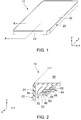
Fig. 1 is a perspective view of a device according to a first embodiment of the present invention. -
Fig. 2 is a cross-sectional view illustrating a part of the device ofFig. 1 , taken along line A--A. -
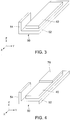
Fig. 3 is a perspective view illustrating a piezoelectric body plate and a first support part which are included in the device ofFig. 2 . -
Fig. 4 is a perspective view illustrating a modification of the piezoelectric body plate and the first support part ofFig. 2 . -
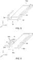
Fig. 5 is a perspective view illustrating another modification of the piezoelectric body plate and the first support part ofFig. 2 . -
Fig. 6 is a perspective view illustrating a piezoelectric body plate and a first support part which are included in a device according to a second embodiment of the present invention. -
Fig. 7 is a cross-sectional view illustrating a state where a secured part of the first support part ofFig. 6 is secured to a second support part, taken along line B--B. -
Fig. 8 is a perspective view illustrating a piezoelectric body plate and a first support part which are included in a device according to a third embodiment of the present invention. -
Fig. 9 is a cross-sectional view illustrating a state where a secured part of the first support part ofFig. 8 is secured to a second support part, taken along line C--C. -
Fig. 10 is a top view of a piezoelectric body plate and a first support part which are included in a device according a fourth embodiment of the present invention. -
Fig. 11 is a cross-sectional view illustrating a state where a secured part of the first support part ofFig. 10 is secured to a second support part, taken along line D--D. -
Fig. 12 is a perspective view of a piezoelectric body plate and a first support part which are included in a device according to a fifth embodiment of the present invention. -
Fig. 13 is a cross-sectional view illustrating a state where a secured part of the first support part ofFig. 12 is secured to a second support part, taken along line E--E. -
Fig. 14 is a top view of a piezoelectric body plate and a first support part which are included in a device according a sixth embodiment of the present invention. -
Fig. 15 is a cross-sectional view illustrating a state where a secured part of the first support part ofFig. 14 is secured to a second support part, taken along line F--F. -
Fig. 16 is a diagram illustrating frequency characteristics of sound pressures of sounds generated by devices according to embodiments of the present invention. - While the invention is susceptible to various modifications and alternative forms, specific embodiments thereof are shown by way of example in the drawings and will herein be described in detail. It should be understood, however, that the drawings and detailed description thereto are not intended to limit the invention to the particular form disclosed, but on the contrary, the intention is to cover all modifications, equivalents and alternatives falling within the spirit and scope of the present invention as defined by the appended claims.
- Referring to
Figs. 1 and 2 , adevice 10 according to a first embodiment of the present invention is provided with amain surface member 30 used as a vibrating plate, apiezoelectric body plate 40, afirst support part 50 supporting thepiezoelectric body plate 40 and ahousing 20. Thedevice 10 of the present embodiment is an electronic device such as a mobile phone, a tablet or a PC while themain surface member 30 is a glass plate constituting a screen of the electronic device, for example. In the present embodiment, themain surface member 30 is disposed to be parallel to a horizontal plane (an XY-plane). - As shown in
Figs. 1 and 2 , thehousing 20 has asecond support part 24 that supports themain surface member 30 and extends in a prescribed direction intersecting themain surface member 30. In the present embodiment, the prescribed direction is a vertical direction (or a Z-direction) perpendicular to themain surface member 30 while thesecond support part 24 is a side wall portion (or a part supporting themain surface member 30 formed of a glass plate) of thehousing 20 of the electronic device. Thus, thehousing 20 of the present embodiment is distinct and separated from themain surface member 30. - As illustrated in
Fig. 2 , on thepiezoelectric body plate 40, twoexternal electrodes external electrodes conductors piezoelectric body plate 40 vibrates according to the electric signal supplied. As understood fromFigs. 2 and3 , thepiezoelectric body plate 40 has a longitudinal direction in an X-direction and a short-direction in a Y-direction, in the present embodiment. Upon being supplied with the electric signal, thepiezoelectric body plate 40 vibrates so that both ends of thepiezoelectric body plate 40 in the longitudinal direction are moved in the vertical direction (the Z-direction). In other words, thepiezoelectric body plate 40 of the present embodiment carries out bending motion, which is a standing wave having a traveling direction in the longitudinal direction and a maximum amplitude at the both ends in the longitudinal direction, according to the electric signal. - As illustrated in
Figs. 2 and3 , thefirst support part 50 has a plate-likemain support part 52 supporting thepiezoelectric body plate 40 and asecured part 54 secured to thesecond support part 24. As with thepiezoelectric body plate 40, themain support part 52 has a longitudinal direction in the X-direction and a short-direction in the Y-direction. Thesecured part 54 is connected to themain support part 52 at a vicinity of one end of the longitudinal direction of themain support part 52. In detail, thesecured part 54 is situated at the vicinity of the one end of the longitudinal direction of themain support part 52 and extends in the vertical direction from one end of the short-direction of themain support part 52. Especially, thesecured part 54 is provided not to regulate vibration of themain support part 52 in the present embodiment. - The
first support part 50 of the present embodiment is made of fiber reinforced plastic. In more specifically, thefirst support part 50 is made of glass fiber reinforced polyamide resin. The present invention is not limited thereto. Thefirst support part 50 may be formed by bending a metal sheet, for example. Resin, however, is preferable for material of thefirst support part 50 since it is susceptible of a free shape in comparison with the metal sheet. It is desirable that a thickness (a size in the Z-direction) of themain support part 52 is equal to 0.2 mm or more and 2.0 mm or less from a viewpoint of transmission of the vibration of thepiezoelectric body plate 40. Moreover, it is desirable that thefirst support part 50 is made of an insulator having elastic modules, which is defined by ISO 178, of 7.6 GPa or more and 12.4 GPa or less in the viewpoint of the transmission of the vibration of thepiezoelectric body plate 40. - As illustrated in
Fig. 2 , thesecured part 54 of thefirst support part 50 is secured to thesecond support part 24. Specifically, thefirst support part 50 is glued or welded to thesecond support part 24. As a result of this securing, thesecond support part 24 vibrates in the vertical direction (the prescribed direction: the Z-direction) and the longitudinal direction (the X-direction) of thepiezoelectric body plate 40 according to the bending vibration of thepiezoelectric body plate 40. That is, thefirst support part 50 is secured to thesecond support part 24 so that thesecond support part 24 vibrates not only in the vertical direction but in a direction (the X-direction) parallel with themain surface member 30 according to the vibration of thepiezoelectric body plate 40. The vibration of thesecond support part 24 is transmitted to themain surface member 30, and themain surface member 30 vibrates to generate a sound. Thus, in the present embodiment, themain surface member 30 is made to vibrate by transmitting the vibration of thepiezoelectric body plate 40 to themain surface member 30 via thefirst support part 50 and thesecond support part 24 and thereby generating the sound. Especially, themain surface member 30 vibrates to be applied with torsion repeatedly since thesecond support part 24 of the present embodiment vibrates in the vertical direction and the longitudinal direction of thepiezoelectric body plate 40. As a result, a plurality of resonant points are generated, and the sound having good frequency characteristics can be generated. - In the present embodiment, the
first support part 50 supporting thepiezoelectric body plate 40 is directly secured to thesecond support part 24 of thehousing 20. A case for accommodating thepiezoelectric body plate 40 is not used in thehousing 20. Consequently, unlike the cases ofPatent Documents piezoelectric body plate 40. Moreover, a space necessary in thehousing 20 is small. That is, thedevice 10 of the present embodiment can obtain sufficient sound pressure even in a case where it is downsized and thinned. - Moreover, according to the present embodiment, since the
first support part 50 is secured to thesecond support part 24 in a state similar to a cantilever, a shock transmitted to thepiezoelectric body plate 40 can be reduced even in a case where the shock is added to thehousing 20 by falling or the like. - In the embodiment mentioned above, a
weight 70 secured to thepiezoelectric body plate 40 may be further provided as illustrated inFig. 4 or aweight 70a secured to thefirst support part 50 may be further provided as illustrated inFig. 5 . If theweight weight weights Figs. 4 and5 are one each, the number of theweight - A device according to a second embodiment of the present invention is a modification of the
device 10 according to the first embodiment illustrated inFigs. 1 and 2 and is provided with a similar configuration except for the configuration of the first support part and the securing structure against the second support part. Accordingly, the description will be made about the first support in detail in the following. - Referring to
Figs. 6 and7 , afirst support part 50b according to the present embodiment has amain support part 52b and asecured part 54b. As illustrated inFig. 6 , themain support part 52b has a plate-like shape and supports thepiezoelectric body plate 40. As with thepiezoelectric body plate 40, themain support part 52b has a longitudinal direction in the X-direction and a short-direction in the Y direction. Thesecured part 54b is connected to themain support part 52b at a vicinity of one end of the longitudinal direction of themain support part 52b. In detail, thesecured part 54b is situated at the vicinity of the one end of the longitudinal direction of themain support part 52b and extends in the vertical direction from one end of the short-direction of themain support part 52b. - As illustrated in
Figs. 6 and7 , a plurality of throughholes 56b are formed in thesecured part 54b. As illustrated inFig. 7 , thesecured part 54b is secured to thesecond support part 24 using an adhesive 58b.With this securing, in the same way as a case of the first embodiment mentioned above, the vibration of thepiezoelectric body plate 40 can be transmitted to the main surface member 30 (seeFig. 1 ). - Furthermore, in a case where the through
holes 56b are formed in thesecured part 54b as in the present embodiment, the adhesive 58b is filled in the throughholes 56b as illustrated inFig. 7 when thesecured part 54b is glued and secured to thesecond support part 24 using the adhesive 58b. Thus adhesion area between the adhesive 58b and thesecured part 54b can be enlarged, and securing strength of thesecured part 54b against thesecond support part 24 can be increased. To obtain similar effect, grooves reaching an upper end (a positive Z side end) of thesecured part 54b or grooves reaching a side end (a positive X side end or a negative X side end) of thesecured part 54b may be formed in place of the throughholes 56b. - A device according to a third embodiment of the present invention is a modification of the
device 10 according to the first embodiment illustrated inFigs. 1 and 2 and is provided with a similar configuration except for the configuration of the first support part and the securing structure of the second support part. Accordingly, the description will be made about the first support part in detail in the following. - Referring to
Figs. 8 and9 , afirst support part 50c according to the present embodiment has amain support part 52c and asecured part 54c. Themain support part 52c has a plate-like shape and supports thepiezoelectric body plate 40. As with thepiezoelectric body plate 40, themain support part 52c has a longitudinal direction in the X-direction and a short-direction in the Y-direction. Thesecured part 54c has a block shape and is connected to themain support part 52c at one end of the longitudinal direction of themain support part 52c. In detail, thesecured part 54c is situated at the one end of the longitudinal direction of themain support part 52c and is in a line with themain support part 52c in the longitudinal direction of themain support part 52c. - As illustrated in
Fig. 9 , thesecured part 54c is glued and secured to thesecond support part 24 in the longitudinal direction of themain support part 52c using adhesive 58c. Since thesecured part 54c is secured to thesecond support part 24 in this manner, thesecond support part 24 vibrates in the vertical direction (the prescribed direction) according to the vibration of thepiezoelectric body plate 40, and due to this the main surface member 30 (seeFig. 1 ) vibrates to allow to generate a sound. - A device according to a fourth embodiment of the present invention is a modification of the
device 10 according to the first embodiment illustrated inFigs. 1 and 2 and is provided with a similar configuration except for the configuration of the first support part and the securing structure against the second support part. Accordingly, the description will be made about the first support part in detail in the following. - Referring to
Figs. 10 and11 , afirst support part 50d according to the present embodiment has amain support part 52d and asecured part 54d. As illustrated inFig. 10 , themain support part 52d has a plate-like shape and supports thepiezoelectric body plate 40. As with thepiezoelectric body plate 40, themain support part 52d has a longitudinal direction in the X-direction and a short-direction in the Y-direction. Thesecured part 54d is connected to themain support part 52d at a vicinity of one end of the longitudinal direction of themain support part 52d. In detail, thesecured part 54d is situated in a vicinity of the one end of the longitudinal direction of themain support part 52d and extends on a plane (a X-Y plane) same as themain support part 52d from one end of the short-direction of themain support part 52d. - As illustrated in
Fig. 11 , thesecured part 54d is fit into and secured to thesecond support part 24. Securing means may be gluing or welding, for example. With this securing, in the same way as the case of the first embodiment mentioned above, the vibration of thepiezoelectric body plate 40 can be transmitted to the main surface member 30 (seeFig. 1 ). - A device according to a fifth embodiment of the present invention is a modification of the
device 10 according to the first embodiment illustrated inFigs. 1 and 2 and is provided with a similar configuration except for the configuration of the first support part and the securing structure against the second support part. Accordingly, the description will be made about the first support part in detail in the following. - Referring to
Figs. 12 and13 , afirst support part 50e according to the present embodiment has amain support part 52e and asecured part 54e. Themain support part 52e has a plate-like shape and supports thepiezoelectric body plate 40. As with thepiezoelectric body plate 40, themain support part 52e has a longitudinal direction in the X-direction and a short-direction in the Y-direction. Thesecured part 54e is connected to themain support part 52e at one end of the longitudinal direction of themain support part 52e. In detail, thesecured part 54e extends in the vertical direction (the prescribed direction) from the one end of the longitudinal direction of themain support part 52e. - As illustrated in
Fig. 13 , thesecured part 54e is glued and secured to thesecond support part 24 using an adhesive 58e in the longitudinal direction of themain support part 52c. Since thesecured part 54e is secured to thesecond support part 24 in this manner, thesecond support part 24 vibrates in the vertical direction (the prescribed direction) according to the vibration of thepiezoelectric body plate 40, and due to this the main surface member 30 (seeFig. 1 ) vibrates to allow to generate a sound. - A device according to a sixth embodiment of the present invention is a modification of the
device 10 according to the first embodiment illustrated inFigs. 1 and 2 and is provided with a similar configuration except for the configuration of the first support part and the securing structure against the second support part. Accordingly, the description will be made about the first support part in detail in the following. - Referring to
Figs. 14 and15 , afirst support part 50f according to the present embodiment has amain support part 52f and asecured part 54f. Themain support part 52f has a plate-like shape and supports thepiezoelectric body plate 40. As with thepiezoelectric body plate 40, themain support part 52f has a longitudinal direction in the X-direction and a short-direction in the Y-direction. Thesecured part 54f is connected to themain support part 52f at one end of the longitudinal direction of themain support part 52f. In detail, thesecured part 54f extends on a plane (the X-Y plane) same as themain support part 52f from the one end of the longitudinal direction of themain support part 52f. That is, themain support part 52f and thesecured part 54f are lined in the longitudinal direction (the X-direction) of the main support part 521. - As illustrated in
Fig. 15 , thesecured part 54f is fit into and secured to thesecond support part 24. Securing means may be gluing or welding, for example. With this securing, thesecond support part 24 vibrates in the vertical direction (the prescribed direction) according to the vibration of thepiezoelectric body plate 40, and due to this the main surface member 30 (seeFig. 1 ) vibrates to allow to generate a sound. - Although the specific explanation about the present invention is made above referring to the embodiments, the present invention is not limited thereto. Although the
first support part second support part 24, the present invention is not limited thereto. Thefirst support part second support part 24 and integrally molded. In such a case, thesecured part second support part 24. - Examples 1 and 2 provided with the structure (see
Figs. 1 to 3 ) of the first embodiment mentioned above have been manufactured. Afirst support part 50 of the first example is made of stainless steel and has amain support part 52 with 13.0 mm length, 4.5 mm width and 1.0 mm thickness and asecured part 54 with 6.0 mm width, 3.0 mm height and 1.0 mm thickness. Afirst support part 50 of the second example is made of glass-fiber-reinforced polyamide resin and has a size same as the example 1. -
Fig. 16 illustrates frequency characteristics of sound pressures of sounds generated in thedevices 10 which are provided with thefirst support parts 50 of the example 1 and the example 2. - Referring to
Fig. 16 , the sound generated by the example 1 has been able to obtain enough sound pressure even if a frequency is over 3.3 kHz which is the upper limit of audible area. Furthermore, the sound generated by the example 2 has exceeded the sound pressure of the example 1 when it has a frequency of about 1 kHz to 3 kHz. - The present invention is based on
Japanese Patent Applications Nos. 2013-223431 2014-161510 - While the best embodiments of the present invention have been described, as it is apparent to those skilled in the art, the embodiments are possible to be modified within a scope that is not departing from the spirit of the present invention, and such embodiments belong to the scope of the present invention.
-
- 10
- device
- 20
- housing
- 24
- second support part
- 30
- main surface member (glass plate: vibration plate)
- 40
- piezoelectric body plate
- 50, 50b, 50c, 50d, 50e, 50f
- first support part
- 52, 52b, 52c, 52d, 52e, 52f
- main support part
- 54, 54b, 54c, 54d, 54e, 54f
- secured part
- 56b
- through hole
- 58b, 58c, 58e
- adhesive
- 60, 62
- external electrode
- 64
- FPC
- 66, 68
- conductor
- 70, 70
- a →weight
Claims (11)
- A device comprising:a main surface member used as a vibration plate;a piezoelectric body plate that vibrates according to an electric signal;a first support part supporting the piezoelectric body plate; anda housing, whereinthe housing has a second support part supporting the main surface member and extending in a prescribed direction intersecting the main surface member,the first support part is secured to the second support so that the second support part vibrates in the prescribed direction according to vibration of the piezoelectric body plate, andthe vibration of the piezoelectric body plate is transmitted to the main surface member via the first support part and the second support part and thereby making the main surface member vibrate to generate a sound.
- The device recited in claim 1, wherein
the first support part is secured to the second support part so that the second support part vibrates in any direction parallel to the main surface member according to the vibration of the piezoelectric body plate. - The device recited in claim 1 or 2, wherein
the first support part has a plate-like main support part supporting the piezoelectric body plate and a secured part secured to the second support part,
the main support part has a longitudinal direction intersecting the prescribed direction,
the secured part is connected to the main support part at one end or a vicinity of the one end of the longitudinal direction of the main support part. - The device recited in claim 3, wherein
a thickness of the main support part is equal to 0.2 mm or more and 2.0 mm or less. - The device recited in any one of claims 1 to 4, wherein
the first support part is glued or welded to the second support part. - The device recited in any one of claims 1 to 4, wherein
the first support part is made of a material identical to the second support part and integrally molded. - The device recited in any one of claims 1 to 6, wherein
the first support part is made of insulator having elastic modules, which are defined by ISO 178, of 7.6 GPa or more and 12.4 GPa or less. - The device recited in any one of claims 1 to 7, wherein
the first support part is made of fiber reinforced plastic. - The device recited in claim 8, wherein
the fiber reinforced plastic is glass fiber reinforced polyamide resin. - The device recited in any one of claims 1 to 9, further comprising a weight provided on the piezoelectric body plate or the first support part.
- The device recited in any one of claims 1 to 10, wherein
the housing is distinct and separated from the main surface member.
Applications Claiming Priority (3)
| Application Number | Priority Date | Filing Date | Title |
|---|---|---|---|
| JP2013223431 | 2013-10-28 | ||
| JP2014161510A JP5676043B1 (en) | 2013-10-28 | 2014-08-07 | A device that generates sound |
| PCT/JP2014/077947 WO2015064421A1 (en) | 2013-10-28 | 2014-10-21 | Sound generator |
Publications (2)
| Publication Number | Publication Date |
|---|---|
| EP3051839A1 true EP3051839A1 (en) | 2016-08-03 |
| EP3051839A4 EP3051839A4 (en) | 2017-05-10 |
Family
ID=52672664
Family Applications (1)
| Application Number | Title | Priority Date | Filing Date |
|---|---|---|---|
| EP14857082.3A Withdrawn EP3051839A4 (en) | 2013-10-28 | 2014-10-21 | Sound generator |
Country Status (7)
| Country | Link |
|---|---|
| US (1) | US9743166B2 (en) |
| EP (1) | EP3051839A4 (en) |
| JP (1) | JP5676043B1 (en) |
| KR (1) | KR101539044B1 (en) |
| CN (1) | CN104756520B (en) |
| TW (1) | TWI571134B (en) |
| WO (1) | WO2015064421A1 (en) |
Cited By (1)
| Publication number | Priority date | Publication date | Assignee | Title |
|---|---|---|---|---|
| EP3904160A4 (en) * | 2018-12-28 | 2022-09-14 | Faurecia Clarion Electronics Co., Ltd. | VIBRATION GENERATING DEVICE |
Families Citing this family (9)
| Publication number | Priority date | Publication date | Assignee | Title |
|---|---|---|---|---|
| JP2018046487A (en) * | 2016-09-16 | 2018-03-22 | 株式会社トーキン | Sound vibration generator and electronic apparatus |
| US10356523B2 (en) * | 2017-12-13 | 2019-07-16 | Nvf Tech Ltd | Distributed mode loudspeaker actuator including patterned electrodes |
| US10681471B2 (en) | 2017-12-22 | 2020-06-09 | Google Llc | Two-dimensional distributed mode actuator |
| US10477321B2 (en) * | 2018-03-05 | 2019-11-12 | Google Llc | Driving distributed mode loudspeaker actuator that includes patterned electrodes |
| US10631072B2 (en) * | 2018-06-25 | 2020-04-21 | Google Llc | Actuator for distributed mode loudspeaker with extended damper and systems including the same |
| US10848875B2 (en) * | 2018-11-30 | 2020-11-24 | Google Llc | Reinforced actuators for distributed mode loudspeakers |
| US10462574B1 (en) | 2018-11-30 | 2019-10-29 | Google Llc | Reinforced actuators for distributed mode loudspeakers |
| TWI795085B (en) * | 2021-11-19 | 2023-03-01 | 達運精密工業股份有限公司 | Piezoelectric haptic structure |
| WO2025211342A1 (en) * | 2024-04-03 | 2025-10-09 | ローム株式会社 | Piezoelectric actuator, and method for manufacturing piezoelectric actuator |
Family Cites Families (20)
| Publication number | Priority date | Publication date | Assignee | Title |
|---|---|---|---|---|
| JPH1056498A (en) * | 1996-08-07 | 1998-02-24 | Sutatsufu Kk | Received call informing device for portable telephone set |
| JPH10285253A (en) * | 1997-03-31 | 1998-10-23 | Ceratec:Kk | Incoming call vibrating device and portable receiving device with the same |
| WO2002021881A1 (en) * | 2000-09-04 | 2002-03-14 | Applied Electronics Laboratories, Inc. | Display window having voice input/output function |
| JP3925414B2 (en) * | 2002-04-26 | 2007-06-06 | 株式会社村田製作所 | Piezoelectric electroacoustic transducer |
| WO2005104614A1 (en) * | 2004-04-22 | 2005-11-03 | 1...Limited | Loudspeaker |
| JP2007074062A (en) * | 2005-09-05 | 2007-03-22 | Citizen Electronics Co Ltd | Exciter for panel speaker and panel speaker |
| JP4511437B2 (en) | 2005-09-09 | 2010-07-28 | Necトーキン株式会社 | Piezoelectric device for generating acoustic signals |
| JP4688687B2 (en) | 2006-02-06 | 2011-05-25 | Necトーキン株式会社 | Piezoelectric vibration unit and panel speaker |
| JP2008251669A (en) | 2007-03-29 | 2008-10-16 | Kenwood Corp | Piezoelectric element |
| US8098855B2 (en) * | 2008-01-04 | 2012-01-17 | National Taiwan University | Flexible electret actuators and methods of manufacturing the same |
| CN101682819B (en) * | 2008-01-28 | 2013-10-30 | 日本先锋公司 | Speaker device |
| TW200952506A (en) * | 2008-06-05 | 2009-12-16 | Neovictory Technology Co Ltd | Piezoelectric actuator with positioning structure |
| TWM358493U (en) * | 2009-01-16 | 2009-06-01 | Jin-Ming Xiao | Slim type speaker |
| US9066183B2 (en) | 2010-04-15 | 2015-06-23 | Panasonic Intellectual Property Management Co., Ltd. | Piezoelectric speaker |
| JP2013030846A (en) * | 2011-07-26 | 2013-02-07 | Star Micronics Co Ltd | Piezoelectric exciter |
| WO2013099512A1 (en) * | 2011-12-26 | 2013-07-04 | 京セラ株式会社 | Vibration device, sound generator, speaker system, and electronic device |
| JP5901304B2 (en) * | 2012-01-20 | 2016-04-06 | 株式会社ファインウェル | Audio output device |
| JP5404970B1 (en) * | 2012-03-26 | 2014-02-05 | 京セラ株式会社 | Piezoelectric vibration component and portable terminal |
| US9571615B2 (en) * | 2012-03-29 | 2017-02-14 | Kyocera Corporation | Electronic apparatus, panel unit, and unit for electronic apparatus |
| KR101594827B1 (en) * | 2012-04-05 | 2016-02-17 | 엔이씨 도낀 가부시끼가이샤 | Piezoelectric element, piezoelectric vibration module, and manufacturing method of these |
-
2014
- 2014-08-07 JP JP2014161510A patent/JP5676043B1/en not_active Expired - Fee Related
- 2014-10-21 EP EP14857082.3A patent/EP3051839A4/en not_active Withdrawn
- 2014-10-21 US US15/031,150 patent/US9743166B2/en not_active Expired - Fee Related
- 2014-10-21 WO PCT/JP2014/077947 patent/WO2015064421A1/en not_active Ceased
- 2014-10-21 CN CN201480002910.1A patent/CN104756520B/en not_active Expired - Fee Related
- 2014-10-21 KR KR1020157011029A patent/KR101539044B1/en not_active Expired - Fee Related
- 2014-10-27 TW TW103137039A patent/TWI571134B/en not_active IP Right Cessation
Cited By (2)
| Publication number | Priority date | Publication date | Assignee | Title |
|---|---|---|---|---|
| EP3904160A4 (en) * | 2018-12-28 | 2022-09-14 | Faurecia Clarion Electronics Co., Ltd. | VIBRATION GENERATING DEVICE |
| US12185637B2 (en) | 2018-12-28 | 2024-12-31 | Faurecia Clarion Electronics Co., Ltd. | Vibration generation device |
Also Published As
| Publication number | Publication date |
|---|---|
| JP2015111810A (en) | 2015-06-18 |
| KR20150055086A (en) | 2015-05-20 |
| WO2015064421A1 (en) | 2015-05-07 |
| KR101539044B1 (en) | 2015-07-23 |
| US20160249120A1 (en) | 2016-08-25 |
| TWI571134B (en) | 2017-02-11 |
| CN104756520A (en) | 2015-07-01 |
| JP5676043B1 (en) | 2015-02-25 |
| US9743166B2 (en) | 2017-08-22 |
| CN104756520B (en) | 2016-05-25 |
| TW201528825A (en) | 2015-07-16 |
| EP3051839A4 (en) | 2017-05-10 |
Similar Documents
| Publication | Publication Date | Title |
|---|---|---|
| US9743166B2 (en) | Device generating sound | |
| KR101685962B1 (en) | Vibrator | |
| JP5496314B2 (en) | Haptic feedback device | |
| CN109511261A (en) | Vibration-damper structure, vibration device and tactile prompt device | |
| EP3223539A1 (en) | Sound generating device and electronic equipment | |
| KR101350543B1 (en) | Haptic feedback device and portable electronic equipment | |
| US8324786B2 (en) | Piezoelectric actuator module | |
| CN103116396A (en) | Haptic feedback device | |
| US9660172B2 (en) | Vibrator | |
| CN113556006B (en) | Vibration motor | |
| KR101316782B1 (en) | Vibrator mounted piezoelectric element | |
| CN207382557U (en) | Acoustic vibration generating means and electronic equipment | |
| JP6020465B2 (en) | Oscillator | |
| KR101640443B1 (en) | Vibrator | |
| KR20160069858A (en) | Vibrator and electronic device including the same | |
| US20250280244A1 (en) | Apparatus | |
| KR101660809B1 (en) | Vibrator | |
| KR101660824B1 (en) | Vibrator | |
| JP6884067B2 (en) | Piezoelectric sound module and OLED display device | |
| KR101652301B1 (en) | Vibrator |
Legal Events
| Date | Code | Title | Description |
|---|---|---|---|
| PUAI | Public reference made under article 153(3) epc to a published international application that has entered the european phase |
Free format text: ORIGINAL CODE: 0009012 |
|
| 17P | Request for examination filed |
Effective date: 20160426 |
|
| AK | Designated contracting states |
Kind code of ref document: A1 Designated state(s): AL AT BE BG CH CY CZ DE DK EE ES FI FR GB GR HR HU IE IS IT LI LT LU LV MC MK MT NL NO PL PT RO RS SE SI SK SM TR |
|
| AX | Request for extension of the european patent |
Extension state: BA ME |
|
| DAX | Request for extension of the european patent (deleted) | ||
| A4 | Supplementary search report drawn up and despatched |
Effective date: 20170410 |
|
| RIC1 | Information provided on ipc code assigned before grant |
Ipc: H04R 7/04 20060101AFI20170404BHEP Ipc: H04R 1/02 20060101ALI20170404BHEP Ipc: H04R 31/00 20060101ALI20170404BHEP Ipc: H04R 17/00 20060101ALI20170404BHEP |
|
| RAP1 | Party data changed (applicant data changed or rights of an application transferred) |
Owner name: SHARP KABUSHIKI KAISHA Owner name: TOKIN CORPORATION |
|
| 17Q | First examination report despatched |
Effective date: 20181206 |
|
| GRAP | Despatch of communication of intention to grant a patent |
Free format text: ORIGINAL CODE: EPIDOSNIGR1 |
|
| INTG | Intention to grant announced |
Effective date: 20200406 |
|
| STAA | Information on the status of an ep patent application or granted ep patent |
Free format text: STATUS: THE APPLICATION IS DEEMED TO BE WITHDRAWN |
|
| 18D | Application deemed to be withdrawn |
Effective date: 20200818 |