EP3051723A1 - Polarisation mode dispersion (pmd) tolerant optical signaling - Google Patents
Polarisation mode dispersion (pmd) tolerant optical signaling Download PDFInfo
- Publication number
- EP3051723A1 EP3051723A1 EP16153109.0A EP16153109A EP3051723A1 EP 3051723 A1 EP3051723 A1 EP 3051723A1 EP 16153109 A EP16153109 A EP 16153109A EP 3051723 A1 EP3051723 A1 EP 3051723A1
- Authority
- EP
- European Patent Office
- Prior art keywords
- polarization
- modulation
- eigenvectors
- sop
- optical signal
- Prior art date
- Legal status (The legal status is an assumption and is not a legal conclusion. Google has not performed a legal analysis and makes no representation as to the accuracy of the status listed.)
- Granted
Links
Images





Classifications
-
- H—ELECTRICITY
- H04—ELECTRIC COMMUNICATION TECHNIQUE
- H04B—TRANSMISSION
- H04B10/00—Transmission systems employing electromagnetic waves other than radio-waves, e.g. infrared, visible or ultraviolet light, or employing corpuscular radiation, e.g. quantum communication
- H04B10/60—Receivers
- H04B10/61—Coherent receivers
- H04B10/616—Details of the electronic signal processing in coherent optical receivers
- H04B10/6162—Compensation of polarization related effects, e.g., PMD, PDL
-
- H—ELECTRICITY
- H04—ELECTRIC COMMUNICATION TECHNIQUE
- H04B—TRANSMISSION
- H04B10/00—Transmission systems employing electromagnetic waves other than radio-waves, e.g. infrared, visible or ultraviolet light, or employing corpuscular radiation, e.g. quantum communication
- H04B10/25—Arrangements specific to fibre transmission
- H04B10/2507—Arrangements specific to fibre transmission for the reduction or elimination of distortion or dispersion
- H04B10/2569—Arrangements specific to fibre transmission for the reduction or elimination of distortion or dispersion due to polarisation mode dispersion [PMD]
-
- H—ELECTRICITY
- H04—ELECTRIC COMMUNICATION TECHNIQUE
- H04B—TRANSMISSION
- H04B10/00—Transmission systems employing electromagnetic waves other than radio-waves, e.g. infrared, visible or ultraviolet light, or employing corpuscular radiation, e.g. quantum communication
- H04B10/60—Receivers
- H04B10/61—Coherent receivers
- H04B10/616—Details of the electronic signal processing in coherent optical receivers
- H04B10/6166—Polarisation demultiplexing, tracking or alignment of orthogonal polarisation components
Definitions
- the present application relates generally to optical communications networks, and more specifically to polarization mode dispersion (PMD) tolerant optical signaling in an optical communications network.
- PMD polarization mode dispersion
- FIG. 1 illustrates a representative Wavelength Division Multiplexed (WDM) or Dense Wavelength Division Multiplexed (DWDM) optical system 2 known in the art.
- the system 2 comprises a set of transmitters 4 and a receivers 6 interconnected by an optical link 8, which in this illustration is taken to encompass the entire optical path between the transmitters 4 and the receivers 6.
- the link 8 includes optical fiber patch-cords 10 between each Tx 4 and a MUX 12 which operates to combine optical signals from each of the TXs 4 to generate a WDM or DWDM signal, which is then transmitted through a plurality of fiber spans 14 interconnected by discrete optical devices 16 to a receiver end of the link 8.
- a DEMUX 18 separates individual wavelength channels from the inbound WDM signal, and supplies each separated wavelength channel to a respective receiver 6 via an optical patch-cord 20.
- each optical component within the link 8 has at least some degree of birefringence. Consequently, the link 8 as a whole also exhibits a link birefringence that is the combined effect of the respective component birefringence of each optical component making up the optical link 8.
- the birefringence of some components can vary in time at rates of up to 20kHz or more. This time varying birefringence can be detected in a receiver 6 as a rapidly time varying Polarization Mode Dispersion (PMD).
- PMD Polarization Mode Dispersion
- a problem to be solved is how to implement a PMD tolerant optical communications system with reduced costs as compared to prior art techniques.
- An aspect of the present invention provides a PMD tolerant optical signalling method and system.
- aspects of the present invention provide a method of receiving an optical signal in a receiver of an optical communication system.
- the optical signal is transmitted by a transmitter of the optical communication system with a predetermined State of Polarization, SoP, in a succession of signalling intervals.
- SoP State of Polarization
- the SoP in each signalling interval is selected to excite two orthogonal eigenvectors of Polarization Mode Dispersion (PMD) of the optical communication system.
- PMD Polarization Mode Dispersion
- Modulation of the optical signal is detected in two orthogonal polarization directions.
- Data is recovered from modulation components associated with a selected one of the two orthogonal eigenvectors, based on the detected modulation of the received optical signal.
- a further aspect of the present invention provides a receiver of an optical communication system, the receiver comprises: a detector configured to detect modulation of a received optical signal in two orthogonal polarization directions, and a processor configured to recover data from modulation components of a selected one of the two orthogonal eigenvectors, based on the detected modulation of the received optical signal.
- the received optical signal having been transmitted by a transmitter of the optical communication system with a predetermined State of Polarization (SoP) in a succession of signalling intervals, wherein the SoP in each signalling interval exciting two orthogonal eigenvectors of Polarization Mode Dispersion (PMD) of the optical communication system.
- SoP State of Polarization
- PMD Polarization Mode Dispersion
- the SoP in a first signalling interval is different from the SoP in a second signalling interval.
- Detecting modulation of the received optical signal may comprise dividing, by a polarization beam splitter, the received optical signal into a pair of linearly polarized optical signals having a mutually orthogonal polarization orientations; detecting, by a photodetector block, respective modulation of each one of the linearly polarized optical signals; and generating, by an Analog-to Digital converter block, a respective polarization sample stream associated with each one of the linearly polarized optical signals, based on the modulation detected by the photodetector block.
- the predetermined State of Polarization may be polarized in each signalling interval.
- the signalling interval may correspond with a sample period of the transmitter.
- the signalling interval may correspond with a symbol period of the optical signal.
- a symbol period of the optical signal may correspond with a plurality of signalling intervals.
- recovering data from modulation components associated with the selected one of the two orthogonal eigenvectors may comprise: rotating the polarization sample streams to generate respective modulation sample streams of each eigenvector; and selecting the respective modulation sample stream of one of the eigenvectors based on a predetermined criterion.
- the predetermined criterion may comprise any one or more of a Bit Error Rate (BER) and a Signal to Noise Ratio (SNR).
- BER Bit Error Rate
- SNR Signal to Noise Ratio
- rotating the polarization sample streams may comprise: estimating an angle between the two orthogonal polarization directions and the eigenvectors; calculating at least one rotation vector based on the estimated angle; and applying the at least one rotation vector to each polarization sample stream to generate the modulation sample streams of each eigenvector.
- selecting modulation components associated with one of the two orthogonal eigenvectors may comprise discarding modulation components associated with the other one of the two orthogonal eigenvectors.
- data is recovered from one of the two eigenvectors of PMD of the optical communications system. Consequently, signal distortions due to modulation of the other eigenvector are avoided, which enables the data to be recovered even in the presence of significant PMD.
- a signalling interval may correspond with a modulated symbol (or baud) period.
- a signalling interval may correspond with a sample period of the transmitter.
- a signalling interval is a period of time in which the transmitter is capable of generating an optical signal with a desired State of Polarization (SoP).
- SoP State of Polarization
- Polarisation mode dispersion (PMD) to first order is a differential group delay (DGD) between two orthogonal polarisations. Due to the birefringence of the link 8, the DGD can be modeled as a pair of orthogonal Eigenvectors corresponding to the principal axes of the birefringence of the link, and respective Eigenvalues indicative of the magnitude of the DGD.
- the present technique provides a signalling system in which a signal is transmitted in a continuous series of signalling intervals.
- the signal transmitter operates such that, during each signalling interval the transmitted signal, the transmitted State of Polarization (SOP) of the signal is controlled to excite both Eigenvectors of the DGD.
- SOP State of Polarization
- the SOP of the signal averaged over a large number of signalling intervals, may be depolarized.
- the inbound signal is sampled and processed to compensate slow-changing impairments, such as chromatic dispersion.
- the resulting compensated sample stream is then processed to track the Eigenvectors of DGD. Samples most closely aligned with the Eigenvector yielding the best signal metrics are then selected for further processing to recover transmitted data. The remaining samples may be discarded.
- the signalling interval is a period of time in which the transmitter is configured to transmit an optical signal with a selected state of polarization.
- the signalling interval may correspond with a symbol (baud) period of the optical signal, which may span one or more sample periods.
- FIG. 2A schematically illustrates a transmitter 22 that is usable in the present technique.
- a transmitter 22 generally comprise an encoder 24, a driver 26, a Digital-to-Analog (D/A) converter 28 and a dual-polarization modulator 30.
- the encoder 24 is configured to encode a pair of digital data signals (Sx and Sy) using a suitable encoding scheme (such as, for example, Quadrature Phase Shift Keying , QPSK, or n-Quadrature Amplitude Modulation, n-QAM) to generate complex valued symbols d .
- a suitable encoding scheme such as, for example, Quadrature Phase Shift Keying , QPSK, or n-Quadrature Amplitude Modulation, n-QAM
- the driver circuit 26 then processes the symbols d to generate digital drive signals A that are designed to drive the modulator 38 to produce a desired e-field envelop of the modulated optical signal emitted at the output 32 of the transmitter 22.
- the digital drive signals A are converted into respective analog drive signals 6 by the Digital-to-Analog (D/A) converter 28 and modulated onto two dimensions (e.g. phase and amplitude, or In-phase (I) and Quadrature(Q)) of each of two orthogonal polarizations of a continuous wave (CW) optical carrier light.
- D/A Digital-to-Analog
- the CW carrier light is typically generated by a laser 34 in a manner known in the art, and the dual-polarization modulator 30 may be implemented using a polarization beam splitter 36 and any suitable modulator devices, such as phase modulators, variable optical attenuators, Mach-Zehnder interferometers, etc.
- the modulated optical signal appearing at the output 32 of the transmitter 22 may then be transmitted through the optical fiber link 8.
- the driver circuit 26 can operate to generate digital drive signals A designed to produce a modulated optical signal with any desired State of Polarization (SOP).
- the transmitter of FIG. 2A is capable of generating a polarization multiplexed optical signal comprising two linearly polarized signals having respective polarization axes oriented orthogonally to each other.
- the transmitter of FIG. 2A may be controlled to generate a polarization interleaved optical signal in which the optical signal comprises two linearly polarized signals having respective polarization axes oriented orthogonally to each other, and in which successive symbols are modulated onto each of the orthogonal linearly polarized signals in an alternating (or other) pattern.
- the transmitter may be controlled to generate a linearly polarized signal having its principal axis of polarization oriented at a desired angle.
- SoPs are also possible, as is known to those of ordinary skill in the art.
- FIG. 2B illustrates an alternative transmitter, which operates in a manner similar to the transmitter of FIG. 2A , except that the dual polarization modulator 30 ( FIG. 2A ) is replaced by a linear polarization modulator 38 comprising a modulation block 40 and a polarization rotator 42.
- the modulation block 40 may operate in a conventional manner to modulate the amplitude and/or phase of the CW carrier light from the laser 34, and the polarization rotator 42 is used to control an orientation of the principal axes of the modulated optical signal output from the modulation block 40.
- the driver circuit 26 may be configured to generate digital drive signals A that are designed to drive both the modulation block 40 and the polarization rotator 42.
- the 2B is configured to generate a polarized signal having its principal axis of polarization oriented at a desired angle.
- the orientation of the principal axis of polarization may be changed as desired, within the capabilities of the polarization rotator 42.
- the polarization rotator 42 can be controlled to change the orientation of the principal axis of polarization by ⁇ 90 degrees in a step-wise manner in every symbol (baud) interval, to yield a polarization multiplexed signal.
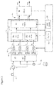
- FIG. 3 schematically illustrates principal elements and operations of a receiver 6 known, for example, from US patent No. 8,005,368, which issued on August 23, 2011 .
- an inbound optical signal is received through the optical link 8 (i.e. through patch-cord 20 from Demux 18), split into orthogonal received polarizations (denoted as X and Y) by a Polarization Beam Splitter 44, and then mixed with a Local Oscillator (LO) signal 46 by a conventional 90° optical hybrid 50.
- LO Local Oscillator
- the photodetector signals are sampled by respective Analog-to-Digital (A/D) converters 54 to yield raw multi-bit digital signals I X , Q X and I Y , Q Y corresponding to In-phase (I) and Quadrature (Q) components of each of the received X and Y polarizations.
- A/D Analog-to-Digital
- the raw multi-bit signals I X , Q X and I Y , Q Y are supplied to an equalizer 56 which includes respective dispersion compensators 58 for each of the X- and Y-polarization sample streams, and a polarization compensator 60.
- an equalizer 56 which includes respective dispersion compensators 58 for each of the X- and Y-polarization sample streams, and a polarization compensator 60.
- timing control methods described in Applicant's United States Patent No. 7,894,728, which issued to patent on February 22, 2011 including the use of elastic stores (not shown in FIG. 3 ) between the A/D converters 54 and the dispersion compensators 58 may be used to ensure at least coarse phase alignment between samples at the equalizer input.
- the dispersion compensators 58 operate to compensate chromatic dispersion impairments of the received optical signal.
- the dispersion-compensated digital signals 62 appearing at the output of the dispersion compensators 58 are then supplied to the polarization compensator 60 which operates to compensate polarization effects, and thereby de-convolve transmitted symbols from the complex signals 62 output from the dispersion compensators 58.
- the output of the polarization compensator 60 is a pair of multi-bit estimates 64 X'(n) and Y'(n) of the symbols encoded on each transmitted polarization of the optical signal by the transmitter.
- the symbol estimates 64 are then supplied to a carrier recovery block 66 for LO frequency control, symbol detection and data recovery, such as described in Applicant's United States Patent 7,606,498 issued October 20, 2009 .
- FIG. 4 schematically illustrates principal elements and operation of the equalizer 56 in greater detail.
- the dispersion compensator 58 and polarization compensator 60 are disposed within a pipelined series of functional blocks, including a deserializer 68, , a signal processor (FDP) 72 and a serializer block 74.
- FDP signal processor
- the deserializer 68 operates to accumulate successive n-bit words of the In-phase and Quadrature digital signals I X and Q X from the X-polarization A/D converters 54 IX and 54 QX , and I Y and Q Y from the Y-polarization A/D converters 54 IY and 54 QY during a predetermined clock period.
- the accumulated n-bit words are then latched into the signal processor 72 as a parallel input vector ⁇ r IX +jr QX ⁇ for the X polarization and ⁇ r IY +jr QY ⁇ for the Y polarization.
- the signal processor 72 may be configured to process the input vectors ⁇ r IX +jr QX ⁇ and ⁇ r IY +jr QY ⁇ in the frequency domain, in which case a suitable Fast Fourier Transform (FFT) block may be provided between the deserializer 68 and dispersion compensators 58 X and 58 Y .
- FFT Fast Fourier Transform
- the signal processor 72 can implement any of a variety of processing functions, as will be described in greater detail below, to yield modified arrays V X A and V Y A , which are supplied to respective serializer blocks 74.
- the serializer blocks 74 receive the modified arrays V X A and V Y A , and operate to generate the equalizer output 64 in the form of complex valued vectors ⁇ v IX +jv QX ⁇ and ⁇ v IY +jv QY ⁇ , each of which encompasses a plurality of complex valued symbol estimates X'(n) and Y'(n).
- the signal processor 72 may be configured to operate in the frequency domain.
- respective Inverse Fast Fourier Transform (IFFT) blocks may be provided between the polarization compensator 60 and each of the serializers 74, so as to generate time-domain output vectors ⁇ v IX +jv QX ⁇ and ⁇ v IY +jv QY ⁇ based on the frequency-domain modified arrays V X A and V Y A ,
- IFFT Inverse Fast Fourier Transform
- the signal processor 72 comprises the dispersion compensators 58 and the polarization compensator 60.
- the dispersion compensators 58 operates to multiply input arrays R X A and R Y A (e.g. from the deserializers 68 with a respective compensation vector ⁇ C X ⁇ and ⁇ C Y ⁇ , to yield intermediate arrays T X A and T Y A which are supplied to the polarization compensator 60.
- the compensation vectors ⁇ C X ⁇ and ⁇ C Y ⁇ can be computed, for example, using a Least Mean Squares (LMS) loop 84 based on residual errors in the intermediate arrays T X A and T Y A ,
- LMS Least Mean Squares
- the polarization compensator 60 is provided as a cross-compensation block which applies X-polarization vectors H XX , H XY to the X-polarization intermediate array ⁇ T A X ⁇ , and Y-polarization vectors H YY , H YX to the Y-polarization intermediate array ⁇ T A Y ⁇ .
- the multiplication results are then added together to generate the modified vectors ⁇ V A X ⁇ and ⁇ V A Y ⁇ , as may be seen in FIG. 4 .
- the X- and Y-polarization vectors H XX , H XY , H YY and H YX impose a phase rotation which compensates polarization impairments of the optical signal, and so de-convolve the transmitted symbols from the raw digital sample streams I X , Q X , and I Y , Q Y generated by the A/D converters 54.
- the illustrated cross-compensation block 60 implements an inverse-Jones matrix transfer function, which compensates the polarization effects.
- the vectors H XX , H XY , H YY and H YX are provided as the coefficients of the inverse-Jones matrix.
- the width of the inverse-Jones matrix is equal to that of the intermediate arrays ⁇ T A X ⁇ and ⁇ T A Y ⁇ , and so is based on the expected maximum dispersion of the received optical signal to be compensated by the equalizer 56.
- the X- and Y-polarization vectors H XX , H XY , H YY and H YX are preferably computed at sufficient speed to enable tracking, and thus compensation, of high-speed polarization rotation transients.
- this may be accomplished using a Least Mean Squares (LMS) update loop 86 illustrated in FIG. 4 .
- LMS Least Mean Squares
- LMS update loop 86 of the type described in US patent No. 8,005,368 may not be able to operate fast enough to fully compensate polarization impairments such as PMD. This may be particularly challenging as line (baud) rates exceed 400Gbaud/s. In other cases, a lower performance (i.e. baud rate) may be acceptable, but it is desired to avoid the cost and complexity associated with the LMS update loops as described in US patent No. 8,005,368 .
- the present technique is based on the recognition that when a polarized transmitted signal excites both eigenvectors of the link, the receiver will first detect the signal on the eigenvector corresponding to the principal axis of the link, and then a time-delayed version of the same signal on the other eigenvector.
- This is similar to multi-path interference known from radio-frequency (RF) communications, but differs from RF multi-path interference in that it is a function of birefringence in the optical link rather that multiple different propagation paths.
- RF radio-frequency
- a polarized optical signal having a State of Polarization (SoP) selected to excite both eigenvectors of the link At the receiver, the eigenvector having the best signal is detected and used for recovering received data.
- the other eigenvector, which contains a time delayed (or advanced) copy of the optical signal on the selected eigenvector, may be discarded.
- the total symbol (baud) rate of the communications system achieved in the present technique is reduced relative to the system of US patent No. 8,005,368 , for example, because data is modulated on only a single polarization during any given signaling interval.
- the present technique instead of tracking and compensating both the eigenvectors and eigenvalues of the PMD DGD, as in US patent No. 8,005,368 , the present technique only attempts to track the eigenvectors. This leads to a dramatic simplification of the polarization compensator 60 and LMS update loop 86 of the receiver shown in FIG. 4 . For example, FIG.
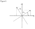
- the modulation power of the detected X- and Y-polarizations can be considered to be a sinusoidal projection of the modulation power of the link eigenvectors (corresponding to the principal axes 88 of the link birefringence).
- an estimate of the angle ⁇ may be found using the detected X- and Y-polarization modulation powers and simple trigonometric relationships.
- the SoP e.g. the orientation of the polarized light principle axis
- the transmitted signal becomes increasingly depolarised as the number of signalling intervals increases, and the angular error in the calculated value of ⁇ will tend to average to zero.
- the SoP may be changed in each successive signalling interval.
- the SoP may remain constant for a predetermined period of time (or, equivalently, number of signalling intervals) before changing.
- the SoP is changed such that the optical signal is substantially depolarized over a period of more than about two signalling intervals.
- the optical signal transmitted by the transmitter 22 may include periodic SYNC bursts having a known symbol sequence.
- the angle ⁇ may be calculated using only the periodic SYNC bursts, which may avoid errors due to erroneous symbol estimates X'(n), Y'(n) and corresponding decision values X (n), Y (n) for data symbols transmitted between the periodic SYNC bursts.
- the angle ⁇ can be used in combination with the modulation power(s) detected by the photodetectors 52 to estimate the respective modulation power of each eigenvector, again using simple trigonometric relationships, as illustrated in FIG. 5 .
- This operation may be conceived as a polarization rotation function, in which the orientation of the detected X- and Y polarizations is rotated to align with the eigenvectors of the link 8.
- periodic SYNC bursts within the received optical signal are used to calculate the angle of orientation ⁇ of the eigenvectors, relative to the detected X- and Y-polarization directions.
- the calculated angle ⁇ is then used to estimate the modulation power of each of the eigenvectors for subsequently received data symbols.
- the angle of orientation ⁇ of the eigenvectors can be updated at a rate equal to the frequency of the periodic SYNC bursts.
- the angle of orientation ⁇ of the eigenvectors are calculated using both the periodic SYNC bursts and data symbols modulated onto the optical signal between successive SYNC bursts. This arrangement enables the angle ⁇ to be updated much more rapidly than is possible when using the SYNC bursts alone, and any error in the angle ⁇ that accumulates while processing data symbols can be corrected upon processing the next SYNC burst.
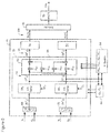
- FIG. 6 illustrates principal elements and operations of a signal equalizer 90 in accordance with a first representative embodiment of the present technique.
- the equalizer 90 follows the general architecture of the equalizer 56 of FIG. 4 , except that the polarization compensator 60 and LMS update loop 86 of FIG. 4 are replaced by a polarization rotator 92 and eigenvector updater 94, respectively.
- a selector 96 is inserted between the equalizer 90 and the carrier recovery block 66.
- the intermediate arrays ⁇ T A X ⁇ and ⁇ T A Y ⁇ output from the dispersion compensators 58 represent the modulation power of each of the detected X- and Y-polarization signals.
- the polarization rotator 92 operates to translate the intermediate arrays ⁇ T A X ⁇ and ⁇ T A Y ⁇ into modified arrays ⁇ M A X ⁇ and ⁇ M A Y ⁇ 98, which represent the corresponding modulation powers of the link eigenvectors 88 ( FIG. 5 ).
- the serializer blocks 74 operate in a manner largely described above, but in his case, the output 100 of the equalizer 90 comprises a pair of sample streams M X (n) and M Y (n) which represent the modulation power of each of the link eigenvectors 88.
- the selector 96 then operates to select one of the two sample streams M X (n) and M Y (n), and passes the selected sample stream to the carrier recovery block 66 for carrier recovery, LO control, and data detection in a known manner.
- the selector 96 may use any suitable criteria to select one of the two sample streams M X (n) and M Y (n). In some embodiments, the selection is based on a quality metric of the two signals. For example, a respective bit error rate (BER) or signal to noise ratio (SNR) of each of the two sample streams may be used to select a best one of the two streams. Other metrics may be used, as will be apparent to those of ordinary skill in the art. Typically, the selected sample stream will correspond with the principal axis of birefringence of the link.
- BER bit error rate
- SNR signal to noise ratio
- the selected sample streams is supplied to the carrier recovery block 66 for carrier recovery, LO control, and data detection in a conventional manner.
- the other (nonselected) sample stream will typically comprise a time-delayed or advanced version of the symbols encoded in the selected sample stream. Accordingly, the nonselected sample stream may be discarded, or used for any other purpose, as desired.
- the rotator 92 operates to rotate the polarization angle of the intermediate arrays ⁇ T A X ⁇ and ⁇ T A Y ⁇ to the link eigenvectors. This may be accomplished using a 2x2 Jones rotation similar to that implemented by the cross-compensation block 60 described above with reference to FIG. 4 , based on X- and Y-polarization vectors H XX , H XY , H YY and H YX calculated by the eigenvector updater 94.
- An important difference between the arrangement of FIG. 6 and that of FIG. 4 is that in the embodiment of FIG.
- the X- and Y-polarization vectors H XX , H XY , H YY and H YX have a width of only one tap. This represents a significant reduction of hardware complexity in both the rotator 92 and the eigenvector updater 94, relative to the cross-compensation block 60 and LMS update block 86 illustrated in FIG. 4 .
- FIG. 7 illustrates a representative embodiment of an eigenvector updater 94 usable for this purpose.
- the eigenvector updater 94 comprises a respective serializer block 102 for converting each of the intermediate arrays ⁇ T A X ⁇ and ⁇ T A Y ⁇ into time domain sample streams X"(n) and Y"(n) representing the dispersion-compensated modulation of each of the detected X- and Y-polarization signals.
- These signals are then provided to a polarization estimator 110, which operates as described above to calculate an estimate of the angle ⁇ between the detected X- and Y-polarization directions and the principal axes of birefringence of the link, which correspond with the link eigenvectors.
- a rotation calculator 112 then calculates the set of polarization coefficients for translating the detected polarization modulation powers into corresponding modulation power of the eigenvectors..
- the signal processor 72 may be configured to operate in the frequency domain.
- respective Inverse Fast Fourier Transform (IFFT) blocks may be provided between the each of the serializers 102 and the polarization estimator 110, so as to generate time-domain sample streams X"(n) and Y"(n) based on the frequency-domain intermediate arrays ⁇ T A X ⁇ and ⁇ T A Y ⁇ .
- IFFT Inverse Fast Fourier Transform
- Respective FTT blocks may also be used to convert the time domain polarization coefficients output from the rotation calculator 112 into corresponding frequency domain vectors H XX , H XY , H YY and H YX that can be supplied to the rotator 92 and applied to the intermediate arrays ⁇ T A X ⁇ and ⁇ T A Y ⁇ , in the frequency domain, to yield the modified arrays ⁇ M A X ⁇ and ⁇ M A Y ⁇ 98.
- An advantage of the embodiment of FIGs. 6 and 7 is that the modulation power of each of the detected X- and Y-polarization signals can be rotated to estimate the eigenvector excitation using polarization vectors H XX , H XY , H YY and H YX that have a width of as few as a single tap.
- the eigenvector updater 94 can use far fewer gates than is necessary for the LMS update loop 86 of FIG. 4 .
- the multipliers in each signal path need only be configured to process a respective polarization vector having a width of a single tap. This is because the rotator 92 does not attempt to compensate PMD (as does the polarization compensator 60 of FIG. 4 ) but rather avoids the effects of PMD by discarding modulation energy on one of the two principal axes of the link.
- each polarization vector H XX , H XY , H YY and H YX is a single tap, the rotation angle ⁇ can be calculated from much fewer samples that would otherwise be required. It is therefore possible to update the polarization vectors H XX , H XY , H YY and H YX at significantly higher rates than is possible using the LMS update loop 86 of FIG. 4 , which inherently requires the vectors H XX , H XY , H YY and H YX . to have a multiple-tap width in order to compensate PMD.
- a signalling interval may be taken as the shortest period in which the transmitter 22 is capable of transmitting a polarized optical signal with a desired State of Polarization (SoP).
- the signalling interval may correspond with a sample period of the D/A converters 28 in the transmitter 22.
- a signalling interval may correspond with a symbol period.
- the transmitter 22 may operate to transmit a given symbol in a symbol period that spans a plurality of signalling intervals, and using a different SoP in each interval.
- the selector 96 may be replaced by a phase selection block 116 that operates to select the best signalling interval to use for carrier recovery and data detection.
- FIG. 8 shows a representative phase selection block 116 that implements this operation.
- the transmitter 22 is assumed to modulate each symbol onto the optical carrier in a set of n consecutive timing intervals, using a respective different SoP in each of the n signal intervals.
- each of the two sample streams M X (n) and M Y (n) output by the equalizer 90 is formatted in the same manner, and so contains modulation associated with each transmitted symbol distributed over a set of n timing intervals.
- the phase selection block 116 operates to select the best combination of signalling interval and eigenvector, and passes the corresponding samples to the carrier recovery block 66.
- this operation can be considered to be analogous to a phase detection function, in which the optimal signal phase is selected that maximizes the receiver eye-opening.
- the phase selection block 116 of FIG. 8 comprises a respective distributer 118 that operates to distribute samples of each sample stream Mx(n) and M Y (n) across a respective set of n parallel paths.
- each path is associated with a respective one of the n timing intervals over which a given symbol is transmitted, and receives a set of one or more samples 100 output from the equalizer 90 in that time interval.
- a respective first-stage selector 120 then operates to select a best one of the n paths (signaling intervals), based on any suitable criteria (such as Bit Error Rate or Signal to Noise Ratio, for example), and passes the samples of that time interval to a second stage selector 122.
- the second stage selector 122 receives samples from the best signalling interval selected from each of the two eigenvectors. The second stage selector 122 then compares these samples (again using any suitable criteria) to select the best eignvector, and then passes the associated samples to the carrier recovery block 66.
- the arrangement of FIG. 8 is based on the implicit assumption that at least one of the n signalling intervals during which a given symbol is transmitted with a SoP that is close enough to the principal axes of the link birefringence to yield a satisfactory SNR in the receiver.
- the likelihood of this assumption being valid for a given symbol can be improved by selecting the SoP for each of the n signalling intervals such that the transmitted symbol is spread over at least a portion of the Poincare sphere.
- the second stage selector 122 performs an eigenvector selection function (similar to that of the selector 96 of FIG. 6 ), which means that the transmitted symbol only needs to be spread over half of the Poincare sphere. If the transmitted symbol is spread over the entire Poincare sphere, then the second stage selector 122 can be eliminated.
- phase selector 116 of FIG. 8 is described as being used in place of the selector 96 of FIG. 6 .
- the equalizer 90 including the polarization rotator 92 and angle update block 94, may be used in conjunction with the phase selector 116.
- the principal operation of the rotator 92 is to translate the modulation of the detected X- and Y-polarizations to the link principal axes of PMD.
- the transmitter is controlled to transmit an optical signal that is polarized in each signalling interval, with a SoP selected to excite both eigenvectors of the link PMD DGD.
- samples associated with one eigenvector are selected and used for data detection, whereas samples associated with the other eigenvector are a time delayed version of the samples associated with the selected eigenvector, and so may be are discarded.
- this arrangement has the benefit of avoiding differential group delay (DGD) due to Polarization Mode Dispersion (PMD), but at a cost of reduced spectral efficiency because the transmitter can only transmit a single polarized signal in any signalling interval. This means that a polarization interleaved signal may be used, but a polarization multiplexed signal cannot be used.
- This limitation may be overcome by retaining both sample streams 100 output from the equalizer 90 ( FIG. 6 ) and correcting the time delay, rather than discarding one of the sample streams.
- Timing control methods known, for example, from Applicant's United States Patent No. 7,894,728, which issued to patent on February 22, 2011 , including the use of elastic stores may be used to at least partially compensate the DGD and thereby ensure at least coarse phase alignment between the two sample streams M X (n) and M Y (n).
- the two sample streams M X (n) and M Y (n) may be retained, and processed using inverse Jones matrix methods to recover the transmitted symbols.
- An advantage of this arrangement is that it allows the transmitter to be driven to transmit a polarization multiplexed signal, which therefor has improved spectral efficiency relative the embodiment of FIGs. 6-8 .
Landscapes
- Physics & Mathematics (AREA)
- Electromagnetism (AREA)
- Engineering & Computer Science (AREA)
- Computer Networks & Wireless Communication (AREA)
- Signal Processing (AREA)
- Optical Communication System (AREA)
Abstract
Description
- The present application relates generally to optical communications networks, and more specifically to polarization mode dispersion (PMD) tolerant optical signaling in an optical communications network.
-
FIG. 1 illustrates a representative Wavelength Division Multiplexed (WDM) or Dense Wavelength Division Multiplexed (DWDM)optical system 2 known in the art. As may be seen inFIG. 1 , thesystem 2 comprises a set of transmitters 4 and areceivers 6 interconnected by anoptical link 8, which in this illustration is taken to encompass the entire optical path between the transmitters 4 and thereceivers 6. Thus thelink 8 includes optical fiber patch-cords 10 between each Tx 4 and aMUX 12 which operates to combine optical signals from each of the TXs 4 to generate a WDM or DWDM signal, which is then transmitted through a plurality offiber spans 14 interconnected by discreteoptical devices 16 to a receiver end of thelink 8. At the receiver end, aDEMUX 18 separates individual wavelength channels from the inbound WDM signal, and supplies each separated wavelength channel to arespective receiver 6 via an optical patch-cord 20. - Typically, each optical component within the
link 8 has at least some degree of birefringence. Consequently, thelink 8 as a whole also exhibits a link birefringence that is the combined effect of the respective component birefringence of each optical component making up theoptical link 8. As is known in the art, the birefringence of some components can vary in time at rates of up to 20kHz or more. This time varying birefringence can be detected in areceiver 6 as a rapidly time varying Polarization Mode Dispersion (PMD). - Methods are known for compensating PMD in a
receiver 6 by coherent detection of the channel signal and post-processing in a high speed Digital Signal Processor. However, in some cases, a lower cost solution would be desirable, even at a cost of somewhat reduced performance. - A problem to be solved, therefore, is how to implement a PMD tolerant optical communications system with reduced costs as compared to prior art techniques.
- The foregoing problem is solved by the combination of features defined in appended independent claims. Further, optional features are defined in the appended dependent claims.
- An aspect of the present invention provides a PMD tolerant optical signalling method and system.
- Thus aspects of the present invention provide a method of receiving an optical signal in a receiver of an optical communication system. The optical signal is transmitted by a transmitter of the optical communication system with a predetermined State of Polarization, SoP, in a succession of signalling intervals. The SoP in each signalling interval is selected to excite two orthogonal eigenvectors of Polarization Mode Dispersion (PMD) of the optical communication system. Modulation of the optical signal is detected in two orthogonal polarization directions. Data is recovered from modulation components associated with a selected one of the two orthogonal eigenvectors, based on the detected modulation of the received optical signal.
- A further aspect of the present invention provides a receiver of an optical communication system, the receiver comprises: a detector configured to detect modulation of a received optical signal in two orthogonal polarization directions, and a processor configured to recover data from modulation components of a selected one of the two orthogonal eigenvectors, based on the detected modulation of the received optical signal. The received optical signal having been transmitted by a transmitter of the optical communication system with a predetermined State of Polarization (SoP) in a succession of signalling intervals, wherein the SoP in each signalling interval exciting two orthogonal eigenvectors of Polarization Mode Dispersion (PMD) of the optical communication system.
- In some embodiments, the SoP in a first signalling interval is different from the SoP in a second signalling interval.
- Detecting modulation of the received optical signal may comprise dividing, by a polarization beam splitter, the received optical signal into a pair of linearly polarized optical signals having a mutually orthogonal polarization orientations; detecting, by a photodetector block, respective modulation of each one of the linearly polarized optical signals; and generating, by an Analog-to Digital converter block, a respective polarization sample stream associated with each one of the linearly polarized optical signals, based on the modulation detected by the photodetector block.
- Optionally, the predetermined State of Polarization (SoP) may be polarized in each signalling interval.
- Optionally, the signalling interval may correspond with a sample period of the transmitter. Alternatively, the signalling interval may correspond with a symbol period of the optical signal.
- Optionally, a symbol period of the optical signal may correspond with a plurality of signalling intervals.
- In some embodiments, recovering data from modulation components associated with the selected one of the two orthogonal eigenvectors may comprise: rotating the polarization sample streams to generate respective modulation sample streams of each eigenvector; and selecting the respective modulation sample stream of one of the eigenvectors based on a predetermined criterion.
- The predetermined criterion may comprise any one or more of a Bit Error Rate (BER) and a Signal to Noise Ratio (SNR).
- In some embodiments rotating the polarization sample streams may comprise: estimating an angle between the two orthogonal polarization directions and the eigenvectors; calculating at least one rotation vector based on the estimated angle; and applying the at least one rotation vector to each polarization sample stream to generate the modulation sample streams of each eigenvector.
- Optionally, selecting modulation components associated with one of the two orthogonal eigenvectors may comprise discarding modulation components associated with the other one of the two orthogonal eigenvectors.
- In accordance with the present invention, data is recovered from one of the two eigenvectors of PMD of the optical communications system. Consequently, signal distortions due to modulation of the other eigenvector are avoided, which enables the data to be recovered even in the presence of significant PMD.
- Further features and advantages of the present invention will become apparent from the following detailed description, taken in combination with the appended drawings, in which:
-
FIG. 1 is a block diagram schematically illustrating a representative optical communications system of a type in which the present invention may be used; -
FIGs. 2A and 2B are block diagrams schematically illustrating representative transmitters usable in the optical communications system ofFIG. 1 ; -
FIG. 3 is a block diagram schematically illustrating principal elements and operations of a coherent optical receiver that tracks both eigenvectors and eigenvalues of an inbound optical signal; -
FIG. 4 is a block diagram schematically illustrating principal elements and operations of the equalizer ofFIG. 3 in greater detail; -
FIG. 5 is a chart illustrating relationships between detected polarization directions and principal axes of birefringence in the optical communications system ofFIG. 1 ; -
FIG. 6 is a block diagram schematically illustrating principal elements and operations of an equalizer in accordance with a representative embodiment of the present technique; -
FIG. 7 is a block diagram schematically illustrating principal elements and operations of polarization angle update loop usable in the equalizer ofFIG. 6 ; and -
FIG. 8 is a block diagram schematically illustrating principal elements and operations of phase selector block in accordance with a second representative embodiment of the present technique. - It will be noted that throughout the appended drawings, like features are identified by like reference numerals.
- For the purposes of the present technique, it is useful to consider an optical signal as being decomposed into a continuous series of signalling intervals. In a simple conception, a signalling interval may correspond with a modulated symbol (or baud) period. In other embodiments, a signalling interval may correspond with a sample period of the transmitter. In general, a signalling interval is a period of time in which the transmitter is capable of generating an optical signal with a desired State of Polarization (SoP).
- Polarisation mode dispersion (PMD) to first order is a differential group delay (DGD) between two orthogonal polarisations. Due to the birefringence of the
link 8, the DGD can be modeled as a pair of orthogonal Eigenvectors corresponding to the principal axes of the birefringence of the link, and respective Eigenvalues indicative of the magnitude of the DGD. - In one aspect, the present technique provides a signalling system in which a signal is transmitted in a continuous series of signalling intervals. The signal transmitter operates such that, during each signalling interval the transmitted signal, the transmitted State of Polarization (SOP) of the signal is controlled to excite both Eigenvectors of the DGD. However, the SOP of the signal, averaged over a large number of signalling intervals, may be depolarized. At a receiver end of the link, the inbound signal is sampled and processed to compensate slow-changing impairments, such as chromatic dispersion. The resulting compensated sample stream is then processed to track the Eigenvectors of DGD. Samples most closely aligned with the Eigenvector yielding the best signal metrics are then selected for further processing to recover transmitted data. The remaining samples may be discarded.
- As noted above, in broad terms, the signalling interval is a period of time in which the transmitter is configured to transmit an optical signal with a selected state of polarization. For ease of construction, it may be convenient to select the signalling interval to correspond with the sample period of the transmitter (or, equivalently, a digital-to-analog converter of the transmitter), but this is not essential. For example, in some embodiments, the signalling interval may correspond with a symbol (baud) period of the optical signal, which may span one or more sample periods.
-
FIG. 2A schematically illustrates atransmitter 22 that is usable in the present technique. In the transmitter ofFIG. 2A , atransmitter 22 generally comprise anencoder 24, adriver 26, a Digital-to-Analog (D/A)converter 28 and a dual-polarization modulator 30. Theencoder 24 is configured to encode a pair of digital data signals (Sx and Sy) using a suitable encoding scheme (such as, for example, Quadrature Phase Shift Keying , QPSK, or n-Quadrature Amplitude Modulation, n-QAM) to generate complex valued symbolsd . Thedriver circuit 26 then processes the symbolsd to generate digital drive signalsA that are designed to drive themodulator 38 to produce a desired e-field envelop of the modulated optical signal emitted at theoutput 32 of thetransmitter 22. The digital drive signalsA are converted into respective analog drive signals 6 by the Digital-to-Analog (D/A)converter 28 and modulated onto two dimensions (e.g. phase and amplitude, or In-phase (I) and Quadrature(Q)) of each of two orthogonal polarizations of a continuous wave (CW) optical carrier light. The CW carrier light is typically generated by alaser 34 in a manner known in the art, and the dual-polarization modulator 30 may be implemented using apolarization beam splitter 36 and any suitable modulator devices, such as phase modulators, variable optical attenuators, Mach-Zehnder interferometers, etc. The modulated optical signal appearing at theoutput 32 of thetransmitter 22 may then be transmitted through theoptical fiber link 8. - With this arrangement, the
driver circuit 26 can operate to generate digital drive signalsA designed to produce a modulated optical signal with any desired State of Polarization (SOP). For example, the transmitter ofFIG. 2A is capable of generating a polarization multiplexed optical signal comprising two linearly polarized signals having respective polarization axes oriented orthogonally to each other. Alternatively, the transmitter ofFIG. 2A may be controlled to generate a polarization interleaved optical signal in which the optical signal comprises two linearly polarized signals having respective polarization axes oriented orthogonally to each other, and in which successive symbols are modulated onto each of the orthogonal linearly polarized signals in an alternating (or other) pattern. In a still further alternative, the transmitter may be controlled to generate a linearly polarized signal having its principal axis of polarization oriented at a desired angle. Other SoPs are also possible, as is known to those of ordinary skill in the art. -
FIG. 2B illustrates an alternative transmitter, which operates in a manner similar to the transmitter ofFIG. 2A , except that the dual polarization modulator 30 (FIG. 2A ) is replaced by alinear polarization modulator 38 comprising amodulation block 40 and apolarization rotator 42. Themodulation block 40 may operate in a conventional manner to modulate the amplitude and/or phase of the CW carrier light from thelaser 34, and thepolarization rotator 42 is used to control an orientation of the principal axes of the modulated optical signal output from themodulation block 40. In this case, thedriver circuit 26 may be configured to generate digital drive signalsA that are designed to drive both themodulation block 40 and thepolarization rotator 42. As may be appreciated, the transmitter ofFIG. 2B is configured to generate a polarized signal having its principal axis of polarization oriented at a desired angle. The orientation of the principal axis of polarization may be changed as desired, within the capabilities of thepolarization rotator 42. For example, thepolarization rotator 42 can be controlled to change the orientation of the principal axis of polarization by ±90 degrees in a step-wise manner in every symbol (baud) interval, to yield a polarization multiplexed signal. -
FIG. 3 schematically illustrates principal elements and operations of areceiver 6 known, for example, fromUS patent No. 8,005,368, which issued on August 23, 2011 . As may be seen inFIG. 3 , an inbound optical signal is received through the optical link 8 (i.e. through patch-cord 20 from Demux 18), split into orthogonal received polarizations (denoted as X and Y) by aPolarization Beam Splitter 44, and then mixed with a Local Oscillator (LO) signal 46 by a conventional 90°optical hybrid 50. The composite optical signals emerging from theoptical hybrid 50 are supplied torespective photodetectors 52, which generate corresponding analog electrical signals. The photodetector signals are sampled by respective Analog-to-Digital (A/D)converters 54 to yield raw multi-bit digital signals IX, QX and IY, QY corresponding to In-phase (I) and Quadrature (Q) components of each of the received X and Y polarizations. - From the A/
D converter block 54, the raw multi-bit signals IX, QX and IY, QY are supplied to anequalizer 56 which includes respective dispersion compensators 58 for each of the X- and Y-polarization sample streams, and apolarization compensator 60. If desired, timing control methods described in Applicant'sUnited States Patent No. 7,894,728, which issued to patent on February 22, 2011 , including the use of elastic stores (not shown inFIG. 3 ) between the A/D converters 54 and the dispersion compensators 58 may be used to ensure at least coarse phase alignment between samples at the equalizer input. In general, the dispersion compensators 58 operate to compensate chromatic dispersion impairments of the received optical signal. The dispersion-compensateddigital signals 62 appearing at the output of the dispersion compensators 58 are then supplied to thepolarization compensator 60 which operates to compensate polarization effects, and thereby de-convolve transmitted symbols from thecomplex signals 62 output from the dispersion compensators 58. The output of thepolarization compensator 60 is a pair of multi-bit estimates 64 X'(n) and Y'(n) of the symbols encoded on each transmitted polarization of the optical signal by the transmitter. The symbol estimates 64 are then supplied to acarrier recovery block 66 for LO frequency control, symbol detection and data recovery, such as described in Applicant'sUnited States Patent 7,606,498 issued October 20, 2009 . -
FIG. 4 schematically illustrates principal elements and operation of theequalizer 56 in greater detail. In the embodiment ofFIG. 4 , the dispersion compensator 58 andpolarization compensator 60 are disposed within a pipelined series of functional blocks, including adeserializer 68, , a signal processor (FDP) 72 and aserializer block 74. - The
deserializer 68 operates to accumulate successive n-bit words of the In-phase and Quadrature digital signals IX and QX from the X-polarization A/D converters D converters signal processor 72 as a parallel input vector {rIX+jrQX} for the X polarization and {rIY+jrQY} for the Y polarization. In some embodiments, thesignal processor 72 may be configured to process the input vectors {rIX+jrQX} and {rIY+jrQY} in the frequency domain, in which case a suitable Fast Fourier Transform (FFT) block may be provided between thedeserializer 68 and dispersion compensators 58X and 58Y. - The
signal processor 72 can implement any of a variety of processing functions, as will be described in greater detail below, to yield modified arrays

- The serializer blocks 74 receive the modified arrays


equalizer output 64 in the form of complex valued vectors {vIX+jvQX} and {vIY+jvQY}, each of which encompasses a plurality of complex valued symbol estimates X'(n) and Y'(n). In some embodiments, each of the vectors {vIX+jvQX} and {vIY+jvQY}, encompasses m=128 complex valued symbol estimates X'(n) and Y'(n). - As noted above, in some embodiments, the
signal processor 72 may be configured to operate in the frequency domain. In such cases, respective Inverse Fast Fourier Transform (IFFT) blocks may be provided between thepolarization compensator 60 and each of theserializers 74, so as to generate time-domain output vectors {vIX+jvQX} and {vIY+jvQY} based on the frequency-domain modified arrays

- In the embodiment of
FIG. 4 , thesignal processor 72 comprises the dispersion compensators 58 and thepolarization compensator 60. The dispersion compensators 58 operates to multiply input arrays

deserializers 68 with a respective compensation vector {CX } and {CY }, to yield intermediate arrays

polarization compensator 60. The compensation vectors {CX } and {CY } can be computed, for example, using a Least Mean Squares (LMS)loop 84 based on residual errors in the intermediate arrays

- As noted above, the
polarization compensator 60 is provided as a cross-compensation block which applies X-polarization vectors HXX, HXY to the X-polarization intermediate array {TA X}, and Y-polarization vectors HYY, HYX to the Y-polarization intermediate array {TA Y}. The multiplication results are then added together to generate the modified vectors {VA X} and {VA Y}, as may be seen inFIG. 4 . At a minimum, the X- and Y-polarization vectors HXX, HXY, HYY and HYX impose a phase rotation which compensates polarization impairments of the optical signal, and so de-convolve the transmitted symbols from the raw digital sample streams IX, QX, and IY, QY generated by the A/D converters 54. Those of ordinary skill in the art will recognise that the illustratedcross-compensation block 60 implements an inverse-Jones matrix transfer function, which compensates the polarization effects. In this formulation, the vectors HXX, HXY, HYY and HYX are provided as the coefficients of the inverse-Jones matrix. The width of the inverse-Jones matrix is equal to that of the intermediate arrays {TA X} and {TA Y}, and so is based on the expected maximum dispersion of the received optical signal to be compensated by theequalizer 56. - As may be appreciated, the X- and Y-polarization vectors HXX, HXY, HYY and HYX are preferably computed at sufficient speed to enable tracking, and thus compensation, of high-speed polarization rotation transients. In
US patent No. 8,005,368 , this may be accomplished using a Least Mean Squares (LMS)update loop 86 illustrated inFIG. 4 . - However, in some cases,
LMS update loop 86 of the type described inUS patent No. 8,005,368 may not be able to operate fast enough to fully compensate polarization impairments such as PMD. This may be particularly challenging as line (baud) rates exceed 400Gbaud/s. In other cases, a lower performance (i.e. baud rate) may be acceptable, but it is desired to avoid the cost and complexity associated with the LMS update loops as described inUS patent No. 8,005,368 . - The present technique is based on the recognition that when a polarized transmitted signal excites both eigenvectors of the link, the receiver will first detect the signal on the eigenvector corresponding to the principal axis of the link, and then a time-delayed version of the same signal on the other eigenvector. This is similar to multi-path interference known from radio-frequency (RF) communications, but differs from RF multi-path interference in that it is a function of birefringence in the optical link rather that multiple different propagation paths. In accordance with the present technique, this observation is exploited by controlling to transmitter 22 (
FIG. 2A and 2B ) to transmit a polarized optical signal having a State of Polarization (SoP) selected to excite both eigenvectors of the link. At the receiver, the eigenvector having the best signal is detected and used for recovering received data. The other eigenvector, which contains a time delayed (or advanced) copy of the optical signal on the selected eigenvector, may be discarded. - As may be appreciated, the total symbol (baud) rate of the communications system achieved in the present technique is reduced relative to the system of
US patent No. 8,005,368 , for example, because data is modulated on only a single polarization during any given signaling interval. However, instead of tracking and compensating both the eigenvectors and eigenvalues of the PMD DGD, as inUS patent No. 8,005,368 , the present technique only attempts to track the eigenvectors. This leads to a dramatic simplification of thepolarization compensator 60 andLMS update loop 86 of the receiver shown inFIG. 4 . For example,FIG. 5 illustrates the X- and Y-polarization directions separated by thepolarization beam splitter 44 and detected by thephotodetectors 52, and depicts the principal axes 88 of birefringence of the link 8 (corresponding with the eigenvectors) oriented at an angle θ with respect to the detected X- and Y-polarization directions. As may be seen inFIG. 5 , the modulation power of the detected X- and Y-polarizations can be considered to be a sinusoidal projection of the modulation power of the link eigenvectors (corresponding to the principal axes 88 of the link birefringence). For the case in which the transmitted signal is linearly polarized, an estimate of the angle θ may be found using the detected X- and Y-polarization modulation powers and simple trigonometric relationships. For example, inFIG. 5 , theangle 0 may be found as
- By changing the SoP (e.g. the orientation of the polarized light principle axis) of the transmitted signal at regular intervals, the transmitted signal becomes increasingly depolarised as the number of signalling intervals increases, and the angular error in the calculated value of θ will tend to average to zero. In some embodiments, the SoP may be changed in each successive signalling interval. In other embodiments, the SoP may remain constant for a predetermined period of time (or, equivalently, number of signalling intervals) before changing. In some embodiments, the SoP is changed such that the optical signal is substantially depolarized over a period of more than about two signalling intervals.
- In some embodiments, the optical signal transmitted by the
transmitter 22 may include periodic SYNC bursts having a known symbol sequence. In such cases, the angle θ may be calculated using only the periodic SYNC bursts, which may avoid errors due to erroneous symbol estimates X'(n), Y'(n) and corresponding decision values X (n), Y (n) for data symbols transmitted between the periodic SYNC bursts. - As may be appreciated, once the angle θ has been calculated, it can be used in combination with the modulation power(s) detected by the
photodetectors 52 to estimate the respective modulation power of each eigenvector, again using simple trigonometric relationships, as illustrated inFIG. 5 . For example, inFIG. 5 , the modulation power of the principal eigenvector may be found as MPE = MXcos -1(θ), where MPE is the modulation power of the principal eigenvector. This operation may be conceived as a polarization rotation function, in which the orientation of the detected X- and Y polarizations is rotated to align with the eigenvectors of thelink 8. - In some embodiments, periodic SYNC bursts within the received optical signal are used to calculate the angle of orientation θ of the eigenvectors, relative to the detected X- and Y-polarization directions. The calculated angle θ is then used to estimate the modulation power of each of the eigenvectors for subsequently received data symbols. With this arrangement, the angle of orientation θ of the eigenvectors can be updated at a rate equal to the frequency of the periodic SYNC bursts.
- In some embodiments, the angle of orientation θ of the eigenvectors are calculated using both the periodic SYNC bursts and data symbols modulated onto the optical signal between successive SYNC bursts. This arrangement enables the angle θ to be updated much more rapidly than is possible when using the SYNC bursts alone, and any error in the angle θ that accumulates while processing data symbols can be corrected upon processing the next SYNC burst.
-
FIG. 6 illustrates principal elements and operations of asignal equalizer 90 in accordance with a first representative embodiment of the present technique. Theequalizer 90 follows the general architecture of theequalizer 56 ofFIG. 4 , except that thepolarization compensator 60 andLMS update loop 86 ofFIG. 4 are replaced by apolarization rotator 92 andeigenvector updater 94, respectively. In addition, aselector 96 is inserted between theequalizer 90 and thecarrier recovery block 66. - Referring to
FIG. 6 , thedeserializers 68, and dispersion compensators 58 may operate in the same manner as described above with respect toFIG. 4 , and so will not be described again. The intermediate arrays {TA X} and {TA Y} output from the dispersion compensators 58 represent the modulation power of each of the detected X- and Y-polarization signals. Thepolarization rotator 92 operates to translate the intermediate arrays {TA X} and {TA Y} into modified arrays {MA X} and {MA Y} 98, which represent the corresponding modulation powers of the link eigenvectors 88 (FIG. 5 ). The serializer blocks 74 operate in a manner largely described above, but in his case, theoutput 100 of theequalizer 90 comprises a pair of sample streams MX(n) and MY(n) which represent the modulation power of each of the link eigenvectors 88. Theselector 96 then operates to select one of the two sample streams MX(n) and MY(n), and passes the selected sample stream to thecarrier recovery block 66 for carrier recovery, LO control, and data detection in a known manner. - The
selector 96 may use any suitable criteria to select one of the two sample streams MX(n) and MY(n). In some embodiments, the selection is based on a quality metric of the two signals. For example, a respective bit error rate (BER) or signal to noise ratio (SNR) of each of the two sample streams may be used to select a best one of the two streams. Other metrics may be used, as will be apparent to those of ordinary skill in the art. Typically, the selected sample stream will correspond with the principal axis of birefringence of the link. - As noted above, the selected sample streams is supplied to the
carrier recovery block 66 for carrier recovery, LO control, and data detection in a conventional manner. For the reduced case where thetransmitter 22 transmits a linearly polarized signal that excites both eigenvectors, the other (nonselected) sample stream will typically comprise a time-delayed or advanced version of the symbols encoded in the selected sample stream. Accordingly, the nonselected sample stream may be discarded, or used for any other purpose, as desired. - In the illustrated embodiment, the
rotator 92 operates to rotate the polarization angle of the intermediate arrays {TA X} and {TA Y} to the link eigenvectors. This may be accomplished using a 2x2 Jones rotation similar to that implemented by thecross-compensation block 60 described above with reference toFIG. 4 , based on X- and Y-polarization vectors HXX, HXY, HYY and HYX calculated by theeigenvector updater 94. An important difference between the arrangement ofFIG. 6 and that ofFIG. 4 , is that in the embodiment ofFIG. 6 , the X- and Y-polarization vectors HXX, HXY, HYY and HYX have a width of only one tap. This represents a significant reduction of hardware complexity in both therotator 92 and theeigenvector updater 94, relative to thecross-compensation block 60 andLMS update block 86 illustrated inFIG. 4 .FIG. 7 illustrates a representative embodiment of aneigenvector updater 94 usable for this purpose. - In the example of
FIG. 7 , theeigenvector updater 94 comprises arespective serializer block 102 for converting each of the intermediate arrays {TA X} and {TA Y} into time domain sample streams X"(n) and Y"(n) representing the dispersion-compensated modulation of each of the detected X- and Y-polarization signals. These signals are then provided to apolarization estimator 110, which operates as described above to calculate an estimate of the angle θ between the detected X- and Y-polarization directions and the principal axes of birefringence of the link, which correspond with the link eigenvectors. A rotation calculator 112 then calculates the set of polarization coefficients for translating the detected polarization modulation powers into corresponding modulation power of the eigenvectors.. - As noted above, in some embodiments, the
signal processor 72 may be configured to operate in the frequency domain. In such cases, respective Inverse Fast Fourier Transform (IFFT) blocks may be provided between the each of theserializers 102 and thepolarization estimator 110, so as to generate time-domain sample streams X"(n) and Y"(n) based on the frequency-domain intermediate arrays {TA X} and {TA Y}. Respective FTT blocks may also be used to convert the time domain polarization coefficients output from the rotation calculator 112 into corresponding frequency domain vectors HXX, HXY, HYY and HYX that can be supplied to therotator 92 and applied to the intermediate arrays {TA X} and {TA Y}, in the frequency domain, to yield the modified arrays {MA X} and {MA Y} 98. - An advantage of the embodiment of
FIGs. 6 and7 is that the modulation power of each of the detected X- and Y-polarization signals can be rotated to estimate the eigenvector excitation using polarization vectors HXX, HXY, HYY and HYX that have a width of as few as a single tap. This means that theeigenvector updater 94 can use far fewer gates than is necessary for theLMS update loop 86 ofFIG. 4 . For example, while therotator 92 still implements an inverse jones matrix function, the multipliers in each signal path need only be configured to process a respective polarization vector having a width of a single tap. This is because therotator 92 does not attempt to compensate PMD (as does thepolarization compensator 60 ofFIG. 4 ) but rather avoids the effects of PMD by discarding modulation energy on one of the two principal axes of the link. - Because the width of each polarization vector HXX, HXY, HYY and HYX is a single tap, the rotation angle θ can be calculated from much fewer samples that would otherwise be required. It is therefore possible to update the polarization vectors HXX, HXY, HYY and HYX at significantly higher rates than is possible using the
LMS update loop 86 ofFIG. 4 , which inherently requires the vectors HXX, HXY, HYY and HYX. to have a multiple-tap width in order to compensate PMD. - As noted above, a signalling interval may be taken as the shortest period in which the
transmitter 22 is capable of transmitting a polarized optical signal with a desired State of Polarization (SoP). In some embodiments, the signalling interval may correspond with a sample period of the D/A converters 28 in thetransmitter 22. In some embodiments, a signalling interval may correspond with a symbol period. However, other alternative arrangements are possible. For example, thetransmitter 22 may operate to transmit a given symbol in a symbol period that spans a plurality of signalling intervals, and using a different SoP in each interval. In this case, theselector 96 may be replaced by aphase selection block 116 that operates to select the best signalling interval to use for carrier recovery and data detection.FIG. 8 shows a representativephase selection block 116 that implements this operation. - For the illustrative example of
FIG. 8 , thetransmitter 22 is assumed to modulate each symbol onto the optical carrier in a set of n consecutive timing intervals, using a respective different SoP in each of the n signal intervals. In this arrangement, each of the two sample streams MX(n) and MY(n) output by theequalizer 90 is formatted in the same manner, and so contains modulation associated with each transmitted symbol distributed over a set of n timing intervals. Thephase selection block 116 operates to select the best combination of signalling interval and eigenvector, and passes the corresponding samples to thecarrier recovery block 66. Conceptually, this operation can be considered to be analogous to a phase detection function, in which the optimal signal phase is selected that maximizes the receiver eye-opening. - Accordingly, the
phase selection block 116 ofFIG. 8 comprises arespective distributer 118 that operates to distribute samples of each sample stream Mx(n) and MY(n) across a respective set of n parallel paths. In this case, each path is associated with a respective one of the n timing intervals over which a given symbol is transmitted, and receives a set of one ormore samples 100 output from theequalizer 90 in that time interval. A respective first-stage selector 120 then operates to select a best one of the n paths (signaling intervals), based on any suitable criteria (such as Bit Error Rate or Signal to Noise Ratio, for example), and passes the samples of that time interval to asecond stage selector 122. This results in thesecond stage selector 122 receiving samples from the best signalling interval selected from each of the two eigenvectors. Thesecond stage selector 122 then compares these samples (again using any suitable criteria) to select the best eignvector, and then passes the associated samples to thecarrier recovery block 66. - The arrangement of
FIG. 8 is based on the implicit assumption that at least one of the n signalling intervals during which a given symbol is transmitted with a SoP that is close enough to the principal axes of the link birefringence to yield a satisfactory SNR in the receiver. The likelihood of this assumption being valid for a given symbol can be improved by selecting the SoP for each of the n signalling intervals such that the transmitted symbol is spread over at least a portion of the Poincare sphere. In the embodiment ofFIG. 8 , thesecond stage selector 122 performs an eigenvector selection function (similar to that of theselector 96 ofFIG. 6 ), which means that the transmitted symbol only needs to be spread over half of the Poincare sphere. If the transmitted symbol is spread over the entire Poincare sphere, then thesecond stage selector 122 can be eliminated. - In the foregoing description, the
phase selector 116 ofFIG. 8 is described as being used in place of theselector 96 ofFIG. 6 . This implies that theequalizer 90, including thepolarization rotator 92 andangle update block 94, may be used in conjunction with thephase selector 116. However, the principal operation of therotator 92 is to translate the modulation of the detected X- and Y-polarizations to the link principal axes of PMD. In embodiments having a sufficiently large degree of oversampling (that is, each symbol is transmitted over a sufficiently large number n of signalling intervals), then it is likely that the transmitted SoP in at least one signalling interval is close enough to the principal axes of PMD that translation of the modulation from the detected X- and Y-polarizations to the link principal axes is not necessary. In such cases, thepolarization rotator 92 andupdate loop 94 can be omitted. - In the foregoing embodiments, the transmitter is controlled to transmit an optical signal that is polarized in each signalling interval, with a SoP selected to excite both eigenvectors of the link PMD DGD. In the receiver, samples associated with one eigenvector are selected and used for data detection, whereas samples associated with the other eigenvector are a time delayed version of the samples associated with the selected eigenvector, and so may be are discarded. As described above, this arrangement has the benefit of avoiding differential group delay (DGD) due to Polarization Mode Dispersion (PMD), but at a cost of reduced spectral efficiency because the transmitter can only transmit a single polarized signal in any signalling interval. This means that a polarization interleaved signal may be used, but a polarization multiplexed signal cannot be used.
- This limitation may be overcome by retaining both
sample streams 100 output from the equalizer 90 (FIG. 6 ) and correcting the time delay, rather than discarding one of the sample streams. Timing control methods known, for example, from Applicant'sUnited States Patent No. 7,894,728, which issued to patent on February 22, 2011 , including the use of elastic stores may be used to at least partially compensate the DGD and thereby ensure at least coarse phase alignment between the two sample streams MX(n) and MY(n). In this case, the two sample streams MX(n) and MY(n) may be retained, and processed using inverse Jones matrix methods to recover the transmitted symbols. An advantage of this arrangement is that it allows the transmitter to be driven to transmit a polarization multiplexed signal, which therefor has improved spectral efficiency relative the embodiment ofFIGs. 6-8 . - The embodiments of the invention described herein are intended to be illustrative only. The scope of the invention is therefore intended to be limited solely by the scope of the appended claims.
Claims (15)
- A method of receiving a signal in a receiver of an optical communication system, the method comprising:detecting modulation of a received optical signal in two orthogonal polarization directions, the optical signal having been transmitted by a transmitter of the optical communication system with a predetermined State of Polarization, SoP, in a succession of signalling intervals, the SoP in each signalling interval exciting two orthogonal eigenvectors of Polarization Mode Dispersion (PMD) of the optical communication system; andrecovering data from modulation components of a selected one of the two orthogonal eigenvectors, based on the detected modulation of the received optical signal.
- The method as claimed in claim 1, wherein the SoP in a first signalling interval is different from the SoP in a second signalling interval, and optionally, wherein the predetermined State of Polarization (SoP) is polarized in each signalling interval.
- The method as claimed in claim 1 or 2, wherein detecting modulation of the received optical signal comprises:dividing, by a polarization beam splitter (44), the received optical signal into a pair of linearly polarized optical signals having a mutually orthogonal polarization orientations;detecting, by a photodetector block (52), respective modulation of each one of the linearly polarized optical signals; andgenerating, by an Analog-to Digital converter block (54), a respective polarization sample stream associated with each one of the linearly polarized optical signals, based on the detected respective modulations.
- The method as claimed in claim 1, 2 or 3, wherein the signalling interval corresponds with either one of a sample period of the transmitter and a symbol period of the optical signal.
- The method as claimed in claim 3, wherein recovering data from modulation components associated with the selected one of the two orthogonal eigenvectors comprises:rotating the polarization sample streams to generate respective modulation sample streams of each eigenvector; andselecting the respective modulation sample stream of one of the eigenvectors based on a predetermined criterion.
- The method as claimed in claim 5, wherein the predetermined criterion comprises any one or more of a Bit Error Rate (BER) and a Signal to Noise Ratio (SNR).
- The method as claimed in claim 5, wherein rotating the polarization sample streams comprises:estimating an angle between the two orthogonal polarization directions and the eigenvectors;calculating at least one rotation vector based on the estimated angle; andapplying the at least one rotation vector to each polarization sample stream to generate the modulation sample streams of each eigenvector.
- The method as claimed in claim 1, wherein selecting modulation components associated with one of the two orthogonal eigenvectors comprises discarding modulation components associated with the other one of the two orthogonal eigenvectors.
- A receiver of an optical communication system, the receiver comprising:a detector (52) configured to detect modulation of a received optical signal in two orthogonal polarization directions, the optical signal having been transmitted by a transmitter of the optical communication system with a predetermined State of Polarization (SoP) in a succession of signalling intervals, wherein the SoP in each signalling interval exciting two orthogonal eigenvectors of Polarization Mode Dispersion (PMD) of the optical communication system; anda processor (72) configured to recover data from modulation components of a selected one of the two orthogonal eigenvectors, based on the detected modulation of the received optical signal;wherein the processor is optionally further configured to discard modulation components of the other one of the two orthogonal eigenvectors.
- The receiver as claimed in claim 9, wherein the SoP in a first signalling interval is different from the SoP in a second signalling interval, and optionally, wherein the predetermined State of Polarization (SoP) is polarized in each signalling interval.
- The receiver as claimed in claim 9, wherein the detector comprises:a polarization beam splitter (44) configured to divide the received optical signal into a pair of linearly polarized optical signals having a mutually orthogonal polarization orientations;a photodetector block (52) configured to detect respective modulation of each one of the linearly polarized optical signals; andan Analog-to Digital converter block (54) configured to generate a respective polarization sample stream associated with each one of the linearly polarized optical signals, based on the respective modulation detected by the photodetector block
- The receiver as claimed in claim 9, wherein the signalling interval corresponds with either one of a sample period of the transmitter and a symbol period of the optical signal.
- The receiver as claimed in claim 11, wherein the processor comprises:a polarization rotator (92) configured to rotate the polarization sample streams to generate respective modulation sample streams of each eigenvector; anda selector (96) configured to select the respective modulation sample stream of one of the eigenvectors based on a predetermined criterion.
- The receiver as claimed in claim 13, wherein the predetermined criterion comprises any one or more of a Bit Error Rate (BER) and a Signal to Noise Ratio (SNR).
- The receiver as claimed in claim 13, further comprising an update block configured to:estimate an angle between the two orthogonal polarization directions and the eigenvectors; andcalculate at least one rotation vector based on the estimated angle;wherein the polarization rotator is configured to apply the at least one rotation vector to each polarization sample stream to generate the modulation sample streams of each eigenvector.
Applications Claiming Priority (1)
| Application Number | Priority Date | Filing Date | Title |
|---|---|---|---|
| US14/607,276 US9520952B2 (en) | 2015-01-28 | 2015-01-28 | Polarization mode dispersion (PMD) tolerant optical signaling |
Publications (2)
| Publication Number | Publication Date |
|---|---|
| EP3051723A1 true EP3051723A1 (en) | 2016-08-03 |
| EP3051723B1 EP3051723B1 (en) | 2018-07-25 |
Family
ID=55521353
Family Applications (1)
| Application Number | Title | Priority Date | Filing Date |
|---|---|---|---|
| EP16153109.0A Active EP3051723B1 (en) | 2015-01-28 | 2016-01-28 | Polarisation mode dispersion (pmd) tolerant optical signaling |
Country Status (2)
| Country | Link |
|---|---|
| US (1) | US9520952B2 (en) |
| EP (1) | EP3051723B1 (en) |
Cited By (2)
| Publication number | Priority date | Publication date | Assignee | Title |
|---|---|---|---|---|
| EP4054093A1 (en) * | 2021-03-01 | 2022-09-07 | Google LLC | Polarization-folding coherent optical technology for short reach optical communication |
| US11641248B2 (en) | 2021-03-01 | 2023-05-02 | Google Llc | System, apparatus, and architecture for migrating an optical communication network |
Families Citing this family (4)
| Publication number | Priority date | Publication date | Assignee | Title |
|---|---|---|---|---|
| US10374752B2 (en) * | 2017-08-31 | 2019-08-06 | Inphi Corporation | Methods and systems for data transmission |
| US11011013B2 (en) | 2019-01-18 | 2021-05-18 | Robert McKee | System for identifying running streak wagering events and outcomes |
| US12119880B2 (en) * | 2020-08-10 | 2024-10-15 | Nokia Solutions And Networks Oy | Rapid polarization tracking in an optical channel |
| US11650340B2 (en) | 2020-12-01 | 2023-05-16 | Nokia Solutions And Networks Oy | Detection of seismic disturbances using optical fibers |
Citations (4)
| Publication number | Priority date | Publication date | Assignee | Title |
|---|---|---|---|---|
| US5473457A (en) * | 1993-12-20 | 1995-12-05 | Nec Corporation | Method and apparatus for compensating dispersion of polarization |
| US6646774B1 (en) * | 2001-03-16 | 2003-11-11 | Alan E. Willner | Intra-bit polarization diversity modulation |
| US7606498B1 (en) | 2005-10-21 | 2009-10-20 | Nortel Networks Limited | Carrier recovery in a coherent optical receiver |
| US8005368B2 (en) | 2007-12-05 | 2011-08-23 | Ciena Corporation | Signal equalizer in a coherent optical receiver |
Family Cites Families (7)
| Publication number | Priority date | Publication date | Assignee | Title |
|---|---|---|---|---|
| US7555227B2 (en) * | 2005-10-21 | 2009-06-30 | Nortel Networks Limited | Polarization compensation in a coherent optical receiver |
| US8135283B2 (en) * | 2009-04-07 | 2012-03-13 | Ciena Corporation | Clock recovery with channel coefficients |
| US8718491B2 (en) * | 2009-10-29 | 2014-05-06 | Ciena Corporation | Soft decoding of data in a coherent optical receiver |
| US8315528B2 (en) * | 2009-12-22 | 2012-11-20 | Ciena Corporation | Zero mean carrier recovery |
| US8306438B2 (en) * | 2010-04-12 | 2012-11-06 | Ciena Corporation | Coherent optical receiver systems and methods |
| US8929749B2 (en) * | 2011-10-05 | 2015-01-06 | Ciena Corporation | Minimum variance carrier recovery |
| US8983309B2 (en) * | 2012-02-13 | 2015-03-17 | Ciena Corporation | Constrained continuous phase modulation and demodulation in an optical communications system |
-
2015
- 2015-01-28 US US14/607,276 patent/US9520952B2/en active Active
-
2016
- 2016-01-28 EP EP16153109.0A patent/EP3051723B1/en active Active
Patent Citations (5)
| Publication number | Priority date | Publication date | Assignee | Title |
|---|---|---|---|---|
| US5473457A (en) * | 1993-12-20 | 1995-12-05 | Nec Corporation | Method and apparatus for compensating dispersion of polarization |
| US6646774B1 (en) * | 2001-03-16 | 2003-11-11 | Alan E. Willner | Intra-bit polarization diversity modulation |
| US7606498B1 (en) | 2005-10-21 | 2009-10-20 | Nortel Networks Limited | Carrier recovery in a coherent optical receiver |
| US7894728B1 (en) | 2005-10-21 | 2011-02-22 | Ciena Corporation | Sample timing control in an optical receiver |
| US8005368B2 (en) | 2007-12-05 | 2011-08-23 | Ciena Corporation | Signal equalizer in a coherent optical receiver |
Non-Patent Citations (1)
| Title |
|---|
| TUFT V L ET AL: "Time interleaved polarization multiplexing for polarization labelling", TRANSPARENT OPTICAL NETWORKS, 2005, PROCEEDINGS OF 2005 7TH INTERNATIO NAL CONFERENCE BARCELONA, CATLONIA, SPAIN JULY 3-7, 2005, PISCATAWAY, NJ, USA,IEEE, vol. 1, 3 July 2005 (2005-07-03), pages 47 - 51, XP010834263, ISBN: 978-0-7803-9236-6, DOI: 10.1109/ICTON.2005.1505750 * |
Cited By (5)
| Publication number | Priority date | Publication date | Assignee | Title |
|---|---|---|---|---|
| EP4054093A1 (en) * | 2021-03-01 | 2022-09-07 | Google LLC | Polarization-folding coherent optical technology for short reach optical communication |
| US11641248B2 (en) | 2021-03-01 | 2023-05-02 | Google Llc | System, apparatus, and architecture for migrating an optical communication network |
| US11689292B2 (en) | 2021-03-01 | 2023-06-27 | Google Llc | Polarization-folding coherent optical technology for short reach optical communication |
| US12255692B2 (en) | 2021-03-01 | 2025-03-18 | Google Llc | Polarization-folding coherent optical technology for short reach optical communication |
| US12323233B2 (en) | 2021-03-01 | 2025-06-03 | Google Llc | System, apparatus, and architecture for migrating an optical communication network |
Also Published As
| Publication number | Publication date |
|---|---|
| US9520952B2 (en) | 2016-12-13 |
| US20160218813A1 (en) | 2016-07-28 |
| EP3051723B1 (en) | 2018-07-25 |
Similar Documents
| Publication | Publication Date | Title |
|---|---|---|
| US7076169B2 (en) | System and method for orthogonal frequency division multiplexed optical communication | |
| US11469824B2 (en) | Apparatus and methods for digital signal constellation transformation | |
| US7167651B2 (en) | System and method for code division multiplexed optical communication | |
| EP3051723B1 (en) | Polarisation mode dispersion (pmd) tolerant optical signaling | |
| JP4755690B2 (en) | Optical field receiver and optical transmission system | |
| EP2097997B1 (en) | Adaptive polarization tracking and equalization in coherent optical receivers | |
| US10122489B2 (en) | Polarization state detector, optical transmitter, and optical receiver | |
| EP2420011B1 (en) | Method of and system for detecting skew between parallel signals | |
| US10608746B2 (en) | Mitigation of electrical-to-optical conversion impairments induced at transmitter | |
| US9729229B2 (en) | Optical spatial-division multiplexed transmission system and transmission method | |
| US9716564B2 (en) | Polarization tracking using signal tone information while keeping least mean squares frequency domain equalization | |
| EP2559173B1 (en) | Method and device for transmission and reception of a polarization multiplexed optical signal | |
| US8861960B2 (en) | Systems and methods for the compensation of nonlinear cross polarization and cross phase modulation in dual polarization coherent channels | |
| US9692521B1 (en) | Polarization pre-compensation technique for polarization-division-multiplexed direct-detection optical communication systems | |
| EP1329047A1 (en) | System and method for code division multiplexed optical communication | |
| WO2003028252A1 (en) | System and method for orthogonal frequency division multiplexed optical communication | |
| Sun et al. | Timing synchronization in coherent optical transmission systems | |
| US20250158712A1 (en) | Optical receive device and optical transmission system | |
| Gnauck et al. | Ultra-high-spectral-efficiency transmission |
Legal Events
| Date | Code | Title | Description |
|---|---|---|---|
| PUAI | Public reference made under article 153(3) epc to a published international application that has entered the european phase |
Free format text: ORIGINAL CODE: 0009012 |
|
| AK | Designated contracting states |
Kind code of ref document: A1 Designated state(s): AL AT BE BG CH CY CZ DE DK EE ES FI FR GB GR HR HU IE IS IT LI LT LU LV MC MK MT NL NO PL PT RO RS SE SI SK SM TR |
|
| AX | Request for extension of the european patent |
Extension state: BA ME |
|
| STAA | Information on the status of an ep patent application or granted ep patent |
Free format text: STATUS: REQUEST FOR EXAMINATION WAS MADE |
|
| 17P | Request for examination filed |
Effective date: 20161208 |
|
| RBV | Designated contracting states (corrected) |
Designated state(s): AL AT BE BG CH CY CZ DE DK EE ES FI FR GB GR HR HU IE IS IT LI LT LU LV MC MK MT NL NO PL PT RO RS SE SI SK SM TR |
|
| GRAP | Despatch of communication of intention to grant a patent |
Free format text: ORIGINAL CODE: EPIDOSNIGR1 |
|
| STAA | Information on the status of an ep patent application or granted ep patent |
Free format text: STATUS: GRANT OF PATENT IS INTENDED |
|
| INTG | Intention to grant announced |
Effective date: 20180201 |
|
| RAP1 | Party data changed (applicant data changed or rights of an application transferred) |
Owner name: CIENA CORPORATION |
|
| GRAS | Grant fee paid |
Free format text: ORIGINAL CODE: EPIDOSNIGR3 |
|
| GRAA | (expected) grant |
Free format text: ORIGINAL CODE: 0009210 |
|
| STAA | Information on the status of an ep patent application or granted ep patent |
Free format text: STATUS: THE PATENT HAS BEEN GRANTED |
|
| AK | Designated contracting states |
Kind code of ref document: B1 Designated state(s): AL AT BE BG CH CY CZ DE DK EE ES FI FR GB GR HR HU IE IS IT LI LT LU LV MC MK MT NL NO PL PT RO RS SE SI SK SM TR |
|
| REG | Reference to a national code |
Ref country code: GB Ref legal event code: FG4D |
|
| REG | Reference to a national code |
Ref country code: CH Ref legal event code: EP |
|
| REG | Reference to a national code |
Ref country code: AT Ref legal event code: REF Ref document number: 1022890 Country of ref document: AT Kind code of ref document: T Effective date: 20180815 |
|
| REG | Reference to a national code |
Ref country code: IE Ref legal event code: FG4D |
|
| REG | Reference to a national code |
Ref country code: DE Ref legal event code: R096 Ref document number: 602016004178 Country of ref document: DE |
|
| REG | Reference to a national code |
Ref country code: NL Ref legal event code: MP Effective date: 20180725 |
|
| REG | Reference to a national code |
Ref country code: LT Ref legal event code: MG4D |
|
| PG25 | Lapsed in a contracting state [announced via postgrant information from national office to epo] |
Ref country code: NL Free format text: LAPSE BECAUSE OF FAILURE TO SUBMIT A TRANSLATION OF THE DESCRIPTION OR TO PAY THE FEE WITHIN THE PRESCRIBED TIME-LIMIT Effective date: 20180725 |
|
| REG | Reference to a national code |
Ref country code: AT Ref legal event code: MK05 Ref document number: 1022890 Country of ref document: AT Kind code of ref document: T Effective date: 20180725 |
|
| PG25 | Lapsed in a contracting state [announced via postgrant information from national office to epo] |
Ref country code: NO Free format text: LAPSE BECAUSE OF FAILURE TO SUBMIT A TRANSLATION OF THE DESCRIPTION OR TO PAY THE FEE WITHIN THE PRESCRIBED TIME-LIMIT Effective date: 20181025 Ref country code: GR Free format text: LAPSE BECAUSE OF FAILURE TO SUBMIT A TRANSLATION OF THE DESCRIPTION OR TO PAY THE FEE WITHIN THE PRESCRIBED TIME-LIMIT Effective date: 20181026 Ref country code: SE Free format text: LAPSE BECAUSE OF FAILURE TO SUBMIT A TRANSLATION OF THE DESCRIPTION OR TO PAY THE FEE WITHIN THE PRESCRIBED TIME-LIMIT Effective date: 20180725 Ref country code: PL Free format text: LAPSE BECAUSE OF FAILURE TO SUBMIT A TRANSLATION OF THE DESCRIPTION OR TO PAY THE FEE WITHIN THE PRESCRIBED TIME-LIMIT Effective date: 20180725 Ref country code: RS Free format text: LAPSE BECAUSE OF FAILURE TO SUBMIT A TRANSLATION OF THE DESCRIPTION OR TO PAY THE FEE WITHIN THE PRESCRIBED TIME-LIMIT Effective date: 20180725 Ref country code: FI Free format text: LAPSE BECAUSE OF FAILURE TO SUBMIT A TRANSLATION OF THE DESCRIPTION OR TO PAY THE FEE WITHIN THE PRESCRIBED TIME-LIMIT Effective date: 20180725 Ref country code: LT Free format text: LAPSE BECAUSE OF FAILURE TO SUBMIT A TRANSLATION OF THE DESCRIPTION OR TO PAY THE FEE WITHIN THE PRESCRIBED TIME-LIMIT Effective date: 20180725 Ref country code: AT Free format text: LAPSE BECAUSE OF FAILURE TO SUBMIT A TRANSLATION OF THE DESCRIPTION OR TO PAY THE FEE WITHIN THE PRESCRIBED TIME-LIMIT Effective date: 20180725 Ref country code: IS Free format text: LAPSE BECAUSE OF FAILURE TO SUBMIT A TRANSLATION OF THE DESCRIPTION OR TO PAY THE FEE WITHIN THE PRESCRIBED TIME-LIMIT Effective date: 20181125 Ref country code: BG Free format text: LAPSE BECAUSE OF FAILURE TO SUBMIT A TRANSLATION OF THE DESCRIPTION OR TO PAY THE FEE WITHIN THE PRESCRIBED TIME-LIMIT Effective date: 20181025 |
|
| PG25 | Lapsed in a contracting state [announced via postgrant information from national office to epo] |
Ref country code: AL Free format text: LAPSE BECAUSE OF FAILURE TO SUBMIT A TRANSLATION OF THE DESCRIPTION OR TO PAY THE FEE WITHIN THE PRESCRIBED TIME-LIMIT Effective date: 20180725 Ref country code: LV Free format text: LAPSE BECAUSE OF FAILURE TO SUBMIT A TRANSLATION OF THE DESCRIPTION OR TO PAY THE FEE WITHIN THE PRESCRIBED TIME-LIMIT Effective date: 20180725 Ref country code: HR Free format text: LAPSE BECAUSE OF FAILURE TO SUBMIT A TRANSLATION OF THE DESCRIPTION OR TO PAY THE FEE WITHIN THE PRESCRIBED TIME-LIMIT Effective date: 20180725 |
|
| REG | Reference to a national code |
Ref country code: DE Ref legal event code: R097 Ref document number: 602016004178 Country of ref document: DE |
|
| PG25 | Lapsed in a contracting state [announced via postgrant information from national office to epo] |
Ref country code: EE Free format text: LAPSE BECAUSE OF FAILURE TO SUBMIT A TRANSLATION OF THE DESCRIPTION OR TO PAY THE FEE WITHIN THE PRESCRIBED TIME-LIMIT Effective date: 20180725 Ref country code: RO Free format text: LAPSE BECAUSE OF FAILURE TO SUBMIT A TRANSLATION OF THE DESCRIPTION OR TO PAY THE FEE WITHIN THE PRESCRIBED TIME-LIMIT Effective date: 20180725 Ref country code: IT Free format text: LAPSE BECAUSE OF FAILURE TO SUBMIT A TRANSLATION OF THE DESCRIPTION OR TO PAY THE FEE WITHIN THE PRESCRIBED TIME-LIMIT Effective date: 20180725 Ref country code: CZ Free format text: LAPSE BECAUSE OF FAILURE TO SUBMIT A TRANSLATION OF THE DESCRIPTION OR TO PAY THE FEE WITHIN THE PRESCRIBED TIME-LIMIT Effective date: 20180725 Ref country code: ES Free format text: LAPSE BECAUSE OF FAILURE TO SUBMIT A TRANSLATION OF THE DESCRIPTION OR TO PAY THE FEE WITHIN THE PRESCRIBED TIME-LIMIT Effective date: 20180725 |
|
| PG25 | Lapsed in a contracting state [announced via postgrant information from national office to epo] |
Ref country code: SK Free format text: LAPSE BECAUSE OF FAILURE TO SUBMIT A TRANSLATION OF THE DESCRIPTION OR TO PAY THE FEE WITHIN THE PRESCRIBED TIME-LIMIT Effective date: 20180725 Ref country code: DK Free format text: LAPSE BECAUSE OF FAILURE TO SUBMIT A TRANSLATION OF THE DESCRIPTION OR TO PAY THE FEE WITHIN THE PRESCRIBED TIME-LIMIT Effective date: 20180725 Ref country code: SM Free format text: LAPSE BECAUSE OF FAILURE TO SUBMIT A TRANSLATION OF THE DESCRIPTION OR TO PAY THE FEE WITHIN THE PRESCRIBED TIME-LIMIT Effective date: 20180725 |
|
| PLBE | No opposition filed within time limit |
Free format text: ORIGINAL CODE: 0009261 |
|
| STAA | Information on the status of an ep patent application or granted ep patent |
Free format text: STATUS: NO OPPOSITION FILED WITHIN TIME LIMIT |
|
| 26N | No opposition filed |
Effective date: 20190426 |
|
| PG25 | Lapsed in a contracting state [announced via postgrant information from national office to epo] |
Ref country code: MC Free format text: LAPSE BECAUSE OF FAILURE TO SUBMIT A TRANSLATION OF THE DESCRIPTION OR TO PAY THE FEE WITHIN THE PRESCRIBED TIME-LIMIT Effective date: 20180725 Ref country code: SI Free format text: LAPSE BECAUSE OF FAILURE TO SUBMIT A TRANSLATION OF THE DESCRIPTION OR TO PAY THE FEE WITHIN THE PRESCRIBED TIME-LIMIT Effective date: 20180725 |
|
| REG | Reference to a national code |
Ref country code: CH Ref legal event code: PL |
|
| PG25 | Lapsed in a contracting state [announced via postgrant information from national office to epo] |
Ref country code: LU Free format text: LAPSE BECAUSE OF NON-PAYMENT OF DUE FEES Effective date: 20190128 |
|
| REG | Reference to a national code |
Ref country code: BE Ref legal event code: MM Effective date: 20190131 |
|
| REG | Reference to a national code |
Ref country code: IE Ref legal event code: MM4A |
|
| PG25 | Lapsed in a contracting state [announced via postgrant information from national office to epo] |
Ref country code: BE Free format text: LAPSE BECAUSE OF NON-PAYMENT OF DUE FEES Effective date: 20190131 |
|
| PG25 | Lapsed in a contracting state [announced via postgrant information from national office to epo] |
Ref country code: CH Free format text: LAPSE BECAUSE OF NON-PAYMENT OF DUE FEES Effective date: 20190131 Ref country code: LI Free format text: LAPSE BECAUSE OF NON-PAYMENT OF DUE FEES Effective date: 20190131 |
|
| PG25 | Lapsed in a contracting state [announced via postgrant information from national office to epo] |
Ref country code: IE Free format text: LAPSE BECAUSE OF NON-PAYMENT OF DUE FEES Effective date: 20190128 |
|
| PG25 | Lapsed in a contracting state [announced via postgrant information from national office to epo] |
Ref country code: TR Free format text: LAPSE BECAUSE OF FAILURE TO SUBMIT A TRANSLATION OF THE DESCRIPTION OR TO PAY THE FEE WITHIN THE PRESCRIBED TIME-LIMIT Effective date: 20180725 |
|
| PG25 | Lapsed in a contracting state [announced via postgrant information from national office to epo] |
Ref country code: MT Free format text: LAPSE BECAUSE OF NON-PAYMENT OF DUE FEES Effective date: 20190128 Ref country code: PT Free format text: LAPSE BECAUSE OF FAILURE TO SUBMIT A TRANSLATION OF THE DESCRIPTION OR TO PAY THE FEE WITHIN THE PRESCRIBED TIME-LIMIT Effective date: 20181125 |
|
| PG25 | Lapsed in a contracting state [announced via postgrant information from national office to epo] |
Ref country code: CY Free format text: LAPSE BECAUSE OF FAILURE TO SUBMIT A TRANSLATION OF THE DESCRIPTION OR TO PAY THE FEE WITHIN THE PRESCRIBED TIME-LIMIT Effective date: 20180725 |
|
| PG25 | Lapsed in a contracting state [announced via postgrant information from national office to epo] |
Ref country code: HU Free format text: LAPSE BECAUSE OF FAILURE TO SUBMIT A TRANSLATION OF THE DESCRIPTION OR TO PAY THE FEE WITHIN THE PRESCRIBED TIME-LIMIT; INVALID AB INITIO Effective date: 20160128 |
|
| PG25 | Lapsed in a contracting state [announced via postgrant information from national office to epo] |
Ref country code: MK Free format text: LAPSE BECAUSE OF FAILURE TO SUBMIT A TRANSLATION OF THE DESCRIPTION OR TO PAY THE FEE WITHIN THE PRESCRIBED TIME-LIMIT Effective date: 20180725 |
|
| P01 | Opt-out of the competence of the unified patent court (upc) registered |
Effective date: 20230515 |
|
| PGFP | Annual fee paid to national office [announced via postgrant information from national office to epo] |
Ref country code: GB Payment date: 20260123 Year of fee payment: 11 |
|
| PGFP | Annual fee paid to national office [announced via postgrant information from national office to epo] |
Ref country code: DE Payment date: 20260121 Year of fee payment: 11 |
|
| PGFP | Annual fee paid to national office [announced via postgrant information from national office to epo] |
Ref country code: FR Payment date: 20260123 Year of fee payment: 11 |