EP3051562B1 - Spring Member for an Electric Switching Device such as a Cradle Relay - Google Patents
Spring Member for an Electric Switching Device such as a Cradle Relay Download PDFInfo
- Publication number
- EP3051562B1 EP3051562B1 EP15153202.5A EP15153202A EP3051562B1 EP 3051562 B1 EP3051562 B1 EP 3051562B1 EP 15153202 A EP15153202 A EP 15153202A EP 3051562 B1 EP3051562 B1 EP 3051562B1
- Authority
- EP
- European Patent Office
- Prior art keywords
- section
- switching device
- spring
- electric switching
- spring section
- Prior art date
- Legal status (The legal status is an assumption and is not a legal conclusion. Google has not performed a legal analysis and makes no representation as to the accuracy of the status listed.)
- Active
Links
Images



Classifications
-
- H—ELECTRICITY
- H01—ELECTRIC ELEMENTS
- H01H—ELECTRIC SWITCHES; RELAYS; SELECTORS; EMERGENCY PROTECTIVE DEVICES
- H01H50/00—Details of electromagnetic relays
- H01H50/54—Contact arrangements
- H01H50/56—Contact spring sets
- H01H50/58—Driving arrangements structurally associated therewith; Mounting of driving arrangements on armature
-
- H—ELECTRICITY
- H01—ELECTRIC ELEMENTS
- H01H—ELECTRIC SWITCHES; RELAYS; SELECTORS; EMERGENCY PROTECTIVE DEVICES
- H01H50/00—Details of electromagnetic relays
- H01H50/54—Contact arrangements
- H01H50/56—Contact spring sets
-
- H—ELECTRICITY
- H01—ELECTRIC ELEMENTS
- H01H—ELECTRIC SWITCHES; RELAYS; SELECTORS; EMERGENCY PROTECTIVE DEVICES
- H01H50/00—Details of electromagnetic relays
- H01H50/64—Driving arrangements between movable part of magnetic circuit and contact
- H01H50/641—Driving arrangements between movable part of magnetic circuit and contact intermediate part performing a rectilinear movement
-
- H—ELECTRICITY
- H01—ELECTRIC ELEMENTS
- H01H—ELECTRIC SWITCHES; RELAYS; SELECTORS; EMERGENCY PROTECTIVE DEVICES
- H01H2205/00—Movable contacts
- H01H2205/002—Movable contacts fixed to operating part
-
- H—ELECTRICITY
- H01—ELECTRIC ELEMENTS
- H01H—ELECTRIC SWITCHES; RELAYS; SELECTORS; EMERGENCY PROTECTIVE DEVICES
- H01H3/00—Mechanisms for operating contacts
- H01H3/32—Driving mechanisms, i.e. for transmitting driving force to the contacts
- H01H3/48—Driving mechanisms, i.e. for transmitting driving force to the contacts using lost-motion device
-
- H—ELECTRICITY
- H01—ELECTRIC ELEMENTS
- H01H—ELECTRIC SWITCHES; RELAYS; SELECTORS; EMERGENCY PROTECTIVE DEVICES
- H01H50/00—Details of electromagnetic relays
- H01H50/64—Driving arrangements between movable part of magnetic circuit and contact
- H01H50/641—Driving arrangements between movable part of magnetic circuit and contact intermediate part performing a rectilinear movement
- H01H50/642—Driving arrangements between movable part of magnetic circuit and contact intermediate part performing a rectilinear movement intermediate part being generally a slide plate, e.g. a card
Definitions
- the invention relates to a spring member for an electric switching device such as a cradle relay, said spring member comprising a distal end, a proximal end opposite said distal end, a base portion, said base portion comprising said proximal end, and a contact spring section, said contact spring section extending from said base portion to said distal end and being provided with a contacting spot.
- Spring members with these features are used in electric switching devices, in particular cradle relays, to interrupt and close contacts.
- the contacting spot is provided.
- the spring member may contact a second contact in order to close an electric circuit. If the contacting spot is moved away from the counter contact, the circuit is interrupted.
- the driving force in order to effect such a movement of the spring member, is generated by a drive system, for example an arrangement comprising a coil, a yoke and an armature.
- the armature is driven, if a control current is applied to the coil, and the movement of the armature is imparted to the spring member.
- a drive transmission member may be located between the armature and the spring member in order to transmit the armature's movement to the spring member. In a cradle relay, the drive transmission member is formed by the cradle.
- a spring is provided which acts immediately upon the armature in order to return it to its original position, once the drive system is shut off and the driving force is no longer generated.
- the spring member further comprises a return spring section extending from said base portion alongside said contact spring portion.
- the force generated by the return spring section acts very closely to the contacting spot and thus needs not be transmitted, as in the prior art, e.g. by the cradle to the contacting spot.
- Such a transmission is, in contrast to the present invention, less efficient due to transmission losses at the joints in between.
- the solution according to the invention may be further improved by the following features, which may be added independently of each other and each provide a different advantage.
- the contact spring section may be elongated, in order to bridge a large distance between the base portion and the distal end. In cradle relays, this distance may be determined by the diameter of the coil, for example.
- the return spring section preferably has no contacting spot.
- the return spring section may be a straight leg of particularly constant width and particularly constant material thickness.
- the return spring section may have a return spring stiffness and the contact spring section may have a contact spring stiffness, wherein the return spring stiffness is smaller than said contact spring stiffness.
- the contact spring portion may comprise a main body section and may be provided with a plurality of, at least two, spring arms that extend away from the main body section.
- the usage of a plurality of spring arms allows to adjust the characteristics of the contact spring section to the demands at hand.
- the plurality of spring arms may be deflected in a timely order during a switching operation, so that the stiffness of the spring contact section increases, the more it is deflected, because more spring arms get deflected one after the other.
- Using several spring arms allows to combine a large cross-section for conducting high currents, spread out across the spring arms, with the possibility to have a flexible contact spring section.
- the contact spring member may comprise at least one lower spring arm, preferably a pair of lower spring arms, and at least one upper spring arm.
- the lower spring arm may be located closer to the base portion than the upper spring arm.
- the contacting spot may be located on the main body of the contact spring section between the lower and the upper spring arm. In order to provide good leverage for the return spring section, it is preferred that the return spring section extends beyond said at least one lower spring arm, and in particular beyond a free end of the lower spring arm towards said distal end.
- Each of the plurality of spring arms may have an individual spring arm stiffness.
- the stiffness of the return spring section may be smaller than the combination of two said individual spring arm stiffnesses. This again ensures that the return spring section does not need too much power if the electric switching device performs a switching operation.
- the return spring stiffness may at least approximately correspond to an individual spring arm stiffness. It may also be smaller than at least one of the spring arm stiffnesses. If several spring arms are used, the overall contact spring stiffness results from the combination of all spring arm stiffnesses.
- the spring member may be a punched and/or bent part, which is preferably made of metal, in particular sheet metal so that it is not expensive to manufacture.
- the return spring section and the contact spring section may have the same material thickness.
- the contact spring section may be wider than the return spring section. This is particularly useful if the contact spring section has to provide a large cross-sectional area to lower resistance for conducting large currents.
- the width of the contact spring section and the return spring section is measured in a width direction perpendicular to a lengthwise direction and to the material thickness direction.
- the lengthwise direction extends between the distal and the proximal end or parallel to this direction.
- the width of the return spring section may, in another instance of the invention, be smaller than the width of the main body section from which the spring arms of the contact spring section branch off.
- the width of the return spring section may correspond at least approximately to the width of an individual spring arm.
- the width of the return spring section may in particular, be smaller than double the width of an individual spring arm.
- the return spring section may extend at least up to said contacting spot. By this, it is ensured that the return spring section may act at the height of the contacting spot and thus, may act more immediately on any welded parts between the contacting spot and the counter contact.
- the return spring section may extend up to the distal end.
- the return spring section may have the same length as the contact spring section and, if individual spring arms are provided, the return spring section may be longer than the individual spring arms.
- the geometry of the return spring section may be simple.
- the return spring section may be formed by a straight leg, which may be in particular, of constant width and thickness.
- the return spring section may extend parallel to the contact spring section in the longitudinal direction.
- the return spring section may be provided with an inclined section at its free end opposite said base portion.
- the length of the inclined section may be smaller than its width.
- the inclined section may be easily manufactured by bending a portion of the free end of the return spring section in the thickness direction.
- the inclined section may extend away from a side of the spring member where the contacting spot is located. This latter configuration is particularly advantageous for cradle relays, where the contacting spot faces away from the cradle.
- the spring member may comprise a foot section which is located where the return spring section connects to the base portion.
- the foot section may be enforced with respect to the return spring section.
- the enforcement leads to a higher stiffness of the foot section compared to the return spring section and thus to a larger service life by avoiding too much bending the transition area between the base portion and the return spring section.
- Such an enforcement may be realized by making the width of the foot section larger than the width of the return spring section. To create smooth transitions and thus avoid the concentration of tangents in certain areas, the width of the foot section may be decreased towards the return spring section.
- the base portion should have a significantly higher stiffness than both the contact spring section and the return spring section. This ensures that the return spring section is not deflected, if the contact spring section is deflected and vice versa. Thus, any return force which is generated by a deflection of the return spring section is independent of a deflection of said contact spring section. Of course, it may be sufficient to ensure that this independence is only present for deflections that occur during normal operation of said electric switching device.
- the stiffness of the base portion may be increased, if the base portion comprises a main body and at least one flap. The flap may be connected to said main body by a bent portion.
- the flap may be located at the proximal end.
- the flap may either stand at an angle with respect to the main body, such as an angle of about 90°.
- the flap may also abut the main body and in particular, run parallel to the main body to form a second material layer.
- the bent portion is bent by 180°.
- the main body may be flushed with the contact spring section and/or return spring section, i.e. the co-planar with the contact spring section and the return spring section.
- other means for stiffening the base portion such as at least one bead may also be used.
- the base portion may be adapted to be fixed in the electric switching element, e.g. by a positive locking mechanism and/or by a frictional lock.
- the base portion if included in an electric switching device, is held rigidly, e.g. by abutting a surface of the electrics switching device. This may prevent bending of the base portion if the contact spring section or the return spring section are deflected.
- the base portion may be elongated in a direction which is perpendicular to a longitudinal direction extending between the proximal end and the distal end.
- the spring member according to any one of the above-described embodiments may be combined with a drive transmission member to an assembly for an electric switching device such as a cradle relay.
- the drive transmission member may be in particular the cradle of a cradle relay.
- the drive transmission member may provide a first spring support section which is engaged with the contact spring section.
- the drive transmission member may further comprise a second spring support section against which the return spring section rests.
- the drive transmission member may be made from electrically insulating material, such as resin, and may be an injection-molded part.
- the first support section and the second spring support section may both be located at or at least close to the distal end.
- the first end and/or second support section may contact the return spring section and/or the contact spring section at a location which is situated between the contacting spot and the distal end.
- the drive transmission member of the assembly may comprise a protrusion which extends towards the spring member.
- the first and second support section are advantageously located on the protrusion, so that the force exerted by the return spring section is introduced adjacent to the support section of the contact spring section and thus acts more immediately upon the contacting spot. This may best be done if the first support section is located adjacent the second support section.
- the protrusion may form a hook which engages the contact spring section. If the contact spring section provides a plurality of spring arms, the protrusion, in particular the hook, may engage with at least one of the individual spring arms.
- the hook may be provided with a shoulder which forms the second support section.
- the drive transmission member may have a support section which is adapted to be engaged with an armature of an electric switching device.
- the contact spring section may be coupled to the drive transmission member in a manner which allows free play in one direction between the contact spring section and the drive transmission member.
- the free play preferably exists in a thickness direction of the contact spring section. The other directions may be blocked by a positive block and/or a friction lock between the contact spring section and the drive transmission member.
- the free play may, in particular, be realized at the first support section.
- the relative moveability between the contact spring section and the drive transmission member along the free play may be limited by two stops, of which at least one is formed by the protrusion, in particular the hook.
- a contact spring section is provided with a plurality of individual spring arms, the free play may be limited to a subset of the individual spring arms, for example, only one or two spring arms.
- the return spring section preferably only rests resiliently against a support area of the second support section. It is preferably otherwise free to be spaced apart from the drive transmission member away from the support area and to slide along the support area.
- the spring member and/or the assembly in one of the above-described configurations may be integrated into an electric switching device such as a cradle relay.
- an electric switching device may, for example, comprise a spring member in one of the above configurations, the movable drive transmission member and a driving section.
- the driving section may, in particular, be a magnetic drive system, which comprises a coil, a yoke, and an armature.
- the driving section is not limited to such a configuration.
- the driving section and the spring member may be coupled, directly or indirectly, to said drive transmission member.
- the driving section may be coupled to the drive transmission member at an opposite end with respect to the end where spring member is coupled.
- the driving section is adapted to generate a driving force acting on the drive transmission member.
- this driving force is generated by magnetically attracting the armature.
- the return spring section is adapted to generate a return force which acts on the drive transmission member and counteracts the driving force.
- the return spring section may be deflected by the drive transmission member together and simultaneously to the contact spring section.
- the drive transmission member may be held movably in the electric switching device and impart its movement to the contact spring section and the return spring section via the first and second support section, the base portion is held immovable in the electric switching device.
- the spring member 1 comprises a contact spring section 2 and a return spring section 4. Both the contact spring section 2 and the return spring section 4 extend away from a common base portion 6.
- the base portion 6 comprises a proximal end 8 whereas the contact spring section 2 extends from the base portion 6 to a distal end 10.
- the return spring section 4 extends alongside the contact spring section 2.
- both the contact spring section 2 and the return spring section 4 may run parallel to a lengthwise direction 12 which extends from the para-proximal end 8 to the distal end 10 and parallel thereto. Both the contact spring section 2 and the return spring section 4 are elongated in the lengthwise direction 12. Their respective widths 14, 16 in a width direction 18 are smaller than their respective lengths 20, 22. The width direction extends, as can be seen from Figure 1 , perpendicular to the lengthwise direction 12.
- the spring member 1 is preferably a monolithic part made from sheet metal, such as copper or a copper alloy, by punching and/or bending.
- a material thickness 24 (see Fig. 2 ) in a thickness direction 26 of the sheet metal is preferably constant.
- the thickness direction 26 runs perpendicular to the lengthwise direction 12 and the width direction 18.
- the spring member 1 may comprise a terminal section 28 which also extends away from the base portion 6.
- the terminal section 28 may either extend in a direction perpendicular to the lengthwise direction 12 or parallel to the lengthwise direction 12. In the latter case, the terminal section 28 may extend away from the base portion 6 to a direction opposite the distal end 10.
- the contact spring may comprise a main body 30, from which one or more spring arms 32 may branch off. If no spring arms 32 are provided, the main body itself may form a spring arm.
- the embodiment shown in Figure 1 a total of three spring arms are provided as a way of example only.
- the embodiment of Figure 1 has a pair of lower spring arms 34 and a single upper spring arm 36.
- the spring member 1 may be provided with both a pair of lower spring arms 34 and a pair of upper spring arms 36, or a single lower spring arm 34 and a pair of upper spring arms 36, or a single lower spring arm 34 and a single upper spring arm 36.
- the utilization of a plurality of spring arms may ensure both that a cross-sectional area 37 of the contact spring section 2 is large enough to reduce electric resistance and that the stiffness of the contact spring section 2 is small enough to allow elastic deflection and proper adjustment of the elastic forces generated by a deflection of the spring arms.
- An opening 38 at a location where one or more spring arms 32 branch off from the main body 30 may ensure width of the cross-sectional area 37 in the lengthwise direction 12 or along a current path directed through the contact spring section 2.
- the contact spring section 2 further comprises a contacting spot 40.
- the contacting spring section 2 establishes contact with a counter contact (not shown) in an electric switching device.
- the spring member By being moved towards the counter contact, the spring member may close a circuit. By being moved away from the counter contact, the circuit may be interrupted.
- the contacting spot 40 is located at or close to the distal end 10 for easier deflection.
- the contacting spot 40 is closer to the distal end 10 than to the base portion 6.
- the contacting spot 40 may be located between the lower spring arm 34 and the upper spring arm 36.
- the return spring section 4 may consist of a single leg 42 of at least approximately constant width and approximately constant thickness.
- an inclined portion 46 may be provided by bending a part 48 in the thickness direction, in particular to the side where the contacting spot 40 is situated on the contact spring section 2.
- the return spring section 4 preferably extends in the lengthwise direction 12 beyond the location of the contacting spot 40 and/or at least beyond the lower spring arms 34, preferably, however, beyond all spring arms 32.
- a stiffness of the return spring section 4 is lower than the stiffness of the contact spring section 2. If the contact spring section 2 comprises spring arms 32, the stiffness of the return spring section 4 is lower than the combined stiffnesses of all spring arms 32. In particular, the stiffness of the return spring section 4 may be lower than the combined stiffnesses of two spring arms 32 and in particular be approximately equal to the stiffness of a single spring arm 32.
- the width 16 of the return spring section 4 is smaller than the width 14 of the contact spring section 2, respectively its main body 30.
- the width 16 of the return spring section 4 may be approximately equal to a width 50 of a spring arm 32. As can be seen from Figure 1 , there is no need to provide a contacting spot 40 on the return spring section 4.
- a foot section 52 where the stiffness is increased with respect to the return spring section 4.
- the stiffness increase may be realized by providing the foot section 52 with a width 54 which is increased relative to the width 16 of the return spring section 4.
- the width 54 of the foot section may, at least in a part 56 of the foot section 52 decrease towards the return spring section 4.
- the return spring section 4 although being connected to the contact spring section 2 monolithically by the base portion 6, is uncoupled with respect to deflections from the contact spring section 2. This may be accomplished by making the base portion 6 much stiffer than both the contact spring section 2 and the return spring section 4.
- the base portion 6 has a main portion 58 and at least one flap 60.
- the main portion 58 is substantially flushed and co-planar with both the contact spring section 2 and the return spring section 4.
- the flap 60 is preferably plastically deflected out of the plane of the main portion 58, to increase the stiffness of the base portion 6.
- the flap 60 is connected to the main portion 58 by a bent portion 62.
- the flap 60 may lie in a plane which is parallel to the main portion 58.
- the flap 60 may abut the main portion 58 in that the bent portion 62 is bent by 180°. This is shown in Fig. 2 in solid lines and results in an increased bent.
- the flap 60 may also extend at an angle to the main portion 58, e.g. by bending the bent portion 62 by an angle of about 90°. This is shown in dotted lines.
- the flap 60 may be attached to the main portion 58, e.g. by welding, a positive lock or riveting.
- the flap 60 not only increases stiffness, but also increases the cross-sectional area 37 of the base portion 6 so that its electric resistance with respect to high currents is decreased. Furthermore, bending the flap 60 away from the main portion 58 decreases the overall height of the spring member 1 in the lengthwise direction 12 between the proximal end 8 and a distal end 10, i.e. in that part that is contained in an electric switching device.
- the contact spring section 2 is provided with a pair of upper spring arms 36. Further, the contact spring section 2 comprises a bead 59 between the contacting spot 40 and the base portion 6, in particular between the set of lower spring arms 34 and upper spring arms 36. Furthermore, the foot section 52 in the embodiment of the spring member 1 according to Figure 3 is much smaller than the foot section 52 in the embodiments of Figures 1 and 2 .
- the drive transmission member 64 is provided with a first support section 66 which is engaged to the contact spring section 2, in particular a subset of the spring arms 32, such as an upper spring arm 36.
- the first support section 66 is located in the lengthwise direction 12 at least approximately at the height of the contacting spot 40, close to the distal end 10. More generally, it may be located between the lower spring arms 34 and the upper spring arms 36. In order to make the best use of the deflectability of the contact spring section 2, however, the first support section 66 should be located as close as possible to the distal end 10.
- the contact spring 2 is held movable perpendicular to the lengthwise direction 12, in particular movable in the thickness direction 26, to allow for a free play 68 in this direction.
- the free play 68 is limited by two stops 70 formed by the drive transmission member 64.
- the drive transmission member 64 further provides a second support section 72 against which the return spring section 4 rests.
- the second support section 72 preferably only consists of a support surface 74 which faces the return spring section 4 approximately at the height of the contacting spot 40 in the lengthwise direction, as close to the inclined portion 46 as possible.
- the return spring section 4 may be held only by friction and the otherwise free to slide along the support surface 74 or lift of the same.
- the drive transmission member 64 may be provided, at its end 76 facing the spring member 1 with a protrusion 78 protruding towards the spring member 1.
- the first support section 66 and the second support section 72 are preferably both located at the same protrusion 78.
- the first support section 66 may comprise a hook 80 which forms one or two of the stops 70. Further, a shoulder 82 may be provided by the hook 80 or the protrusion 78 respectively.
- the support surface 74 is located on this shoulder 82. Preferably, the support surface 74 and one of the stops 70, in particular the stop 70 closer to the end of the end of the protrusion 78 are aligned to each other and lie within the same plane.
- the spring member 1 and/or the assembly may be incorporated in an electric switching device 84 such as a cradle relay.
- the drive transmission member 64 may be coupled at one end 86 to the spring member 1 and at its other end 88 to a driving section 90.
- the driving section 90 may be a magnetic drive system comprising a coil 92, a yoke 94, and an armature 96, which, in Figure 4 , are only schematically represented.
- the drive transmission member 64 is held movable, in particular, slidable in a direction 97 extending from one end 86 to the other end 88 in the electric switching device 84.
- the base portion 6 of the spring member 1 is mounted fixedly in the electric switching device 84.
- the armature 96 In an initial state, the armature 96 is pulled towards the coil 92.
- the drive transmission 64 member 64 is pushed by the armature 96 towards the spring member 1, deflecting both the return spring section 2, and, after the free play 68 is exhausted, the contact spring section 2.
- the contact spring section 2 is pressed against a preferably fixed counter contact (not shown).
- the drive transmission member 64 is moved over the point where the contacting spot 40 is in contact with the counter contact so that the spring arms 32 are deflected and resiliently press the contacting spot 40 against the counter contact.
- the driving force 98 exerted by the driving section 90 is counteracted by at least the return force 100 exerted by the deflected return spring section 4 and preferably also by the deflection of the spring arms 32.
- both the return spring section 4 and the contact spring section 2 will initially move the armature 96 away from the coil 92.
- the return spring section 4 will continue to do so, even after the contact section 2, respectively its spring arms 32 can relax because the zone of the free play 68 is reached.
- the contact spring section 2 and the return spring section 4 are de-coupled from each other by the stiff base portion 6 and in addition by the rigid fixation 102 of the base portion 6 along its length in the electric switching device 84, the return force 100 is independent of the deflection of the contact spring section 2.
Landscapes
- Physics & Mathematics (AREA)
- Electromagnetism (AREA)
- Push-Button Switches (AREA)
- Contacts (AREA)
- Switch Cases, Indication, And Locking (AREA)
Description
- The invention relates to a spring member for an electric switching device such as a cradle relay, said spring member comprising a distal end, a proximal end opposite said distal end, a base portion, said base portion comprising said proximal end, and a contact spring section, said contact spring section extending from said base portion to said distal end and being provided with a contacting spot.
- Spring members with these features are used in electric switching devices, in particular cradle relays, to interrupt and close contacts. For this, the contacting spot is provided. At the contacting spot, the spring member may contact a second contact in order to close an electric circuit. If the contacting spot is moved away from the counter contact, the circuit is interrupted. In a relay, the driving force, in order to effect such a movement of the spring member, is generated by a drive system, for example an arrangement comprising a coil, a yoke and an armature. The armature is driven, if a control current is applied to the coil, and the movement of the armature is imparted to the spring member. A drive transmission member may be located between the armature and the spring member in order to transmit the armature's movement to the spring member. In a cradle relay, the drive transmission member is formed by the cradle.
- In known switching relays, such as shown in
WO 2014/207018 A1 , a spring is provided which acts immediately upon the armature in order to return it to its original position, once the drive system is shut off and the driving force is no longer generated. - This design is bulky and expensive to manufacture.
- This problem is solved according to the invention in that the spring member further comprises a return spring section extending from said base portion alongside said contact spring portion.
- Using this simple design improvement, the force generated by the return spring section acts very closely to the contacting spot and thus needs not be transmitted, as in the prior art, e.g. by the cradle to the contacting spot. Such a transmission is, in contrast to the present invention, less efficient due to transmission losses at the joints in between. By integrating the return spring section into the spring member, less parts are needed and the electric switching device may be reduced in size.
- The solution according to the invention may be further improved by the following features, which may be added independently of each other and each provide a different advantage.
- For example, the contact spring section may be elongated, in order to bridge a large distance between the base portion and the distal end. In cradle relays, this distance may be determined by the diameter of the coil, for example.
- The return spring section preferably has no contacting spot.
- This supports an uncoupling of a deflection of the return spring section and a deflection of the contact spring section from each other.
- The return spring section may be a straight leg of particularly constant width and particularly constant material thickness.
- According to another embodiment, the return spring section may have a return spring stiffness and the contact spring section may have a contact spring stiffness, wherein the return spring stiffness is smaller than said contact spring stiffness. This upper limit for the return spring stiffness ensures that the drive system of the electric switching element does not overcome a force for deflecting the return spring section, which is too large.
- According to one embodiment, the contact spring portion may comprise a main body section and may be provided with a plurality of, at least two, spring arms that extend away from the main body section. The usage of a plurality of spring arms allows to adjust the characteristics of the contact spring section to the demands at hand. For example, the plurality of spring arms may be deflected in a timely order during a switching operation, so that the stiffness of the spring contact section increases, the more it is deflected, because more spring arms get deflected one after the other. Using several spring arms allows to combine a large cross-section for conducting high currents, spread out across the spring arms, with the possibility to have a flexible contact spring section.
- In one embodiment, the contact spring member may comprise at least one lower spring arm, preferably a pair of lower spring arms, and at least one upper spring arm. The lower spring arm may be located closer to the base portion than the upper spring arm. The contacting spot may be located on the main body of the contact spring section between the lower and the upper spring arm. In order to provide good leverage for the return spring section, it is preferred that the return spring section extends beyond said at least one lower spring arm, and in particular beyond a free end of the lower spring arm towards said distal end.
- Each of the plurality of spring arms may have an individual spring arm stiffness. The stiffness of the return spring section may be smaller than the combination of two said individual spring arm stiffnesses. This again ensures that the return spring section does not need too much power if the electric switching device performs a switching operation. In particular, the return spring stiffness may at least approximately correspond to an individual spring arm stiffness. It may also be smaller than at least one of the spring arm stiffnesses. If several spring arms are used, the overall contact spring stiffness results from the combination of all spring arm stiffnesses.
- The spring member may be a punched and/or bent part, which is preferably made of metal, in particular sheet metal so that it is not expensive to manufacture. The return spring section and the contact spring section may have the same material thickness.
- According to another embodiment, the contact spring section may be wider than the return spring section. This is particularly useful if the contact spring section has to provide a large cross-sectional area to lower resistance for conducting large currents.
- The width of the contact spring section and the return spring section is measured in a width direction perpendicular to a lengthwise direction and to the material thickness direction. The lengthwise direction extends between the distal and the proximal end or parallel to this direction.
- The width of the return spring section may, in another instance of the invention, be smaller than the width of the main body section from which the spring arms of the contact spring section branch off.
- The width of the return spring section may correspond at least approximately to the width of an individual spring arm. The width of the return spring section may in particular, be smaller than double the width of an individual spring arm. In another embodiment, the return spring section may extend at least up to said contacting spot. By this, it is ensured that the return spring section may act at the height of the contacting spot and thus, may act more immediately on any welded parts between the contacting spot and the counter contact. In particular, the return spring section may extend up to the distal end.
- Measured from the proximal end, the return spring section may have the same length as the contact spring section and, if individual spring arms are provided, the return spring section may be longer than the individual spring arms.
- The geometry of the return spring section may be simple. The return spring section may be formed by a straight leg, which may be in particular, of constant width and thickness. The return spring section may extend parallel to the contact spring section in the longitudinal direction.
- To facilitate the insertion of the spring member and the electric switching device, the return spring section may be provided with an inclined section at its free end opposite said base portion. The length of the inclined section may be smaller than its width. The inclined section may be easily manufactured by bending a portion of the free end of the return spring section in the thickness direction. In particular, the inclined section may extend away from a side of the spring member where the contacting spot is located. This latter configuration is particularly advantageous for cradle relays, where the contacting spot faces away from the cradle.
- In another embodiment, the spring member may comprise a foot section which is located where the return spring section connects to the base portion. The foot section may be enforced with respect to the return spring section. The enforcement leads to a higher stiffness of the foot section compared to the return spring section and thus to a larger service life by avoiding too much bending the transition area between the base portion and the return spring section. Such an enforcement may be realized by making the width of the foot section larger than the width of the return spring section. To create smooth transitions and thus avoid the concentration of tangents in certain areas, the width of the foot section may be decreased towards the return spring section.
- For an independent operation of the return section on one hand, and the return spring section on the other hand, the base portion should have a significantly higher stiffness than both the contact spring section and the return spring section. This ensures that the return spring section is not deflected, if the contact spring section is deflected and vice versa. Thus, any return force which is generated by a deflection of the return spring section is independent of a deflection of said contact spring section. Of course, it may be sufficient to ensure that this independence is only present for deflections that occur during normal operation of said electric switching device. The stiffness of the base portion may be increased, if the base portion comprises a main body and at least one flap. The flap may be connected to said main body by a bent portion.
- In particular, the flap may be located at the proximal end. The flap may either stand at an angle with respect to the main body, such as an angle of about 90°. The flap may also abut the main body and in particular, run parallel to the main body to form a second material layer. In such a configuration, the bent portion is bent by 180°. The main body may be flushed with the contact spring section and/or return spring section, i.e. the co-planar with the contact spring section and the return spring section. Of course, other means for stiffening the base portion, such as at least one bead may also be used.
- The base portion may be adapted to be fixed in the electric switching element, e.g. by a positive locking mechanism and/or by a frictional lock.
- Preferably, the base portion, if included in an electric switching device, is held rigidly, e.g. by abutting a surface of the electrics switching device. This may prevent bending of the base portion if the contact spring section or the return spring section are deflected.
- The base portion may be elongated in a direction which is perpendicular to a longitudinal direction extending between the proximal end and the distal end.
- The spring member according to any one of the above-described embodiments may be combined with a drive transmission member to an assembly for an electric switching device such as a cradle relay. The drive transmission member may be in particular the cradle of a cradle relay. The drive transmission member may provide a first spring support section which is engaged with the contact spring section. The drive transmission member may further comprise a second spring support section against which the return spring section rests.
- The drive transmission member may be made from electrically insulating material, such as resin, and may be an injection-molded part.
- In order to utilize the full elasticity of the return spring section and the contact spring section, the first support section and the second spring support section may both be located at or at least close to the distal end. In particular, the first end and/or second support section may contact the return spring section and/or the contact spring section at a location which is situated between the contacting spot and the distal end.
- In another embodiment, the drive transmission member of the assembly may comprise a protrusion which extends towards the spring member. The first and second support section are advantageously located on the protrusion, so that the force exerted by the return spring section is introduced adjacent to the support section of the contact spring section and thus acts more immediately upon the contacting spot. This may best be done if the first support section is located adjacent the second support section.
- The protrusion may form a hook which engages the contact spring section. If the contact spring section provides a plurality of spring arms, the protrusion, in particular the hook, may engage with at least one of the individual spring arms. The hook may be provided with a shoulder which forms the second support section.
- At a second end opposite said first end, the drive transmission member may have a support section which is adapted to be engaged with an armature of an electric switching device.
- To allow for a fine adjustment of the assembly, the contact spring section may be coupled to the drive transmission member in a manner which allows free play in one direction between the contact spring section and the drive transmission member. The free play preferably exists in a thickness direction of the contact spring section. The other directions may be blocked by a positive block and/or a friction lock between the contact spring section and the drive transmission member. The free play may, in particular, be realized at the first support section.
- The relative moveability between the contact spring section and the drive transmission member along the free play may be limited by two stops, of which at least one is formed by the protrusion, in particular the hook.
- If a contact spring section is provided with a plurality of individual spring arms, the free play may be limited to a subset of the individual spring arms, for example, only one or two spring arms.
- The return spring section preferably only rests resiliently against a support area of the second support section. It is preferably otherwise free to be spaced apart from the drive transmission member away from the support area and to slide along the support area.
- The spring member and/or the assembly in one of the above-described configurations may be integrated into an electric switching device such as a cradle relay. Such an electric switching device may, for example, comprise a spring member in one of the above configurations, the movable drive transmission member and a driving section. The driving section may, in particular, be a magnetic drive system, which comprises a coil, a yoke, and an armature. However, the driving section is not limited to such a configuration.
- The driving section and the spring member may be coupled, directly or indirectly, to said drive transmission member. The driving section may be coupled to the drive transmission member at an opposite end with respect to the end where spring member is coupled.
- The driving section is adapted to generate a driving force acting on the drive transmission member. For example, this driving force is generated by magnetically attracting the armature.
- The return spring section is adapted to generate a return force which acts on the drive transmission member and counteracts the driving force.
- The return spring section may be deflected by the drive transmission member together and simultaneously to the contact spring section. Whereas the drive transmission member may be held movably in the electric switching device and impart its movement to the contact spring section and the return spring section via the first and second support section, the base portion is held immovable in the electric switching device.
- Next, embodiments of the invention are exemplarily described with reference to the accompanying drawings.
- In the figures, elements having identical or similar designs and/or identical for similar function are given the same reference numeral.
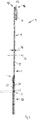
- Fig. 1
- shows a schematic front view of an embodiment for a spring member according to the invention.
- Fig. 2
- shows a schematic side view of the embodiment of
Figure 1 . - Fig. 3
- shows a schematic perspective view of an embodiment for an assembly according to the invention.
- Fig. 4
- shows a schematic perspective view of an embodiment for an electric switching device according to the invention.
- First, the design of a
spring member 1 according to the invention is explained with reference toFig. 1 and2 . - The
spring member 1 comprises acontact spring section 2 and areturn spring section 4. Both thecontact spring section 2 and thereturn spring section 4 extend away from acommon base portion 6. Thebase portion 6 comprises aproximal end 8 whereas thecontact spring section 2 extends from thebase portion 6 to adistal end 10. Thereturn spring section 4 extends alongside thecontact spring section 2. In particular, both thecontact spring section 2 and thereturn spring section 4 may run parallel to alengthwise direction 12 which extends from thepara-proximal end 8 to thedistal end 10 and parallel thereto. Both thecontact spring section 2 and thereturn spring section 4 are elongated in thelengthwise direction 12. Theirrespective widths width direction 18 are smaller than theirrespective lengths Figure 1 , perpendicular to thelengthwise direction 12. - The
spring member 1 is preferably a monolithic part made from sheet metal, such as copper or a copper alloy, by punching and/or bending. A material thickness 24 (seeFig. 2 ) in athickness direction 26 of the sheet metal is preferably constant. Thethickness direction 26 runs perpendicular to thelengthwise direction 12 and thewidth direction 18. - The
spring member 1 may comprise aterminal section 28 which also extends away from thebase portion 6. Theterminal section 28 may either extend in a direction perpendicular to thelengthwise direction 12 or parallel to thelengthwise direction 12. In the latter case, theterminal section 28 may extend away from thebase portion 6 to a direction opposite thedistal end 10. - The contact spring may comprise a main body 30, from which one or more spring arms 32 may branch off. If no spring arms 32 are provided, the main body itself may form a spring arm. The embodiment shown in
Figure 1 , a total of three spring arms are provided as a way of example only. - There may be provided at least one
lower spring arm 34 and at least oneupper spring arm 36. By way of example only, the embodiment ofFigure 1 has a pair oflower spring arms 34 and a singleupper spring arm 36. Alternatively, thespring member 1 may be provided with both a pair oflower spring arms 34 and a pair ofupper spring arms 36, or a singlelower spring arm 34 and a pair ofupper spring arms 36, or a singlelower spring arm 34 and a singleupper spring arm 36. - In particular, for high current applications, the utilization of a plurality of spring arms may ensure both that a cross-sectional area 37 of the
contact spring section 2 is large enough to reduce electric resistance and that the stiffness of thecontact spring section 2 is small enough to allow elastic deflection and proper adjustment of the elastic forces generated by a deflection of the spring arms. Anopening 38 at a location where one or more spring arms 32 branch off from the main body 30 may ensure width of the cross-sectional area 37 in thelengthwise direction 12 or along a current path directed through thecontact spring section 2. - The
contact spring section 2 further comprises a contactingspot 40. At the contactingspot 40, the contactingspring section 2 establishes contact with a counter contact (not shown) in an electric switching device. By being moved towards the counter contact, the spring member may close a circuit. By being moved away from the counter contact, the circuit may be interrupted. - The contacting
spot 40 is located at or close to thedistal end 10 for easier deflection. In particular, the contactingspot 40 is closer to thedistal end 10 than to thebase portion 6. Further, the contactingspot 40 may be located between thelower spring arm 34 and theupper spring arm 36. - The
return spring section 4 may consist of asingle leg 42 of at least approximately constant width and approximately constant thickness. At a free end 44 of thecontact spring section 2, aninclined portion 46 may be provided by bending apart 48 in the thickness direction, in particular to the side where the contactingspot 40 is situated on thecontact spring section 2. - The
return spring section 4 preferably extends in thelengthwise direction 12 beyond the location of the contactingspot 40 and/or at least beyond thelower spring arms 34, preferably, however, beyond all spring arms 32. - A stiffness of the
return spring section 4 is lower than the stiffness of thecontact spring section 2. If thecontact spring section 2 comprises spring arms 32, the stiffness of thereturn spring section 4 is lower than the combined stiffnesses of all spring arms 32. In particular, the stiffness of thereturn spring section 4 may be lower than the combined stiffnesses of two spring arms 32 and in particular be approximately equal to the stiffness of a single spring arm 32. - The
width 16 of thereturn spring section 4 is smaller than thewidth 14 of thecontact spring section 2, respectively its main body 30. Thewidth 16 of thereturn spring section 4 may be approximately equal to awidth 50 of a spring arm 32. As can be seen fromFigure 1 , there is no need to provide a contactingspot 40 on thereturn spring section 4. - Between the
return spring section 4 and thebase portion 6, there may be provided afoot section 52, where the stiffness is increased with respect to thereturn spring section 4. For example, the stiffness increase may be realized by providing thefoot section 52 with awidth 54 which is increased relative to thewidth 16 of thereturn spring section 4. Thewidth 54 of the foot section may, at least in a part 56 of thefoot section 52 decrease towards thereturn spring section 4. - It is preferred that the
return spring section 4 although being connected to thecontact spring section 2 monolithically by thebase portion 6, is uncoupled with respect to deflections from thecontact spring section 2. This may be accomplished by making thebase portion 6 much stiffer than both thecontact spring section 2 and thereturn spring section 4. - According to the embodiment shown in
Figures 1 and2 , thebase portion 6 has amain portion 58 and at least oneflap 60. Themain portion 58 is substantially flushed and co-planar with both thecontact spring section 2 and thereturn spring section 4. - The
flap 60 is preferably plastically deflected out of the plane of themain portion 58, to increase the stiffness of thebase portion 6. Theflap 60 is connected to themain portion 58 by abent portion 62. - The
flap 60 may lie in a plane which is parallel to themain portion 58. In particular, theflap 60 may abut themain portion 58 in that thebent portion 62 is bent by 180°. This is shown inFig. 2 in solid lines and results in an increased bent. Theflap 60 may also extend at an angle to themain portion 58, e.g. by bending thebent portion 62 by an angle of about 90°. This is shown in dotted lines. At or close to an end of thebase portion 6 opposite theproximal end 8, theflap 60 may be attached to themain portion 58, e.g. by welding, a positive lock or riveting. - The
flap 60 not only increases stiffness, but also increases the cross-sectional area 37 of thebase portion 6 so that its electric resistance with respect to high currents is decreased. Furthermore, bending theflap 60 away from themain portion 58 decreases the overall height of thespring member 1 in thelengthwise direction 12 between theproximal end 8 and adistal end 10, i.e. in that part that is contained in an electric switching device. - Next, an
assembly 63 comprising a spring member according to the invention and a drive transmission member such as the cradle of a cradle relay is explained with reference toFigure 3 . Only differences to the previous embodiment are noted. - In the embodiment of
Figure 3 , thecontact spring section 2 is provided with a pair ofupper spring arms 36. Further, thecontact spring section 2 comprises abead 59 between the contactingspot 40 and thebase portion 6, in particular between the set oflower spring arms 34 andupper spring arms 36. Furthermore, thefoot section 52 in the embodiment of thespring member 1 according toFigure 3 is much smaller than thefoot section 52 in the embodiments ofFigures 1 and2 . - The
drive transmission member 64 is provided with afirst support section 66 which is engaged to thecontact spring section 2, in particular a subset of the spring arms 32, such as anupper spring arm 36. Thefirst support section 66 is located in thelengthwise direction 12 at least approximately at the height of the contactingspot 40, close to thedistal end 10. More generally, it may be located between thelower spring arms 34 and theupper spring arms 36. In order to make the best use of the deflectability of thecontact spring section 2, however, thefirst support section 66 should be located as close as possible to thedistal end 10. - At the
first support section 66, thecontact spring 2 is held movable perpendicular to thelengthwise direction 12, in particular movable in thethickness direction 26, to allow for afree play 68 in this direction. Thefree play 68 is limited by two stops 70 formed by thedrive transmission member 64. - The
drive transmission member 64 further provides asecond support section 72 against which thereturn spring section 4 rests. Thesecond support section 72 preferably only consists of asupport surface 74 which faces thereturn spring section 4 approximately at the height of the contactingspot 40 in the lengthwise direction, as close to theinclined portion 46 as possible. At thesupport surface 74, thereturn spring section 4 may be held only by friction and the otherwise free to slide along thesupport surface 74 or lift of the same. - As can be seen from
Figure 3 , thedrive transmission member 64 may be provided, at itsend 76 facing thespring member 1 with aprotrusion 78 protruding towards thespring member 1. Thefirst support section 66 and thesecond support section 72 are preferably both located at thesame protrusion 78. - The
first support section 66 may comprise ahook 80 which forms one or two of the stops 70. Further, ashoulder 82 may be provided by thehook 80 or theprotrusion 78 respectively. Thesupport surface 74 is located on thisshoulder 82. Preferably, thesupport surface 74 and one of the stops 70, in particular the stop 70 closer to the end of the end of theprotrusion 78 are aligned to each other and lie within the same plane. - As shown in
Figure 4 , thespring member 1 and/or the assembly may be incorporated in anelectric switching device 84 such as a cradle relay. - In such a configuration, the
drive transmission member 64 may be coupled at oneend 86 to thespring member 1 and at its other end 88 to adriving section 90. - The driving
section 90 may be a magnetic drive system comprising acoil 92, ayoke 94, and an armature 96, which, inFigure 4 , are only schematically represented. - The
drive transmission member 64 is held movable, in particular, slidable in adirection 97 extending from oneend 86 to the other end 88 in theelectric switching device 84. Thebase portion 6 of thespring member 1 is mounted fixedly in theelectric switching device 84. - In an initial state, the armature 96 is pulled towards the
coil 92. Thedrive transmission 64member 64 is pushed by the armature 96 towards thespring member 1, deflecting both thereturn spring section 2, and, after thefree play 68 is exhausted, thecontact spring section 2. By this, thecontact spring section 2 is pressed against a preferably fixed counter contact (not shown). Using an over stroke, thedrive transmission member 64 is moved over the point where the contactingspot 40 is in contact with the counter contact so that the spring arms 32 are deflected and resiliently press the contactingspot 40 against the counter contact. The drivingforce 98 exerted by the drivingsection 90 is counteracted by at least thereturn force 100 exerted by the deflectedreturn spring section 4 and preferably also by the deflection of the spring arms 32. - If the armature is released, both the
return spring section 4 and thecontact spring section 2 will initially move the armature 96 away from thecoil 92. Thereturn spring section 4 will continue to do so, even after thecontact section 2, respectively its spring arms 32 can relax because the zone of thefree play 68 is reached. As thecontact spring section 2 and thereturn spring section 4 are de-coupled from each other by thestiff base portion 6 and in addition by therigid fixation 102 of thebase portion 6 along its length in theelectric switching device 84, thereturn force 100 is independent of the deflection of thecontact spring section 2. - Thus, an additional
return spring section 4 acting directly on the armature 96 can be omitted. -
- 1
- Spring member
- 2
- Contact spring section
- 4
- Return spring section
- 6
- Base portion
- 8
- Proximal end
- 10
- Distal end
- 12
- Lengthwise direction
- 14
- Width of contact spring section
- 16
- Width of return spring section
- 18
- Width direction
- 20
- Length of contact spring section
- 22
- Length of return spring section
- 24
- Thickness
- 26
- Thickness direction
- 28
- Terminal section
- 30
- Main body
- 32
- Spring arms
- 34
- Lower spring arm
- 36
- Upper spring arm
- 37
- Cross-sectional area of contact spring
- 38
- Opening
- 40
- Contacting spot
- 42
- Leg of contact spring section
- 44
- Free end of contact spring section
- 46
- Inclined portion of a bended part
- 48
- Bended part
- 50
- Widths of a spring arm
- 52
- Foot section
- 54
- Width of foot section
- 56
- Part of foot section
- 58
- Main portion of base portion
- 59
- Bead
- 60
- Flap of base portion
- 62
- Bent portion between main portion and flap
- 63
- Assembly
- 64
- Drive transmission member
- 66
- First support section
- 68
- Free play
- 70
- Stops
- 72
- Second support section
- 74
- Support surface
- 76
- End of drive transmission member facing spring member
- 78
- Protrusion at drive transmission member
- 80
- Hook
- 82
- Shoulder at protrusion
- 84
- Electric switching device
- 86
- One end of drive transmission member
- 88
- Other end of drive transmission member
- 90
- Driving section
- 92
- Coil
- 94
- Yoke
- 96
- Armature
- 97
- Direction of movement of drive transmission member
- 98
- Driving force
- 100
- Return force
- 102
- Fixation of base portion in electric switching device
Claims (15)
- Electric switching device (84) such as cradle relay, comprising at least one spring member (1), said spring member (1) comprising a distal end (10), a proximal end (8) opposite said distal end (10), a base portion (6), said base portion (6) comprising said proximal end (8), and a contact spring section (2), said contact spring section (2) extending from said base portion (6) to said distal end (10) and being provided with a contacting spot (40), characterized in that said spring member (1) further comprises a return spring section (4) extending from said base portion (6) alongside said contact spring section (2).
- Electric switching device (84) according to claim 1, wherein said return spring section (4) has a return spring stiffness and said contact spring section (2) has a contact spring stiffness, said return spring stiffness being smaller than said contact spring stiffness.
- Electric switching device (84) according to claim 1 or 2, wherein, in a width direction (18) perpendicular to a lengthwise direction (12) of said spring member (1), said lengthwise direction (12) extending between said distal end (10) and said proximal end (8), said contact spring section (2) is wider than said return spring section (4).
- Electric switching device (84) according to any one of claims 1 to 3, wherein said return spring section (4) extends at least up to said contacting spot (40) in the lengthwise direction (12).
- Electric switching device (84) according to any one of claims 1 to 4, wherein said return spring section (4) is provided with an inclined portion (46) at said distal end (10).
- Electric switching device (84) according to any one of claims 1 to 5, wherein said spring member (1) further comprises a foot section (52), said foot section (52) being located where said return spring section (4) is connected to said base portion (6) and wherein said foot section (52) is enforced with respect to said return spring section (4).
- Electric switching device (84) according to claim 6, wherein said foot section (52) has a width (54), said width (54) decreasing towards said return spring section (4).
- Electric switching device (84) according to any one of claims 1 to 7, wherein said base portion (6) comprises a main portion (58) and at least one flap (60), said flap (60) being connected to said main portion (58) by a bent portion (62).
- Electric switching device (84) according to any one of claims 1 to 8, the electric switching device (84) further comprising a drive transmission member (64) providing a first support section (66), said first support section (66) being engaged with said contact spring section (2), and wherein said drive transmission member (64) further comprises a second support section (72), said return spring section (4) resting against said second support section (72).
- Electric switching device (84) according to claim 9, wherein said drive transmission member (64) comprises a protrusion (78), said protrusion (78) extending towards said spring member (1), and wherein said first support section (66) and said second support section (72) are located on said protrusion (78).
- Electric switching device (84) according to claim 9 or 10, wherein said first support section (66) is located adjacent said second support section (72).
- Electric switching device (84) according to any one of claims 9 to 11, wherein said contact spring section (2) is coupled to said drive transmission member (64) in a manner allowing a limited free play (68) in one direction (26) between said contact spring section (2) and said drive transmission member (64).
- Electric switching device (84) according to any one of claims 9 to 12, wherein said first support section (66) comprises a stop (70) and said second support section (72) comprises a support surface (74), said stop (70) and said support surface (74) being located in the same plane.
- Electric switching device (84) according to any one of claims 1 to 13, the electric switching device (84) further comprising a driving section (90), said driving section (90) and said spring member (1) being coupled to said drive transmission member (64), said driving section (90) being adapted to generate a driving force (98) acting on said drive transmission member (64), wherein said return spring section (4) is adapted to generate a return force (100), said return force (100) acting on said drive transmission member (64) and counter-acting said driving force (98).
- Electric switching device (84) according to claim 14, wherein said return force (100) is independent of a deflection of said contact spring section (2), said deflection occurring during operational said electric switching device (84).
Priority Applications (5)
| Application Number | Priority Date | Filing Date | Title |
|---|---|---|---|
| EP15153202.5A EP3051562B1 (en) | 2015-01-30 | 2015-01-30 | Spring Member for an Electric Switching Device such as a Cradle Relay |
| JP2017538975A JP6718878B2 (en) | 2015-01-30 | 2016-01-29 | Spring members for electric switching devices such as cradle relays |
| PCT/EP2016/052005 WO2016120485A1 (en) | 2015-01-30 | 2016-01-29 | Spring member for an electric switching device such as a cradle relay |
| CN201680007486.9A CN107210165B (en) | 2015-01-30 | 2016-01-29 | Spring member for an electrical switching apparatus such as a cradle relay |
| US15/661,812 US10665407B2 (en) | 2015-01-30 | 2017-07-27 | Spring member for an electric switching device such as a cradle relay |
Applications Claiming Priority (1)
| Application Number | Priority Date | Filing Date | Title |
|---|---|---|---|
| EP15153202.5A EP3051562B1 (en) | 2015-01-30 | 2015-01-30 | Spring Member for an Electric Switching Device such as a Cradle Relay |
Publications (2)
| Publication Number | Publication Date |
|---|---|
| EP3051562A1 EP3051562A1 (en) | 2016-08-03 |
| EP3051562B1 true EP3051562B1 (en) | 2018-12-26 |
Family
ID=52444162
Family Applications (1)
| Application Number | Title | Priority Date | Filing Date |
|---|---|---|---|
| EP15153202.5A Active EP3051562B1 (en) | 2015-01-30 | 2015-01-30 | Spring Member for an Electric Switching Device such as a Cradle Relay |
Country Status (5)
| Country | Link |
|---|---|
| US (1) | US10665407B2 (en) |
| EP (1) | EP3051562B1 (en) |
| JP (1) | JP6718878B2 (en) |
| CN (1) | CN107210165B (en) |
| WO (1) | WO2016120485A1 (en) |
Families Citing this family (3)
| Publication number | Priority date | Publication date | Assignee | Title |
|---|---|---|---|---|
| EP3640963B1 (en) * | 2018-10-15 | 2026-03-25 | TE Connectivity Austria GmbH | Kit and method for the assembly of at least two variants of a relay and contact spring for a relay |
| JP7353859B2 (en) * | 2019-08-09 | 2023-10-02 | 株式会社日本マイクロニクス | Electrical contacts and electrical connection devices |
| EP3836170B1 (en) * | 2019-12-11 | 2024-03-20 | TE Connectivity Austria GmbH | Spring assembly for biasing an armature of a switching device, and switching device comprising such spring assembly |
Family Cites Families (8)
| Publication number | Priority date | Publication date | Assignee | Title |
|---|---|---|---|---|
| AT386696B (en) * | 1980-12-03 | 1988-09-26 | Schrack Elektronik Ag | CONTACT SPRING SET |
| JPS63175312A (en) * | 1987-01-14 | 1988-07-19 | 松下電工株式会社 | Contactor |
| JP3383984B2 (en) * | 1992-05-14 | 2003-03-10 | オムロン株式会社 | Electromagnetic relay |
| AT410856B (en) * | 1994-07-08 | 2003-08-25 | Tyco Electronics Austria Gmbh | RELAY |
| JP2000285783A (en) * | 1999-03-31 | 2000-10-13 | Omron Corp | Electromagnetic relay |
| JP4168733B2 (en) * | 2002-11-12 | 2008-10-22 | オムロン株式会社 | Electromagnetic relay |
| DE102010063229A1 (en) | 2010-12-16 | 2012-06-21 | Tyco Electronics Austria Gmbh | Relay with improved contact spring |
| DE102013212607B4 (en) * | 2013-06-28 | 2024-02-01 | Te Connectivity Austria Gmbh | Switch contact assembly and method for producing same |
-
2015
- 2015-01-30 EP EP15153202.5A patent/EP3051562B1/en active Active
-
2016
- 2016-01-29 JP JP2017538975A patent/JP6718878B2/en active Active
- 2016-01-29 CN CN201680007486.9A patent/CN107210165B/en active Active
- 2016-01-29 WO PCT/EP2016/052005 patent/WO2016120485A1/en not_active Ceased
-
2017
- 2017-07-27 US US15/661,812 patent/US10665407B2/en active Active
Non-Patent Citations (1)
| Title |
|---|
| None * |
Also Published As
| Publication number | Publication date |
|---|---|
| CN107210165A (en) | 2017-09-26 |
| US10665407B2 (en) | 2020-05-26 |
| US20170323750A1 (en) | 2017-11-09 |
| WO2016120485A1 (en) | 2016-08-04 |
| JP6718878B2 (en) | 2020-07-08 |
| CN107210165B (en) | 2020-03-31 |
| JP2018503953A (en) | 2018-02-08 |
| EP3051562A1 (en) | 2016-08-03 |
Similar Documents
| Publication | Publication Date | Title |
|---|---|---|
| US8432241B2 (en) | Contact arrangement having a bent cord, relay having a contact arrangement and method for assembling a relay | |
| JP6622188B2 (en) | Electrical switch device with improved Lorentz force bias | |
| EP2782110B1 (en) | Lorentz force activated electric switching device | |
| EP3051562A1 (en) | Spring Member for an Electric Switching Device such as a Cradle Relay | |
| US20210012990A1 (en) | Armature of relay | |
| US20210012991A1 (en) | Armature of relay | |
| CN107924772B (en) | Contact Strip Units and Relays | |
| CN102138192B (en) | Contact assembly of relay and relay with contact assembly | |
| JP5056571B2 (en) | Circuit breaker | |
| US7939992B2 (en) | Electrical switch element, particularly a relay, with swivelling lever switch mechanism | |
| US10607799B2 (en) | Electrical switch having a direct armature coupling | |
| JP2005216853A (en) | Heavy duty relay | |
| CN209591932U (en) | A kind of magnetic latching relay that current-carrying capability is strong | |
| US11887797B2 (en) | Electrical switching element comprising a direct armature coupling | |
| CN220367859U (en) | Push piece and movable spring assembly matching movable structure | |
| US11776783B2 (en) | Kit and method for the assembly of at least two variants of a relay and contact spring for a relay | |
| US20160379785A1 (en) | Electromagnetic Relay | |
| JPWO2019180934A1 (en) | Contact switch | |
| JP2025523207A (en) | relay | |
| CN110033996A (en) | A kind of magnetic latching relay that current-carrying capability is strong | |
| JPH06162901A (en) | Electromagnetic relay |
Legal Events
| Date | Code | Title | Description |
|---|---|---|---|
| PUAI | Public reference made under article 153(3) epc to a published international application that has entered the european phase |
Free format text: ORIGINAL CODE: 0009012 |
|
| AK | Designated contracting states |
Kind code of ref document: A1 Designated state(s): AL AT BE BG CH CY CZ DE DK EE ES FI FR GB GR HR HU IE IS IT LI LT LU LV MC MK MT NL NO PL PT RO RS SE SI SK SM TR |
|
| AX | Request for extension of the european patent |
Extension state: BA ME |
|
| STAA | Information on the status of an ep patent application or granted ep patent |
Free format text: STATUS: REQUEST FOR EXAMINATION WAS MADE |
|
| 17P | Request for examination filed |
Effective date: 20170203 |
|
| RBV | Designated contracting states (corrected) |
Designated state(s): AL AT BE BG CH CY CZ DE DK EE ES FI FR GB GR HR HU IE IS IT LI LT LU LV MC MK MT NL NO PL PT RO RS SE SI SK SM TR |
|
| STAA | Information on the status of an ep patent application or granted ep patent |
Free format text: STATUS: EXAMINATION IS IN PROGRESS |
|
| 17Q | First examination report despatched |
Effective date: 20170612 |
|
| GRAP | Despatch of communication of intention to grant a patent |
Free format text: ORIGINAL CODE: EPIDOSNIGR1 |
|
| STAA | Information on the status of an ep patent application or granted ep patent |
Free format text: STATUS: GRANT OF PATENT IS INTENDED |
|
| RIC1 | Information provided on ipc code assigned before grant |
Ipc: H01H 3/48 20060101ALN20180621BHEP Ipc: H01H 50/64 20060101ALN20180621BHEP Ipc: H01H 50/56 20060101AFI20180621BHEP |
|
| INTG | Intention to grant announced |
Effective date: 20180711 |
|
| GRAS | Grant fee paid |
Free format text: ORIGINAL CODE: EPIDOSNIGR3 |
|
| GRAA | (expected) grant |
Free format text: ORIGINAL CODE: 0009210 |
|
| STAA | Information on the status of an ep patent application or granted ep patent |
Free format text: STATUS: THE PATENT HAS BEEN GRANTED |
|
| AK | Designated contracting states |
Kind code of ref document: B1 Designated state(s): AL AT BE BG CH CY CZ DE DK EE ES FI FR GB GR HR HU IE IS IT LI LT LU LV MC MK MT NL NO PL PT RO RS SE SI SK SM TR |
|
| REG | Reference to a national code |
Ref country code: GB Ref legal event code: FG4D |
|
| REG | Reference to a national code |
Ref country code: CH Ref legal event code: EP |
|
| REG | Reference to a national code |
Ref country code: AT Ref legal event code: REF Ref document number: 1082581 Country of ref document: AT Kind code of ref document: T Effective date: 20190115 |
|
| REG | Reference to a national code |
Ref country code: DE Ref legal event code: R096 Ref document number: 602015022095 Country of ref document: DE |
|
| REG | Reference to a national code |
Ref country code: IE Ref legal event code: FG4D |
|
| PG25 | Lapsed in a contracting state [announced via postgrant information from national office to epo] |
Ref country code: NO Free format text: LAPSE BECAUSE OF FAILURE TO SUBMIT A TRANSLATION OF THE DESCRIPTION OR TO PAY THE FEE WITHIN THE PRESCRIBED TIME-LIMIT Effective date: 20190326 Ref country code: FI Free format text: LAPSE BECAUSE OF FAILURE TO SUBMIT A TRANSLATION OF THE DESCRIPTION OR TO PAY THE FEE WITHIN THE PRESCRIBED TIME-LIMIT Effective date: 20181226 Ref country code: BG Free format text: LAPSE BECAUSE OF FAILURE TO SUBMIT A TRANSLATION OF THE DESCRIPTION OR TO PAY THE FEE WITHIN THE PRESCRIBED TIME-LIMIT Effective date: 20190326 Ref country code: LT Free format text: LAPSE BECAUSE OF FAILURE TO SUBMIT A TRANSLATION OF THE DESCRIPTION OR TO PAY THE FEE WITHIN THE PRESCRIBED TIME-LIMIT Effective date: 20181226 Ref country code: HR Free format text: LAPSE BECAUSE OF FAILURE TO SUBMIT A TRANSLATION OF THE DESCRIPTION OR TO PAY THE FEE WITHIN THE PRESCRIBED TIME-LIMIT Effective date: 20181226 Ref country code: LV Free format text: LAPSE BECAUSE OF FAILURE TO SUBMIT A TRANSLATION OF THE DESCRIPTION OR TO PAY THE FEE WITHIN THE PRESCRIBED TIME-LIMIT Effective date: 20181226 |
|
| REG | Reference to a national code |
Ref country code: NL Ref legal event code: MP Effective date: 20181226 |
|
| REG | Reference to a national code |
Ref country code: LT Ref legal event code: MG4D |
|
| PG25 | Lapsed in a contracting state [announced via postgrant information from national office to epo] |
Ref country code: RS Free format text: LAPSE BECAUSE OF FAILURE TO SUBMIT A TRANSLATION OF THE DESCRIPTION OR TO PAY THE FEE WITHIN THE PRESCRIBED TIME-LIMIT Effective date: 20181226 Ref country code: AL Free format text: LAPSE BECAUSE OF FAILURE TO SUBMIT A TRANSLATION OF THE DESCRIPTION OR TO PAY THE FEE WITHIN THE PRESCRIBED TIME-LIMIT Effective date: 20181226 Ref country code: SE Free format text: LAPSE BECAUSE OF FAILURE TO SUBMIT A TRANSLATION OF THE DESCRIPTION OR TO PAY THE FEE WITHIN THE PRESCRIBED TIME-LIMIT Effective date: 20181226 Ref country code: GR Free format text: LAPSE BECAUSE OF FAILURE TO SUBMIT A TRANSLATION OF THE DESCRIPTION OR TO PAY THE FEE WITHIN THE PRESCRIBED TIME-LIMIT Effective date: 20190327 |
|
| REG | Reference to a national code |
Ref country code: AT Ref legal event code: MK05 Ref document number: 1082581 Country of ref document: AT Kind code of ref document: T Effective date: 20181226 |
|
| PG25 | Lapsed in a contracting state [announced via postgrant information from national office to epo] |
Ref country code: NL Free format text: LAPSE BECAUSE OF FAILURE TO SUBMIT A TRANSLATION OF THE DESCRIPTION OR TO PAY THE FEE WITHIN THE PRESCRIBED TIME-LIMIT Effective date: 20181226 |
|
| PG25 | Lapsed in a contracting state [announced via postgrant information from national office to epo] |
Ref country code: ES Free format text: LAPSE BECAUSE OF FAILURE TO SUBMIT A TRANSLATION OF THE DESCRIPTION OR TO PAY THE FEE WITHIN THE PRESCRIBED TIME-LIMIT Effective date: 20181226 Ref country code: PL Free format text: LAPSE BECAUSE OF FAILURE TO SUBMIT A TRANSLATION OF THE DESCRIPTION OR TO PAY THE FEE WITHIN THE PRESCRIBED TIME-LIMIT Effective date: 20181226 Ref country code: IT Free format text: LAPSE BECAUSE OF FAILURE TO SUBMIT A TRANSLATION OF THE DESCRIPTION OR TO PAY THE FEE WITHIN THE PRESCRIBED TIME-LIMIT Effective date: 20181226 Ref country code: PT Free format text: LAPSE BECAUSE OF FAILURE TO SUBMIT A TRANSLATION OF THE DESCRIPTION OR TO PAY THE FEE WITHIN THE PRESCRIBED TIME-LIMIT Effective date: 20190426 Ref country code: CZ Free format text: LAPSE BECAUSE OF FAILURE TO SUBMIT A TRANSLATION OF THE DESCRIPTION OR TO PAY THE FEE WITHIN THE PRESCRIBED TIME-LIMIT Effective date: 20181226 |
|
| PG25 | Lapsed in a contracting state [announced via postgrant information from national office to epo] |
Ref country code: RO Free format text: LAPSE BECAUSE OF FAILURE TO SUBMIT A TRANSLATION OF THE DESCRIPTION OR TO PAY THE FEE WITHIN THE PRESCRIBED TIME-LIMIT Effective date: 20181226 Ref country code: SM Free format text: LAPSE BECAUSE OF FAILURE TO SUBMIT A TRANSLATION OF THE DESCRIPTION OR TO PAY THE FEE WITHIN THE PRESCRIBED TIME-LIMIT Effective date: 20181226 Ref country code: EE Free format text: LAPSE BECAUSE OF FAILURE TO SUBMIT A TRANSLATION OF THE DESCRIPTION OR TO PAY THE FEE WITHIN THE PRESCRIBED TIME-LIMIT Effective date: 20181226 Ref country code: IS Free format text: LAPSE BECAUSE OF FAILURE TO SUBMIT A TRANSLATION OF THE DESCRIPTION OR TO PAY THE FEE WITHIN THE PRESCRIBED TIME-LIMIT Effective date: 20190426 Ref country code: SK Free format text: LAPSE BECAUSE OF FAILURE TO SUBMIT A TRANSLATION OF THE DESCRIPTION OR TO PAY THE FEE WITHIN THE PRESCRIBED TIME-LIMIT Effective date: 20181226 |
|
| REG | Reference to a national code |
Ref country code: CH Ref legal event code: PL |
|
| REG | Reference to a national code |
Ref country code: DE Ref legal event code: R097 Ref document number: 602015022095 Country of ref document: DE |
|
| PG25 | Lapsed in a contracting state [announced via postgrant information from national office to epo] |
Ref country code: LU Free format text: LAPSE BECAUSE OF NON-PAYMENT OF DUE FEES Effective date: 20190130 |
|
| REG | Reference to a national code |
Ref country code: BE Ref legal event code: MM Effective date: 20190131 |
|
| REG | Reference to a national code |
Ref country code: IE Ref legal event code: MM4A |
|
| PG25 | Lapsed in a contracting state [announced via postgrant information from national office to epo] |
Ref country code: DK Free format text: LAPSE BECAUSE OF FAILURE TO SUBMIT A TRANSLATION OF THE DESCRIPTION OR TO PAY THE FEE WITHIN THE PRESCRIBED TIME-LIMIT Effective date: 20181226 Ref country code: AT Free format text: LAPSE BECAUSE OF FAILURE TO SUBMIT A TRANSLATION OF THE DESCRIPTION OR TO PAY THE FEE WITHIN THE PRESCRIBED TIME-LIMIT Effective date: 20181226 Ref country code: MC Free format text: LAPSE BECAUSE OF FAILURE TO SUBMIT A TRANSLATION OF THE DESCRIPTION OR TO PAY THE FEE WITHIN THE PRESCRIBED TIME-LIMIT Effective date: 20181226 |
|
| PLBE | No opposition filed within time limit |
Free format text: ORIGINAL CODE: 0009261 |
|
| STAA | Information on the status of an ep patent application or granted ep patent |
Free format text: STATUS: NO OPPOSITION FILED WITHIN TIME LIMIT |
|
| PG25 | Lapsed in a contracting state [announced via postgrant information from national office to epo] |
Ref country code: BE Free format text: LAPSE BECAUSE OF NON-PAYMENT OF DUE FEES Effective date: 20190131 |
|
| 26N | No opposition filed |
Effective date: 20190927 |
|
| PG25 | Lapsed in a contracting state [announced via postgrant information from national office to epo] |
Ref country code: CH Free format text: LAPSE BECAUSE OF NON-PAYMENT OF DUE FEES Effective date: 20190131 Ref country code: LI Free format text: LAPSE BECAUSE OF NON-PAYMENT OF DUE FEES Effective date: 20190131 |
|
| PG25 | Lapsed in a contracting state [announced via postgrant information from national office to epo] |
Ref country code: IE Free format text: LAPSE BECAUSE OF NON-PAYMENT OF DUE FEES Effective date: 20190130 |
|
| PG25 | Lapsed in a contracting state [announced via postgrant information from national office to epo] |
Ref country code: SI Free format text: LAPSE BECAUSE OF FAILURE TO SUBMIT A TRANSLATION OF THE DESCRIPTION OR TO PAY THE FEE WITHIN THE PRESCRIBED TIME-LIMIT Effective date: 20181226 |
|
| PG25 | Lapsed in a contracting state [announced via postgrant information from national office to epo] |
Ref country code: TR Free format text: LAPSE BECAUSE OF FAILURE TO SUBMIT A TRANSLATION OF THE DESCRIPTION OR TO PAY THE FEE WITHIN THE PRESCRIBED TIME-LIMIT Effective date: 20181226 |
|
| PG25 | Lapsed in a contracting state [announced via postgrant information from national office to epo] |
Ref country code: MT Free format text: LAPSE BECAUSE OF NON-PAYMENT OF DUE FEES Effective date: 20190130 |
|
| PG25 | Lapsed in a contracting state [announced via postgrant information from national office to epo] |
Ref country code: CY Free format text: LAPSE BECAUSE OF FAILURE TO SUBMIT A TRANSLATION OF THE DESCRIPTION OR TO PAY THE FEE WITHIN THE PRESCRIBED TIME-LIMIT Effective date: 20181226 |
|
| PG25 | Lapsed in a contracting state [announced via postgrant information from national office to epo] |
Ref country code: HU Free format text: LAPSE BECAUSE OF FAILURE TO SUBMIT A TRANSLATION OF THE DESCRIPTION OR TO PAY THE FEE WITHIN THE PRESCRIBED TIME-LIMIT; INVALID AB INITIO Effective date: 20150130 |
|
| PG25 | Lapsed in a contracting state [announced via postgrant information from national office to epo] |
Ref country code: MK Free format text: LAPSE BECAUSE OF FAILURE TO SUBMIT A TRANSLATION OF THE DESCRIPTION OR TO PAY THE FEE WITHIN THE PRESCRIBED TIME-LIMIT Effective date: 20181226 |
|
| REG | Reference to a national code |
Ref country code: DE Ref legal event code: R081 Ref document number: 602015022095 Country of ref document: DE Owner name: TE CONNECTIVITY AUSTRIA GMBH, AT Free format text: FORMER OWNER: TYCO ELECTRONICS AUSTRIA GMBH, WIEN, AT |
|
| PGFP | Annual fee paid to national office [announced via postgrant information from national office to epo] |
Ref country code: GB Payment date: 20251211 Year of fee payment: 12 |
|
| PGFP | Annual fee paid to national office [announced via postgrant information from national office to epo] |
Ref country code: FR Payment date: 20251208 Year of fee payment: 12 |
|
| PGFP | Annual fee paid to national office [announced via postgrant information from national office to epo] |
Ref country code: DE Payment date: 20251203 Year of fee payment: 12 |