EP3051148A1 - Actuator with a composite piston rod and a metallic piston - Google Patents
Actuator with a composite piston rod and a metallic piston Download PDFInfo
- Publication number
- EP3051148A1 EP3051148A1 EP16153491.2A EP16153491A EP3051148A1 EP 3051148 A1 EP3051148 A1 EP 3051148A1 EP 16153491 A EP16153491 A EP 16153491A EP 3051148 A1 EP3051148 A1 EP 3051148A1
- Authority
- EP
- European Patent Office
- Prior art keywords
- actuator
- embedded bolt
- tapered end
- composite
- threaded end
- Prior art date
- Legal status (The legal status is an assumption and is not a legal conclusion. Google has not performed a legal analysis and makes no representation as to the accuracy of the status listed.)
- Granted
Links
Images
Classifications
-
- F—MECHANICAL ENGINEERING; LIGHTING; HEATING; WEAPONS; BLASTING
- F15—FLUID-PRESSURE ACTUATORS; HYDRAULICS OR PNEUMATICS IN GENERAL
- F15B—SYSTEMS ACTING BY MEANS OF FLUIDS IN GENERAL; FLUID-PRESSURE ACTUATORS, e.g. SERVOMOTORS; DETAILS OF FLUID-PRESSURE SYSTEMS, NOT OTHERWISE PROVIDED FOR
- F15B15/00—Fluid-actuated devices for displacing a member from one position to another; Gearing associated therewith
- F15B15/08—Characterised by the construction of the motor unit
- F15B15/14—Characterised by the construction of the motor unit of the straight-cylinder type
- F15B15/1423—Component parts; Constructional details
- F15B15/1457—Piston rods
-
- B—PERFORMING OPERATIONS; TRANSPORTING
- B64—AIRCRAFT; AVIATION; COSMONAUTICS
- B64C—AEROPLANES; HELICOPTERS
- B64C25/00—Alighting gear
- B64C25/02—Undercarriages
- B64C25/08—Undercarriages non-fixed, e.g. jettisonable
- B64C25/10—Undercarriages non-fixed, e.g. jettisonable retractable, foldable, or the like
- B64C25/18—Operating mechanisms
- B64C25/22—Operating mechanisms fluid
-
- F—MECHANICAL ENGINEERING; LIGHTING; HEATING; WEAPONS; BLASTING
- F15—FLUID-PRESSURE ACTUATORS; HYDRAULICS OR PNEUMATICS IN GENERAL
- F15B—SYSTEMS ACTING BY MEANS OF FLUIDS IN GENERAL; FLUID-PRESSURE ACTUATORS, e.g. SERVOMOTORS; DETAILS OF FLUID-PRESSURE SYSTEMS, NOT OTHERWISE PROVIDED FOR
- F15B15/00—Fluid-actuated devices for displacing a member from one position to another; Gearing associated therewith
- F15B15/08—Characterised by the construction of the motor unit
- F15B15/14—Characterised by the construction of the motor unit of the straight-cylinder type
- F15B15/1423—Component parts; Constructional details
- F15B15/1447—Pistons; Piston to piston rod assemblies
-
- F—MECHANICAL ENGINEERING; LIGHTING; HEATING; WEAPONS; BLASTING
- F15—FLUID-PRESSURE ACTUATORS; HYDRAULICS OR PNEUMATICS IN GENERAL
- F15B—SYSTEMS ACTING BY MEANS OF FLUIDS IN GENERAL; FLUID-PRESSURE ACTUATORS, e.g. SERVOMOTORS; DETAILS OF FLUID-PRESSURE SYSTEMS, NOT OTHERWISE PROVIDED FOR
- F15B15/00—Fluid-actuated devices for displacing a member from one position to another; Gearing associated therewith
- F15B15/08—Characterised by the construction of the motor unit
- F15B15/14—Characterised by the construction of the motor unit of the straight-cylinder type
- F15B15/1423—Component parts; Constructional details
- F15B15/1447—Pistons; Piston to piston rod assemblies
- F15B15/1452—Piston sealings
Definitions
- the present disclosure relates generally to actuators and more specifically to actuators having composite actuator piston tubes.
- actuators including, for example, to deploy nose, body, and/or wheel landing gear systems.
- Conventional actuator components are made of metallic materials and often comprise complex geometries and high strengths. However, these metallic components are typically heavy.
- An actuator in accordance with various embodiments may comprise a composite actuator rod tube having a tapered end, an embedded bolt having a threaded end, and a nut configured to engage with the threaded end of the embedded bolt.
- the actuator may comprise a piston head concentrically surrounding the tapered end of the composite actuator rod tube.
- a locking cup washer may concentrically surround a portion of the threaded end of the embedded bolt.
- the locking cup washer may comprise a key configured to engage with a slot of the threaded end of the embedded bolt.
- a jam nut may be engaged with the threaded end of the embedded bolt proximate the locking cup washer.
- the piston head may comprise a sealing groove and/or a bearing groove.
- the embedded bolt may be positioned within and bonded to the tapered end of the composite actuator rod tube.
- the threaded end of the embedded bolt may comprise a flat segment.
- a method for forming a composite actuator rod in accordance with various embodiments may comprise forming a composite actuator rod tube having a tapered end concentrically surrounding an embedded bolt, and bonding the embedded bolt to the tapered end.
- the embedded bolt may comprise a flat segment.
- the method may further comprise concentrically surrounding the tapered end with a piston head and securing it to the tapered end with a nut.
- the method may further comprise concentrically surrounding the threaded end of the embedded bolt with a locking cup washer comprising a key configured to engage with a slot of the threaded end of the embedded bolt.
- the method may further comprise engaging the threaded end of the embedded bolt with a jam nut and positioning the jam nut proximate the locking cup washer.
- the present disclosure describes actuators having a composite actuator rod. Such actuators may be used in aircraft systems, such as, for example, landing gear systems. However, the systems and methods of the present disclosure may be suitable for use in non-aircraft systems as well.
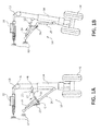
- landing gear 10 includes a strut 14 supporting wheels 16.
- Strut 14 is rotatable about a pivot, which is provided by an airframe 12, in response to an extend/retract actuator 18 applying a force to an arm 19.
- a linkage 20 may connect a lower portion of strut 14 to airframe 12, for example.
- a lock-stay 22 may be interconnected between linkage 20 and strut 14 to lock landing gear 10 in a deployed position until landing gear retraction is commanded.
- FIG 1A landing gear 10 is shown in the deployed position.
- the example lock-stay 22 includes first and second links 21, 23 pivotally secured to one another at a joint D.
- One end of first link 21 is connected to strut 14 at pivot B.
- a portion of second link 23 is connected to linkage 20 at pivot C.
- a biasing member 26 is arranged between lock-stay 22 and linkage 20 to bias lock-stay 22 to the locked position.
- An unlock actuator 24 is interconnected between linkage 20 and lock-stay 22 to pull joint D from over-center, as depicted by the arrow in Figure 1B , so that extend/retract actuator 18 can move landing gear 10 to a stowed position.
- Actuator 30 may comprise, for example, an extend/retract actuator 18 or an unlock actuator 24 (as illustrated in Figures 1 A and 1B ), or any other type of actuator suitable for use in body-type landing gear systems. Further, actuator 30 may comprise an actuator suitable for use in other systems, including flight control systems, wing and nose landing gear systems, and any other system which utilizes one or more actuators, including non-aircraft systems. Actuator 30 may comprise an actuator body 31 into which an actuator rod tube 33 (also referred to as an actuator piston) retracts and extends.
- an actuator rod tube 33 also referred to as an actuator piston
- Actuator 30 may comprise, for example an extend/retract actuator 18 or an unlock actuator 24 (as illustrated in Figures 1A and 1B ), or any other type of actuator suitable for use in body-type landing gear systems. Further, actuator 30 may comprise an actuator suitable for use in other systems, including flight control systems, wing and nose landing gear systems, and any other system which utilize one or more actuators, including non-aircraft systems.
- actuator 30 comprises a composite actuator rod tube 34.
- Composite actuator rod tube 34 may comprise, for example, a lightweight polymer matrix composite such as a carbon fiber composite material or a hydrocarbon fiber composite material.
- a lightweight polymer matrix composite such as a carbon fiber composite material or a hydrocarbon fiber composite material.
- composite materials provide reduced weight over traditional metal components, it may be difficult to couple composite materials to metal components.
- Conventional methods of attaching composite materials to other materials, such as threading or drilling holes in the composite material may significantly reduce the strength of the composite material. Therefore, methods and apparatus for connecting composite material components (such as composite actuator rod tube 34) to other components (such as metallic components) may be desirable.
- Composite actuator rod tube 34 may comprise a tapered end 36.
- tapered end 36 is formed of a lightweight polymer matrix composite material.
- tapered end 36 may comprise the same material as composite actuator rod tube 34.
- Tapered end 36 may be configured to provide a tapered surface to engage with a metal component of actuator 30.
- a metal component may be secured against and held within tapered end 36, eliminating the need for threading or drilling of tapered end 36 and/or actuator rod tube 34, which would reduce the strength of and/or compromise the structural integrity of actuator rod tube 34.
- Composite actuator rod tube 34 and tapered end 36 may be formed by laying composite sheets or layers in a desired shape and bonding the layers together using resins, adhesives, or other bonding agents.
- composite actuator rod tube 34 and tapered end 36 may be formed using a fiber-wound form, wherein fiber is continuously wound onto the form and bonded together using resins, adhesives, or other bonding agents. Any manner of forming composite actuator rod tube 34 and tapered end 36 is within the scope of the present disclosure.
- tapered end 36 may be pretensioned.
- tapered end 36 may be pretensioned for tensile and/or compressive loads. Such pretensioning may reduce fretting and/or extend the fatigue life of tapered end 36.
- an embedded bolt 38 is positioned within tapered end 36.
- Embedded bolt 38 may comprise a conical bolt having a shape that is complementary to tapered end 36. As will be discussed in greater detail, embedded bolt may be positioned within tapered end 36 and held in tension by components located outside of actuator rod tube 34. In various embodiments, embedded bolt 38 may be placed within and bonded to tapered end 36 during formation of composite actuator rod tube 34 and tapered end 36.
- Embedded bolt 38 may comprise, for example, a metallic material. However, embedded bolt 38 may comprise any suitable material.
- Embedded bolt 38 may comprise, for example, a threaded end 40.
- threaded end 40 of embedded bolt 38 extends outward from and beyond tapered end 36 and is configured to receive one or more components capable of holding embedded bolt 38 in tension with tapered end 36.
- Embedded bolt 38 may further comprise a flat segment 42.
- flat segment 42 may provide a location to hold stationary as one or more components are engaged to threaded end 40.
- a piston head 44 may concentrically surround and be secured to embedded bolt 38.
- piston head 44 may be positioned concentrically around threaded end 40 and secured by a nut 58.
- Piston head 44 may comprise a metallic material.
- piston head 44 may comprise any suitable material.
- Piston head 44 may comprise an inner profile 60 that is complementary to tapered end 36 and/or embedded bolt 38. Piston head 44 may comprise an outer surface 52 having one or more seal grooves 54. Further, outer surface 52 may comprise one or more bearing grooves 56.
- a locking mechanism may be used to assist in securing nut 58 to embedded bolt 38.
- a locking cup washer 62 may be positioned surrounding threaded end 40 and proximate nut 58.
- locking cup washer 62 may comprise a key 46 configured to engage with a slot 48 of threaded end.
- a jam nut 50 may be positioned surrounding threaded end 40 and proximate locking cup washer 62 to secure locking cup washer 62 to threaded end 40.
- Other locking mechanisms may also be used to secure nut 58, including, for example, a locking tab washer.
- references to "one embodiment,” “an embodiment,” “an example embodiment,” etc. indicate that the embodiment described may include a particular feature, structure, or characteristic, but every embodiment may not necessarily include the particular feature, structure, or characteristic. Moreover, such phrases are not necessarily referring to the same embodiment. Further, when a particular feature, structure, or characteristic is described in connection with an embodiment, it is submitted that it is within the knowledge of one skilled in the art to affect such feature, structure, or characteristic in connection with other embodiments whether or not explicitly described. After reading the description, it will be apparent to one skilled in the relevant art(s) how to implement the disclosure in alternative embodiments.
Landscapes
- Engineering & Computer Science (AREA)
- Mechanical Engineering (AREA)
- Physics & Mathematics (AREA)
- Fluid Mechanics (AREA)
- General Engineering & Computer Science (AREA)
- Aviation & Aerospace Engineering (AREA)
- Connection Of Plates (AREA)
- Actuator (AREA)
Abstract
Description
- The present disclosure relates generally to actuators and more specifically to actuators having composite actuator piston tubes.
- Conventionally, various types of aircraft utilize actuators including, for example, to deploy nose, body, and/or wheel landing gear systems. Conventional actuator components are made of metallic materials and often comprise complex geometries and high strengths. However, these metallic components are typically heavy.
- An actuator in accordance with various embodiments may comprise a composite actuator rod tube having a tapered end, an embedded bolt having a threaded end, and a nut configured to engage with the threaded end of the embedded bolt. The actuator may comprise a piston head concentrically surrounding the tapered end of the composite actuator rod tube. A locking cup washer may concentrically surround a portion of the threaded end of the embedded bolt. The locking cup washer may comprise a key configured to engage with a slot of the threaded end of the embedded bolt. A jam nut may be engaged with the threaded end of the embedded bolt proximate the locking cup washer. The piston head may comprise a sealing groove and/or a bearing groove. The embedded bolt may be positioned within and bonded to the tapered end of the composite actuator rod tube. The threaded end of the embedded bolt may comprise a flat segment.
- A method for forming a composite actuator rod in accordance with various embodiments may comprise forming a composite actuator rod tube having a tapered end concentrically surrounding an embedded bolt, and bonding the embedded bolt to the tapered end. The embedded bolt may comprise a flat segment. The method may further comprise concentrically surrounding the tapered end with a piston head and securing it to the tapered end with a nut. The method may further comprise concentrically surrounding the threaded end of the embedded bolt with a locking cup washer comprising a key configured to engage with a slot of the threaded end of the embedded bolt. The method may further comprise engaging the threaded end of the embedded bolt with a jam nut and positioning the jam nut proximate the locking cup washer.
- The subject matter of the present disclosure is particularly pointed out and distinctly claimed in the concluding portion of the specification. A more complete understanding of the present disclosure, however, may best be obtained by referring to the detailed description and claims when considered in connection with the drawing figures, wherein like numerals denote like elements.
-
Figures 1A and 1B illustrate side views of a landing gear system in accordance with various embodiments; -
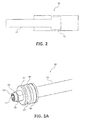
Figure 2 illustrates a schematic view of an actuator in accordance with various embodiments; and -
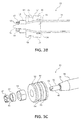
Figures 3A ,3B, and 3C illustrate, respectively, a perspective view, a cross-sectional view, and an exploded view of an actuator in accordance with various embodiments. - The detailed description of exemplary embodiments herein makes reference to the accompanying drawings, which show exemplary embodiments by way of illustration and their best mode. While these exemplary embodiments are described in sufficient detail to enable those skilled in the art to practice the inventions, it should be understood that other embodiments may be realized and that logical and mechanical changes may be made without departing from the scope of the invention. Thus, the detailed description herein is presented for purposes of illustration only and not for limitation. For example, any reference to singular includes plural embodiments, and any reference to more than one component or step may include a singular embodiment or step. Also, any reference to attached, fixed, connected or the like may include permanent, removable, temporary, partial, full and/or any other possible attachment option.
- The present disclosure describes actuators having a composite actuator rod. Such actuators may be used in aircraft systems, such as, for example, landing gear systems. However, the systems and methods of the present disclosure may be suitable for use in non-aircraft systems as well.
- With initial reference to
Figures 1A and 1B , a retraction sequence of alanding gear assembly 10 is illustrated. In various embodiments,landing gear 10 includes astrut 14 supportingwheels 16.Strut 14 is rotatable about a pivot, which is provided by anairframe 12, in response to an extend/retract actuator 18 applying a force to anarm 19. Alinkage 20 may connect a lower portion ofstrut 14 toairframe 12, for example. A lock-stay 22 may be interconnected betweenlinkage 20 andstrut 14 to locklanding gear 10 in a deployed position until landing gear retraction is commanded. - In
Figure 1A ,landing gear 10 is shown in the deployed position. The example lock-stay 22 includes first andsecond links first link 21 is connected tostrut 14 at pivot B. A portion ofsecond link 23 is connected tolinkage 20 at pivot C. Abiasing member 26 is arranged between lock-stay 22 andlinkage 20 to bias lock-stay 22 to the locked position. Anunlock actuator 24 is interconnected betweenlinkage 20 and lock-stay 22 to pull joint D from over-center, as depicted by the arrow inFigure 1B , so that extend/retract actuator 18 can movelanding gear 10 to a stowed position. - With initial reference to
Figure 2 , a schematic diagram ofactuator 30 is illustrated.Actuator 30 may comprise, for example, an extend/retract actuator 18 or an unlock actuator 24 (as illustrated inFigures 1 A and 1B ), or any other type of actuator suitable for use in body-type landing gear systems. Further,actuator 30 may comprise an actuator suitable for use in other systems, including flight control systems, wing and nose landing gear systems, and any other system which utilizes one or more actuators, including non-aircraft systems.Actuator 30 may comprise anactuator body 31 into which an actuator rod tube 33 (also referred to as an actuator piston) retracts and extends.Actuator 30 may comprise, for example an extend/retract actuator 18 or an unlock actuator 24 (as illustrated inFigures 1A and 1B ), or any other type of actuator suitable for use in body-type landing gear systems. Further,actuator 30 may comprise an actuator suitable for use in other systems, including flight control systems, wing and nose landing gear systems, and any other system which utilize one or more actuators, including non-aircraft systems. - In various embodiments, with reference to
Figures 3A-3B ,actuator 30 comprises a compositeactuator rod tube 34. Compositeactuator rod tube 34 may comprise, for example, a lightweight polymer matrix composite such as a carbon fiber composite material or a hydrocarbon fiber composite material. Although composite materials provide reduced weight over traditional metal components, it may be difficult to couple composite materials to metal components. Conventional methods of attaching composite materials to other materials, such as threading or drilling holes in the composite material, may significantly reduce the strength of the composite material. Therefore, methods and apparatus for connecting composite material components (such as composite actuator rod tube 34) to other components (such as metallic components) may be desirable. - Composite
actuator rod tube 34 may comprise atapered end 36. In various embodiments,tapered end 36 is formed of a lightweight polymer matrix composite material. For example,tapered end 36 may comprise the same material as compositeactuator rod tube 34. Taperedend 36 may be configured to provide a tapered surface to engage with a metal component ofactuator 30. As will be discussed in greater detail, a metal component may be secured against and held withintapered end 36, eliminating the need for threading or drilling oftapered end 36 and/oractuator rod tube 34, which would reduce the strength of and/or compromise the structural integrity ofactuator rod tube 34. - Composite
actuator rod tube 34 andtapered end 36 may be formed by laying composite sheets or layers in a desired shape and bonding the layers together using resins, adhesives, or other bonding agents. In further embodiments, compositeactuator rod tube 34 andtapered end 36 may be formed using a fiber-wound form, wherein fiber is continuously wound onto the form and bonded together using resins, adhesives, or other bonding agents. Any manner of forming compositeactuator rod tube 34 andtapered end 36 is within the scope of the present disclosure. - During or after formation,
tapered end 36 may be pretensioned. For example,tapered end 36 may be pretensioned for tensile and/or compressive loads. Such pretensioning may reduce fretting and/or extend the fatigue life oftapered end 36. - In various embodiments, an embedded
bolt 38 is positioned within taperedend 36. Embeddedbolt 38 may comprise a conical bolt having a shape that is complementary totapered end 36. As will be discussed in greater detail, embedded bolt may be positioned within taperedend 36 and held in tension by components located outside ofactuator rod tube 34. In various embodiments, embeddedbolt 38 may be placed within and bonded to taperedend 36 during formation of compositeactuator rod tube 34 and taperedend 36. Embeddedbolt 38 may comprise, for example, a metallic material. However, embeddedbolt 38 may comprise any suitable material. - Embedded
bolt 38 may comprise, for example, a threadedend 40. In various embodiments, threadedend 40 of embeddedbolt 38 extends outward from and beyondtapered end 36 and is configured to receive one or more components capable of holding embeddedbolt 38 in tension withtapered end 36. Embeddedbolt 38 may further comprise aflat segment 42. In various embodiments,flat segment 42 may provide a location to hold stationary as one or more components are engaged to threadedend 40. - In various embodiments, a
piston head 44 may concentrically surround and be secured to embeddedbolt 38. For example,piston head 44 may be positioned concentrically around threadedend 40 and secured by anut 58.Piston head 44 may comprise a metallic material. However,piston head 44 may comprise any suitable material. -
Piston head 44 may comprise aninner profile 60 that is complementary totapered end 36 and/or embeddedbolt 38.Piston head 44 may comprise anouter surface 52 having one ormore seal grooves 54. Further,outer surface 52 may comprise one ormore bearing grooves 56. - In various embodiments, a locking mechanism may be used to assist in securing
nut 58 to embeddedbolt 38. For example, a lockingcup washer 62 may be positioned surrounding threadedend 40 andproximate nut 58. In various embodiments, lockingcup washer 62 may comprise a key 46 configured to engage with aslot 48 of threaded end. Further, ajam nut 50 may be positioned surrounding threadedend 40 and proximatelocking cup washer 62 to secure lockingcup washer 62 to threadedend 40. Other locking mechanisms may also be used to securenut 58, including, for example, a locking tab washer. - Benefits, other advantages, and solutions to problems have been described herein with regard to specific embodiments. Furthermore, the connecting lines shown in the various figures contained herein are intended to represent exemplary functional relationships and/or physical couplings between the various elements. It should be noted that many alternative or additional functional relationships or physical connections may be present in a practical system. However, the benefits, advantages, solutions to problems, and any elements that may cause any benefit, advantage, or solution to occur or become more pronounced are not to be construed as critical, required, or essential features or elements of the inventions. The scope of the inventions is accordingly to be limited by nothing other than the appended claims, in which reference to an element in the singular is not intended to mean "one and only one" unless explicitly so stated, but rather "one or more." Moreover, where a phrase similar to "at least one of A, B, or C" is used in the claims, it is intended that the phrase be interpreted to mean that A alone may be present in an embodiment, B alone may be present in an embodiment, C alone may be present in an embodiment, or that any combination of the elements A, B and C may be present in a single embodiment; for example, A and B, A and C, B and C, or A and B and C. Different cross-hatching is used throughout the figures to denote different parts but not necessarily to denote the same or different materials.
- Systems, methods and apparatus are provided herein. In the detailed description herein, references to "one embodiment," "an embodiment," "an example embodiment," etc., indicate that the embodiment described may include a particular feature, structure, or characteristic, but every embodiment may not necessarily include the particular feature, structure, or characteristic. Moreover, such phrases are not necessarily referring to the same embodiment. Further, when a particular feature, structure, or characteristic is described in connection with an embodiment, it is submitted that it is within the knowledge of one skilled in the art to affect such feature, structure, or characteristic in connection with other embodiments whether or not explicitly described. After reading the description, it will be apparent to one skilled in the relevant art(s) how to implement the disclosure in alternative embodiments.
- Furthermore, the terms "comprises," "comprising," or any other variation thereof, are intended to cover a non-exclusive inclusion, such that a process, method, article, or apparatus that comprises a list of elements does not include only those elements but may include other elements not expressly listed or inherent to such process, method, article, or apparatus.
Claims (15)
- An actuator comprising:a composite actuator rod tube (34) having a tapered end (36);an embedded bolt (38) having a threaded end (40), wherein the embedded bolt has a complementary shape to the tapered end; anda nut (58) configured to engage with the threaded end of the embedded bolt.
- The actuator of claim 1, further comprising a piston head (44) concentrically surrounding the tapered end of the composite actuator rod tube.
- The actuator of claim 1 or 2, further comprising a locking mechanism (64) proximate the nut.
- The actuator of claim 3, wherein the locking mechanism comprises a locking cup washer (62) concentrically surrounding a portion of the threaded end of the embedded bolt and a jam nut (50) engaged with the threaded end of the embedded bolt and proximate the locking cup washer.
- The actuator of claim 4, wherein the locking cup washer comprises a key (46) configured to engage with a slot (48) of the threaded end of the embedded bolt.
- The actuator of claim 2 or any claim dependent thereon, wherein the piston head comprises a sealing groove (54).
- The actuator of any preceding claim, wherein the embedded bolt is bonded to the tapered end of the composite actuator rod tube.
- The actuator of any preceding claim, wherein the threaded end of the embedded bolt comprises a flat segment.
- The actuator of claim 2 or any claim dependent thereon, wherein an outer surface of the piston head comprises a bearing groove (58).
- A method for forming an actuator comprising:forming a composite actuator rod tube having a tapered end concentrically surrounding an embedded bolt having a threaded end and a complementary shape to the tapered end; andbonding the tapered end to the embedded bolt.
- The method of claim 10, wherein the embedded bolt comprises a flat segment.
- The method of claim 11, further comprising concentrically surrounding the tapered end with a piston head and securing the piston head to the tapered end with a nut.
- The method of claim 12, further comprising concentrically surrounding the tapered end with a locking mechanism proximate the nut.
- The method of claim 13, wherein the locking mechanism comprises a locking cup washer concentrically surrounding the threaded end of the embedded bolt and a jam nut proximate the locking cup washer.
- The method of claim 14, wherein the locking cup washer comprises a key configured to engage with a slot of the threaded end of the embedded bolt.
Applications Claiming Priority (1)
| Application Number | Priority Date | Filing Date | Title |
|---|---|---|---|
| US14/609,975 US10190607B2 (en) | 2015-01-30 | 2015-01-30 | Composite actuator piston head assembly |
Publications (2)
| Publication Number | Publication Date |
|---|---|
| EP3051148A1 true EP3051148A1 (en) | 2016-08-03 |
| EP3051148B1 EP3051148B1 (en) | 2019-11-06 |
Family
ID=55299278
Family Applications (1)
| Application Number | Title | Priority Date | Filing Date |
|---|---|---|---|
| EP16153491.2A Active EP3051148B1 (en) | 2015-01-30 | 2016-01-29 | Actuator with a composite piston rod and a metallic piston |
Country Status (2)
| Country | Link |
|---|---|
| US (1) | US10190607B2 (en) |
| EP (1) | EP3051148B1 (en) |
Families Citing this family (7)
| Publication number | Priority date | Publication date | Assignee | Title |
|---|---|---|---|---|
| EP3133298B1 (en) * | 2015-08-21 | 2019-02-06 | Crompton Technology Group Limited | Connector |
| US10066649B2 (en) | 2015-10-13 | 2018-09-04 | Goodrich Corporation | Hybrid metallic/composite piston head joint |
| US10612557B2 (en) * | 2016-07-15 | 2020-04-07 | Rolls-Royce Corporation | Nose cone attachment for turbofan engine |
| US10626917B1 (en) | 2019-04-11 | 2020-04-21 | Goodrich Corporation | Hybrid metallic/composite joint with separate internal bearing |
| US11512738B2 (en) | 2019-04-11 | 2022-11-29 | Goodrich Corporation | Hybrid metallic/composite joint with separate internal bearing |
| FR3111620B1 (en) * | 2020-06-23 | 2022-07-01 | Safran Landing Systems | Undercarriage locking device |
| US11493063B1 (en) | 2022-01-07 | 2022-11-08 | Trelleborg Sealing Solutions Germany Gmbh | Lightweight composite actuator |
Citations (5)
| Publication number | Priority date | Publication date | Assignee | Title |
|---|---|---|---|---|
| JPS611703U (en) * | 1984-06-11 | 1986-01-08 | カヤバ工業株式会社 | hydraulic cylinder |
| JPS63214430A (en) * | 1987-03-03 | 1988-09-07 | Hitachi Constr Mach Co Ltd | Rod body using composite material |
| JPH0626570A (en) * | 1992-03-25 | 1994-02-01 | S T K Shokai:Kk | Hydraulic cylinder |
| JPH0681948A (en) * | 1992-09-07 | 1994-03-22 | Sumitomo Metal Ind Ltd | Cylinder device |
| WO2007139384A1 (en) * | 2006-05-30 | 2007-12-06 | Zumro B.V. | Pressure cylinder with composite piston rod and method for preparing a composite piston rod |
Family Cites Families (3)
| Publication number | Priority date | Publication date | Assignee | Title |
|---|---|---|---|---|
| JPS611703A (en) | 1984-06-12 | 1986-01-07 | 大塚 康弘 | Prevention of snow damage and freezing in cold district |
| US20100247266A1 (en) * | 2009-03-25 | 2010-09-30 | Tadeusz Staniszewski | Self-locking nut |
| DE102014013992A1 (en) * | 2014-09-20 | 2016-03-24 | Festo Ag & Co. Kg | Piston of a fluid-operated linear drive and associated linear drive |
-
2015
- 2015-01-30 US US14/609,975 patent/US10190607B2/en active Active
-
2016
- 2016-01-29 EP EP16153491.2A patent/EP3051148B1/en active Active
Patent Citations (5)
| Publication number | Priority date | Publication date | Assignee | Title |
|---|---|---|---|---|
| JPS611703U (en) * | 1984-06-11 | 1986-01-08 | カヤバ工業株式会社 | hydraulic cylinder |
| JPS63214430A (en) * | 1987-03-03 | 1988-09-07 | Hitachi Constr Mach Co Ltd | Rod body using composite material |
| JPH0626570A (en) * | 1992-03-25 | 1994-02-01 | S T K Shokai:Kk | Hydraulic cylinder |
| JPH0681948A (en) * | 1992-09-07 | 1994-03-22 | Sumitomo Metal Ind Ltd | Cylinder device |
| WO2007139384A1 (en) * | 2006-05-30 | 2007-12-06 | Zumro B.V. | Pressure cylinder with composite piston rod and method for preparing a composite piston rod |
Also Published As
| Publication number | Publication date |
|---|---|
| US20160222993A1 (en) | 2016-08-04 |
| US10190607B2 (en) | 2019-01-29 |
| EP3051148B1 (en) | 2019-11-06 |
Similar Documents
| Publication | Publication Date | Title |
|---|---|---|
| EP3051148B1 (en) | Actuator with a composite piston rod and a metallic piston | |
| US9873506B2 (en) | Composite actuator rod end assembly | |
| US10066649B2 (en) | Hybrid metallic/composite piston head joint | |
| EP2909486B1 (en) | Hybrid joint manufacutring | |
| EP3332946B1 (en) | Composite joint assembly | |
| EP2406071B1 (en) | Composite structures employing quasi-isotropic laminates | |
| EP2952795B1 (en) | Composite tube assembly and method of manufacturing the same | |
| EP2952756B1 (en) | Composite tube assemblies and methods | |
| EP2350469B1 (en) | Joint between aircraft components | |
| EP3381665B1 (en) | Composite structural component with captive mechanical joint | |
| US10935068B2 (en) | Designs and methods of making of joints for composite components under dominant bending load | |
| US12092137B2 (en) | Hybrid metallic/composite joint with enhanced strength | |
| EP2776314B1 (en) | Aircraft structure with means for reducing the risk of disbonding in areas of different strain | |
| EP3306118B1 (en) | Hybrid metallic/composite joint with enhanced performance | |
| EP3260369B1 (en) | Metallic composite joint | |
| US10450087B2 (en) | Lightning strike dispersion for composite aircraft structures | |
| EP3722627B1 (en) | Hybrid metallic/composite joint with integral bearing | |
| EP2943403B1 (en) | Shear pin member intended to join two yokes to form a hinge | |
| CN110901899A (en) | Aircraft landing gear component | |
| US11156245B2 (en) | Hybrid metallic/composite axial tension/compression lobe joint | |
| EP3722621B1 (en) | Hybrid metallic/composite joint with separate internal bearing and coupling flange |
Legal Events
| Date | Code | Title | Description |
|---|---|---|---|
| PUAI | Public reference made under article 153(3) epc to a published international application that has entered the european phase |
Free format text: ORIGINAL CODE: 0009012 |
|
| AK | Designated contracting states |
Kind code of ref document: A1 Designated state(s): AL AT BE BG CH CY CZ DE DK EE ES FI FR GB GR HR HU IE IS IT LI LT LU LV MC MK MT NL NO PL PT RO RS SE SI SK SM TR |
|
| AX | Request for extension of the european patent |
Extension state: BA ME |
|
| RIN1 | Information on inventor provided before grant (corrected) |
Inventor name: GANIS, RONY Inventor name: GOLDRING, ERIC |
|
| STAA | Information on the status of an ep patent application or granted ep patent |
Free format text: STATUS: REQUEST FOR EXAMINATION WAS MADE |
|
| 17P | Request for examination filed |
Effective date: 20170203 |
|
| RBV | Designated contracting states (corrected) |
Designated state(s): AL AT BE BG CH CY CZ DE DK EE ES FI FR GB GR HR HU IE IS IT LI LT LU LV MC MK MT NL NO PL PT RO RS SE SI SK SM TR |
|
| GRAP | Despatch of communication of intention to grant a patent |
Free format text: ORIGINAL CODE: EPIDOSNIGR1 |
|
| STAA | Information on the status of an ep patent application or granted ep patent |
Free format text: STATUS: GRANT OF PATENT IS INTENDED |
|
| INTG | Intention to grant announced |
Effective date: 20190523 |
|
| GRAS | Grant fee paid |
Free format text: ORIGINAL CODE: EPIDOSNIGR3 |
|
| GRAA | (expected) grant |
Free format text: ORIGINAL CODE: 0009210 |
|
| STAA | Information on the status of an ep patent application or granted ep patent |
Free format text: STATUS: THE PATENT HAS BEEN GRANTED |
|
| AK | Designated contracting states |
Kind code of ref document: B1 Designated state(s): AL AT BE BG CH CY CZ DE DK EE ES FI FR GB GR HR HU IE IS IT LI LT LU LV MC MK MT NL NO PL PT RO RS SE SI SK SM TR |
|
| REG | Reference to a national code |
Ref country code: GB Ref legal event code: FG4D |
|
| REG | Reference to a national code |
Ref country code: CH Ref legal event code: EP Ref country code: AT Ref legal event code: REF Ref document number: 1199080 Country of ref document: AT Kind code of ref document: T Effective date: 20191115 |
|
| REG | Reference to a national code |
Ref country code: DE Ref legal event code: R096 Ref document number: 602016023569 Country of ref document: DE |
|
| REG | Reference to a national code |
Ref country code: IE Ref legal event code: FG4D |
|
| REG | Reference to a national code |
Ref country code: NL Ref legal event code: MP Effective date: 20191106 |
|
| REG | Reference to a national code |
Ref country code: LT Ref legal event code: MG4D |
|
| PG25 | Lapsed in a contracting state [announced via postgrant information from national office to epo] |
Ref country code: PT Free format text: LAPSE BECAUSE OF FAILURE TO SUBMIT A TRANSLATION OF THE DESCRIPTION OR TO PAY THE FEE WITHIN THE PRESCRIBED TIME-LIMIT Effective date: 20200306 Ref country code: NL Free format text: LAPSE BECAUSE OF FAILURE TO SUBMIT A TRANSLATION OF THE DESCRIPTION OR TO PAY THE FEE WITHIN THE PRESCRIBED TIME-LIMIT Effective date: 20191106 Ref country code: LT Free format text: LAPSE BECAUSE OF FAILURE TO SUBMIT A TRANSLATION OF THE DESCRIPTION OR TO PAY THE FEE WITHIN THE PRESCRIBED TIME-LIMIT Effective date: 20191106 Ref country code: PL Free format text: LAPSE BECAUSE OF FAILURE TO SUBMIT A TRANSLATION OF THE DESCRIPTION OR TO PAY THE FEE WITHIN THE PRESCRIBED TIME-LIMIT Effective date: 20191106 Ref country code: GR Free format text: LAPSE BECAUSE OF FAILURE TO SUBMIT A TRANSLATION OF THE DESCRIPTION OR TO PAY THE FEE WITHIN THE PRESCRIBED TIME-LIMIT Effective date: 20200207 Ref country code: SE Free format text: LAPSE BECAUSE OF FAILURE TO SUBMIT A TRANSLATION OF THE DESCRIPTION OR TO PAY THE FEE WITHIN THE PRESCRIBED TIME-LIMIT Effective date: 20191106 Ref country code: NO Free format text: LAPSE BECAUSE OF FAILURE TO SUBMIT A TRANSLATION OF THE DESCRIPTION OR TO PAY THE FEE WITHIN THE PRESCRIBED TIME-LIMIT Effective date: 20200206 Ref country code: LV Free format text: LAPSE BECAUSE OF FAILURE TO SUBMIT A TRANSLATION OF THE DESCRIPTION OR TO PAY THE FEE WITHIN THE PRESCRIBED TIME-LIMIT Effective date: 20191106 Ref country code: FI Free format text: LAPSE BECAUSE OF FAILURE TO SUBMIT A TRANSLATION OF THE DESCRIPTION OR TO PAY THE FEE WITHIN THE PRESCRIBED TIME-LIMIT Effective date: 20191106 Ref country code: BG Free format text: LAPSE BECAUSE OF FAILURE TO SUBMIT A TRANSLATION OF THE DESCRIPTION OR TO PAY THE FEE WITHIN THE PRESCRIBED TIME-LIMIT Effective date: 20200206 |
|
| PG25 | Lapsed in a contracting state [announced via postgrant information from national office to epo] |
Ref country code: RS Free format text: LAPSE BECAUSE OF FAILURE TO SUBMIT A TRANSLATION OF THE DESCRIPTION OR TO PAY THE FEE WITHIN THE PRESCRIBED TIME-LIMIT Effective date: 20191106 Ref country code: IS Free format text: LAPSE BECAUSE OF FAILURE TO SUBMIT A TRANSLATION OF THE DESCRIPTION OR TO PAY THE FEE WITHIN THE PRESCRIBED TIME-LIMIT Effective date: 20200306 Ref country code: HR Free format text: LAPSE BECAUSE OF FAILURE TO SUBMIT A TRANSLATION OF THE DESCRIPTION OR TO PAY THE FEE WITHIN THE PRESCRIBED TIME-LIMIT Effective date: 20191106 |
|
| PG25 | Lapsed in a contracting state [announced via postgrant information from national office to epo] |
Ref country code: AL Free format text: LAPSE BECAUSE OF FAILURE TO SUBMIT A TRANSLATION OF THE DESCRIPTION OR TO PAY THE FEE WITHIN THE PRESCRIBED TIME-LIMIT Effective date: 20191106 |
|
| PG25 | Lapsed in a contracting state [announced via postgrant information from national office to epo] |
Ref country code: EE Free format text: LAPSE BECAUSE OF FAILURE TO SUBMIT A TRANSLATION OF THE DESCRIPTION OR TO PAY THE FEE WITHIN THE PRESCRIBED TIME-LIMIT Effective date: 20191106 Ref country code: DK Free format text: LAPSE BECAUSE OF FAILURE TO SUBMIT A TRANSLATION OF THE DESCRIPTION OR TO PAY THE FEE WITHIN THE PRESCRIBED TIME-LIMIT Effective date: 20191106 Ref country code: ES Free format text: LAPSE BECAUSE OF FAILURE TO SUBMIT A TRANSLATION OF THE DESCRIPTION OR TO PAY THE FEE WITHIN THE PRESCRIBED TIME-LIMIT Effective date: 20191106 Ref country code: CZ Free format text: LAPSE BECAUSE OF FAILURE TO SUBMIT A TRANSLATION OF THE DESCRIPTION OR TO PAY THE FEE WITHIN THE PRESCRIBED TIME-LIMIT Effective date: 20191106 Ref country code: RO Free format text: LAPSE BECAUSE OF FAILURE TO SUBMIT A TRANSLATION OF THE DESCRIPTION OR TO PAY THE FEE WITHIN THE PRESCRIBED TIME-LIMIT Effective date: 20191106 |
|
| REG | Reference to a national code |
Ref country code: DE Ref legal event code: R097 Ref document number: 602016023569 Country of ref document: DE |
|
| REG | Reference to a national code |
Ref country code: AT Ref legal event code: MK05 Ref document number: 1199080 Country of ref document: AT Kind code of ref document: T Effective date: 20191106 |
|
| PG25 | Lapsed in a contracting state [announced via postgrant information from national office to epo] |
Ref country code: SM Free format text: LAPSE BECAUSE OF FAILURE TO SUBMIT A TRANSLATION OF THE DESCRIPTION OR TO PAY THE FEE WITHIN THE PRESCRIBED TIME-LIMIT Effective date: 20191106 Ref country code: MC Free format text: LAPSE BECAUSE OF FAILURE TO SUBMIT A TRANSLATION OF THE DESCRIPTION OR TO PAY THE FEE WITHIN THE PRESCRIBED TIME-LIMIT Effective date: 20191106 Ref country code: SK Free format text: LAPSE BECAUSE OF FAILURE TO SUBMIT A TRANSLATION OF THE DESCRIPTION OR TO PAY THE FEE WITHIN THE PRESCRIBED TIME-LIMIT Effective date: 20191106 |
|
| REG | Reference to a national code |
Ref country code: CH Ref legal event code: PL |
|
| PLBE | No opposition filed within time limit |
Free format text: ORIGINAL CODE: 0009261 |
|
| STAA | Information on the status of an ep patent application or granted ep patent |
Free format text: STATUS: NO OPPOSITION FILED WITHIN TIME LIMIT |
|
| 26N | No opposition filed |
Effective date: 20200807 |
|
| REG | Reference to a national code |
Ref country code: BE Ref legal event code: MM Effective date: 20200131 |
|
| PG25 | Lapsed in a contracting state [announced via postgrant information from national office to epo] |
Ref country code: FR Free format text: LAPSE BECAUSE OF NON-PAYMENT OF DUE FEES Effective date: 20200131 Ref country code: LU Free format text: LAPSE BECAUSE OF NON-PAYMENT OF DUE FEES Effective date: 20200129 |
|
| PG25 | Lapsed in a contracting state [announced via postgrant information from national office to epo] |
Ref country code: LI Free format text: LAPSE BECAUSE OF NON-PAYMENT OF DUE FEES Effective date: 20200131 Ref country code: SI Free format text: LAPSE BECAUSE OF FAILURE TO SUBMIT A TRANSLATION OF THE DESCRIPTION OR TO PAY THE FEE WITHIN THE PRESCRIBED TIME-LIMIT Effective date: 20191106 Ref country code: BE Free format text: LAPSE BECAUSE OF NON-PAYMENT OF DUE FEES Effective date: 20200131 Ref country code: CH Free format text: LAPSE BECAUSE OF NON-PAYMENT OF DUE FEES Effective date: 20200131 Ref country code: AT Free format text: LAPSE BECAUSE OF FAILURE TO SUBMIT A TRANSLATION OF THE DESCRIPTION OR TO PAY THE FEE WITHIN THE PRESCRIBED TIME-LIMIT Effective date: 20191106 |
|
| PG25 | Lapsed in a contracting state [announced via postgrant information from national office to epo] |
Ref country code: IT Free format text: LAPSE BECAUSE OF FAILURE TO SUBMIT A TRANSLATION OF THE DESCRIPTION OR TO PAY THE FEE WITHIN THE PRESCRIBED TIME-LIMIT Effective date: 20191106 Ref country code: IE Free format text: LAPSE BECAUSE OF NON-PAYMENT OF DUE FEES Effective date: 20200129 |
|
| PG25 | Lapsed in a contracting state [announced via postgrant information from national office to epo] |
Ref country code: TR Free format text: LAPSE BECAUSE OF FAILURE TO SUBMIT A TRANSLATION OF THE DESCRIPTION OR TO PAY THE FEE WITHIN THE PRESCRIBED TIME-LIMIT Effective date: 20191106 Ref country code: MT Free format text: LAPSE BECAUSE OF FAILURE TO SUBMIT A TRANSLATION OF THE DESCRIPTION OR TO PAY THE FEE WITHIN THE PRESCRIBED TIME-LIMIT Effective date: 20191106 Ref country code: CY Free format text: LAPSE BECAUSE OF FAILURE TO SUBMIT A TRANSLATION OF THE DESCRIPTION OR TO PAY THE FEE WITHIN THE PRESCRIBED TIME-LIMIT Effective date: 20191106 |
|
| PG25 | Lapsed in a contracting state [announced via postgrant information from national office to epo] |
Ref country code: MK Free format text: LAPSE BECAUSE OF FAILURE TO SUBMIT A TRANSLATION OF THE DESCRIPTION OR TO PAY THE FEE WITHIN THE PRESCRIBED TIME-LIMIT Effective date: 20191106 |
|
| P01 | Opt-out of the competence of the unified patent court (upc) registered |
Effective date: 20230522 |
|
| PGFP | Annual fee paid to national office [announced via postgrant information from national office to epo] |
Ref country code: GB Payment date: 20251220 Year of fee payment: 11 |
|
| PGFP | Annual fee paid to national office [announced via postgrant information from national office to epo] |
Ref country code: DE Payment date: 20251217 Year of fee payment: 11 |