EP3050997A1 - Method for diffusion coating heat-resistant metal member with creep reinforcement material, and creep-strength-enhanced heat-resistant metal member - Google Patents
Method for diffusion coating heat-resistant metal member with creep reinforcement material, and creep-strength-enhanced heat-resistant metal member Download PDFInfo
- Publication number
- EP3050997A1 EP3050997A1 EP13894771.8A EP13894771A EP3050997A1 EP 3050997 A1 EP3050997 A1 EP 3050997A1 EP 13894771 A EP13894771 A EP 13894771A EP 3050997 A1 EP3050997 A1 EP 3050997A1
- Authority
- EP
- European Patent Office
- Prior art keywords
- heat
- resistant metal
- metal member
- resistant
- creep
- Prior art date
- Legal status (The legal status is an assumption and is not a legal conclusion. Google has not performed a legal analysis and makes no representation as to the accuracy of the status listed.)
- Granted
Links
Images
Classifications
-
- C—CHEMISTRY; METALLURGY
- C23—COATING METALLIC MATERIAL; COATING MATERIAL WITH METALLIC MATERIAL; CHEMICAL SURFACE TREATMENT; DIFFUSION TREATMENT OF METALLIC MATERIAL; COATING BY VACUUM EVAPORATION, BY SPUTTERING, BY ION IMPLANTATION OR BY CHEMICAL VAPOUR DEPOSITION, IN GENERAL; INHIBITING CORROSION OF METALLIC MATERIAL OR INCRUSTATION IN GENERAL
- C23C—COATING METALLIC MATERIAL; COATING MATERIAL WITH METALLIC MATERIAL; SURFACE TREATMENT OF METALLIC MATERIAL BY DIFFUSION INTO THE SURFACE, BY CHEMICAL CONVERSION OR SUBSTITUTION; COATING BY VACUUM EVAPORATION, BY SPUTTERING, BY ION IMPLANTATION OR BY CHEMICAL VAPOUR DEPOSITION, IN GENERAL
- C23C4/00—Coating by spraying the coating material in the molten state, e.g. by flame, plasma or electric discharge
- C23C4/12—Coating by spraying the coating material in the molten state, e.g. by flame, plasma or electric discharge characterised by the method of spraying
-
- C—CHEMISTRY; METALLURGY
- C23—COATING METALLIC MATERIAL; COATING MATERIAL WITH METALLIC MATERIAL; CHEMICAL SURFACE TREATMENT; DIFFUSION TREATMENT OF METALLIC MATERIAL; COATING BY VACUUM EVAPORATION, BY SPUTTERING, BY ION IMPLANTATION OR BY CHEMICAL VAPOUR DEPOSITION, IN GENERAL; INHIBITING CORROSION OF METALLIC MATERIAL OR INCRUSTATION IN GENERAL
- C23C—COATING METALLIC MATERIAL; COATING MATERIAL WITH METALLIC MATERIAL; SURFACE TREATMENT OF METALLIC MATERIAL BY DIFFUSION INTO THE SURFACE, BY CHEMICAL CONVERSION OR SUBSTITUTION; COATING BY VACUUM EVAPORATION, BY SPUTTERING, BY ION IMPLANTATION OR BY CHEMICAL VAPOUR DEPOSITION, IN GENERAL
- C23C4/00—Coating by spraying the coating material in the molten state, e.g. by flame, plasma or electric discharge
- C23C4/04—Coating by spraying the coating material in the molten state, e.g. by flame, plasma or electric discharge characterised by the coating material
- C23C4/06—Metallic material
-
- C—CHEMISTRY; METALLURGY
- C23—COATING METALLIC MATERIAL; COATING MATERIAL WITH METALLIC MATERIAL; CHEMICAL SURFACE TREATMENT; DIFFUSION TREATMENT OF METALLIC MATERIAL; COATING BY VACUUM EVAPORATION, BY SPUTTERING, BY ION IMPLANTATION OR BY CHEMICAL VAPOUR DEPOSITION, IN GENERAL; INHIBITING CORROSION OF METALLIC MATERIAL OR INCRUSTATION IN GENERAL
- C23C—COATING METALLIC MATERIAL; COATING MATERIAL WITH METALLIC MATERIAL; SURFACE TREATMENT OF METALLIC MATERIAL BY DIFFUSION INTO THE SURFACE, BY CHEMICAL CONVERSION OR SUBSTITUTION; COATING BY VACUUM EVAPORATION, BY SPUTTERING, BY ION IMPLANTATION OR BY CHEMICAL VAPOUR DEPOSITION, IN GENERAL
- C23C4/00—Coating by spraying the coating material in the molten state, e.g. by flame, plasma or electric discharge
- C23C4/04—Coating by spraying the coating material in the molten state, e.g. by flame, plasma or electric discharge characterised by the coating material
- C23C4/10—Oxides, borides, carbides, nitrides or silicides; Mixtures thereof
-
- C—CHEMISTRY; METALLURGY
- C23—COATING METALLIC MATERIAL; COATING MATERIAL WITH METALLIC MATERIAL; CHEMICAL SURFACE TREATMENT; DIFFUSION TREATMENT OF METALLIC MATERIAL; COATING BY VACUUM EVAPORATION, BY SPUTTERING, BY ION IMPLANTATION OR BY CHEMICAL VAPOUR DEPOSITION, IN GENERAL; INHIBITING CORROSION OF METALLIC MATERIAL OR INCRUSTATION IN GENERAL
- C23C—COATING METALLIC MATERIAL; COATING MATERIAL WITH METALLIC MATERIAL; SURFACE TREATMENT OF METALLIC MATERIAL BY DIFFUSION INTO THE SURFACE, BY CHEMICAL CONVERSION OR SUBSTITUTION; COATING BY VACUUM EVAPORATION, BY SPUTTERING, BY ION IMPLANTATION OR BY CHEMICAL VAPOUR DEPOSITION, IN GENERAL
- C23C4/00—Coating by spraying the coating material in the molten state, e.g. by flame, plasma or electric discharge
- C23C4/04—Coating by spraying the coating material in the molten state, e.g. by flame, plasma or electric discharge characterised by the coating material
- C23C4/10—Oxides, borides, carbides, nitrides or silicides; Mixtures thereof
- C23C4/11—Oxides
-
- C—CHEMISTRY; METALLURGY
- C23—COATING METALLIC MATERIAL; COATING MATERIAL WITH METALLIC MATERIAL; CHEMICAL SURFACE TREATMENT; DIFFUSION TREATMENT OF METALLIC MATERIAL; COATING BY VACUUM EVAPORATION, BY SPUTTERING, BY ION IMPLANTATION OR BY CHEMICAL VAPOUR DEPOSITION, IN GENERAL; INHIBITING CORROSION OF METALLIC MATERIAL OR INCRUSTATION IN GENERAL
- C23C—COATING METALLIC MATERIAL; COATING MATERIAL WITH METALLIC MATERIAL; SURFACE TREATMENT OF METALLIC MATERIAL BY DIFFUSION INTO THE SURFACE, BY CHEMICAL CONVERSION OR SUBSTITUTION; COATING BY VACUUM EVAPORATION, BY SPUTTERING, BY ION IMPLANTATION OR BY CHEMICAL VAPOUR DEPOSITION, IN GENERAL
- C23C4/00—Coating by spraying the coating material in the molten state, e.g. by flame, plasma or electric discharge
- C23C4/12—Coating by spraying the coating material in the molten state, e.g. by flame, plasma or electric discharge characterised by the method of spraying
- C23C4/14—Coating by spraying the coating material in the molten state, e.g. by flame, plasma or electric discharge characterised by the method of spraying for coating elongate material
- C23C4/16—Wires; Tubes
-
- C—CHEMISTRY; METALLURGY
- C23—COATING METALLIC MATERIAL; COATING MATERIAL WITH METALLIC MATERIAL; CHEMICAL SURFACE TREATMENT; DIFFUSION TREATMENT OF METALLIC MATERIAL; COATING BY VACUUM EVAPORATION, BY SPUTTERING, BY ION IMPLANTATION OR BY CHEMICAL VAPOUR DEPOSITION, IN GENERAL; INHIBITING CORROSION OF METALLIC MATERIAL OR INCRUSTATION IN GENERAL
- C23C—COATING METALLIC MATERIAL; COATING MATERIAL WITH METALLIC MATERIAL; SURFACE TREATMENT OF METALLIC MATERIAL BY DIFFUSION INTO THE SURFACE, BY CHEMICAL CONVERSION OR SUBSTITUTION; COATING BY VACUUM EVAPORATION, BY SPUTTERING, BY ION IMPLANTATION OR BY CHEMICAL VAPOUR DEPOSITION, IN GENERAL
- C23C4/00—Coating by spraying the coating material in the molten state, e.g. by flame, plasma or electric discharge
- C23C4/18—After-treatment
-
- C—CHEMISTRY; METALLURGY
- C21—METALLURGY OF IRON
- C21D—MODIFYING THE PHYSICAL STRUCTURE OF FERROUS METALS; GENERAL DEVICES FOR HEAT TREATMENT OF FERROUS OR NON-FERROUS METALS OR ALLOYS; MAKING METAL MALLEABLE, e.g. BY DECARBURISATION OR TEMPERING
- C21D2251/00—Treating composite or clad material
-
- C—CHEMISTRY; METALLURGY
- C21—METALLURGY OF IRON
- C21D—MODIFYING THE PHYSICAL STRUCTURE OF FERROUS METALS; GENERAL DEVICES FOR HEAT TREATMENT OF FERROUS OR NON-FERROUS METALS OR ALLOYS; MAKING METAL MALLEABLE, e.g. BY DECARBURISATION OR TEMPERING
- C21D9/00—Heat treatment, e.g. annealing, hardening, quenching or tempering, adapted for particular articles; Furnaces therefor
- C21D9/08—Heat treatment, e.g. annealing, hardening, quenching or tempering, adapted for particular articles; Furnaces therefor for tubular bodies or pipes
-
- C—CHEMISTRY; METALLURGY
- C21—METALLURGY OF IRON
- C21D—MODIFYING THE PHYSICAL STRUCTURE OF FERROUS METALS; GENERAL DEVICES FOR HEAT TREATMENT OF FERROUS OR NON-FERROUS METALS OR ALLOYS; MAKING METAL MALLEABLE, e.g. BY DECARBURISATION OR TEMPERING
- C21D9/00—Heat treatment, e.g. annealing, hardening, quenching or tempering, adapted for particular articles; Furnaces therefor
- C21D9/50—Heat treatment, e.g. annealing, hardening, quenching or tempering, adapted for particular articles; Furnaces therefor for welded joints
-
- Y—GENERAL TAGGING OF NEW TECHNOLOGICAL DEVELOPMENTS; GENERAL TAGGING OF CROSS-SECTIONAL TECHNOLOGIES SPANNING OVER SEVERAL SECTIONS OF THE IPC; TECHNICAL SUBJECTS COVERED BY FORMER USPC CROSS-REFERENCE ART COLLECTIONS [XRACs] AND DIGESTS
- Y10—TECHNICAL SUBJECTS COVERED BY FORMER USPC
- Y10T—TECHNICAL SUBJECTS COVERED BY FORMER US CLASSIFICATION
- Y10T428/00—Stock material or miscellaneous articles
- Y10T428/12—All metal or with adjacent metals
- Y10T428/12493—Composite; i.e., plural, adjacent, spatially distinct metal components [e.g., layers, joint, etc.]
- Y10T428/12535—Composite; i.e., plural, adjacent, spatially distinct metal components [e.g., layers, joint, etc.] with additional, spatially distinct nonmetal component
- Y10T428/12576—Boride, carbide or nitride component
-
- Y—GENERAL TAGGING OF NEW TECHNOLOGICAL DEVELOPMENTS; GENERAL TAGGING OF CROSS-SECTIONAL TECHNOLOGIES SPANNING OVER SEVERAL SECTIONS OF THE IPC; TECHNICAL SUBJECTS COVERED BY FORMER USPC CROSS-REFERENCE ART COLLECTIONS [XRACs] AND DIGESTS
- Y10—TECHNICAL SUBJECTS COVERED BY FORMER USPC
- Y10T—TECHNICAL SUBJECTS COVERED BY FORMER US CLASSIFICATION
- Y10T428/00—Stock material or miscellaneous articles
- Y10T428/12—All metal or with adjacent metals
- Y10T428/12493—Composite; i.e., plural, adjacent, spatially distinct metal components [e.g., layers, joint, etc.]
- Y10T428/12535—Composite; i.e., plural, adjacent, spatially distinct metal components [e.g., layers, joint, etc.] with additional, spatially distinct nonmetal component
- Y10T428/12583—Component contains compound of adjacent metal
-
- Y—GENERAL TAGGING OF NEW TECHNOLOGICAL DEVELOPMENTS; GENERAL TAGGING OF CROSS-SECTIONAL TECHNOLOGIES SPANNING OVER SEVERAL SECTIONS OF THE IPC; TECHNICAL SUBJECTS COVERED BY FORMER USPC CROSS-REFERENCE ART COLLECTIONS [XRACs] AND DIGESTS
- Y10—TECHNICAL SUBJECTS COVERED BY FORMER USPC
- Y10T—TECHNICAL SUBJECTS COVERED BY FORMER US CLASSIFICATION
- Y10T428/00—Stock material or miscellaneous articles
- Y10T428/12—All metal or with adjacent metals
- Y10T428/12493—Composite; i.e., plural, adjacent, spatially distinct metal components [e.g., layers, joint, etc.]
- Y10T428/12535—Composite; i.e., plural, adjacent, spatially distinct metal components [e.g., layers, joint, etc.] with additional, spatially distinct nonmetal component
- Y10T428/12583—Component contains compound of adjacent metal
- Y10T428/1259—Oxide
-
- Y—GENERAL TAGGING OF NEW TECHNOLOGICAL DEVELOPMENTS; GENERAL TAGGING OF CROSS-SECTIONAL TECHNOLOGIES SPANNING OVER SEVERAL SECTIONS OF THE IPC; TECHNICAL SUBJECTS COVERED BY FORMER USPC CROSS-REFERENCE ART COLLECTIONS [XRACs] AND DIGESTS
- Y10—TECHNICAL SUBJECTS COVERED BY FORMER USPC
- Y10T—TECHNICAL SUBJECTS COVERED BY FORMER US CLASSIFICATION
- Y10T428/00—Stock material or miscellaneous articles
- Y10T428/12—All metal or with adjacent metals
- Y10T428/12493—Composite; i.e., plural, adjacent, spatially distinct metal components [e.g., layers, joint, etc.]
- Y10T428/12771—Transition metal-base component
- Y10T428/12861—Group VIII or IB metal-base component
- Y10T428/12931—Co-, Fe-, or Ni-base components, alternative to each other
Definitions
- the present invention relates to a method for diffusing and permeating a creep reinforcement material into a heat-resistant metal member, and to a heat-resistant metal member with creep strength enhanced by such a method.
- An object of the present invention is to provide a method capable of efficiently diffusing and permeating a material that enhances creep strength (hereinafter referred to as a "creep reinforcement material") into a member manufactured using a heat-resistant metal material (hereinafter referred to as a "heat-resistant metal member”), and to provide a heat-resistant metal member with creep strength enhanced by such a method.
- a method for diffusing and permeating a creep reinforcement material into a heat-resistant metal member, and a heat-resistant metal member with creep strength enhanced by such a method include the following configuration. More specifically, the present invention includes:
- the present invention enables provision of a method capable of efficiently diffusing and permeating a creep reinforcement material into a heat-resistant metal member, and provision of a heat-resistant metal member with creep strength enhanced by such a method.
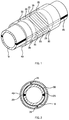
- Fig. 1 is a schematic diagram illustrating a method for diffusing and permeating a creep reinforcement material into a heat-resistant metal member, to explain an embodiment of the present invention.
- Fig. 2 is a schematic cross-section illustrating a cross-section of Fig. 1 , to explain an embodiment of the present invention.
- explanation is of an example of a case in which an already installed (including repaired cases thereof) or unused, or a degraded, high temperature pipe manufactured using a heat-resistant metal material, is employed as a heat-resistant metal member 10, however, there is no limitation thereto.
- the heat-resistant metal member 10 may be another high temperature member manufactured using a heat-resistant metal material, such as an already installed (including repaired cases thereof) or unused, or a degraded, turbine.
- the creep reinforcement material is coated or thermally sprayed onto a surface of the heat-resistant metal member 10. Then a section 25 onto which the creep reinforcement material has been coated or thermally sprayed is covered by a heat-resistant covering member 30, and the heat-resistant covering member 30 is secured so as to make contact with the section 25. Next, the heat-resistant metal member 10 covered by the heat-resistant covering member 30 is heated for a specific duration at a temperature of 1000°C or greater using a heater 40.
- the heat-resistant metal member 10 coated or thermally sprayed with the creep reinforcement material is covered by the heat-resistant covering member 30 and is heated to a temperature of 1000°C or greater, and thus compressive force acts on the heat-resistant metal member as it thermally expands in a direction toward an outer periphery, restraining thermal expansion of the heat-resistant metal member in the direction toward the outer periphery, and enabling the creep reinforcement material on the surface of the heat-resistant metal member 10 to be efficiently diffused and permeated into the heat-resistant metal member 10.
- the heat-resistant metal member 10 is a degraded member or an already installed member
- creep voids and cracks in the heat-resistant metal member 10 and a weld 20 thereof are efficiently repaired, enabling regeneration of the heat-resistant metal member 10 and the weld 20 thereof to be achieved.
- structural strengthening of the heat-resistant metal member 10 and the weld 20 thereof can be achieved accompanying restoration of the structure of the heat-resistant metal member 10 and the weld 20 thereof.
- the creep strength is accordingly enhanced, enabling the lifespan to be extended to that of a new member or greater.
- etching treatment or shot peening and etching treatment, may be performed on the section 25 to be coated or thermally sprayed with the creep reinforcement material prior to coating or thermally spraying the creep reinforcement material on the surface of the heat-resistant metal member 10.
- Such processing enables work hardening of the surface layer of the heat-resistant metal member 10 to be performed by plastic deformation, enables residual compressive stress to be imparted to the surface of the heat-resistant metal member 10, and enables any oxidized film on the surface of the heat-resistant metal member 10 to be removed.
- processing to remove (reduce) residual stress may be performed after the heat-resistant metal member 10 covered by the heat-resistant covering member 30 has been heated to a temperature of 1000°C or greater using the heater 40.
- the heat-resistant metal member 10 may be first cooled to room temperature, then reheated to a temperature of an A 1 transformation point or greater (preferably from 10°C to 100°C above 1000°C) for a specific duration (for example, from approximately several hours to approximately 24 hours).
- the heat-resistant metal member 10 in order to restrict thermal expansion of the heat-resistant metal member 10 toward the outside in the length direction thereof (in directions toward the ends of the heat-resistant metal member 10) occurring when the heat-resistant metal member 10, which has been coated or thermally sprayed with the creep reinforcement material, is covered by the heat-resistant covering member 30 and heated by the heater 40, the heat-resistant metal member 10 may be secured in sections not being heated by the heater 40, by, for example, two clamps so as to sandwich the section being heated by the heater 40.
- Examples of the heat-resistant metal of the member 10 include 0.3Mo steel, 0.5Mo steel, 0.5Cr-0.5Mo steel, 1Cr-0.2Mo steel, 1Cr-0.5Mo steel, 1.25Cr-0.5Mo steel, 2.25Cr-1Mo steel, 5Cr-0.5Mo steel, 7Cr-0.5Mo steel, 9Cr-1Mo steel, 0.3Cr-Mo-V steel, 0.5Cr-Mo-V steel, 9Cr-Mo-V steel, 12Cr-Mo-V steel, 1Cr-1.25Mo-0.25V steel, 9Cr-1Mo-W steel, SUS304, SUS304L, SUS316, SUS316L, SUS316TI, SUS317, SUS321, SUS347H, SUS310S, Super304, SUS904L, NCF600, NCF601, NCF800, and NCF800H; however, there is no limitation thereto. Any known material used for members employed in thermal or nuclear power
- the creep reinforcement material may contain any one or a plurality of elements appropriately selected from B (boron), W (tungsten), Cr (Chromium), Mo (molybdenum), Nb (niobium), V (vanadium), Hf (hafnium), Zr (zirconium), Ti (titanium), Cu (copper), and Co (cobalt).
- the creep reinforcement material is coated on the surface of the heat-resistant metal member 10
- powdered creep reinforcement material may be employed as it is, or a coating agent of the creep reinforcement material in a liquid form or paste form using a binder, solvent, adhesive or the like may be employed.
- a known thermal spray method may be appropriately employed, such as a plasma spraying method using powdered creep reinforcement material. Note that coating or thermally spraying of the creep reinforcement material on the surface of the heat-resistant metal member 10 may be performed over the entire outer peripheral surface of the heat-resistant metal member 10 as in the present embodiment, or may be performed on a part of the surface of the heat-resistant metal member 10.
- the heat-resistant covering member 30 there are no particular limitations to the heat-resistant covering member 30, as long as it is capable of covering the section 25 coated or thermally sprayed with the creep reinforcement material so as to make contact with the section 25, as long as it is made from a heat-resistant material that restrains thermal expansion in the section 25 in the direction toward the outer periphery of the heat-resistant metal member 10 occurring when heated to the heating temperature mentioned above, and is able to maintain the approximate profile of the heat-resistant metal member 10 at the section 25.
- a material having a lower thermal expansion coefficient than the heat-resistant metal member 10 at temperatures of the heating temperature mentioned above or greater is preferably employed for the heat-resistant covering member 30.
- the heat-resistant covering member 30 is configured from a heat-resistant material different from that of the heat-resistant metal member 10, yet having a thermal expansion coefficient of about the same as the heat-resistant metal member 10, or from a heat resistant material having a higher thermal expansion coefficient than the heat-resistant metal member 10, in order to restrain the thermal expansion of the heat-resistant covering member 30 occurring when heated to the heating temperature mentioned above, the outer periphery of the heat-resistant covering member 30 may be secured by a member of a heat-resistant material having a lower thermal expansion coefficient than the heat-resistant metal member 10 at or above the heating temperature mentioned above, so as to maintain the profile of the heat-resistant covering member 30.
- heat-resistant material of the heat-resistant covering member 30 examples include ceramics such as alumina, zirconia, aluminum nitride, silicon carbide, silicon nitride, cordierite, sialon, zircon, and mullite, and alloys such as Alloy 903, Alloy 909, and HRA 929.
- the heat-resistant covering member 30 is, for example, of a cord, plate, or clamp shape. Securing of the above may be performed by, for example, wrapping a cord-shaped or plate-shaped heat-resistant covering member 30 around the outer periphery of the heat-resistant metal member 10 at the section 25 coated or thermally sprayed with the creep reinforcement material, by attaching a clamp-shaped heat-resistant covering member 30 to the outer periphery of the heat-resistant metal member 10 at the section 25 coated or thermally sprayed with the creep reinforcement material, or by attaching a heat-resistant covering member 30 formed in a plate shape or the like to the outer periphery of a heat-resistant metal member 10 at the section 25 coated or thermally sprayed with the creep reinforcement material using fasteners, such as clamps or screws.
- the heat-resistant covering member 30 is made from fittings including two substantially semi-circular arc cross-section shapes.
- the heat-resistant covering member 30 is then secured to the surface of the heat-resistant metal member 10 using threaded members 35 attached to flanges of these fittings, such that the inner face of the fittings contact the outer periphery of the heat-resistant metal member 10 at the section 25 coated or thermally sprayed with the creep reinforcement material.
- the threaded members 35 are manufactured, for example, from the same material as the heat-resistant covering member 30.
- the heating temperature of the heat-resistant metal member 10 coated or thermally sprayed with the creep reinforcement material is not particularly limited, as long as it is a temperature of 1000°C or greater.
- the heat-resistant metal member 10 is heated at a temperature of, or greater than, an A 3 transformation point of the component of the heat-resistant metal material of the member 10 or the creep reinforcement material having the highest A 3 transformation point (preferably from 10°C to 100°C above 1000°C) for a specific duration (for example, from approximately several hours to approximately 24 hours).
- the present embodiment employs, as a heating device, the high frequency heater 40, which is capable of heating the heat-resistant metal member 10 coated or thermally sprayed with the creep reinforcement material, from the outer periphery thereof, there is no particular limitation thereto, as long as a heating device capable of heating the heat-resistant metal member 10 at the section 25 coated or thermally sprayed with the creep reinforcement material.
- the product of diffusing and permeating the creep reinforcement material into the heat-resistant metal member 10 by the method described above is useful as a heat-resistant metal member with enhanced creep strength due to the creep strength being enhanced as described above.
Landscapes
- Chemical & Material Sciences (AREA)
- Engineering & Computer Science (AREA)
- Mechanical Engineering (AREA)
- Materials Engineering (AREA)
- Metallurgy (AREA)
- Organic Chemistry (AREA)
- Chemical Kinetics & Catalysis (AREA)
- Physics & Mathematics (AREA)
- Plasma & Fusion (AREA)
- Coating By Spraying Or Casting (AREA)
- Thermal Sciences (AREA)
- Crystallography & Structural Chemistry (AREA)
- Solid-Phase Diffusion Into Metallic Material Surfaces (AREA)
Abstract
Description
- The present invention relates to a method for diffusing and permeating a creep reinforcement material into a heat-resistant metal member, and to a heat-resistant metal member with creep strength enhanced by such a method.
- Hitherto, as a method for enhancing creep properties of a heat-resistant metal material, a method has been developed in which, for example, a grain boundary strengthening element that affects creep strength and/or fatigue strength is coated or thermally sprayed to form a film, and heated for a specific duration at a specific temperature (see Japanese Patent No.
3793966 - An object of the present invention is to provide a method capable of efficiently diffusing and permeating a material that enhances creep strength (hereinafter referred to as a "creep reinforcement material") into a member manufactured using a heat-resistant metal material (hereinafter referred to as a "heat-resistant metal member"), and to provide a heat-resistant metal member with creep strength enhanced by such a method.
- In order to address the above problem, according to the present invention, a method for diffusing and permeating a creep reinforcement material into a heat-resistant metal member, and a heat-resistant metal member with creep strength enhanced by such a method, include the following configuration. More specifically, the present invention includes:
- (1) a method for diffusing and permeating a creep reinforcement material into a heat-resistant metal member, the method including: coating or thermally spraying a creep reinforcement material onto a surface of a heat-resistant metal member; covering, by a heat-resistant covering member, a section coated or thermally sprayed with the creep reinforcement material, and securing the heat-resistant covering member so as to contact the section; and heating the heat-resistant metal member covered by the heat-resistant covering member to a temperature of 1000°C or greater, the creep reinforcement material containing one or a plurality of elements selected from B, W, Cr, Mo, Nb, V, Hf, Zr, Ti, Cu, and Co;
- (2) the method described in (1), wherein, after heating the heat-resistant metal member covered by the heat-resistant covering member to a temperature of 1000°C or greater, the heat-resistant metal member covered by the heat-resistant covering member is cooled and re-heated to a temperature of an A1 transformation point or greater;
- (3) A heat-resistant metal member with enhanced creep strength, the heat-resistant metal member being obtained by coating or thermally spraying a creep reinforcement material onto a surface of a heat-resistant metal member, covering, by a heat-resistant covering member, a section coated or thermally sprayed with the creep reinforcement material, and securing the heat-resistant covering member so as to contact the section, and heating the heat-resistant metal member covered by the heat-resistant covering member to a temperature of 1000 °C or greater; and the creep reinforcement material containing one or a plurality of elements selected from B, W, Cr, Mo, Nb, V, Hf, Zr, Ti, Cu, and Co; and (4) the heat-resistant metal member described in (3), wherein the heat-resistant metal member is obtained by, after heating the heat-resistant metal member covered by the heat-resistant covering member to a temperature of 1000°C or greater, cooling and re-heating to a temperature of an A1 transformation point or greater.
- The present invention enables provision of a method capable of efficiently diffusing and permeating a creep reinforcement material into a heat-resistant metal member, and provision of a heat-resistant metal member with creep strength enhanced by such a method.
-
-
Fig. 1 is a schematic diagram illustrating a method to diffuse and permeate a creep reinforcement material into a heat-resistant metal member, to explain an embodiment of the present invention. -
Fig. 2 is a schematic cross-section illustrating a cross-section ofFig. 1 , to explain an embodiment of the present invention. - Detailed explanation follows regarding preferable embodiments of the present invention, with reference to the appended drawings. Note that the objects, features, advantages, and ideas of the present invention will be clear to a person of ordinary skill in the art from the content of the present specification, and a person of ordinary skill in the art would easily be able to reproduce the present invention from the present specification. The following embodiments, drawings, and the like of the present invention illustrate preferable embodiments of the present invention, and are there to give examples and for the purpose of explanation; however, the present invention is not limited thereto. It will be obvious to a person of ordinary skill in the art that various modifications may be implemented based on the content of the present specification within the intention and scope of the present invention disclosed in the present specification.
-
Fig. 1 is a schematic diagram illustrating a method for diffusing and permeating a creep reinforcement material into a heat-resistant metal member, to explain an embodiment of the present invention.Fig. 2 is a schematic cross-section illustrating a cross-section ofFig. 1 , to explain an embodiment of the present invention. In the present embodiment, explanation is of an example of a case in which an already installed (including repaired cases thereof) or unused, or a degraded, high temperature pipe manufactured using a heat-resistant metal material, is employed as a heat-resistant metal member 10, however, there is no limitation thereto. The heat-resistant metal member 10 may be another high temperature member manufactured using a heat-resistant metal material, such as an already installed (including repaired cases thereof) or unused, or a degraded, turbine. - As illustrated in
Fig. 1 and Fig. 2 , in the method according to the present invention for diffusing and permeating a creep reinforcement material into a heat-resistant metal member 10, first the creep reinforcement material is coated or thermally sprayed onto a surface of the heat-resistant metal member 10. Then asection 25 onto which the creep reinforcement material has been coated or thermally sprayed is covered by a heat-resistant coveringmember 30, and the heat-resistant coveringmember 30 is secured so as to make contact with thesection 25. Next, the heat-resistant metal member 10 covered by the heat-resistant coveringmember 30 is heated for a specific duration at a temperature of 1000°C or greater using aheater 40. - As mentioned above, the heat-
resistant metal member 10 coated or thermally sprayed with the creep reinforcement material is covered by the heat-resistant coveringmember 30 and is heated to a temperature of 1000°C or greater, and thus compressive force acts on the heat-resistant metal member as it thermally expands in a direction toward an outer periphery, restraining thermal expansion of the heat-resistant metal member in the direction toward the outer periphery, and enabling the creep reinforcement material on the surface of the heat-resistant metal member 10 to be efficiently diffused and permeated into the heat-resistant metal member 10. Thus, in cases in which the heat-resistant metal member 10 is a degraded member or an already installed member, by utilizing the force from thermal expansion in the direction toward the outer periphery of the heat-resistant metal member 10, creep voids and cracks in the heat-resistant metal member 10 and aweld 20 thereof are efficiently repaired, enabling regeneration of the heat-resistant metal member 10 and theweld 20 thereof to be achieved. Moreover, structural strengthening of the heat-resistant metal member 10 and theweld 20 thereof can be achieved accompanying restoration of the structure of the heat-resistant metal member 10 and theweld 20 thereof. The creep strength is accordingly enhanced, enabling the lifespan to be extended to that of a new member or greater. On the other hand, in cases in which the heat-resistant metal member 10 is an unused member, structural strengthening of the heat-resistant metal member 10 and theweld 20 thereof can be achieved, thereby enhancing the creep strength and enabling the lifespan to be extended to that of a new member or greater. - In the method for diffusing and permeating a creep reinforcement material into the heat-
resistant metal member 10 according to the present invention, etching treatment, or shot peening and etching treatment, may be performed on thesection 25 to be coated or thermally sprayed with the creep reinforcement material prior to coating or thermally spraying the creep reinforcement material on the surface of the heat-resistant metal member 10. Such processing enables work hardening of the surface layer of the heat-resistant metal member 10 to be performed by plastic deformation, enables residual compressive stress to be imparted to the surface of the heat-resistant metal member 10, and enables any oxidized film on the surface of the heat-resistant metal member 10 to be removed. - In the method for diffusing and permeating a creep reinforcement material into the heat-
resistant metal member 10 according to the present invention, processing to remove (reduce) residual stress, such as stress relief or tension annealing processing, may be performed after the heat-resistant metal member 10 covered by the heat-resistant coveringmember 30 has been heated to a temperature of 1000°C or greater using theheater 40. More specifically, after the heat-resistant metal member 10 covered by the heat-resistant coveringmember 30 has been heated to a temperature of 1000°C or greater using theheater 40, the heat-resistant metal member 10 may be first cooled to room temperature, then reheated to a temperature of an A1 transformation point or greater (preferably from 10°C to 100°C above 1000°C) for a specific duration (for example, from approximately several hours to approximately 24 hours). - Moreover, in the method to diffuse and permeate a creep reinforcement material into the heat-
resistant metal member 10 according to the present invention, in order to restrict thermal expansion of the heat-resistant metal member 10 toward the outside in the length direction thereof (in directions toward the ends of the heat-resistant metal member 10) occurring when the heat-resistant metal member 10, which has been coated or thermally sprayed with the creep reinforcement material, is covered by the heat-resistant coveringmember 30 and heated by theheater 40, the heat-resistant metal member 10 may be secured in sections not being heated by theheater 40, by, for example, two clamps so as to sandwich the section being heated by theheater 40. - In cases in which the section heated by the
heater 40 is small compared to the overall heat-resistant metal member 10, there is no need to secure the heat-resistant metal member 10 in sections not being heated by theheater 40 with clamps or the like, since thermal expansion toward the outside in the length direction of the heat-resistant metal member 10 in the section being heated by theheater 40 is restricted by the sections not being heated by theheater 40. - Examples of the heat-resistant metal of the
member 10 include 0.3Mo steel, 0.5Mo steel, 0.5Cr-0.5Mo steel, 1Cr-0.2Mo steel, 1Cr-0.5Mo steel, 1.25Cr-0.5Mo steel, 2.25Cr-1Mo steel, 5Cr-0.5Mo steel, 7Cr-0.5Mo steel, 9Cr-1Mo steel, 0.3Cr-Mo-V steel, 0.5Cr-Mo-V steel, 9Cr-Mo-V steel, 12Cr-Mo-V steel, 1Cr-1.25Mo-0.25V steel, 9Cr-1Mo-W steel, SUS304, SUS304L, SUS316, SUS316L, SUS316TI, SUS317, SUS321, SUS347H, SUS310S, Super304, SUS904L, NCF600, NCF601, NCF800, and NCF800H; however, there is no limitation thereto. Any known material used for members employed in thermal or nuclear power generation units or other high temperature plants may be employed as the heat-resistant metal for themember 10. - There are no particular limitations to the creep reinforcement material, as long as it contains an element which has a melting point of 1000°C or greater and in which precipitation strengthening and solid solution strengthening occur upon heating to a temperature of 1000°C or greater so as to enable creep strength to be enhanced. Thus, for example, according to the substance of the heat-
resistant metal member 10, the creep reinforcement material may contain any one or a plurality of elements appropriately selected from B (boron), W (tungsten), Cr (Chromium), Mo (molybdenum), Nb (niobium), V (vanadium), Hf (hafnium), Zr (zirconium), Ti (titanium), Cu (copper), and Co (cobalt). In cases in which the creep reinforcement material is coated on the surface of the heat-resistant metal member 10, powdered creep reinforcement material may be employed as it is, or a coating agent of the creep reinforcement material in a liquid form or paste form using a binder, solvent, adhesive or the like may be employed. In cases in which the creep reinforcement material is thermally sprayed on the surface of the heat-resistant metal member 10, for example, a known thermal spray method may be appropriately employed, such as a plasma spraying method using powdered creep reinforcement material. Note that coating or thermally spraying of the creep reinforcement material on the surface of the heat-resistant metal member 10 may be performed over the entire outer peripheral surface of the heat-resistant metal member 10 as in the present embodiment, or may be performed on a part of the surface of the heat-resistant metal member 10. - There are no particular limitations to the heat-resistant covering
member 30, as long as it is capable of covering thesection 25 coated or thermally sprayed with the creep reinforcement material so as to make contact with thesection 25, as long as it is made from a heat-resistant material that restrains thermal expansion in thesection 25 in the direction toward the outer periphery of the heat-resistant metal member 10 occurring when heated to the heating temperature mentioned above, and is able to maintain the approximate profile of the heat-resistant metal member 10 at thesection 25. A material having a lower thermal expansion coefficient than the heat-resistant metal member 10 at temperatures of the heating temperature mentioned above or greater is preferably employed for the heat-resistant coveringmember 30. In cases in which the heat-resistant coveringmember 30 is configured from a heat-resistant material different from that of the heat-resistant metal member 10, yet having a thermal expansion coefficient of about the same as the heat-resistant metal member 10, or from a heat resistant material having a higher thermal expansion coefficient than the heat-resistant metal member 10, in order to restrain the thermal expansion of the heat-resistant coveringmember 30 occurring when heated to the heating temperature mentioned above, the outer periphery of the heat-resistant coveringmember 30 may be secured by a member of a heat-resistant material having a lower thermal expansion coefficient than the heat-resistant metal member 10 at or above the heating temperature mentioned above, so as to maintain the profile of the heat-resistant coveringmember 30. - Examples of the heat-resistant material of the heat-resistant covering
member 30 include ceramics such as alumina, zirconia, aluminum nitride, silicon carbide, silicon nitride, cordierite, sialon, zircon, and mullite, and alloys such as Alloy 903, Alloy 909, and HRA 929. - The heat-resistant covering
member 30 is, for example, of a cord, plate, or clamp shape. Securing of the above may be performed by, for example, wrapping a cord-shaped or plate-shaped heat-resistant coveringmember 30 around the outer periphery of the heat-resistant metal member 10 at thesection 25 coated or thermally sprayed with the creep reinforcement material, by attaching a clamp-shaped heat-resistant coveringmember 30 to the outer periphery of the heat-resistant metal member 10 at thesection 25 coated or thermally sprayed with the creep reinforcement material, or by attaching a heat-resistant coveringmember 30 formed in a plate shape or the like to the outer periphery of a heat-resistant metal member 10 at thesection 25 coated or thermally sprayed with the creep reinforcement material using fasteners, such as clamps or screws. In the present embodiment, the heat-resistant coveringmember 30 is made from fittings including two substantially semi-circular arc cross-section shapes. The heat-resistant coveringmember 30 is then secured to the surface of the heat-resistant metal member 10 using threadedmembers 35 attached to flanges of these fittings, such that the inner face of the fittings contact the outer periphery of the heat-resistant metal member 10 at thesection 25 coated or thermally sprayed with the creep reinforcement material. The threadedmembers 35 are manufactured, for example, from the same material as the heat-resistant coveringmember 30. - The heating temperature of the heat-
resistant metal member 10 coated or thermally sprayed with the creep reinforcement material is not particularly limited, as long as it is a temperature of 1000°C or greater. Preferably the heat-resistant metal member 10 is heated at a temperature of, or greater than, an A3 transformation point of the component of the heat-resistant metal material of themember 10 or the creep reinforcement material having the highest A3 transformation point (preferably from 10°C to 100°C above 1000°C) for a specific duration (for example, from approximately several hours to approximately 24 hours). Note that although the present embodiment employs, as a heating device, thehigh frequency heater 40, which is capable of heating the heat-resistant metal member 10 coated or thermally sprayed with the creep reinforcement material, from the outer periphery thereof, there is no particular limitation thereto, as long as a heating device capable of heating the heat-resistant metal member 10 at thesection 25 coated or thermally sprayed with the creep reinforcement material. - The product of diffusing and permeating the creep reinforcement material into the heat-
resistant metal member 10 by the method described above is useful as a heat-resistant metal member with enhanced creep strength due to the creep strength being enhanced as described above. -
- 10 heat-resistant metal member
- 20 weld
- 25 section coated or thermally sprayed with creep reinforcement material
- 30 heat-resistant covering member
- 35 threaded member
- 40 high frequency heater
Claims (4)
- A method for diffusing and permeating a creep reinforcement material into a heat-resistant metal member, the method comprising:coating or thermally spraying a creep reinforcement material onto a surface of a heat-resistant metal member;covering, by a heat-resistant covering member, a section coated or thermally sprayed with the creep reinforcement material, and securing the heat-resistant covering member so as to contact the section; andheating the heat-resistant metal member covered by the heat-resistant covering member to a temperature of 1000°C or greater,the creep reinforcement material containing one or a plurality of elements selected from B, W, Cr, Mo, Nb V, Hf, Zr, Ti, Cu, and Co.
- The method according to claim 1, wherein,
after heating the heat-resistant metal member covered by the heat-resistant covering member to a temperature of 1000°C or greater, the heat-resistant metal member covered by the heat-resistant covering member is cooled and re-heated to a temperature of an A1 transformation point or greater. - A heat-resistant metal member with enhanced creep strength,
the heat-resistant metal member being obtained bycoating or thermally spraying a creep reinforcement material onto a surface of a heat-resistant metal member,covering, by a heat-resistant covering member, a section coated or thermally sprayed with the creep reinforcement material, and securing the heat-resistant covering member so as to contact the section, andheating the heat-resistant metal member covered by the heat-resistant covering member to a temperature of 1000°C or greater; andthe creep reinforcement material containing one or a plurality of elements selected from B, W, Cr, Mo, Nb, V, Hf, Zr, Ti, Cu, and Co. - The heat-resistant metal member according to claim 3, wherein
the heat-resistant metal member is obtained by, after heating the heat-resistant metal member covered by the heat-resistant covering member to a temperature of 1000°C or greater, cooling and re-heating to a temperature of an A1 transformation point or greater.
Priority Applications (1)
| Application Number | Priority Date | Filing Date | Title |
|---|---|---|---|
| PL13894771T PL3050997T3 (en) | 2013-09-25 | 2013-09-25 | Method for diffusion coating heat-resistant metal member with creep reinforcement material, and creep-strength-enhanced heat-resistant metal member |
Applications Claiming Priority (1)
| Application Number | Priority Date | Filing Date | Title |
|---|---|---|---|
| PCT/JP2013/075927 WO2015045038A1 (en) | 2013-09-25 | 2013-09-25 | Method for diffusion coating heat-resistant metal member with creep reinforcement material, and creep-strength-enhanced heat-resistant metal member |
Publications (3)
| Publication Number | Publication Date |
|---|---|
| EP3050997A1 true EP3050997A1 (en) | 2016-08-03 |
| EP3050997A4 EP3050997A4 (en) | 2016-09-21 |
| EP3050997B1 EP3050997B1 (en) | 2018-07-18 |
Family
ID=52742245
Family Applications (1)
| Application Number | Title | Priority Date | Filing Date |
|---|---|---|---|
| EP13894771.8A Not-in-force EP3050997B1 (en) | 2013-09-25 | 2013-09-25 | Method for diffusion coating heat-resistant metal member with creep reinforcement material, and creep-strength-enhanced heat-resistant metal member |
Country Status (8)
| Country | Link |
|---|---|
| US (1) | US20160230262A1 (en) |
| EP (1) | EP3050997B1 (en) |
| JP (1) | JP5925958B2 (en) |
| KR (1) | KR20160043033A (en) |
| CN (1) | CN105555988A (en) |
| CA (1) | CA2924624C (en) |
| PL (1) | PL3050997T3 (en) |
| WO (1) | WO2015045038A1 (en) |
Cited By (1)
| Publication number | Priority date | Publication date | Assignee | Title |
|---|---|---|---|---|
| CN112094997A (en) * | 2020-09-15 | 2020-12-18 | 中南大学 | A method for improving the corrosion resistance of low-alloy ultra-high-strength steel weldments |
Families Citing this family (3)
| Publication number | Priority date | Publication date | Assignee | Title |
|---|---|---|---|---|
| KR102155888B1 (en) * | 2017-09-11 | 2020-09-14 | 주식회사 엘지화학 | Laser welding jig and laser welding apparatus comprising the same |
| CN108161209B (en) * | 2017-12-23 | 2021-06-15 | 河南瀚银光电科技股份有限公司 | Aluminum-based composite material and preparation method thereof |
| JP6624334B1 (en) * | 2018-09-27 | 2019-12-25 | 中国電力株式会社 | How to repair heat-resistant alloy parts |
Family Cites Families (13)
| Publication number | Priority date | Publication date | Assignee | Title |
|---|---|---|---|---|
| DE3907625C1 (en) * | 1989-03-09 | 1990-02-15 | Mtu Muenchen Gmbh | |
| JPH04176856A (en) * | 1990-04-19 | 1992-06-24 | Nkk Corp | Wear-resistant composite material and its manufacturing method |
| JPH0794705B2 (en) * | 1990-04-19 | 1995-10-11 | 日本鋼管株式会社 | Abrasion resistant composite material and manufacturing method thereof |
| JP2733016B2 (en) * | 1994-04-06 | 1998-03-30 | 新日本製鐵株式会社 | Liquid phase diffusion bonding alloy foil for heat resistant materials that can be bonded in oxidizing atmosphere |
| JP3115512B2 (en) * | 1994-06-24 | 2000-12-11 | プラクスエア・エス・ティー・テクノロジー・インコーポレイテッド | Method for dispersing carbide particles in MCrAlY based coating |
| JPH1137864A (en) * | 1997-07-23 | 1999-02-12 | Aisin Seiki Co Ltd | Method of manufacturing magnetostrictive film for magnetostrictive torque sensor |
| JP2002257163A (en) * | 2001-02-28 | 2002-09-11 | Daido Seimitsu Kogyo Kk | Brake apparatus and backlash decreasing method of brake apparatus |
| JP3793966B2 (en) | 2002-08-30 | 2006-07-05 | 中国電力株式会社 | High-temperature material with improved heat-resistant material modification and strengthening and creep characteristics of weld heat-affected zone |
| CA2669941A1 (en) * | 2006-11-16 | 2008-05-22 | National University Corporation Hokkaido University | Multilayer alloy coating film, heat-resistant metal member having the same, and method for producing multilayer alloy coating film |
| US7900458B2 (en) * | 2007-05-29 | 2011-03-08 | Siemens Energy, Inc. | Turbine airfoils with near surface cooling passages and method of making same |
| US20110244138A1 (en) * | 2010-03-30 | 2011-10-06 | Schlichting Kevin W | Metallic coating for non-line of sight areas |
| JP5859305B2 (en) * | 2011-12-27 | 2016-02-10 | 三菱重工業株式会社 | Regeneration apparatus for creep part of large-diameter metal pipe and regeneration method using the regeneration apparatus |
| US20130220523A1 (en) * | 2012-02-29 | 2013-08-29 | c/o Chevron Corporation | Coating compositions, applications thereof, and methods of forming |
-
2013
- 2013-09-25 EP EP13894771.8A patent/EP3050997B1/en not_active Not-in-force
- 2013-09-25 CA CA2924624A patent/CA2924624C/en active Active
- 2013-09-25 WO PCT/JP2013/075927 patent/WO2015045038A1/en not_active Ceased
- 2013-09-25 KR KR1020167006489A patent/KR20160043033A/en not_active Abandoned
- 2013-09-25 US US15/022,948 patent/US20160230262A1/en not_active Abandoned
- 2013-09-25 JP JP2015512426A patent/JP5925958B2/en active Active
- 2013-09-25 CN CN201380079648.6A patent/CN105555988A/en active Pending
- 2013-09-25 PL PL13894771T patent/PL3050997T3/en unknown
Cited By (1)
| Publication number | Priority date | Publication date | Assignee | Title |
|---|---|---|---|---|
| CN112094997A (en) * | 2020-09-15 | 2020-12-18 | 中南大学 | A method for improving the corrosion resistance of low-alloy ultra-high-strength steel weldments |
Also Published As
| Publication number | Publication date |
|---|---|
| US20160230262A1 (en) | 2016-08-11 |
| CA2924624A1 (en) | 2015-04-02 |
| CN105555988A (en) | 2016-05-04 |
| WO2015045038A1 (en) | 2015-04-02 |
| KR20160043033A (en) | 2016-04-20 |
| CA2924624C (en) | 2017-12-12 |
| JPWO2015045038A1 (en) | 2017-03-02 |
| PL3050997T3 (en) | 2018-12-31 |
| EP3050997B1 (en) | 2018-07-18 |
| EP3050997A4 (en) | 2016-09-21 |
| JP5925958B2 (en) | 2016-05-25 |
Similar Documents
| Publication | Publication Date | Title |
|---|---|---|
| CA2924624C (en) | A method for diffusing and permeating creep reinforcement material into heat-resistant metal member, and heat-resistant metal member with enhanced creep strength | |
| EP2823085B1 (en) | Method of making leading edge protection | |
| JP2013543538A (en) | Distortion correction by hot rolling of high strength titanium with α / β treatment | |
| JP2009536297A5 (en) | ||
| RU2009102212A (en) | METHOD FOR PROTECTING ITEMS FROM HIGH-TEMPERATURE CORROSION AND ITEM PROTECTED BY THE INDICATED METHOD | |
| CN101331246A (en) | Method for coating a blade and blade for a gas turbine | |
| US8058591B2 (en) | Systems and methods for providing localized heat treatment of gas turbine components | |
| Gisario et al. | Laser forming of glass laminate aluminium reinforced epoxy (GLARE): On the role of mechanical, physical and chemical interactions in the multi-layers material | |
| EP3050980B1 (en) | Restoration heat-treatment method for creep-damaged heat-resistant metal member | |
| SE0002594D0 (en) | Surface modified stainless steel | |
| US20080272004A1 (en) | Method for the production of an aluminum diffusion coating for oxidation protection | |
| JP5626956B2 (en) | Precipitation hardening type alloy ribbon manufacturing apparatus, cooling roll, and precipitation hardening type alloy ribbon manufacturing method | |
| CN102758160B (en) | Method for acquiring tri-modal microstructure in near-alpha titanium alloy | |
| EP2243626A1 (en) | Method of manufacturing an aerofoil | |
| CN105765085B (en) | Heat treatment method of stainless steel parts and manufacturing method of stainless steel forged products | |
| US9670571B2 (en) | Method for manufacturing components made of single crystal (SX) or directionally solidified (DS) nickelbase superalloys | |
| JP2016079428A (en) | Heat treatment support | |
| US9541029B2 (en) | Hybrid IFS with metallic aft section | |
| WO2015029095A1 (en) | Method and apparatus for heat-treating welded structure | |
| Jamalpour et al. | Effect of rejuvenation heat treatment on microstructure and hot corrosion resistance of a service-exposed nickel-based gas turbine blade | |
| US9255317B2 (en) | Method of cold forming titanium alloy sheet metal | |
| US20180334914A1 (en) | Local two-layer thermal barrier coating | |
| EP3279350A1 (en) | Method for producing an object made from a hardenable aluminium alloy | |
| Kumar et al. | Instability Analysis for Thermal Barrier Coating by Fracture Mechanical Modelings | |
| Okovity et al. | Technological Peculiarities of Thermal Barrier Coatings Based on Zirconium Dioxide |
Legal Events
| Date | Code | Title | Description |
|---|---|---|---|
| PUAI | Public reference made under article 153(3) epc to a published international application that has entered the european phase |
Free format text: ORIGINAL CODE: 0009012 |
|
| 17P | Request for examination filed |
Effective date: 20160322 |
|
| AK | Designated contracting states |
Kind code of ref document: A1 Designated state(s): AL AT BE BG CH CY CZ DE DK EE ES FI FR GB GR HR HU IE IS IT LI LT LU LV MC MK MT NL NO PL PT RO RS SE SI SK SM TR |
|
| AX | Request for extension of the european patent |
Extension state: BA ME |
|
| REG | Reference to a national code |
Ref country code: DE Ref legal event code: R079 Ref document number: 602013040680 Country of ref document: DE Free format text: PREVIOUS MAIN CLASS: C23C0004060000 Ipc: C23C0004180000 |
|
| A4 | Supplementary search report drawn up and despatched |
Effective date: 20160819 |
|
| RIC1 | Information provided on ipc code assigned before grant |
Ipc: C21D 9/50 20060101ALI20160812BHEP Ipc: C23C 4/10 20060101ALI20160812BHEP Ipc: C23C 4/16 20160101ALI20160812BHEP Ipc: C23C 4/18 20060101AFI20160812BHEP Ipc: C21D 9/08 20060101ALI20160812BHEP Ipc: C23C 4/11 20160101ALI20160812BHEP |
|
| DAX | Request for extension of the european patent (deleted) | ||
| GRAP | Despatch of communication of intention to grant a patent |
Free format text: ORIGINAL CODE: EPIDOSNIGR1 |
|
| STAA | Information on the status of an ep patent application or granted ep patent |
Free format text: STATUS: GRANT OF PATENT IS INTENDED |
|
| INTG | Intention to grant announced |
Effective date: 20180316 |
|
| GRAS | Grant fee paid |
Free format text: ORIGINAL CODE: EPIDOSNIGR3 |
|
| GRAA | (expected) grant |
Free format text: ORIGINAL CODE: 0009210 |
|
| STAA | Information on the status of an ep patent application or granted ep patent |
Free format text: STATUS: THE PATENT HAS BEEN GRANTED |
|
| AK | Designated contracting states |
Kind code of ref document: B1 Designated state(s): AL AT BE BG CH CY CZ DE DK EE ES FI FR GB GR HR HU IE IS IT LI LT LU LV MC MK MT NL NO PL PT RO RS SE SI SK SM TR |
|
| REG | Reference to a national code |
Ref country code: GB Ref legal event code: FG4D |
|
| REG | Reference to a national code |
Ref country code: CH Ref legal event code: EP |
|
| REG | Reference to a national code |
Ref country code: IE Ref legal event code: FG4D |
|
| REG | Reference to a national code |
Ref country code: AT Ref legal event code: REF Ref document number: 1019446 Country of ref document: AT Kind code of ref document: T Effective date: 20180815 |
|
| REG | Reference to a national code |
Ref country code: DE Ref legal event code: R096 Ref document number: 602013040680 Country of ref document: DE |
|
| REG | Reference to a national code |
Ref country code: FR Ref legal event code: PLFP Year of fee payment: 6 |
|
| REG | Reference to a national code |
Ref country code: NL Ref legal event code: MP Effective date: 20180718 |
|
| REG | Reference to a national code |
Ref country code: LT Ref legal event code: MG4D |
|
| REG | Reference to a national code |
Ref country code: AT Ref legal event code: MK05 Ref document number: 1019446 Country of ref document: AT Kind code of ref document: T Effective date: 20180718 |
|
| PG25 | Lapsed in a contracting state [announced via postgrant information from national office to epo] |
Ref country code: NL Free format text: LAPSE BECAUSE OF FAILURE TO SUBMIT A TRANSLATION OF THE DESCRIPTION OR TO PAY THE FEE WITHIN THE PRESCRIBED TIME-LIMIT Effective date: 20180718 |
|
| PG25 | Lapsed in a contracting state [announced via postgrant information from national office to epo] |
Ref country code: BG Free format text: LAPSE BECAUSE OF FAILURE TO SUBMIT A TRANSLATION OF THE DESCRIPTION OR TO PAY THE FEE WITHIN THE PRESCRIBED TIME-LIMIT Effective date: 20181018 Ref country code: LT Free format text: LAPSE BECAUSE OF FAILURE TO SUBMIT A TRANSLATION OF THE DESCRIPTION OR TO PAY THE FEE WITHIN THE PRESCRIBED TIME-LIMIT Effective date: 20180718 Ref country code: RS Free format text: LAPSE BECAUSE OF FAILURE TO SUBMIT A TRANSLATION OF THE DESCRIPTION OR TO PAY THE FEE WITHIN THE PRESCRIBED TIME-LIMIT Effective date: 20180718 Ref country code: IS Free format text: LAPSE BECAUSE OF FAILURE TO SUBMIT A TRANSLATION OF THE DESCRIPTION OR TO PAY THE FEE WITHIN THE PRESCRIBED TIME-LIMIT Effective date: 20181118 Ref country code: AT Free format text: LAPSE BECAUSE OF FAILURE TO SUBMIT A TRANSLATION OF THE DESCRIPTION OR TO PAY THE FEE WITHIN THE PRESCRIBED TIME-LIMIT Effective date: 20180718 Ref country code: NO Free format text: LAPSE BECAUSE OF FAILURE TO SUBMIT A TRANSLATION OF THE DESCRIPTION OR TO PAY THE FEE WITHIN THE PRESCRIBED TIME-LIMIT Effective date: 20181018 Ref country code: GR Free format text: LAPSE BECAUSE OF FAILURE TO SUBMIT A TRANSLATION OF THE DESCRIPTION OR TO PAY THE FEE WITHIN THE PRESCRIBED TIME-LIMIT Effective date: 20181019 Ref country code: SE Free format text: LAPSE BECAUSE OF FAILURE TO SUBMIT A TRANSLATION OF THE DESCRIPTION OR TO PAY THE FEE WITHIN THE PRESCRIBED TIME-LIMIT Effective date: 20180718 Ref country code: FI Free format text: LAPSE BECAUSE OF FAILURE TO SUBMIT A TRANSLATION OF THE DESCRIPTION OR TO PAY THE FEE WITHIN THE PRESCRIBED TIME-LIMIT Effective date: 20180718 |
|
| PG25 | Lapsed in a contracting state [announced via postgrant information from national office to epo] |
Ref country code: HR Free format text: LAPSE BECAUSE OF FAILURE TO SUBMIT A TRANSLATION OF THE DESCRIPTION OR TO PAY THE FEE WITHIN THE PRESCRIBED TIME-LIMIT Effective date: 20180718 Ref country code: AL Free format text: LAPSE BECAUSE OF FAILURE TO SUBMIT A TRANSLATION OF THE DESCRIPTION OR TO PAY THE FEE WITHIN THE PRESCRIBED TIME-LIMIT Effective date: 20180718 Ref country code: LV Free format text: LAPSE BECAUSE OF FAILURE TO SUBMIT A TRANSLATION OF THE DESCRIPTION OR TO PAY THE FEE WITHIN THE PRESCRIBED TIME-LIMIT Effective date: 20180718 |
|
| REG | Reference to a national code |
Ref country code: DE Ref legal event code: R082 Ref document number: 602013040680 Country of ref document: DE Representative=s name: DOMPATENT VON KREISLER SELTING WERNER - PARTNE, DE |
|
| REG | Reference to a national code |
Ref country code: DE Ref legal event code: R097 Ref document number: 602013040680 Country of ref document: DE |
|
| PG25 | Lapsed in a contracting state [announced via postgrant information from national office to epo] |
Ref country code: EE Free format text: LAPSE BECAUSE OF FAILURE TO SUBMIT A TRANSLATION OF THE DESCRIPTION OR TO PAY THE FEE WITHIN THE PRESCRIBED TIME-LIMIT Effective date: 20180718 Ref country code: MC Free format text: LAPSE BECAUSE OF FAILURE TO SUBMIT A TRANSLATION OF THE DESCRIPTION OR TO PAY THE FEE WITHIN THE PRESCRIBED TIME-LIMIT Effective date: 20180718 Ref country code: RO Free format text: LAPSE BECAUSE OF FAILURE TO SUBMIT A TRANSLATION OF THE DESCRIPTION OR TO PAY THE FEE WITHIN THE PRESCRIBED TIME-LIMIT Effective date: 20180718 Ref country code: IT Free format text: LAPSE BECAUSE OF FAILURE TO SUBMIT A TRANSLATION OF THE DESCRIPTION OR TO PAY THE FEE WITHIN THE PRESCRIBED TIME-LIMIT Effective date: 20180718 Ref country code: CZ Free format text: LAPSE BECAUSE OF FAILURE TO SUBMIT A TRANSLATION OF THE DESCRIPTION OR TO PAY THE FEE WITHIN THE PRESCRIBED TIME-LIMIT Effective date: 20180718 Ref country code: ES Free format text: LAPSE BECAUSE OF FAILURE TO SUBMIT A TRANSLATION OF THE DESCRIPTION OR TO PAY THE FEE WITHIN THE PRESCRIBED TIME-LIMIT Effective date: 20180718 |
|
| REG | Reference to a national code |
Ref country code: CH Ref legal event code: PL |
|
| PLBE | No opposition filed within time limit |
Free format text: ORIGINAL CODE: 0009261 |
|
| STAA | Information on the status of an ep patent application or granted ep patent |
Free format text: STATUS: NO OPPOSITION FILED WITHIN TIME LIMIT |
|
| PG25 | Lapsed in a contracting state [announced via postgrant information from national office to epo] |
Ref country code: SM Free format text: LAPSE BECAUSE OF FAILURE TO SUBMIT A TRANSLATION OF THE DESCRIPTION OR TO PAY THE FEE WITHIN THE PRESCRIBED TIME-LIMIT Effective date: 20180718 Ref country code: SK Free format text: LAPSE BECAUSE OF FAILURE TO SUBMIT A TRANSLATION OF THE DESCRIPTION OR TO PAY THE FEE WITHIN THE PRESCRIBED TIME-LIMIT Effective date: 20180718 Ref country code: DK Free format text: LAPSE BECAUSE OF FAILURE TO SUBMIT A TRANSLATION OF THE DESCRIPTION OR TO PAY THE FEE WITHIN THE PRESCRIBED TIME-LIMIT Effective date: 20180718 |
|
| REG | Reference to a national code |
Ref country code: BE Ref legal event code: MM Effective date: 20180930 |
|
| 26N | No opposition filed |
Effective date: 20190423 |
|
| REG | Reference to a national code |
Ref country code: IE Ref legal event code: MM4A |
|
| PG25 | Lapsed in a contracting state [announced via postgrant information from national office to epo] |
Ref country code: LU Free format text: LAPSE BECAUSE OF NON-PAYMENT OF DUE FEES Effective date: 20180925 |
|
| PG25 | Lapsed in a contracting state [announced via postgrant information from national office to epo] |
Ref country code: IE Free format text: LAPSE BECAUSE OF NON-PAYMENT OF DUE FEES Effective date: 20180925 |
|
| PG25 | Lapsed in a contracting state [announced via postgrant information from national office to epo] |
Ref country code: SI Free format text: LAPSE BECAUSE OF FAILURE TO SUBMIT A TRANSLATION OF THE DESCRIPTION OR TO PAY THE FEE WITHIN THE PRESCRIBED TIME-LIMIT Effective date: 20180718 Ref country code: LI Free format text: LAPSE BECAUSE OF NON-PAYMENT OF DUE FEES Effective date: 20180930 Ref country code: BE Free format text: LAPSE BECAUSE OF NON-PAYMENT OF DUE FEES Effective date: 20180930 Ref country code: CH Free format text: LAPSE BECAUSE OF NON-PAYMENT OF DUE FEES Effective date: 20180930 |
|
| PG25 | Lapsed in a contracting state [announced via postgrant information from national office to epo] |
Ref country code: MT Free format text: LAPSE BECAUSE OF NON-PAYMENT OF DUE FEES Effective date: 20180925 |
|
| PG25 | Lapsed in a contracting state [announced via postgrant information from national office to epo] |
Ref country code: TR Free format text: LAPSE BECAUSE OF FAILURE TO SUBMIT A TRANSLATION OF THE DESCRIPTION OR TO PAY THE FEE WITHIN THE PRESCRIBED TIME-LIMIT Effective date: 20180718 |
|
| PG25 | Lapsed in a contracting state [announced via postgrant information from national office to epo] |
Ref country code: PT Free format text: LAPSE BECAUSE OF FAILURE TO SUBMIT A TRANSLATION OF THE DESCRIPTION OR TO PAY THE FEE WITHIN THE PRESCRIBED TIME-LIMIT Effective date: 20180718 |
|
| PG25 | Lapsed in a contracting state [announced via postgrant information from national office to epo] |
Ref country code: HU Free format text: LAPSE BECAUSE OF FAILURE TO SUBMIT A TRANSLATION OF THE DESCRIPTION OR TO PAY THE FEE WITHIN THE PRESCRIBED TIME-LIMIT; INVALID AB INITIO Effective date: 20130925 Ref country code: MK Free format text: LAPSE BECAUSE OF NON-PAYMENT OF DUE FEES Effective date: 20180718 Ref country code: CY Free format text: LAPSE BECAUSE OF FAILURE TO SUBMIT A TRANSLATION OF THE DESCRIPTION OR TO PAY THE FEE WITHIN THE PRESCRIBED TIME-LIMIT Effective date: 20180718 |
|
| PGFP | Annual fee paid to national office [announced via postgrant information from national office to epo] |
Ref country code: GB Payment date: 20230803 Year of fee payment: 11 |
|
| PGFP | Annual fee paid to national office [announced via postgrant information from national office to epo] |
Ref country code: PL Payment date: 20230816 Year of fee payment: 11 Ref country code: FR Payment date: 20230808 Year of fee payment: 11 Ref country code: DE Payment date: 20230802 Year of fee payment: 11 |
|
| REG | Reference to a national code |
Ref country code: DE Ref legal event code: R119 Ref document number: 602013040680 Country of ref document: DE |
|
| GBPC | Gb: european patent ceased through non-payment of renewal fee |
Effective date: 20240925 |
|
| PG25 | Lapsed in a contracting state [announced via postgrant information from national office to epo] |
Ref country code: DE Free format text: LAPSE BECAUSE OF NON-PAYMENT OF DUE FEES Effective date: 20250401 |
|
| PG25 | Lapsed in a contracting state [announced via postgrant information from national office to epo] |
Ref country code: GB Free format text: LAPSE BECAUSE OF NON-PAYMENT OF DUE FEES Effective date: 20240925 |
|
| PG25 | Lapsed in a contracting state [announced via postgrant information from national office to epo] |
Ref country code: FR Free format text: LAPSE BECAUSE OF NON-PAYMENT OF DUE FEES Effective date: 20240930 |
|
| PG25 | Lapsed in a contracting state [announced via postgrant information from national office to epo] |
Ref country code: PL Free format text: LAPSE BECAUSE OF NON-PAYMENT OF DUE FEES Effective date: 20240925 |