EP3050807A1 - Acoustic structural panel with herringbone core - Google Patents
Acoustic structural panel with herringbone core Download PDFInfo
- Publication number
- EP3050807A1 EP3050807A1 EP16153135.5A EP16153135A EP3050807A1 EP 3050807 A1 EP3050807 A1 EP 3050807A1 EP 16153135 A EP16153135 A EP 16153135A EP 3050807 A1 EP3050807 A1 EP 3050807A1
- Authority
- EP
- European Patent Office
- Prior art keywords
- layer
- cell
- noise suppressing
- septum
- angle
- Prior art date
- Legal status (The legal status is an assumption and is not a legal conclusion. Google has not performed a legal analysis and makes no representation as to the accuracy of the status listed.)
- Withdrawn
Links
Images




Classifications
-
- F—MECHANICAL ENGINEERING; LIGHTING; HEATING; WEAPONS; BLASTING
- F02—COMBUSTION ENGINES; HOT-GAS OR COMBUSTION-PRODUCT ENGINE PLANTS
- F02C—GAS-TURBINE PLANTS; AIR INTAKES FOR JET-PROPULSION PLANTS; CONTROLLING FUEL SUPPLY IN AIR-BREATHING JET-PROPULSION PLANTS
- F02C7/00—Features, components parts, details or accessories, not provided for in, or of interest apart form groups F02C1/00 - F02C6/00; Air intakes for jet-propulsion plants
- F02C7/24—Heat or noise insulation
-
- B—PERFORMING OPERATIONS; TRANSPORTING
- B64—AIRCRAFT; AVIATION; COSMONAUTICS
- B64D—EQUIPMENT FOR FITTING IN OR TO AIRCRAFT; FLIGHT SUITS; PARACHUTES; ARRANGEMENT OR MOUNTING OF POWER PLANTS OR PROPULSION TRANSMISSIONS IN AIRCRAFT
- B64D33/00—Arrangement in aircraft of power plant parts or auxiliaries not otherwise provided for
- B64D33/02—Arrangement in aircraft of power plant parts or auxiliaries not otherwise provided for of combustion air intakes
-
- B—PERFORMING OPERATIONS; TRANSPORTING
- B64—AIRCRAFT; AVIATION; COSMONAUTICS
- B64D—EQUIPMENT FOR FITTING IN OR TO AIRCRAFT; FLIGHT SUITS; PARACHUTES; ARRANGEMENT OR MOUNTING OF POWER PLANTS OR PROPULSION TRANSMISSIONS IN AIRCRAFT
- B64D29/00—Power-plant nacelles, fairings or cowlings
-
- F—MECHANICAL ENGINEERING; LIGHTING; HEATING; WEAPONS; BLASTING
- F01—MACHINES OR ENGINES IN GENERAL; ENGINE PLANTS IN GENERAL; STEAM ENGINES
- F01N—GAS-FLOW SILENCERS OR EXHAUST APPARATUS FOR MACHINES OR ENGINES IN GENERAL; GAS-FLOW SILENCERS OR EXHAUST APPARATUS FOR INTERNAL-COMBUSTION ENGINES
- F01N1/00—Silencing apparatus characterised by method of silencing
- F01N1/24—Silencing apparatus characterised by method of silencing by using sound-absorbing materials
-
- F—MECHANICAL ENGINEERING; LIGHTING; HEATING; WEAPONS; BLASTING
- F02—COMBUSTION ENGINES; HOT-GAS OR COMBUSTION-PRODUCT ENGINE PLANTS
- F02C—GAS-TURBINE PLANTS; AIR INTAKES FOR JET-PROPULSION PLANTS; CONTROLLING FUEL SUPPLY IN AIR-BREATHING JET-PROPULSION PLANTS
- F02C7/00—Features, components parts, details or accessories, not provided for in, or of interest apart form groups F02C1/00 - F02C6/00; Air intakes for jet-propulsion plants
- F02C7/04—Air intakes for gas-turbine plants or jet-propulsion plants
- F02C7/045—Air intakes for gas-turbine plants or jet-propulsion plants having provisions for noise suppression
-
- F—MECHANICAL ENGINEERING; LIGHTING; HEATING; WEAPONS; BLASTING
- F02—COMBUSTION ENGINES; HOT-GAS OR COMBUSTION-PRODUCT ENGINE PLANTS
- F02K—JET-PROPULSION PLANTS
- F02K1/00—Plants characterised by the form or arrangement of the jet pipe or nozzle; Jet pipes or nozzles peculiar thereto
- F02K1/78—Other construction of jet pipes
- F02K1/82—Jet pipe walls, e.g. liners
- F02K1/827—Sound absorbing structures or liners
-
- G—PHYSICS
- G10—MUSICAL INSTRUMENTS; ACOUSTICS
- G10K—SOUND-PRODUCING DEVICES; METHODS OR DEVICES FOR PROTECTING AGAINST, OR FOR DAMPING, NOISE OR OTHER ACOUSTIC WAVES IN GENERAL; ACOUSTICS NOT OTHERWISE PROVIDED FOR
- G10K11/00—Methods or devices for transmitting, conducting or directing sound in general; Methods or devices for protecting against, or for damping, noise or other acoustic waves in general
- G10K11/16—Methods or devices for protecting against, or for damping, noise or other acoustic waves in general
- G10K11/162—Selection of materials
- G10K11/168—Plural layers of different materials, e.g. sandwiches
-
- G—PHYSICS
- G10—MUSICAL INSTRUMENTS; ACOUSTICS
- G10K—SOUND-PRODUCING DEVICES; METHODS OR DEVICES FOR PROTECTING AGAINST, OR FOR DAMPING, NOISE OR OTHER ACOUSTIC WAVES IN GENERAL; ACOUSTICS NOT OTHERWISE PROVIDED FOR
- G10K11/00—Methods or devices for transmitting, conducting or directing sound in general; Methods or devices for protecting against, or for damping, noise or other acoustic waves in general
- G10K11/16—Methods or devices for protecting against, or for damping, noise or other acoustic waves in general
- G10K11/172—Methods or devices for protecting against, or for damping, noise or other acoustic waves in general using resonance effects
-
- B—PERFORMING OPERATIONS; TRANSPORTING
- B64—AIRCRAFT; AVIATION; COSMONAUTICS
- B64D—EQUIPMENT FOR FITTING IN OR TO AIRCRAFT; FLIGHT SUITS; PARACHUTES; ARRANGEMENT OR MOUNTING OF POWER PLANTS OR PROPULSION TRANSMISSIONS IN AIRCRAFT
- B64D33/00—Arrangement in aircraft of power plant parts or auxiliaries not otherwise provided for
- B64D33/02—Arrangement in aircraft of power plant parts or auxiliaries not otherwise provided for of combustion air intakes
- B64D2033/0206—Arrangement in aircraft of power plant parts or auxiliaries not otherwise provided for of combustion air intakes comprising noise reduction means, e.g. acoustic liners
-
- Y—GENERAL TAGGING OF NEW TECHNOLOGICAL DEVELOPMENTS; GENERAL TAGGING OF CROSS-SECTIONAL TECHNOLOGIES SPANNING OVER SEVERAL SECTIONS OF THE IPC; TECHNICAL SUBJECTS COVERED BY FORMER USPC CROSS-REFERENCE ART COLLECTIONS [XRACs] AND DIGESTS
- Y02—TECHNOLOGIES OR APPLICATIONS FOR MITIGATION OR ADAPTATION AGAINST CLIMATE CHANGE
- Y02T—CLIMATE CHANGE MITIGATION TECHNOLOGIES RELATED TO TRANSPORTATION
- Y02T50/00—Aeronautics or air transport
- Y02T50/60—Efficient propulsion technologies, e.g. for aircraft
Definitions
- Propulsion systems for gas turbine engines typically include noise suppressing structural panels. These structural panels are typically comprised of a plurality of cellular structures or cells between two skins. These cells are often arranged in a lattice, such as a lattice resembling a plurality of "honeycomb" shaped cells. These noise suppressing structures may be utilized in engine components such as nacelles.
- Nacelle designs are trending towards larger fan diameters and thinner architectures, reducing the room for effective acoustic treatment.
- the lower rotational speeds of larger fan diameters are associated with lower frequency and the increased size of the blades could potentially generate significant tonal noise levels, and typically, thicker panels would be needed to target these frequencies.
- increased thickness means heavier acoustic panels, and more importantly, an increased thickness of an acoustic panel means the overall diameter of the nacelle increases, increasing the size and weight of the entire structure.
- an aircraft nacelle may comprise a first noise suppressing cell comprising a first cell portion and a second cell portion and positioned between a perforated first layer of material and a septum, wherein the first cell portion contacts the septum at an obtuse first angle relative to the septum, and the second cell portion contacts the septum at a reflex second angle relative to the septum.
- the septum may be positioned between the perforated first layer of material and the second non-perforated layer of material at a septum distance.
- the septum distance may be between about 0.40 and 0.60.
- the first noise suppressing cell may comprise a hexagonal cross-sectional profile and/or one of: a quadrilateral cross-sectional profile, a triangular cross-sectional profile, an octagonal cross-sectional profile, or a circular cross-sectional profile.
- the obtuse first angle may comprise an angle between about 110 degrees and about 165 degrees
- the reflex second angle may comprise an angle between about 200 degrees and about 255 degrees.
- tail refers to the direction associated with the tail (e.g., the back end) of an aircraft, or generally, to the direction of exhaust of the gas turbine.
- forward refers to the directed associated with the nose (e.g., the front end) of an aircraft, or generally, to the direction of flight or motion.
- cell depth may refer to a length of a cell wall formed between the first layer of material and the second layer of material. Cell depth is selected in order to tune the noise attenuation to the desired frequency or frequency range. More particularly, a higher frequency sound wave may be suppressed by a noise suppressing structure having a first cell depth, while a lower frequency sound wave may be suppressed by a noise suppressing structure having a second, greater, cell depth (as a sound wave decreases in frequency, wavelength increases). Noise suppressing structures are therefore generally designed with a particular engine structure and location in mind, as the acoustic frequencies generated by a specific engine component may differ in frequency from those generated by a different engine component.
- Noise suppressing structures are often incorporated variously throughout jet engine nacelles.
- one or more noise suppressing structures may be incorporated about an inner and/or outer surface of a wall of a nacelle.
- the thickness of the nacelle wall is limited, which in turn limits the cell wall depth of an acoustic panel positioned within the nacelle.
- a noise suppressing structure may be incorporated in any suitable location in or near a jet engine and/or within or about a nacelle 10 of a jet engine.
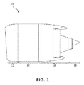
- a noise suppressing structure may be incorporated within or about an inlet portion 12, a thrust reverser portion 16 of a nacelle 10, and/or an exhaust portion 18 of a nacelle 10.
- each cell 202a and 202b may be situated between and/or coupled to a first layer of material 306 and a second layer of material 308.
- first layer 306 and/or a second layer 308 may comprise any of a variety of thin films, or "skins.”
- Lattice 204 may further comprise, for example, a septum 330.
- septum 330 is positioned between first layer 306 and second layer 308.
- septum 330 may be positioned such that first layer 306 and second layer 308 have the same depth.
- the septum may be positioned between approximately 20% and 80% of the depth from first layer 306 to second layer 308, between approximately 30% and 70%, and between about 40% and 60% of the depth between first layer 306 and second layer 308. Any position of septum 330 between first layer 306 and second layer 308 is within the scope of the present disclosure.
- first angle 310 is not equal to about 90 degrees (i.e., first cell portions 212a and/or 214a are not orthogonal to plane 380), first cell 202a and/or second cell 202b may be referred to as "slanted” or “slanting.”
- Second cell portions 212b and/or 214b of cells 202a and/or 202b may, for example, be positioned such that each of the cell walls of second cell portion 212b and/or 214b forms a relative angle 312 with first cell portions 212a and/or 212b.
- relative angle 312 may range from about 20 degrees to about 270 degrees, about 60 to about 180 degrees, and further, about 75 to about 135 degrees. In embodiments in which first angle is about 90 degrees, relative angle 312 will be less than or greater than (i.e., not equal to) 180 degrees.
- first cell portions 212a and 214 are illustrated as aligning with second cell portions 212b and 214b, various cell portions may be out of alignment with each other. Specifically, first cell portions (212a and 214a) and second cell portions (212b and 214b) may be shifted with relation to one another along septum 330 (i.e., in the X direction of Figure 3 ).
- sound waves 420 may enter cells 202a-202d of lattice 204 through perforations in first layer 306. As sound waves 420 travels through each cell, it may pass through septum 330 (as illustrated in cells 202a and 202b) or be reflected by septum 330 (as illustrated in cells 202c and 202d). Sound waves 420 passing through septum 330 are reflected from second layer 308 to exit through perforations in first layer 306. As such, the structure of cells 202a-202d provides a dual degree of freedom design, as will be recognized by those of ordinary skill in this art, and attenuates noise at two effective frequencies or around two frequency bands.
- cells 202a and/or 202b may cancel or suppress sound wave 420 having a lower frequency than cells having walls, for example, which are orthogonal to first layer 306 and/or second layer 308.
- first angle 310 and relative angle 312 maybe varied (increased or decreased) to adjust for a particular acoustic frequency.
- first angle 310 and relative angle 312 may be adjusted to suppress increasingly lower acoustic frequencies. Therefore, cells 202a and 202b may successfully suppress low frequency sound generated by large jet engines, including jet engines utilizing large diameter turbofans.
- slanted cells 202a and 202b may be used in combination with other types of cells.
- slanted cells 202a and 202b may be used with cells which are oriented orthogonally relative to first layer 306 and/or second layer 308.
- slanted cells 202a and 202b may be used with other slanted cells, including those having different characteristics as those of slanted cells 202a and 202b.
- the use of any combination of cells along with slanted cells 202a and 202b, including solely using cells 202a and 202b, is with the scope of the present disclosure.
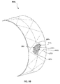
- a nacelle 500B may comprise or may include a support structure comprising a trilateral (e.g., triangular) geometry.
- a support structure (not shown) may comprise a hexagonal and/or octagonal geometry, such as an isostatic hexagonal geometry.
- a support structure may comprise a combination of any of the foregoing geometries as well and/or any other suitable geometry.
Landscapes
- Engineering & Computer Science (AREA)
- Chemical & Material Sciences (AREA)
- Combustion & Propulsion (AREA)
- Mechanical Engineering (AREA)
- General Engineering & Computer Science (AREA)
- Aviation & Aerospace Engineering (AREA)
- Physics & Mathematics (AREA)
- Acoustics & Sound (AREA)
- Multimedia (AREA)
- Soundproofing, Sound Blocking, And Sound Damping (AREA)
Abstract
Description
- The present disclosure relates to acoustic panels for suppressing noise emissions from, for example, a gas propulsion engine on an aircraft, and, more particularly, acoustic panels capable of suppressing lower frequency noises without becoming too thick.
- Propulsion systems for gas turbine engines, such as those that power modem commercial aircraft, typically include noise suppressing structural panels. These structural panels are typically comprised of a plurality of cellular structures or cells between two skins. These cells are often arranged in a lattice, such as a lattice resembling a plurality of "honeycomb" shaped cells. These noise suppressing structures may be utilized in engine components such as nacelles.
- Nacelle designs are trending towards larger fan diameters and thinner architectures, reducing the room for effective acoustic treatment. The lower rotational speeds of larger fan diameters are associated with lower frequency and the increased size of the blades could potentially generate significant tonal noise levels, and typically, thicker panels would be needed to target these frequencies. However, increased thickness means heavier acoustic panels, and more importantly, an increased thickness of an acoustic panel means the overall diameter of the nacelle increases, increasing the size and weight of the entire structure.
- In various embodiments, an aircraft nacelle may comprise a first noise suppressing cell comprising a first cell portion and a second cell portion and positioned between a perforated first layer of material and a septum, wherein the first cell portion contacts the septum at an obtuse first angle relative to the septum, and the second cell portion contacts the septum at a reflex second angle relative to the septum. The septum may be positioned between the perforated first layer of material and the second non-perforated layer of material at a septum distance. The septum distance may be between about 0.40 and 0.60. The first noise suppressing cell may comprise a hexagonal cross-sectional profile and/or one of: a quadrilateral cross-sectional profile, a triangular cross-sectional profile, an octagonal cross-sectional profile, or a circular cross-sectional profile. The obtuse first angle may comprise an angle between about 110 degrees and about 165 degrees. The reflex second angle may comprise an angle between about 200 degrees and about 255 degrees. The noise suppressing structure may comprise a support structure comprising a plurality of support members, and the first noise suppressing cell may be situated within the support structure. The noise suppressing structure may be incorporated within a jet engine nacelle. A wall of the first noise suppressing cell may define a cell depth, wherein the cell depth is between about one inch and about three inches (about 2.54 cm and about 7.62 cm).
- In various embodiments, a nacelle for a jet engine may comprise a first noise suppressing cell comprising a first cell portion and a second cell portion positioned between a perforated first layer of material and a septum, wherein the first cell portion contacts the septum at an obtuse first angle relative to the septum, the second cell portion contacts the septum at a reflex second angle relative to the septum, and the first noise suppressing cell is situated within a support structure defined by a plurality of intersecting support members, and wherein the septum is positioned between the perforated first layer of material and the second non-perforated layer of material at a septum distance. The septum distance may be between about 0.40 and 0.60. The first noise suppressing cell may comprise a hexagonal cross-sectional profile and/or one of: a quadrilateral cross-sectional profile, a triangular cross-sectional profile, an octagonal cross-sectional profile, or a circular cross-sectional profile. The obtuse first angle may comprise an angle between about 110 degrees and about 165 degrees, and the reflex second angle may comprise an angle between about 200 degrees and about 255 degrees.
- The subject matter of the present disclosure is particularly pointed out and distinctly claimed in the concluding portion of the specification. A more complete understanding of the present disclosure, however, may best be obtained by referring to the detailed description and claims when considered in connection with the drawing figures, wherein like numerals denote like elements.
-
Figure 1 illustrates, in accordance with various embodiments, a side view of a nacelle capable of including a plurality of noise suppression structures; -
Figure 2 illustrates, in accordance with various embodiments, a top perspective view of a segment of a noise suppressing structure; -
Figure 3 illustrates, in accordance with various embodiments, a partial cross-sectional view of a plurality of noise suppressing cells; -
Figure 4A illustrates, in accordance with various embodiments, a cross-sectional view of a plurality of noise suppressing cells reflecting a wave front; -
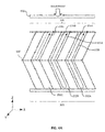
Figure 4B illustrates, in accordance with various embodiments, a cross-sectional view of a plurality of noise suppressing cells; -
Figure 5A illustrates, in accordance with various embodiments, a perspective view of a nacelle comprising a quadrilateral support structure; and -
Figure 5B illustrates, in accordance with various embodiments, a perspective view of a nacelle comprising a trilateral support structure. - The detailed description of exemplary embodiments herein makes reference to the accompanying drawings, which show exemplary embodiments by way of illustration and their best mode. While these exemplary embodiments are described in sufficient detail to enable those skilled in the art to practice the inventions, it should be understood that other embodiments may be realized and that logical, chemical and mechanical changes may be made without departing from the scope of the inventions. Thus, the detailed description herein is presented for purposes of illustration only and not of limitation. For example, the steps recited in any of the method or process descriptions may be executed in any order and are not necessarily limited to the order presented. Furthermore, any reference to singular includes plural embodiments, and any reference to more than one component or step may include a singular embodiment or step. Also, any reference to attached, fixed, connected or the like may include permanent, removable, temporary, partial, full and/or any other possible attachment option. Additionally, any reference to without contact (or similar phrases) may also include reduced contact or minimal contact.
- As used herein, "aft" refers to the direction associated with the tail (e.g., the back end) of an aircraft, or generally, to the direction of exhaust of the gas turbine. As used herein, "forward" refers to the directed associated with the nose (e.g., the front end) of an aircraft, or generally, to the direction of flight or motion.
- A gas turbine engine may include noise suppressing structures. These structures may be comprised of a plurality cellular structures or cells. These cells may be arranged in a lattice, such as a lattice resembling a plurality of "honeycomb" shaped cells. Each cell may act in concert with one or more other cells as part of the larger noise suppressing structure to cancel or suppress noise generated by a gas turbine engine. Cells may be situated between a first layer of material and a second layer of material. Either layer of material may comprise a plurality of perforations through which a sound wave may enter. However, typically, only one of these layers includes perforations. Further, a septum may be positioned between the first layer of material and the second layer of material, separating the cells into a first cell portion and a second cell portion.
- As used herein, "cell depth" may refer to a length of a cell wall formed between the first layer of material and the second layer of material. Cell depth is selected in order to tune the noise attenuation to the desired frequency or frequency range. More particularly, a higher frequency sound wave may be suppressed by a noise suppressing structure having a first cell depth, while a lower frequency sound wave may be suppressed by a noise suppressing structure having a second, greater, cell depth (as a sound wave decreases in frequency, wavelength increases). Noise suppressing structures are therefore generally designed with a particular engine structure and location in mind, as the acoustic frequencies generated by a specific engine component may differ in frequency from those generated by a different engine component.
- Noise suppressing structures are often incorporated variously throughout jet engine nacelles. In particular, one or more noise suppressing structures may be incorporated about an inner and/or outer surface of a wall of a nacelle. The thickness of the nacelle wall is limited, which in turn limits the cell wall depth of an acoustic panel positioned within the nacelle.
- With reference to
Figure 1 , a noise suppressing structure may be incorporated in any suitable location in or near a jet engine and/or within or about anacelle 10 of a jet engine. For example, a noise suppressing structure may be incorporated within or about aninlet portion 12, athrust reverser portion 16 of anacelle 10, and/or anexhaust portion 18 of anacelle 10. - With reference to
Figure 2 , in various embodiments, anoise suppressing structure 200 may, as described herein, be capable of suppressing low frequency sound, even as a cell depth associated with thenoise suppressing structure 200 is reduced.Noise suppressing structure 200 may, for example, comprise one or more cellular structures or cells, such as,cells cells lattice 204 having a variety of cross-sectional profiles (e.g., hexagonal, octagonal, quadrilateral, triangular, circular, and the like). Further,lattice 204 may also comprise, for example, a"honeycomb" shaped structure. - With reference to
Figure 3 , eachcell material 306 and a second layer ofmaterial 308. In various embodiments, either of afirst layer 306 and/or asecond layer 308 may comprise any of a variety of thin films, or "skins." - Either first layer of
material 306 and/or second layer ofmaterial 308 may further comprise a plurality of perforations or holes through which a sound wave may enter. However, in various embodiments, only one of first layer ofmaterial 306 and second layer ofmaterial 308 includes perforations. Thus, as shown, in various embodiments,first layer 306 may comprise one or more perforations, such as, perforations 218a, 218b, and/or 218c. Therefore, as used herein,first layer 306 may be referred to as a "perforated skin" or "top skin." Likewise, second layer ofmaterial 308 may be referred to herein as a "back skin." - In various embodiments, noise suppressing cells may comprise a first cell portion and a second cell portion. For example,
cell 202a may comprise a first cell portion 212a and a second cell portion 212b. Further,cell 202b may comprise a first cell portion 214a and a second cell portion 214b. In various embodiments, first cell portion 212a and/or 214a are in fluid communication with each other, and essentially form a single cell (e.g.,cell 202a and/or 202b). Air enteringfirst layer 306 may pass through first cell portion 212a and/or 214a, into second cell portion 212b and/or 214b, and back to exitfirst layer 306. -
Lattice 204 may further comprise, for example, aseptum 330. In various embodiments,septum 330 is positioned betweenfirst layer 306 andsecond layer 308. For example,septum 330 may be positioned such thatfirst layer 306 andsecond layer 308 have the same depth. Further, the septum may be positioned between approximately 20% and 80% of the depth fromfirst layer 306 tosecond layer 308, between approximately 30% and 70%, and between about 40% and 60% of the depth betweenfirst layer 306 andsecond layer 308. Any position ofseptum 330 betweenfirst layer 306 andsecond layer 308 is within the scope of the present disclosure. -
Septum 330 may comprise, for example, a perforated material. In various embodiments,septum 330 comprises a perforated metal sheet, or a metal mesh or screen-like material, or it could be fashioned in other ways out of different materials as will be apparent to those of skill in this art. Further,septum 330 may comprise the same material asfirst layer 306 and/orsecond layer 308. - In various embodiments,
septum 330 separates first cell portion 212a and/or 214a from second cell portion 212b and/or 214b. For example, a cross-section of a portion oflattice 204 is illustrated inFigure 3A . For example, aplane 380 tangent to nacelle 10 atfirst layer 306 may form afirst angle 310 with first cell portion 212a and/or 214b at the point which the first cells contactfirst layer 306. In various embodiments,first angle 310 may range from about 20 degrees to about 160 degrees, from 30 degrees to about 150 degrees, and further, from about 110 to about 165 degrees (in this context, the term "about" reflects the difficulty in accurately measuring the various angles, and is equivalent to the term "approximate"). In embodiments in whichfirst angle 310 is not equal to about 90 degrees (i.e., first cell portions 212a and/or 214a are not orthogonal to plane 380),first cell 202a and/orsecond cell 202b may be referred to as "slanted" or "slanting." - Second cell portions 212b and/or 214b of
cells 202a and/or 202b may, for example, be positioned such that each of the cell walls of second cell portion 212b and/or 214b forms arelative angle 312 with first cell portions 212a and/or 212b. For example,relative angle 312 may range from about 20 degrees to about 270 degrees, about 60 to about 180 degrees, and further, about 75 to about 135 degrees. In embodiments in which first angle is about 90 degrees,relative angle 312 will be less than or greater than (i.e., not equal to) 180 degrees. - Although first cell portions 212a and 214 are illustrated as aligning with second cell portions 212b and 214b, various cell portions may be out of alignment with each other. Specifically, first cell portions (212a and 214a) and second cell portions (212b and 214b) may be shifted with relation to one another along septum 330 (i.e., in the X direction of
Figure 3 ). - With reference to
Figure 4A ,sound waves 420 may entercells 202a-202d oflattice 204 through perforations infirst layer 306. Assound waves 420 travels through each cell, it may pass through septum 330 (as illustrated incells cells 202c and 202d).Sound waves 420 passing throughseptum 330 are reflected fromsecond layer 308 to exit through perforations infirst layer 306. As such, the structure ofcells 202a-202d provides a dual degree of freedom design, as will be recognized by those of ordinary skill in this art, and attenuates noise at two effective frequencies or around two frequency bands. - Distances 422a and/or 422b that
sound wave 420 travels throughcells 202a and/or 202b is greater than, for example, distances thatsound wave 420 would travel through a cell having walls orthogonal tofirst layer 306,second layer 308, and/orseptum 330. In various embodiments, the length of walls 216a, 216b, and/or 216c may define a cell depth of a slanted cell or a "slanted cell depth." In various embodiments, slanted cell depths may range from about 0.5 to about 5 inches (about 1.27 cm to about 12.7 cm), and further, about 1 inch to about 4 inches (about 2.54 cm to about 10.16 cm). - Thus,
cells 202a and/or 202b may cancel or suppresssound wave 420 having a lower frequency than cells having walls, for example, which are orthogonal tofirst layer 306 and/orsecond layer 308. In addition,first angle 310 andrelative angle 312 maybe varied (increased or decreased) to adjust for a particular acoustic frequency. For example,first angle 310 andrelative angle 312 may be adjusted to suppress increasingly lower acoustic frequencies. Therefore,cells - In various embodiments, slanted
cells cells first layer 306 and/orsecond layer 308. In various embodiments, slantedcells slanted cells cells cells - With reference to
Figure 4B ,cells ribs ribs first layer 306 andsecond layer 308. As such, a plurality of cells (includingcells ribs 440 and 442).Ribs first layer 306 andsecond layer 308, and may "buttress" the wall structure of slatedcells noise suppressing structure 200. When compressive forces are applied to structure 200 in the thickness direction, the core material defining the walls of the cells may collapse and not provide adequate structure resistance to such crushing loads. The reinforcement ribstructure including ribs Ribs 440 and/or 442 may comprise any of a variety of suitable materials, including, for example, a woven and/or layered material, such as a woven and/or layered composite materials. - With reference to
Figure 5A , a nacelle 500A may comprise a plurality of noise suppressing structures, such as for example,noise suppressing structures 200. As described herein,noise suppressing structure 200 may include a plurality of cells such as slantedcells Ribs Figure 5A , the support structure formed byribs Figure 5B , a nacelle 500B may comprise or may include a support structure comprising a trilateral (e.g., triangular) geometry. Further, in various embodiments, a support structure (not shown) may comprise a hexagonal and/or octagonal geometry, such as an isostatic hexagonal geometry. In various embodiments, a support structure may comprise a combination of any of the foregoing geometries as well and/or any other suitable geometry. - Benefits, other advantages, and solutions to problems have been described herein with regard to specific embodiments. Furthermore, the connecting lines shown in the various figures contained herein are intended to represent exemplary functional relationships and/or physical couplings between the various elements. It should be noted that many alternative or additional functional relationships or physical connections may be present in a practical system. However, the benefits, advantages, solutions to problems, and any elements that may cause any benefit, advantage, or solution to occur or become more pronounced are not to be construed as critical, required, or essential features or elements of the inventions. The scope of the inventions is accordingly to be limited by nothing other than the appended claims, in which reference to an element in the singular is not intended to mean "one and only one" unless explicitly so stated, but rather "one or more." Moreover, where a phrase similar to "at least one of A, B, or C" is used in the claims, it is intended that the phrase be interpreted to mean that A alone may be present in an embodiment, B alone may be present in an embodiment, C alone may be present in an embodiment, or that any combination of the elements A, B and C may be present in a single embodiment; for example, A and B, A and C, B and C, or A and B and C. Different cross-hatching is used throughout the figures to denote different parts but not necessarily to denote the same or different materials.
- Systems, methods and apparatus are provided herein. In the detailed description herein, references to "one embodiment", "an embodiment", "various embodiments", etc., indicate that the embodiment described may include a particular feature, structure, or characteristic, but every embodiment may not necessarily include the particular feature, structure, or characteristic. Moreover, such phrases are not necessarily referring to the same embodiment. Further, when a particular feature, structure, or characteristic is described in connection with an embodiment, it is submitted that it is within the knowledge of one skilled in the art to affect such feature, structure, or characteristic in connection with other embodiments whether or not explicitly described. After reading the description, it will be apparent to one skilled in the relevant art(s) how to implement the disclosure in alternative embodiments.
Claims (15)
- A noise suppressing structure (200) comprising:a first noise suppressing cell (202A) comprising a first cell portion (212A) positioned between a perforated first layer of material (306) and a septum (330); anda second cell portion (212B) positioned between the septum (330) and a second layer of material (308), wherein the first cell portion (212A) intersects the perforated first layer of material (306) at a first angle relative to the first layer (306), and the second cell portion (212B) is positioned relative to the first cell portion (212A) at a second relative angle.
- The noise suppressing structure of claim 1, wherein the septum (330) is positioned between the perforated first layer of material (306) and the second layer of material (308) at a septum distance, and the second layer of material (308) is non-perforated.
- The noise suppressing structure of claim 1 or 2, wherein the septum (330) is positioned between about 40% and 60% of the depth between the first and second layers of material (306, 308).
- The noise suppressing structure of claim 1, 2 or 3, wherein the first noise suppressing cell (202A) comprises a hexagonal cross-sectional profile.
- The noise suppressing structure of claim 1, 2 or 3, wherein the first noise suppressing cell (202A) comprises at least one of a quadrilateral cross-sectional profile, a triangular cross-sectional profile, an octagonal cross-sectional profile, or a circular cross-sectional profile.
- The noise suppressing structure of any preceding claim, wherein the first angle comprises an angle between about 110 degrees and about 165 degrees.
- The noise suppressing structure of any preceding claim, wherein the second relative angle comprises an angle between about 70 degrees and about 135 degrees.
- The noise suppressing structure of any preceding claim, further comprising a support structure comprising a plurality of support members (440, 442), wherein the first noise suppressing cell (202A) is situated within the support structure.
- The noise suppressing structure of any preceding claim, wherein the noise suppressing structure (200) is incorporated within a jet engine nacelle (10; 500a; 500b).
- The noise suppressing structure of any preceding claim, wherein a wall of the first noise suppressing cell (202A) defines a cell depth, wherein the cell depth is between about one inch and about three inches (about 2.54 cm and about 7.62 cm).
- A nacelle (10; 500a; 500b) for a jet engine comprising:a first noise suppressing cell (202A) comprising a first cell portion (212A) positioned between a perforated first layer of material (306) and a septum (330) and a second cell portion (212B) positioned between the septum (330) and a second layer of material (308),wherein the first cell portion (212A) contacts the perforated first layer of material (306) at a first angle relative to the first layer of material (306), the second cell portion (212B) contacts the first cell portion (202A) at a second relative angle, and the first noise suppressing cell (202A) is situated within a support structure defined by a plurality of intersecting support members (440, 442), andwherein the septum (330) is positioned between the perforated first layer of material (306) and the second layer of material (308) at a septum distance, and the second layer of material (308) is non-perforated.
- The nacelle for a jet engine of claim 11, wherein the septum distance is between about 40% and 60% of the depth between the first and second layers of material (306, 308).
- The nacelle for a jet engine of claim 11 or 12, wherein the first noise suppressing cell (202A) comprises a hexagonal cross-sectional profile.
- The nacelle for a jet engine of claim 11 or 12, wherein the first noise suppressing cell (202A) comprises one of: a quadrilateral cross-sectional profile, a triangular cross-sectional profile, an octagonal cross-sectional profile, or a circular cross-sectional profile.
- The nacelle for a jet engine of any of claims 11 to 14, wherein the first angle comprises an angle between about 110 degrees and about 165 degrees and the second relative angle comprises an angle between about 70 degrees and about 135 degrees.
Applications Claiming Priority (1)
| Application Number | Priority Date | Filing Date | Title |
|---|---|---|---|
| US14/609,408 US9650963B2 (en) | 2015-01-29 | 2015-01-29 | Acoustic structural panel with herringbone core |
Publications (1)
| Publication Number | Publication Date |
|---|---|
| EP3050807A1 true EP3050807A1 (en) | 2016-08-03 |
Family
ID=55272281
Family Applications (1)
| Application Number | Title | Priority Date | Filing Date |
|---|---|---|---|
| EP16153135.5A Withdrawn EP3050807A1 (en) | 2015-01-29 | 2016-01-28 | Acoustic structural panel with herringbone core |
Country Status (2)
| Country | Link |
|---|---|
| US (1) | US9650963B2 (en) |
| EP (1) | EP3050807A1 (en) |
Cited By (1)
| Publication number | Priority date | Publication date | Assignee | Title |
|---|---|---|---|---|
| EP3553771A1 (en) * | 2018-04-03 | 2019-10-16 | Rohr, Inc. | Structured panel with structural reinforcement(s) |
Families Citing this family (4)
| Publication number | Priority date | Publication date | Assignee | Title |
|---|---|---|---|---|
| US9514734B1 (en) * | 2011-06-30 | 2016-12-06 | The United States Of America As Represented By The Administrator Of National Aeronautics And Space Administration | Acoustic liners for turbine engines |
| US10577117B2 (en) * | 2017-08-04 | 2020-03-03 | Hexcel Corporation | Angled acoustic honeycomb |
| US11398214B2 (en) | 2018-12-14 | 2022-07-26 | Rohr, Inc. | Forming a structured panel with one or more structural reinforcements |
| US11242822B2 (en) | 2018-12-14 | 2022-02-08 | Rohr, Inc. | Structured panel with multi-panel structure(s) |
Citations (4)
| Publication number | Priority date | Publication date | Assignee | Title |
|---|---|---|---|---|
| US5041323A (en) * | 1989-10-26 | 1991-08-20 | Rohr Industries, Inc. | Honeycomb noise attenuation structure |
| GB2252075A (en) * | 1991-01-22 | 1992-07-29 | Short Brothers Plc | Structural cellular component |
| US20140090923A1 (en) * | 2012-05-31 | 2014-04-03 | Rolls-Royce Plc | Acoustic panel |
| WO2014200499A1 (en) * | 2013-06-13 | 2014-12-18 | The Boeing Company | Superplastic forming/diffusion bonding structure for attenuation of noise from air flow |
Family Cites Families (20)
| Publication number | Priority date | Publication date | Assignee | Title |
|---|---|---|---|---|
| US3734234A (en) | 1971-11-08 | 1973-05-22 | Lockheed Aircraft Corp | Sound absorption structure |
| US3821999A (en) | 1972-09-05 | 1974-07-02 | Mc Donnell Douglas Corp | Acoustic liner |
| US3850261A (en) * | 1973-03-01 | 1974-11-26 | Gen Electric | Wide band width single layer sound suppressing panel |
| US3913702A (en) * | 1973-06-04 | 1975-10-21 | Lockheed Aircraft Corp | Cellular sound absorptive structure |
| US4113053A (en) * | 1976-10-06 | 1978-09-12 | Bridgestone Tire Company Limited | Sound absorbing body |
| US4257998A (en) * | 1978-05-01 | 1981-03-24 | The Boenig Company | Method of making a cellular core with internal septum |
| GB2038410B (en) * | 1978-12-27 | 1982-11-17 | Rolls Royce | Acoustic lining utilising resonance |
| US4475624A (en) * | 1981-07-27 | 1984-10-09 | Ltv Aerospace And Defense Company | Honeycomb structure |
| US5923003A (en) | 1996-09-09 | 1999-07-13 | Northrop Grumman Corporation | Extended reaction acoustic liner for jet engines and the like |
| DE19804718C2 (en) * | 1998-02-06 | 2001-09-13 | Eurocopter Deutschland | Sound absorbing sandwich wall |
| GB0016149D0 (en) * | 2000-06-30 | 2000-08-23 | Short Brothers Plc | A noise attenuation panel |
| US6439340B1 (en) * | 2000-11-17 | 2002-08-27 | Astech Manufacturing, Inc. | Acoustically treated structurally reinforced sound absorbing panel |
| US6615576B2 (en) * | 2001-03-29 | 2003-09-09 | Honeywell International Inc. | Tortuous path quiet exhaust eductor system |
| US7331421B2 (en) * | 2005-03-30 | 2008-02-19 | The Boeing Company | Flow restrictors for aircraft inlet acoustic treatments, and associated systems and methods |
| US7434659B2 (en) * | 2005-04-04 | 2008-10-14 | Hexcel Corporation | Acoustic septum cap honeycomb |
| US7540354B2 (en) * | 2006-05-26 | 2009-06-02 | United Technologies Corporation | Micro-perforated acoustic liner |
| US7717229B2 (en) * | 2008-05-09 | 2010-05-18 | Siemens Energy, Inc. | Gas turbine exhaust sound suppressor and associated methods |
| US10294815B2 (en) | 2012-03-01 | 2019-05-21 | The Boeing Company | SPF/DB structure for attenuation of noise from air flow |
| US10184398B2 (en) | 2013-10-17 | 2019-01-22 | Rohr, Inc. | Acoustic structural panel with slanted core |
| US9476359B2 (en) * | 2014-04-11 | 2016-10-25 | Rohr, Inc. | Acoustic liner |
-
2015
- 2015-01-29 US US14/609,408 patent/US9650963B2/en active Active
-
2016
- 2016-01-28 EP EP16153135.5A patent/EP3050807A1/en not_active Withdrawn
Patent Citations (4)
| Publication number | Priority date | Publication date | Assignee | Title |
|---|---|---|---|---|
| US5041323A (en) * | 1989-10-26 | 1991-08-20 | Rohr Industries, Inc. | Honeycomb noise attenuation structure |
| GB2252075A (en) * | 1991-01-22 | 1992-07-29 | Short Brothers Plc | Structural cellular component |
| US20140090923A1 (en) * | 2012-05-31 | 2014-04-03 | Rolls-Royce Plc | Acoustic panel |
| WO2014200499A1 (en) * | 2013-06-13 | 2014-12-18 | The Boeing Company | Superplastic forming/diffusion bonding structure for attenuation of noise from air flow |
Cited By (1)
| Publication number | Priority date | Publication date | Assignee | Title |
|---|---|---|---|---|
| EP3553771A1 (en) * | 2018-04-03 | 2019-10-16 | Rohr, Inc. | Structured panel with structural reinforcement(s) |
Also Published As
| Publication number | Publication date |
|---|---|
| US9650963B2 (en) | 2017-05-16 |
| US20160312709A1 (en) | 2016-10-27 |
Similar Documents
| Publication | Publication Date | Title |
|---|---|---|
| US10184398B2 (en) | Acoustic structural panel with slanted core | |
| US9650963B2 (en) | Acoustic structural panel with herringbone core | |
| EP3450738B1 (en) | Acoustic liner having internal structure | |
| US11227576B2 (en) | Continuous degree of freedom acoustic cores | |
| EP3232435B1 (en) | Acoustic panel with corrugated baffles and septums | |
| JP6634454B2 (en) | Acoustic liner for use in turbine engines | |
| EP2953130B1 (en) | Acoustically attenuating sandwich panel constructions | |
| US20200200084A1 (en) | Acoustic panel for a nacelle of an aircraft propulsion unit, and related manufacturing methods | |
| EP3422342A1 (en) | Acoustic panel with folding chamber | |
| US8863893B2 (en) | Engine inlet varying impedance acoustic liner section | |
| EP3618056B1 (en) | Continuous slanted cell septum | |
| EP3244038A1 (en) | Acoustic panels comprising large secondary cavities to attenuate low frequencies | |
| US9670878B2 (en) | Cellular acoustic structure for a turbojet engine and turbojet engine incorporating at least one such structure | |
| EP2669501A2 (en) | Acoustic panel | |
| US12196115B2 (en) | Propulsion flow path duct systems and methods | |
| EP3625439B1 (en) | Outlet guide vanes | |
| US20160215700A1 (en) | Inner fixed structure acoustic panel with directional perforations | |
| US11268478B2 (en) | Sound-proofing covering comprising a cellular structure with curved cells formed on either side of one and the same inner wall | |
| CN112776995A (en) | Multifrequency absorbing acoustic panel for aircraft engine nacelle | |
| US12170077B2 (en) | Acoustic attenuation panel for low-frequency waves | |
| US11459950B2 (en) | Sound attenuation panel for aircraft having a combination of acoustic attenuation properties | |
| EP2865877B1 (en) | Acoustically treated thrust reverser track beam |
Legal Events
| Date | Code | Title | Description |
|---|---|---|---|
| PUAI | Public reference made under article 153(3) epc to a published international application that has entered the european phase |
Free format text: ORIGINAL CODE: 0009012 |
|
| AK | Designated contracting states |
Kind code of ref document: A1 Designated state(s): AL AT BE BG CH CY CZ DE DK EE ES FI FR GB GR HR HU IE IS IT LI LT LU LV MC MK MT NL NO PL PT RO RS SE SI SK SM TR |
|
| AX | Request for extension of the european patent |
Extension state: BA ME |
|
| 17P | Request for examination filed |
Effective date: 20170203 |
|
| RBV | Designated contracting states (corrected) |
Designated state(s): AL AT BE BG CH CY CZ DE DK EE ES FI FR GB GR HR HU IE IS IT LI LT LU LV MC MK MT NL NO PL PT RO RS SE SI SK SM TR |
|
| STAA | Information on the status of an ep patent application or granted ep patent |
Free format text: STATUS: THE APPLICATION HAS BEEN WITHDRAWN |
|
| 18W | Application withdrawn |
Effective date: 20170914 |