EP3050612A1 - Enhanced device for separation of oxygen and nitrogen - Google Patents
Enhanced device for separation of oxygen and nitrogen Download PDFInfo
- Publication number
- EP3050612A1 EP3050612A1 EP16153295.7A EP16153295A EP3050612A1 EP 3050612 A1 EP3050612 A1 EP 3050612A1 EP 16153295 A EP16153295 A EP 16153295A EP 3050612 A1 EP3050612 A1 EP 3050612A1
- Authority
- EP
- European Patent Office
- Prior art keywords
- membrane
- metal foam
- nitrogen
- porous metal
- oxygen
- Prior art date
- Legal status (The legal status is an assumption and is not a legal conclusion. Google has not performed a legal analysis and makes no representation as to the accuracy of the status listed.)
- Granted
Links
Images


Classifications
-
- B—PERFORMING OPERATIONS; TRANSPORTING
- B01—PHYSICAL OR CHEMICAL PROCESSES OR APPARATUS IN GENERAL
- B01D—SEPARATION
- B01D53/00—Separation of gases or vapours; Recovering vapours of volatile solvents from gases; Chemical or biological purification of waste gases, e.g. engine exhaust gases, smoke, fumes, flue gases, aerosols
- B01D53/22—Separation of gases or vapours; Recovering vapours of volatile solvents from gases; Chemical or biological purification of waste gases, e.g. engine exhaust gases, smoke, fumes, flue gases, aerosols by diffusion
-
- B—PERFORMING OPERATIONS; TRANSPORTING
- B01—PHYSICAL OR CHEMICAL PROCESSES OR APPARATUS IN GENERAL
- B01D—SEPARATION
- B01D63/00—Apparatus in general for separation processes using semi-permeable membranes
- B01D63/02—Hollow fibre modules
- B01D63/032—More than two tube sheets for one bundle
-
- B—PERFORMING OPERATIONS; TRANSPORTING
- B01—PHYSICAL OR CHEMICAL PROCESSES OR APPARATUS IN GENERAL
- B01D—SEPARATION
- B01D53/00—Separation of gases or vapours; Recovering vapours of volatile solvents from gases; Chemical or biological purification of waste gases, e.g. engine exhaust gases, smoke, fumes, flue gases, aerosols
- B01D53/22—Separation of gases or vapours; Recovering vapours of volatile solvents from gases; Chemical or biological purification of waste gases, e.g. engine exhaust gases, smoke, fumes, flue gases, aerosols by diffusion
- B01D2053/221—Devices
- B01D2053/223—Devices with hollow tubes
- B01D2053/224—Devices with hollow tubes with hollow fibres
-
- B—PERFORMING OPERATIONS; TRANSPORTING
- B01—PHYSICAL OR CHEMICAL PROCESSES OR APPARATUS IN GENERAL
- B01D—SEPARATION
- B01D2256/00—Main component in the product gas stream after treatment
- B01D2256/10—Nitrogen
-
- B—PERFORMING OPERATIONS; TRANSPORTING
- B01—PHYSICAL OR CHEMICAL PROCESSES OR APPARATUS IN GENERAL
- B01D—SEPARATION
- B01D2256/00—Main component in the product gas stream after treatment
- B01D2256/12—Oxygen
-
- B—PERFORMING OPERATIONS; TRANSPORTING
- B01—PHYSICAL OR CHEMICAL PROCESSES OR APPARATUS IN GENERAL
- B01D—SEPARATION
- B01D2257/00—Components to be removed
- B01D2257/10—Single element gases other than halogens
- B01D2257/102—Nitrogen
-
- B—PERFORMING OPERATIONS; TRANSPORTING
- B01—PHYSICAL OR CHEMICAL PROCESSES OR APPARATUS IN GENERAL
- B01D—SEPARATION
- B01D2257/00—Components to be removed
- B01D2257/10—Single element gases other than halogens
- B01D2257/104—Oxygen
-
- B—PERFORMING OPERATIONS; TRANSPORTING
- B01—PHYSICAL OR CHEMICAL PROCESSES OR APPARATUS IN GENERAL
- B01D—SEPARATION
- B01D2259/00—Type of treatment
- B01D2259/45—Gas separation or purification devices adapted for specific applications
- B01D2259/4566—Gas separation or purification devices adapted for specific applications for use in transportation means
- B01D2259/4575—Gas separation or purification devices adapted for specific applications for use in transportation means in aeroplanes or space ships
-
- B—PERFORMING OPERATIONS; TRANSPORTING
- B64—AIRCRAFT; AVIATION; COSMONAUTICS
- B64D—EQUIPMENT FOR FITTING IN OR TO AIRCRAFT; FLIGHT SUITS; PARACHUTES; ARRANGEMENT OR MOUNTING OF POWER PLANTS OR PROPULSION TRANSMISSIONS IN AIRCRAFT
- B64D37/00—Arrangements in connection with fuel supply for power plant
- B64D37/32—Safety measures not otherwise provided for, e.g. preventing explosive conditions
Definitions
- OEA or NEA there are, of course, many uses for OEA or NEA, so there are a variety of applications for devices that separate oxygen and nitrogen, including but not limited to medical oxygen concentrators, atmospheric oxygen supplementation systems, and NEA-based combustion suppression systems.
- NEA-based combustion suppression systems include but not limited to medical oxygen concentrators, atmospheric oxygen supplementation systems, and NEA-based combustion suppression systems.
- commercial and other aircraft have been equipped with fuel tank suppression systems that introduce NEA into a fuel tank headspace or ullage, often by bubbling NEA through the liquid fuel.
- Such systems require NEA with a nitrogen concentration of at least 90 % by volume, and attempt to minimize payload weight and size while maintaining target NEA output across a wide variety of operating conditions.
- An inerting system decreases the probability of combustion of flammable fuel vapors in a fuel tank by maintaining a chemically non-reactive or inert gas, such as nitrogen, in the fuel tank vapor space also known as ullage.
- a chemically non-reactive or inert gas such as nitrogen
- oxidizer e.g., oxygen
- the tank may be made inert by: 1) reducing the oxygen concentration threshold, 2) reducing the fuel concentration of the ullage to below the lower explosive limit (LEL), or 3) increasing the fuel concentration to above the upper explosive limit (UEL).
- LEL lower explosive limit
- UEL upper explosive limit
- Membrane devices offer many advantages for use in aircraft applications to provide a source of NEA.
- service life of membrane devices for separating oxygen and nitrogen can be limited by the polymers used in the gas separation module.
- These polymers are susceptible to damage by air-borne contaminants in the media flow including but not limited to hydrocarbons (HCs), liquid or solid aerosols.
- Contaminants can affect the service life of the membrane in several ways. Liquid/solid particulates can plug the membrane. Liquids can soak the membrane causing swelling, distortion, and, ultimately structural failure of the affected membrane.
- Various acids and solvents can damage the inner walls of the composite or layered membranes, causing delamination and membrane deformation. Prolonged exposure to heavy HCs can lead to degradation, cracking, and structural damage of the polymer materials used in forming the membranes.
- Contamination of the gas separation membrane can be a problem in any operating environment, but can be particularly problematic for on-board aircraft applications. More specifically, air-borne contaminants may include (but are not limited to): residue products from jet fuel, engine lubricating oil, hydraulic fluid, de-icing fluid, and various ambient pollutants in the atmosphere (exhausts from other aircraft, smog, acid rain, etc.). Especially damaging to the membrane can be contaminants such as ketones, acids, and aldehydes. In general, membranes are susceptible to damage from large hydrocarbon molecules such as those commonly found in the complex combustion products of typical jet fuel-powered aircraft engines.
- a device for separating nitrogen and oxygen comprises an inlet in fluid communication with a source of a gas comprising oxygen and nitrogen, a membrane having a greater permeability to oxygen than to nitrogen, and having a first and a second side, with the first side in fluid communication with the inlet, an outlet for nitrogen-enriched gas in fluid communication with the second side of the membrane, an outlet for oxygen-enriched gas in fluid communication with the first side of the membrane, and a porous metal foam between the inlet and the membrane.
- a method separating oxygen from nitrogen comprises passing a gas comprising nitrogen and oxygen through a porous metal foam, delivering the gas exiting the porous metal foam to a first side of a membrane having a greater permeability to oxygen than to nitrogen, and diffusing oxygen in the gas through the membrane to a second side of the membrane to produce an oxygen-enriched gas on the second side of the membrane and a nitrogen-enriched gas on the first side of the membrane.
- FIG. 1 schematically depicts an exemplary membrane for separating nitrogen and oxygen.
- FIG. 1 depicts a tubular membrane, but other configurations such as planar membranes can also be used.
- tubular membrane 20 comprises a tubular shell 22.
- the membrane 20 can be fabricated from a material that has selective permeability to oxygen compared to nitrogen such that a pressure differential across the membrane provided by a gas comprising nitrogen and oxygen on the high-pressure side of the membrane will preferentially diffuse oxygen molecules across the membrane.
- the membrane 20 is depicted as a monolithic hollow shell, and membranes fabricated solely out of the selective oxygen-permeable membrane material are included within the scope of this invention.
- the membrane is a composite of a substrate or layer that is permeable to both oxygen and nitrogen and a substrate or layer that is selectively permeable to oxygen.
- the shell 22 defines a hollow core 26 that is open at both ends.
- pressurized gas comprising nitrogen and oxygen (e.g., air which is known to also contain trace amounts of noble/inert gases) is delivered into the hollow core 26 at an inlet end 27 of the membrane 20.
- the pressure of the air is greater than air outside the core 26 such that a pressure differential between the hollow core 26 and air at the exterior 24 of the membrane 20 exists.
- Oxygen molecules preferentially diffuse through the tubular membrane 20 compared to nitrogen molecules, resulting in a flow of OEA from the outer surface of the tubular membrane 20 as shown in FIG. 1 , and a flow of NEA from the hollow core 26 at the outlet end 28 of the membrane 20 as shown in FIG. 1 .
- porous metal foam is disposed in the flow of air before it contacts the membrane 20.
- Porous metal foams are commercially available offering a wide variety of configurations and properties.
- Porous metal foams used herein should be sufficiently porous to meet the gas pressure and flow rate requirements for the membrane air separator. Although these requirements can vary widely, in some exemplary embodiments, the porous metal foam can be an open-cell foam with a pore density of about 50 pores/inch (0.508 mm pore size) to about 200 pores/inch (0.127 mm pore size) (pore counts are specified per linear inch as observed on the surface of the foam).
- the pores can be irregular or they can be configured in a regular configuration, depending on the fabrication technique.
- the porous metal foam is heated by flowing electric current through it, and the foam should provide a level of electrical conductivity and heat transfer characteristics conducive to such heating.
- the porous metal foam is a screen having an electrical conductivity, ⁇ , of from about 3x10 4 Siemens/m to about 1x10 6 Siemens/m measured laterally along the screen.
- the porous metal foam has a thermal conductivity, k, of from about 0.3 W/(m ⁇ K) to 35 W/(m ⁇ K) and relatively low density from about 0.4 g/cm 3 to about 0.9 g/cm 3 .
- porous metal foams can be used in the porous metal foams as described herein, including but not limited to Fe-Cr-Al, Ni-Cr, Al-SiC, Al-Ca, Al-TiH, etc.
- the porous metal foams can be fabricated by a variety of techniques, including but not limited to coating or impregnating a polymer foam with a slurry of a metal powder in a liquid carrier, drying off the liquid, and sintering the metal powder. The heat of the sintering process also pyrolyzes the polymer foam, leaving a metal foam based off of the polymer foam template.
- Other techniques such as metal vapor deposition or electroless plating, can also be used to coat or impregnate a polymer foam with metal, followed by heating step to pyrolyze the polymer foam.
- the porous metal foam can be deployed as a monolithic brick or as a thin screen or series of screens.
- Porous metal foam screens can have a wide range of thicknesses, and in some exemplary embodiments have a thickness of from about 0.5 mm to 5 mm.
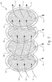
- FIG. 2 depicts an exemplary embodiment of a series of porous metal foam screens 100. As shown in FIG. 2 , air 102 flowing toward a membrane air separator passes through porous metal foam screens 104, 106, 108, and 110 before exiting as decontaminated air 112. Contaminants 114 are removed from the air and, unlike many conventional filters, they are not retained by the metal foam, but are instead released as shown in FIG. 2 . Solid contaminants that strike a metal surface on the foam screen tend to bounce off and fall away.
- Liquid contaminants can be removed by applying an electric current to heat the porous metal foam screen sufficiently high to evaporate the liquid or reduce its viscosity so that it flows off of the screen as part of contaminants 114 shown in FIG. 2 .
- Solid or liquid contaminants that penetrate through a pore in the porous metal foam screen can be removed by any of the successive screens, with a sufficient number of screens in series to achieve target contaminant levels. If the screens utilize a regular pore pattern, they can be each successively angularly offset so that the pores do not line up with one another in order to increase the effectiveness of the screens lined up in series.
- a device 30 comprising multiple tubular membranes 20 for separating oxygen and nitrogen is schematically depicted.
- a device 30 for separating oxygen and nitrogen has an intake plenum 32 with inlet 34 for receiving air from an air source (not shown) such as a compressor or vehicle air intake. Air in the intake plenum flows into the hollow cores 26 ( FIG. 1 ) of tubular membranes 20 towards discharge plenum 36, where it is collected and discharged through NEA outlet 38. Oxygen flowing through the hollow cores 26 of the tubular membranes 20 preferentially (versus nitrogen) diffuses through the tubular membranes 20, so that the gas discharged into discharge plenum 36 is nitrogen enhanced.
- a housing 40 is disposed around the tubular membranes 20 and forms a sealed connection with the intake plenum 32 and the discharge plenum 36.
- the tubular membranes 20 also form sealed connections at each end with the intake plenum 32 and discharge plenum 36, respectively, so that housing 40 together with the inner surfaces of the plenums 32, 36 forms a chamber for collecting oxygen-enhanced air, which is discharged through OEA outlet 42.
- OEA outlet 42 oxygen-enhanced air
- a series of metal screens 44, 46, 48, and 50 is disposed in the airflow path prior to its entry into the tubular membranes 20.
- the housing of the plenum 32 is extended to section 52 below the airflow path for collection and accumulation of debris.
- the porous metal foam screens 44, 46, 48, and 50 are each electrically connected to a ground 54 at one end and to DC power source and controller 56 at the other end. It should be noted that these electrical connections are depicted as for a square or rectangularly-shaped screen, and that different electrical connection locations would be used for other configurations such as for round screens.
- the controller 56 controls the electric current applied to the porous metal foam screens to achieve a target temperature.
- a target temperature is at least 5°C in order to ensure melting of any water-containing contaminants. Temperature of the screens can be detected and controlled by treating the screens as resistance temperature detector (RTD) where temperature as a function of electrical resistance across the screen is known so that the controller 56 measures electrical resistance across the screen and controls the current to achieve a target electrical resistance representative of temperature.
- RTD resistance temperature detector
- the controller utilizes pulse width modulation (PWM) to control the electric current applied to the porous metal foam screens, where square wave periodic pulses of current are applied with level of heating controlled by varying the duration of the pulses (i.e., the width of the pulses when plotted as electrical current (y-axis) versus time (x-axis)).
- PWM pulse width modulation
- the controller 56 can be a stand-alone controller or it can be networked with a system controller such as an aircraft master controller or subsystem controller.
- the controller 56 receives a NEA demand signal from another controller such as a master controller or a fuel system management controller, or the controller 56 could be the fuel system management controller having connections to other fuel system components besides those depicted in FIG. 3
- the section 52 may be sufficient to collect contaminants for the life of the device or of a porous metal foam screen module without being evacuated or cleaned.
- an optional drain with a simple non-return (check) valve 58 (which can optionally be controlled by controller 56) is disposed at the end of the plenum section 52 for removing accumulated liquid contaminants.
- Accumulated solid contaminants can be removed over time by decomposition promoted by repeated cycles of heating the porous metal foam screens.
- Solid components can be removed from the section 52 with an optional high speed air or liquid cleaning flushing stream flowing through optional valved conduit openings 60 and 62 controlled by controller 56 during a recycle stage performed when there is no system demand for NEA production.
- the depicted design could be altered so that the porous metal foam screens do not extend past the openings 60 and 62 having valves 64 and 66 respectively.
- the porous metal foam screens 44, 46, 48, 50 are depicted in FIG. 3 extending to the bottom of section 52 of the plenum housing 32, which can provide robust electrical connection as well as the capability of applying repeated heat cycles to decompose or evaporate accumulated contaminants in the section 52.
- the porous metal foam screens do not extend or extend only partway into section 52, or where there is no section 52 present.
Landscapes
- Chemical & Material Sciences (AREA)
- Chemical Kinetics & Catalysis (AREA)
- Engineering & Computer Science (AREA)
- Analytical Chemistry (AREA)
- General Chemical & Material Sciences (AREA)
- Oil, Petroleum & Natural Gas (AREA)
- Separation Using Semi-Permeable Membranes (AREA)
Abstract
Description
- Various devices have been utilized over time for the separation of nitrogen and oxygen from air. Many such devices rely on a membrane that is exposed to pressurized air, such that oxygen molecules preferentially (compared to the larger nitrogen molecules) diffuse through the membrane, resulting in an oxygen-enriched gas on one side of the membrane and a nitrogen-rich gas on the other side of the membrane. These gases are also referred to as oxygen-enriched air (OEA) and nitrogen-enriched air (NEA), respectively. The effectiveness of membranes at performing the task of separating gases can be characterized by a trade-off that membranes experience between permeability of the membrane to the gas molecules targeted for diffusion across the membrane versus selectivity of the membrane between the targeted gas molecules and other molecules in the gas mixture.
- There are, of course, many uses for OEA or NEA, so there are a variety of applications for devices that separate oxygen and nitrogen, including but not limited to medical oxygen concentrators, atmospheric oxygen supplementation systems, and NEA-based combustion suppression systems. In recent years, commercial and other aircraft have been equipped with fuel tank suppression systems that introduce NEA into a fuel tank headspace or ullage, often by bubbling NEA through the liquid fuel. Such systems require NEA with a nitrogen concentration of at least 90 % by volume, and attempt to minimize payload weight and size while maintaining target NEA output across a wide variety of operating conditions.
- It is recognized that fuel vapors within fuel tanks become combustible in the presence of oxygen. An inerting system decreases the probability of combustion of flammable fuel vapors in a fuel tank by maintaining a chemically non-reactive or inert gas, such as nitrogen, in the fuel tank vapor space also known as ullage. Three elements are required to initiate and sustain combustion: an ignition source (e.g., heat, electrostatic spark, etc.), fuel, and oxidizer (e.g., oxygen). Combustion may be prevented by reducing any one of these three elements. If the presence of an ignition source cannot be prevented within a fuel tank, then the tank may be made inert by: 1) reducing the oxygen concentration threshold, 2) reducing the fuel concentration of the ullage to below the lower explosive limit (LEL), or 3) increasing the fuel concentration to above the upper explosive limit (UEL). Many systems reduce the risk of combustion by reducing the oxygen concentration by introducing an inert gas such as nitrogen to the ullage, thereby displacing some of the oxygen in the fuel tank with nitrogen.
- Membrane devices offer many advantages for use in aircraft applications to provide a source of NEA. However, service life of membrane devices for separating oxygen and nitrogen can be limited by the polymers used in the gas separation module. These polymers are susceptible to damage by air-borne contaminants in the media flow including but not limited to hydrocarbons (HCs), liquid or solid aerosols. Contaminants can affect the service life of the membrane in several ways. Liquid/solid particulates can plug the membrane. Liquids can soak the membrane causing swelling, distortion, and, ultimately structural failure of the affected membrane. Various acids and solvents can damage the inner walls of the composite or layered membranes, causing delamination and membrane deformation. Prolonged exposure to heavy HCs can lead to degradation, cracking, and structural damage of the polymer materials used in forming the membranes.
- Contamination of the gas separation membrane can be a problem in any operating environment, but can be particularly problematic for on-board aircraft applications. More specifically, air-borne contaminants may include (but are not limited to): residue products from jet fuel, engine lubricating oil, hydraulic fluid, de-icing fluid, and various ambient pollutants in the atmosphere (exhausts from other aircraft, smog, acid rain, etc.). Especially damaging to the membrane can be contaminants such as ketones, acids, and aldehydes. In general, membranes are susceptible to damage from large hydrocarbon molecules such as those commonly found in the complex combustion products of typical jet fuel-powered aircraft engines.
- According to some aspects of the invention, a device for separating nitrogen and oxygen comprises an inlet in fluid communication with a source of a gas comprising oxygen and nitrogen, a membrane having a greater permeability to oxygen than to nitrogen, and having a first and a second side, with the first side in fluid communication with the inlet, an outlet for nitrogen-enriched gas in fluid communication with the second side of the membrane, an outlet for oxygen-enriched gas in fluid communication with the first side of the membrane, and a porous metal foam between the inlet and the membrane.
- According to some aspects of the invention, a method separating oxygen from nitrogen comprises passing a gas comprising nitrogen and oxygen through a porous metal foam, delivering the gas exiting the porous metal foam to a first side of a membrane having a greater permeability to oxygen than to nitrogen, and diffusing oxygen in the gas through the membrane to a second side of the membrane to produce an oxygen-enriched gas on the second side of the membrane and a nitrogen-enriched gas on the first side of the membrane.
- The subject matter which is regarded as the invention is particularly pointed out and distinctly claimed in the claims at the conclusion of the specification. The foregoing and other features, and advantages of the invention are apparent by way of example only from the following detailed description taken in conjunction with the accompanying figures, in which:
-
FIG. 1 is a schematic depiction of an exemplary tubular membrane for separating nitrogen and oxygen; -
FIG. 2 is a schematic depiction of an exemplary configuration of a porous metal foam for use in conjunction with a membrane for separating nitrogen and oxygen; and -
FIG. 3 is a schematic depiction of an exemplary device for separating oxygen and nitrogen. - With reference to the Figures,
FIG. 1 schematically depicts an exemplary membrane for separating nitrogen and oxygen.FIG. 1 depicts a tubular membrane, but other configurations such as planar membranes can also be used. As shown inFig. 1 ,tubular membrane 20 comprises a tubular shell 22. Themembrane 20 can be fabricated from a material that has selective permeability to oxygen compared to nitrogen such that a pressure differential across the membrane provided by a gas comprising nitrogen and oxygen on the high-pressure side of the membrane will preferentially diffuse oxygen molecules across the membrane. For ease of illustration, themembrane 20 is depicted as a monolithic hollow shell, and membranes fabricated solely out of the selective oxygen-permeable membrane material are included within the scope of this invention. However, in many cases, the membrane is a composite of a substrate or layer that is permeable to both oxygen and nitrogen and a substrate or layer that is selectively permeable to oxygen. - The shell 22 defines a
hollow core 26 that is open at both ends. In use, pressurized gas comprising nitrogen and oxygen (e.g., air which is known to also contain trace amounts of noble/inert gases) is delivered into thehollow core 26 at aninlet end 27 of themembrane 20. The pressure of the air is greater than air outside thecore 26 such that a pressure differential between thehollow core 26 and air at theexterior 24 of themembrane 20 exists. Oxygen molecules preferentially diffuse through thetubular membrane 20 compared to nitrogen molecules, resulting in a flow of OEA from the outer surface of thetubular membrane 20 as shown inFIG. 1 , and a flow of NEA from thehollow core 26 at theoutlet end 28 of themembrane 20 as shown inFIG. 1 . - As described above, a porous metal foam is disposed in the flow of air before it contacts the
membrane 20. Porous metal foams are commercially available offering a wide variety of configurations and properties. Porous metal foams used herein should be sufficiently porous to meet the gas pressure and flow rate requirements for the membrane air separator. Although these requirements can vary widely, in some exemplary embodiments, the porous metal foam can be an open-cell foam with a pore density of about 50 pores/inch (0.508 mm pore size) to about 200 pores/inch (0.127 mm pore size) (pore counts are specified per linear inch as observed on the surface of the foam). The pores can be irregular or they can be configured in a regular configuration, depending on the fabrication technique. In some embodiments, the porous metal foam is heated by flowing electric current through it, and the foam should provide a level of electrical conductivity and heat transfer characteristics conducive to such heating. In some exemplary embodiments, the porous metal foam is a screen having an electrical conductivity, σ, of from about 3x10⁴ Siemens/m to about 1x10⁶ Siemens/m measured laterally along the screen. In some exemplary embodiments, the porous metal foam has a thermal conductivity, k, of from about 0.3 W/(m·K) to 35 W/(m·K) and relatively low density from about 0.4 g/cm3 to about 0.9 g/cm3. - A wide variety of metals and metal alloys can be used in the porous metal foams as described herein, including but not limited to Fe-Cr-Al, Ni-Cr, Al-SiC, Al-Ca, Al-TiH, etc. The porous metal foams can be fabricated by a variety of techniques, including but not limited to coating or impregnating a polymer foam with a slurry of a metal powder in a liquid carrier, drying off the liquid, and sintering the metal powder. The heat of the sintering process also pyrolyzes the polymer foam, leaving a metal foam based off of the polymer foam template. Other techniques, such as metal vapor deposition or electroless plating, can also be used to coat or impregnate a polymer foam with metal, followed by heating step to pyrolyze the polymer foam.
- The porous metal foam can be deployed as a monolithic brick or as a thin screen or series of screens. Porous metal foam screens can have a wide range of thicknesses, and in some exemplary embodiments have a thickness of from about 0.5 mm to 5 mm.
FIG. 2 depicts an exemplary embodiment of a series of porousmetal foam screens 100. As shown inFIG. 2 ,air 102 flowing toward a membrane air separator passes through porousmetal foam screens air 112.Contaminants 114 are removed from the air and, unlike many conventional filters, they are not retained by the metal foam, but are instead released as shown inFIG. 2 . Solid contaminants that strike a metal surface on the foam screen tend to bounce off and fall away. Liquid contaminants can be removed by applying an electric current to heat the porous metal foam screen sufficiently high to evaporate the liquid or reduce its viscosity so that it flows off of the screen as part ofcontaminants 114 shown inFIG. 2 . Solid or liquid contaminants that penetrate through a pore in the porous metal foam screen can be removed by any of the successive screens, with a sufficient number of screens in series to achieve target contaminant levels. If the screens utilize a regular pore pattern, they can be each successively angularly offset so that the pores do not line up with one another in order to increase the effectiveness of the screens lined up in series. - Turning now to
FIG. 3 , adevice 30 comprising multipletubular membranes 20 for separating oxygen and nitrogen is schematically depicted. As shown inFIG. 3 , adevice 30 for separating oxygen and nitrogen has anintake plenum 32 withinlet 34 for receiving air from an air source (not shown) such as a compressor or vehicle air intake. Air in the intake plenum flows into the hollow cores 26 (FIG. 1 ) oftubular membranes 20 towardsdischarge plenum 36, where it is collected and discharged throughNEA outlet 38. Oxygen flowing through thehollow cores 26 of thetubular membranes 20 preferentially (versus nitrogen) diffuses through thetubular membranes 20, so that the gas discharged intodischarge plenum 36 is nitrogen enhanced. Ahousing 40 is disposed around thetubular membranes 20 and forms a sealed connection with theintake plenum 32 and thedischarge plenum 36. Thetubular membranes 20 also form sealed connections at each end with theintake plenum 32 anddischarge plenum 36, respectively, so thathousing 40 together with the inner surfaces of theplenums OEA outlet 42. It will be appreciated that, based on the guidance provided herein, one skilled in the art would set component sizes (e.g., core and outside fiber diameters), number of fibers, etc., and also to set operating parameters such as control valve settings at the inlet and the outlets to provide pressure differentials and gas flow amounts to achieve a target gas diffusion profile through the membranes. - As further shown in
FIG. 3 , a series ofmetal screens tubular membranes 20. The housing of theplenum 32 is extended tosection 52 below the airflow path for collection and accumulation of debris. The porous metal foam screens 44, 46, 48, and 50 are each electrically connected to aground 54 at one end and to DC power source andcontroller 56 at the other end. It should be noted that these electrical connections are depicted as for a square or rectangularly-shaped screen, and that different electrical connection locations would be used for other configurations such as for round screens. In some exemplary embodiments, thecontroller 56 controls the electric current applied to the porous metal foam screens to achieve a target temperature. In some exemplary embodiments, a target temperature is at least 5°C in order to ensure melting of any water-containing contaminants. Temperature of the screens can be detected and controlled by treating the screens as resistance temperature detector (RTD) where temperature as a function of electrical resistance across the screen is known so that thecontroller 56 measures electrical resistance across the screen and controls the current to achieve a target electrical resistance representative of temperature. In some exemplary embodiments, the controller utilizes pulse width modulation (PWM) to control the electric current applied to the porous metal foam screens, where square wave periodic pulses of current are applied with level of heating controlled by varying the duration of the pulses (i.e., the width of the pulses when plotted as electrical current (y-axis) versus time (x-axis)). Thecontroller 56 can be a stand-alone controller or it can be networked with a system controller such as an aircraft master controller or subsystem controller. For example, in some embodiments thecontroller 56 receives a NEA demand signal from another controller such as a master controller or a fuel system management controller, or thecontroller 56 could be the fuel system management controller having connections to other fuel system components besides those depicted inFIG. 3 - Depending on the contaminant levels in the air expected over the life of the device, the
section 52 may be sufficient to collect contaminants for the life of the device or of a porous metal foam screen module without being evacuated or cleaned. In some exemplary embodiments, however, an optional drain with a simple non-return (check) valve 58 (which can optionally be controlled by controller 56) is disposed at the end of theplenum section 52 for removing accumulated liquid contaminants. Accumulated solid contaminants can be removed over time by decomposition promoted by repeated cycles of heating the porous metal foam screens. Solid components can be removed from thesection 52 with an optional high speed air or liquid cleaning flushing stream flowing through optionalvalved conduit openings controller 56 during a recycle stage performed when there is no system demand for NEA production. In cases of severe solid particle accumulation, the depicted design could be altered so that the porous metal foam screens do not extend past theopenings valves FIG. 3 extending to the bottom ofsection 52 of theplenum housing 32, which can provide robust electrical connection as well as the capability of applying repeated heat cycles to decompose or evaporate accumulated contaminants in thesection 52. However, embodiments are also contemplated where the porous metal foam screens do not extend or extend only partway intosection 52, or where there is nosection 52 present. - While the invention has been described in detail in connection with only a limited number of embodiments, it should be readily understood that the invention is not limited to such disclosed embodiments. Rather, the invention can be modified to incorporate any number of variations, alterations or substitutions not heretofore described, but which are commensurate with the scope of the invention. Additionally, while various embodiments of the invention have been described, it is to be understood that aspects of the invention may include only some of the described embodiments. Accordingly, the invention is not to be seen as limited by the foregoing description, but is only limited by the scope of the appended claims.
Claims (15)
- A device (30) for separating nitrogen and oxygen, comprising
an inlet (34) in fluid communication with a source of a gas comprising oxygen and nitrogen;
a membrane (20) having a greater permeability to oxygen than to nitrogen, and having a first and a second side, with the first side in fluid communication with the inlet (34);
an outlet (38) for nitrogen-enriched gas in fluid communication with the second side of the membrane;
an outlet (42) for oxygen-enriched gas in fluid communication with the first side of the membrane; and
a porous metal foam between the inlet (34) and the membrane (20). - The device (30) of claim 1, wherein the membrane (20) comprises a hollow polymer fiber wherein the polymer substrate is configured as a polymer shell (22) surrounding a hollow core (26), the hollow core (26) extending from one end of the fiber to the other end of the fiber and open at one end of the fiber to receive a flow of the gas and open at the opposite end of the fiber to discharge a flow of nitrogen-enriched air.
- The device (30) of claim 2, comprising a plurality of said hollow polymer fibers arranged in parallel between first and second plenums (32, 36) such that the hollow core (26) of each fiber is in fluid communication with one of the plenums (32, 36) at each end of the fiber, wherein the first plenum is configured to deliver a flow of pressurized air into the hollow core of each of the plurality of fibers, and the second plenum is configured to receive a flow of nitrogen-enriched air from each of the plurality of fibers.
- The device (30) of any of claims 1-3, wherein the porous metal foam is configured as a screen having a thickness of 0.5 mm to 5 min.
- The device (30) of any of claims 1-4, wherein the porous metal foam has a pore sizes from 0.127 mm to 0.508 mm.
- The device (30) of any of claims 1-5, further comprising a collection trap and drain configured to collect and remove contaminants from the porous metal foam
- The device (30) of any of claims 1-6, further comprising electrical connections to the porous metal foam for delivering a flow of electrical current through the porous metal foam.
- The device (30) of claim 7, further comprising a controller (56) configured to control the delivery of the electrical current through the porous metal foam.
- The device (30) of claim 8, wherein the controller (56) controls the delivery of electrical current through the porous metal foam with pulse width modulation.
- The device (30) of claim 8, wherein the controller (56) is configured to control the delivery of the electrical current through the porous metal foam to achieve a target temperature.
- The device (30) of claim 10, wherein the target temperature of the porous metal foam surface is at least 5°C.
- The device (30) of claim any of claims 1-11, wherein the device (30) includes a temperature sensor for measuring temperature of the porous metal foam or the gas exiting the porous metal foam.
- A method for separating oxygen from nitrogen, comprising
passing a gas comprising nitrogen and oxygen through a porous metal foam;
delivering the gas exiting the metal foam to a first side of a membrane having a greater permeability to oxygen than to nitrogen; and
diffusing oxygen in the gas through the membrane to a second side of the membrane to produce an oxygen-enriched gas on the second side of the membrane and a nitrogen-enriched gas on the first side of the membrane. - The method of claim 13, further comprising heating the metal foam by passing electrical current through the porous metal foam.
- The method of claims 13 or 14, further comprising delivering the nitrogen enriched gas to an aircraft fuel tank ullage space.
Applications Claiming Priority (1)
| Application Number | Priority Date | Filing Date | Title |
|---|---|---|---|
| US14/610,621 US9827530B2 (en) | 2015-01-30 | 2015-01-30 | Enhanced device for separation of oxygen and nitrogen |
Publications (2)
| Publication Number | Publication Date |
|---|---|
| EP3050612A1 true EP3050612A1 (en) | 2016-08-03 |
| EP3050612B1 EP3050612B1 (en) | 2020-11-18 |
Family
ID=55808340
Family Applications (1)
| Application Number | Title | Priority Date | Filing Date |
|---|---|---|---|
| EP16153295.7A Not-in-force EP3050612B1 (en) | 2015-01-30 | 2016-01-29 | Device and method for separation of oxygen and nitrogen |
Country Status (2)
| Country | Link |
|---|---|
| US (1) | US9827530B2 (en) |
| EP (1) | EP3050612B1 (en) |
Cited By (1)
| Publication number | Priority date | Publication date | Assignee | Title |
|---|---|---|---|---|
| EP3415439A1 (en) * | 2017-06-13 | 2018-12-19 | HS Marston Aerospace Limited | Method and apparatus for fuel vaporising in catalytic fuel tank inerting |
Families Citing this family (6)
| Publication number | Priority date | Publication date | Assignee | Title |
|---|---|---|---|---|
| US9903323B2 (en) * | 2015-03-10 | 2018-02-27 | Denso International America, Inc. | Emissions reduction system for an internal combustion engine |
| US9745927B2 (en) | 2015-03-10 | 2017-08-29 | Denso International America, Inc. | Emissions reduction system for an internal combustion engine |
| US20170015433A1 (en) * | 2015-07-14 | 2017-01-19 | Hamilton Sundstrand Corporation | Protection system for polymeric air separation membrane |
| CN109704283A (en) * | 2019-01-29 | 2019-05-03 | 山东千手缘环保科技有限公司 | A kind of high performance membrane legal system oxygen, nitrogen dual-purpose apparatus processed |
| CN110274425B (en) * | 2019-07-19 | 2024-01-30 | 长虹美菱股份有限公司 | Air-conditioning fresh-keeping device for refrigerator |
| US11511877B2 (en) * | 2019-07-29 | 2022-11-29 | Hamilton Sundstrand Corporation | Inert gas system and method |
Citations (4)
| Publication number | Priority date | Publication date | Assignee | Title |
|---|---|---|---|---|
| EP1108458A1 (en) * | 1999-11-09 | 2001-06-20 | Litton Systems, Inc. | Air separation module using a fast start valve for fast warm up of a permeable membrane air separation module |
| WO2002028714A1 (en) * | 2000-10-02 | 2002-04-11 | L'air Liquide, Society Anonyme Pour L'etude Et L'exploitation Des Procedes Georges Claude | Aircraft fuel tank inerting |
| US20050092181A1 (en) * | 2003-10-30 | 2005-05-05 | The Regents Of The University Of Michigan | Active filtration of airborne contaminants employing heated porous resistance-heated filters |
| DE102009049732A1 (en) * | 2009-10-19 | 2011-04-21 | Alantum Europe Gmbh | Filter element for removing hydrocarbons from exhaust air, has heating mechanism for heating metal foam element, and regulation device regulating heating mechanism such that foam element is held at target temperature |
Family Cites Families (25)
| Publication number | Priority date | Publication date | Assignee | Title |
|---|---|---|---|---|
| US2393788A (en) * | 1942-10-10 | 1946-01-29 | Electrolux Corp | Vacuum cleaner |
| DE3107758A1 (en) * | 1980-03-04 | 1982-01-28 | National Research Development Corp., London | WASHING DEVICE |
| US4631077A (en) * | 1985-03-26 | 1986-12-23 | Pipercrosslimited | Foam plastic air filter |
| US4842829A (en) * | 1985-11-19 | 1989-06-27 | Tohkai Kogyo Co., Ltd. | Deodorizing apparatus |
| JP3113662B2 (en) * | 1990-02-26 | 2000-12-04 | 株式会社日本触媒 | Catalyst for exhaust gas purification of diesel engines |
| US5330559A (en) * | 1992-08-11 | 1994-07-19 | United Air Specialists, Inc. | Method and apparatus for electrostatically cleaning particulates from air |
| US6541159B1 (en) * | 1999-08-12 | 2003-04-01 | Reveo, Inc. | Oxygen separation through hydroxide-conductive membrane |
| GB2397821B (en) * | 2003-01-30 | 2006-04-05 | Smartmembrane Corp | Oxygen and nitrogen enriched atmospheres in aircraft |
| WO2005031824A1 (en) * | 2003-09-29 | 2005-04-07 | Nikon Corporation | Projection exposure device, projection exposure method, and device manufacturing method |
| US7150431B2 (en) * | 2004-01-14 | 2006-12-19 | Mjd Innovations, L.L.C. | Electrical generator fluid-flow-coolant filtration |
| GB2420083A (en) * | 2004-11-11 | 2006-05-17 | Reckitt Benckiser Inc | Air purifier |
| US20060228606A1 (en) * | 2005-03-23 | 2006-10-12 | Fiebig Brad N | Water management in monopolar fuel cells |
| US20070081911A1 (en) * | 2005-10-07 | 2007-04-12 | Charles Douglas K | High porosity metal biporous foam |
| DE102006009164B4 (en) * | 2006-02-20 | 2011-06-09 | Alantum Corporation, Seongnam | Device for the separation of particles contained in exhaust gases of internal combustion engines |
| US20080169449A1 (en) * | 2006-09-08 | 2008-07-17 | Eltron Research Inc. | Catalytic membrane reactor and method for production of synthesis gas |
| US7731784B2 (en) * | 2006-10-11 | 2010-06-08 | New York Air Brake Corporation | Membrane air dryer with sweep air control |
| US20090010801A1 (en) * | 2007-05-15 | 2009-01-08 | Murphy Oliver J | Air cleaner |
| US20090100809A1 (en) * | 2007-10-23 | 2009-04-23 | Baldwin Jr Donald W | Filter assembly for removing particulates in an exhaust gas in a fuel engine |
| US8673067B2 (en) * | 2009-05-21 | 2014-03-18 | Battelle Memorial Institute | Immobilized fluid membranes for gas separation |
| US20110059364A1 (en) * | 2009-09-10 | 2011-03-10 | Battelle Memorial Institute | Air electrodes for high-energy metal air batteries and methods of making the same |
| US8481187B2 (en) * | 2009-09-10 | 2013-07-09 | Battelle Memorial Institute | High-energy metal air batteries |
| US8802304B2 (en) * | 2010-08-10 | 2014-08-12 | Eos Energy Storage, Llc | Bifunctional (rechargeable) air electrodes comprising a corrosion-resistant outer layer and conductive inner layer |
| WO2012026472A1 (en) * | 2010-08-24 | 2012-03-01 | 旭化成ケミカルズ株式会社 | Method for reducing nitrogen oxides in internal combustion engine and apparatus therefor |
| US8778062B1 (en) * | 2011-12-15 | 2014-07-15 | The Boeing Company | Warming system for air separation modules |
| US8882886B2 (en) * | 2012-10-31 | 2014-11-11 | The Boeing Company | Aircraft fuel tank flammability reduction methods and systems and air separation methods using membranes |
-
2015
- 2015-01-30 US US14/610,621 patent/US9827530B2/en not_active Expired - Fee Related
-
2016
- 2016-01-29 EP EP16153295.7A patent/EP3050612B1/en not_active Not-in-force
Patent Citations (4)
| Publication number | Priority date | Publication date | Assignee | Title |
|---|---|---|---|---|
| EP1108458A1 (en) * | 1999-11-09 | 2001-06-20 | Litton Systems, Inc. | Air separation module using a fast start valve for fast warm up of a permeable membrane air separation module |
| WO2002028714A1 (en) * | 2000-10-02 | 2002-04-11 | L'air Liquide, Society Anonyme Pour L'etude Et L'exploitation Des Procedes Georges Claude | Aircraft fuel tank inerting |
| US20050092181A1 (en) * | 2003-10-30 | 2005-05-05 | The Regents Of The University Of Michigan | Active filtration of airborne contaminants employing heated porous resistance-heated filters |
| DE102009049732A1 (en) * | 2009-10-19 | 2011-04-21 | Alantum Europe Gmbh | Filter element for removing hydrocarbons from exhaust air, has heating mechanism for heating metal foam element, and regulation device regulating heating mechanism such that foam element is held at target temperature |
Cited By (2)
| Publication number | Priority date | Publication date | Assignee | Title |
|---|---|---|---|---|
| EP3415439A1 (en) * | 2017-06-13 | 2018-12-19 | HS Marston Aerospace Limited | Method and apparatus for fuel vaporising in catalytic fuel tank inerting |
| US11971167B2 (en) | 2017-06-13 | 2024-04-30 | Hs Marston Aerospace Limited | Method and apparatus for fuel vaporising in catalytic fuel tank inerting |
Also Published As
| Publication number | Publication date |
|---|---|
| US9827530B2 (en) | 2017-11-28 |
| US20160220950A1 (en) | 2016-08-04 |
| EP3050612B1 (en) | 2020-11-18 |
Similar Documents
| Publication | Publication Date | Title |
|---|---|---|
| EP3050612B1 (en) | Device and method for separation of oxygen and nitrogen | |
| EP2954943B1 (en) | Device for separation of oxygen and nitrogen | |
| US8703062B2 (en) | Air purification | |
| CN111830128B (en) | Aircraft air contaminant analyzer and method of use | |
| US9138671B2 (en) | Inertial gas-liquid separator and porous collection substrate for use in inertial gas-liquid separator | |
| US10207813B1 (en) | Regenerative activated carbon filtration for aircraft obiggs | |
| US20160032798A1 (en) | Air-oil separator with jet-enhanced impaction and method associated therewith | |
| US12403418B2 (en) | Nanoporous metal foam gas and fluid filters | |
| KR100431973B1 (en) | Process and apparatus for removing particles from high purity gas systems | |
| JP2005536011A (en) | Method and apparatus for purifying gas supplied to operate a fuel cell using physical and chemical filters | |
| EP2409756A1 (en) | Silica membrane and method for manufacturing the same | |
| US20050184006A1 (en) | Method for producing a non-porous membrane | |
| US20210322909A1 (en) | Nanoporous metal foam gas and fluid filters | |
| US20160115057A1 (en) | Filtration device and filtration method using the same | |
| WO1993017779A1 (en) | Process for purifying exhaust gases, especially from vacuum pyrolysis installations | |
| EP3117891A1 (en) | Protection system for polymeric air separation membrane | |
| KR20080014821A (en) | Exhaust Purification Method and Exhaust Purification System | |
| RU2505340C2 (en) | Device for powder-gas cleaning and method of its regeneration | |
| KR101575107B1 (en) | Method and Apparatus for oil mist removal using dielectric barrier discharge (DBD) reactor. | |
| JP4536898B2 (en) | MULTILAYER STRUCTURE HONEYCOMB FILTER, DIOXIN REMOVAL / DUST COLLECTION DEVICE USING THE SAME, AND DIOXIN REMOVAL / DUST COLLECTION METHOD | |
| CN112093303B (en) | Membrane type water sealer and storage tank waste gas collecting system and method using same | |
| CN108212634A (en) | Exhaust treatment system and waste gas processing method | |
| CN208878234U (en) | A kind of industrial coating emission-control equipment | |
| JP2013193025A (en) | Air filter for cvd device and cvd device with the same | |
| CN109045954A (en) | A kind of industrial coating emission-control equipment |
Legal Events
| Date | Code | Title | Description |
|---|---|---|---|
| PUAI | Public reference made under article 153(3) epc to a published international application that has entered the european phase |
Free format text: ORIGINAL CODE: 0009012 |
|
| AK | Designated contracting states |
Kind code of ref document: A1 Designated state(s): AL AT BE BG CH CY CZ DE DK EE ES FI FR GB GR HR HU IE IS IT LI LT LU LV MC MK MT NL NO PL PT RO RS SE SI SK SM TR |
|
| AX | Request for extension of the european patent |
Extension state: BA ME |
|
| STAA | Information on the status of an ep patent application or granted ep patent |
Free format text: STATUS: REQUEST FOR EXAMINATION WAS MADE |
|
| 17P | Request for examination filed |
Effective date: 20170130 |
|
| RBV | Designated contracting states (corrected) |
Designated state(s): AL AT BE BG CH CY CZ DE DK EE ES FI FR GB GR HR HU IE IS IT LI LT LU LV MC MK MT NL NO PL PT RO RS SE SI SK SM TR |
|
| STAA | Information on the status of an ep patent application or granted ep patent |
Free format text: STATUS: EXAMINATION IS IN PROGRESS |
|
| 17Q | First examination report despatched |
Effective date: 20190711 |
|
| GRAP | Despatch of communication of intention to grant a patent |
Free format text: ORIGINAL CODE: EPIDOSNIGR1 |
|
| STAA | Information on the status of an ep patent application or granted ep patent |
Free format text: STATUS: GRANT OF PATENT IS INTENDED |
|
| INTG | Intention to grant announced |
Effective date: 20200604 |
|
| RAP1 | Party data changed (applicant data changed or rights of an application transferred) |
Owner name: HAMILTON SUNDSTRAND CORPORATION |
|
| GRAS | Grant fee paid |
Free format text: ORIGINAL CODE: EPIDOSNIGR3 |
|
| GRAA | (expected) grant |
Free format text: ORIGINAL CODE: 0009210 |
|
| STAA | Information on the status of an ep patent application or granted ep patent |
Free format text: STATUS: THE PATENT HAS BEEN GRANTED |
|
| AK | Designated contracting states |
Kind code of ref document: B1 Designated state(s): AL AT BE BG CH CY CZ DE DK EE ES FI FR GB GR HR HU IE IS IT LI LT LU LV MC MK MT NL NO PL PT RO RS SE SI SK SM TR |
|
| REG | Reference to a national code |
Ref country code: GB Ref legal event code: FG4D |
|
| REG | Reference to a national code |
Ref country code: CH Ref legal event code: EP |
|
| REG | Reference to a national code |
Ref country code: IE Ref legal event code: FG4D |
|
| REG | Reference to a national code |
Ref country code: DE Ref legal event code: R096 Ref document number: 602016047928 Country of ref document: DE |
|
| REG | Reference to a national code |
Ref country code: AT Ref legal event code: REF Ref document number: 1335118 Country of ref document: AT Kind code of ref document: T Effective date: 20201215 |
|
| REG | Reference to a national code |
Ref country code: AT Ref legal event code: MK05 Ref document number: 1335118 Country of ref document: AT Kind code of ref document: T Effective date: 20201118 |
|
| REG | Reference to a national code |
Ref country code: NL Ref legal event code: MP Effective date: 20201118 |
|
| PG25 | Lapsed in a contracting state [announced via postgrant information from national office to epo] |
Ref country code: FI Free format text: LAPSE BECAUSE OF FAILURE TO SUBMIT A TRANSLATION OF THE DESCRIPTION OR TO PAY THE FEE WITHIN THE PRESCRIBED TIME-LIMIT Effective date: 20201118 Ref country code: PT Free format text: LAPSE BECAUSE OF FAILURE TO SUBMIT A TRANSLATION OF THE DESCRIPTION OR TO PAY THE FEE WITHIN THE PRESCRIBED TIME-LIMIT Effective date: 20210318 Ref country code: RS Free format text: LAPSE BECAUSE OF FAILURE TO SUBMIT A TRANSLATION OF THE DESCRIPTION OR TO PAY THE FEE WITHIN THE PRESCRIBED TIME-LIMIT Effective date: 20201118 Ref country code: NO Free format text: LAPSE BECAUSE OF FAILURE TO SUBMIT A TRANSLATION OF THE DESCRIPTION OR TO PAY THE FEE WITHIN THE PRESCRIBED TIME-LIMIT Effective date: 20210218 Ref country code: GR Free format text: LAPSE BECAUSE OF FAILURE TO SUBMIT A TRANSLATION OF THE DESCRIPTION OR TO PAY THE FEE WITHIN THE PRESCRIBED TIME-LIMIT Effective date: 20210219 |
|
| PG25 | Lapsed in a contracting state [announced via postgrant information from national office to epo] |
Ref country code: AT Free format text: LAPSE BECAUSE OF FAILURE TO SUBMIT A TRANSLATION OF THE DESCRIPTION OR TO PAY THE FEE WITHIN THE PRESCRIBED TIME-LIMIT Effective date: 20201118 Ref country code: BG Free format text: LAPSE BECAUSE OF FAILURE TO SUBMIT A TRANSLATION OF THE DESCRIPTION OR TO PAY THE FEE WITHIN THE PRESCRIBED TIME-LIMIT Effective date: 20210218 Ref country code: PL Free format text: LAPSE BECAUSE OF FAILURE TO SUBMIT A TRANSLATION OF THE DESCRIPTION OR TO PAY THE FEE WITHIN THE PRESCRIBED TIME-LIMIT Effective date: 20201118 Ref country code: SE Free format text: LAPSE BECAUSE OF FAILURE TO SUBMIT A TRANSLATION OF THE DESCRIPTION OR TO PAY THE FEE WITHIN THE PRESCRIBED TIME-LIMIT Effective date: 20201118 Ref country code: LV Free format text: LAPSE BECAUSE OF FAILURE TO SUBMIT A TRANSLATION OF THE DESCRIPTION OR TO PAY THE FEE WITHIN THE PRESCRIBED TIME-LIMIT Effective date: 20201118 Ref country code: IS Free format text: LAPSE BECAUSE OF FAILURE TO SUBMIT A TRANSLATION OF THE DESCRIPTION OR TO PAY THE FEE WITHIN THE PRESCRIBED TIME-LIMIT Effective date: 20210318 |
|
| REG | Reference to a national code |
Ref country code: LT Ref legal event code: MG9D |
|
| PG25 | Lapsed in a contracting state [announced via postgrant information from national office to epo] |
Ref country code: HR Free format text: LAPSE BECAUSE OF FAILURE TO SUBMIT A TRANSLATION OF THE DESCRIPTION OR TO PAY THE FEE WITHIN THE PRESCRIBED TIME-LIMIT Effective date: 20201118 |
|
| PG25 | Lapsed in a contracting state [announced via postgrant information from national office to epo] |
Ref country code: RO Free format text: LAPSE BECAUSE OF FAILURE TO SUBMIT A TRANSLATION OF THE DESCRIPTION OR TO PAY THE FEE WITHIN THE PRESCRIBED TIME-LIMIT Effective date: 20201118 Ref country code: SK Free format text: LAPSE BECAUSE OF FAILURE TO SUBMIT A TRANSLATION OF THE DESCRIPTION OR TO PAY THE FEE WITHIN THE PRESCRIBED TIME-LIMIT Effective date: 20201118 Ref country code: EE Free format text: LAPSE BECAUSE OF FAILURE TO SUBMIT A TRANSLATION OF THE DESCRIPTION OR TO PAY THE FEE WITHIN THE PRESCRIBED TIME-LIMIT Effective date: 20201118 Ref country code: CZ Free format text: LAPSE BECAUSE OF FAILURE TO SUBMIT A TRANSLATION OF THE DESCRIPTION OR TO PAY THE FEE WITHIN THE PRESCRIBED TIME-LIMIT Effective date: 20201118 Ref country code: SM Free format text: LAPSE BECAUSE OF FAILURE TO SUBMIT A TRANSLATION OF THE DESCRIPTION OR TO PAY THE FEE WITHIN THE PRESCRIBED TIME-LIMIT Effective date: 20201118 Ref country code: LT Free format text: LAPSE BECAUSE OF FAILURE TO SUBMIT A TRANSLATION OF THE DESCRIPTION OR TO PAY THE FEE WITHIN THE PRESCRIBED TIME-LIMIT Effective date: 20201118 |
|
| REG | Reference to a national code |
Ref country code: DE Ref legal event code: R119 Ref document number: 602016047928 Country of ref document: DE |
|
| PG25 | Lapsed in a contracting state [announced via postgrant information from national office to epo] |
Ref country code: DK Free format text: LAPSE BECAUSE OF FAILURE TO SUBMIT A TRANSLATION OF THE DESCRIPTION OR TO PAY THE FEE WITHIN THE PRESCRIBED TIME-LIMIT Effective date: 20201118 Ref country code: MC Free format text: LAPSE BECAUSE OF FAILURE TO SUBMIT A TRANSLATION OF THE DESCRIPTION OR TO PAY THE FEE WITHIN THE PRESCRIBED TIME-LIMIT Effective date: 20201118 |
|
| REG | Reference to a national code |
Ref country code: CH Ref legal event code: PL |
|
| PLBE | No opposition filed within time limit |
Free format text: ORIGINAL CODE: 0009261 |
|
| STAA | Information on the status of an ep patent application or granted ep patent |
Free format text: STATUS: NO OPPOSITION FILED WITHIN TIME LIMIT |
|
| PG25 | Lapsed in a contracting state [announced via postgrant information from national office to epo] |
Ref country code: LU Free format text: LAPSE BECAUSE OF NON-PAYMENT OF DUE FEES Effective date: 20210129 |
|
| REG | Reference to a national code |
Ref country code: BE Ref legal event code: MM Effective date: 20210131 |
|
| 26N | No opposition filed |
Effective date: 20210819 |
|
| PG25 | Lapsed in a contracting state [announced via postgrant information from national office to epo] |
Ref country code: NL Free format text: LAPSE BECAUSE OF FAILURE TO SUBMIT A TRANSLATION OF THE DESCRIPTION OR TO PAY THE FEE WITHIN THE PRESCRIBED TIME-LIMIT Effective date: 20201118 Ref country code: IT Free format text: LAPSE BECAUSE OF FAILURE TO SUBMIT A TRANSLATION OF THE DESCRIPTION OR TO PAY THE FEE WITHIN THE PRESCRIBED TIME-LIMIT Effective date: 20201118 Ref country code: AL Free format text: LAPSE BECAUSE OF FAILURE TO SUBMIT A TRANSLATION OF THE DESCRIPTION OR TO PAY THE FEE WITHIN THE PRESCRIBED TIME-LIMIT Effective date: 20201118 |
|
| PG25 | Lapsed in a contracting state [announced via postgrant information from national office to epo] |
Ref country code: CH Free format text: LAPSE BECAUSE OF NON-PAYMENT OF DUE FEES Effective date: 20210131 Ref country code: ES Free format text: LAPSE BECAUSE OF FAILURE TO SUBMIT A TRANSLATION OF THE DESCRIPTION OR TO PAY THE FEE WITHIN THE PRESCRIBED TIME-LIMIT Effective date: 20201118 Ref country code: DE Free format text: LAPSE BECAUSE OF NON-PAYMENT OF DUE FEES Effective date: 20210803 Ref country code: SI Free format text: LAPSE BECAUSE OF FAILURE TO SUBMIT A TRANSLATION OF THE DESCRIPTION OR TO PAY THE FEE WITHIN THE PRESCRIBED TIME-LIMIT Effective date: 20201118 Ref country code: LI Free format text: LAPSE BECAUSE OF NON-PAYMENT OF DUE FEES Effective date: 20210131 |
|
| PG25 | Lapsed in a contracting state [announced via postgrant information from national office to epo] |
Ref country code: IE Free format text: LAPSE BECAUSE OF NON-PAYMENT OF DUE FEES Effective date: 20210129 |
|
| PG25 | Lapsed in a contracting state [announced via postgrant information from national office to epo] |
Ref country code: IS Free format text: LAPSE BECAUSE OF FAILURE TO SUBMIT A TRANSLATION OF THE DESCRIPTION OR TO PAY THE FEE WITHIN THE PRESCRIBED TIME-LIMIT Effective date: 20210318 |
|
| PG25 | Lapsed in a contracting state [announced via postgrant information from national office to epo] |
Ref country code: BE Free format text: LAPSE BECAUSE OF NON-PAYMENT OF DUE FEES Effective date: 20210131 |
|
| PG25 | Lapsed in a contracting state [announced via postgrant information from national office to epo] |
Ref country code: HU Free format text: LAPSE BECAUSE OF FAILURE TO SUBMIT A TRANSLATION OF THE DESCRIPTION OR TO PAY THE FEE WITHIN THE PRESCRIBED TIME-LIMIT; INVALID AB INITIO Effective date: 20160129 |
|
| P01 | Opt-out of the competence of the unified patent court (upc) registered |
Effective date: 20230522 |
|
| PG25 | Lapsed in a contracting state [announced via postgrant information from national office to epo] |
Ref country code: CY Free format text: LAPSE BECAUSE OF FAILURE TO SUBMIT A TRANSLATION OF THE DESCRIPTION OR TO PAY THE FEE WITHIN THE PRESCRIBED TIME-LIMIT Effective date: 20201118 |
|
| PGFP | Annual fee paid to national office [announced via postgrant information from national office to epo] |
Ref country code: GB Payment date: 20231219 Year of fee payment: 9 |
|
| PGFP | Annual fee paid to national office [announced via postgrant information from national office to epo] |
Ref country code: FR Payment date: 20231219 Year of fee payment: 9 |
|
| PG25 | Lapsed in a contracting state [announced via postgrant information from national office to epo] |
Ref country code: MK Free format text: LAPSE BECAUSE OF FAILURE TO SUBMIT A TRANSLATION OF THE DESCRIPTION OR TO PAY THE FEE WITHIN THE PRESCRIBED TIME-LIMIT Effective date: 20201118 |
|
| PG25 | Lapsed in a contracting state [announced via postgrant information from national office to epo] |
Ref country code: MT Free format text: LAPSE BECAUSE OF FAILURE TO SUBMIT A TRANSLATION OF THE DESCRIPTION OR TO PAY THE FEE WITHIN THE PRESCRIBED TIME-LIMIT Effective date: 20201118 |
|
| GBPC | Gb: european patent ceased through non-payment of renewal fee |
Effective date: 20250129 |
|
| PG25 | Lapsed in a contracting state [announced via postgrant information from national office to epo] |
Ref country code: GB Free format text: LAPSE BECAUSE OF NON-PAYMENT OF DUE FEES Effective date: 20250129 |
|
| PG25 | Lapsed in a contracting state [announced via postgrant information from national office to epo] |
Ref country code: FR Free format text: LAPSE BECAUSE OF NON-PAYMENT OF DUE FEES Effective date: 20250131 |
|
| PG25 | Lapsed in a contracting state [announced via postgrant information from national office to epo] |
Ref country code: TR Free format text: LAPSE BECAUSE OF FAILURE TO SUBMIT A TRANSLATION OF THE DESCRIPTION OR TO PAY THE FEE WITHIN THE PRESCRIBED TIME-LIMIT Effective date: 20201118 |