EP3050489A1 - Endoscope - Google Patents
Endoscope Download PDFInfo
- Publication number
- EP3050489A1 EP3050489A1 EP15822187.9A EP15822187A EP3050489A1 EP 3050489 A1 EP3050489 A1 EP 3050489A1 EP 15822187 A EP15822187 A EP 15822187A EP 3050489 A1 EP3050489 A1 EP 3050489A1
- Authority
- EP
- European Patent Office
- Prior art keywords
- branch channel
- balloon
- connecting tube
- pipe sleeve
- channel
- Prior art date
- Legal status (The legal status is an assumption and is not a legal conclusion. Google has not performed a legal analysis and makes no representation as to the accuracy of the status listed.)
- Withdrawn
Links
- 238000003780 insertion Methods 0.000 claims description 101
- 230000037431 insertion Effects 0.000 claims description 101
- 238000002347 injection Methods 0.000 abstract description 17
- 239000007924 injection Substances 0.000 abstract description 17
- 238000002604 ultrasonography Methods 0.000 description 49
- XLYOFNOQVPJJNP-UHFFFAOYSA-N water Substances O XLYOFNOQVPJJNP-UHFFFAOYSA-N 0.000 description 24
- 230000005540 biological transmission Effects 0.000 description 11
- 238000005452 bending Methods 0.000 description 6
- 239000012530 fluid Substances 0.000 description 3
- 230000000452 restraining effect Effects 0.000 description 3
- 230000002411 adverse Effects 0.000 description 2
- 238000010586 diagram Methods 0.000 description 2
Images





Classifications
-
- A—HUMAN NECESSITIES
- A61—MEDICAL OR VETERINARY SCIENCE; HYGIENE
- A61B—DIAGNOSIS; SURGERY; IDENTIFICATION
- A61B1/00—Instruments for performing medical examinations of the interior of cavities or tubes of the body by visual or photographical inspection, e.g. endoscopes; Illuminating arrangements therefor
- A61B1/012—Instruments for performing medical examinations of the interior of cavities or tubes of the body by visual or photographical inspection, e.g. endoscopes; Illuminating arrangements therefor characterised by internal passages or accessories therefor
-
- A—HUMAN NECESSITIES
- A61—MEDICAL OR VETERINARY SCIENCE; HYGIENE
- A61B—DIAGNOSIS; SURGERY; IDENTIFICATION
- A61B1/00—Instruments for performing medical examinations of the interior of cavities or tubes of the body by visual or photographical inspection, e.g. endoscopes; Illuminating arrangements therefor
-
- A—HUMAN NECESSITIES
- A61—MEDICAL OR VETERINARY SCIENCE; HYGIENE
- A61B—DIAGNOSIS; SURGERY; IDENTIFICATION
- A61B1/00—Instruments for performing medical examinations of the interior of cavities or tubes of the body by visual or photographical inspection, e.g. endoscopes; Illuminating arrangements therefor
- A61B1/00112—Connection or coupling means
- A61B1/00119—Tubes or pipes in or with an endoscope
-
- A—HUMAN NECESSITIES
- A61—MEDICAL OR VETERINARY SCIENCE; HYGIENE
- A61B—DIAGNOSIS; SURGERY; IDENTIFICATION
- A61B1/00—Instruments for performing medical examinations of the interior of cavities or tubes of the body by visual or photographical inspection, e.g. endoscopes; Illuminating arrangements therefor
- A61B1/00112—Connection or coupling means
- A61B1/00121—Connectors, fasteners and adapters, e.g. on the endoscope handle
- A61B1/00128—Connectors, fasteners and adapters, e.g. on the endoscope handle mechanical, e.g. for tubes or pipes
-
- A—HUMAN NECESSITIES
- A61—MEDICAL OR VETERINARY SCIENCE; HYGIENE
- A61B—DIAGNOSIS; SURGERY; IDENTIFICATION
- A61B8/00—Diagnosis using ultrasonic, sonic or infrasonic waves
- A61B8/12—Diagnosis using ultrasonic, sonic or infrasonic waves in body cavities or body tracts, e.g. by using catheters
-
- A—HUMAN NECESSITIES
- A61—MEDICAL OR VETERINARY SCIENCE; HYGIENE
- A61M—DEVICES FOR INTRODUCING MEDIA INTO, OR ONTO, THE BODY; DEVICES FOR TRANSDUCING BODY MEDIA OR FOR TAKING MEDIA FROM THE BODY; DEVICES FOR PRODUCING OR ENDING SLEEP OR STUPOR
- A61M25/00—Catheters; Hollow probes
- A61M25/0021—Catheters; Hollow probes characterised by the form of the tubing
- A61M25/0023—Catheters; Hollow probes characterised by the form of the tubing by the form of the lumen, e.g. cross-section, variable diameter
- A61M25/0026—Multi-lumen catheters with stationary elements
- A61M25/0028—Multi-lumen catheters with stationary elements characterized by features relating to at least one lumen located at the proximal part of the catheter, e.g. alterations in lumen shape or valves
Definitions
- the present invention relates to an endoscope equipped with a branch channel communicated with a first opening portion of a main channel in an operation portion.
- a configuration in which a tubular main channel is provided inside an insertion portion or an operation portion of an endoscope is well-known, where the insertion portion is inserted into a subject and the operation portion is connected to a proximal end of the insertion portion in an insertion axis direction.
- examples of the main channel include a treatment instrument insertion channel through which a treatment instrument is supplied into the subject and a balloon water injection channel through which an ultrasound transmission medium is supplied to a balloon provided in an insertion portion of an ultrasound endoscope.
- the main channel includes a first opening portion which opens in an operation portion, and the first opening portion is communicated with a first end portion of a tubular branch channel whose second end portion opens outside the operation portion.
- the branch channel is intended to supply a treatment instrument, ultrasound transmission medium, or the like to a main channel from the operation portion and is connected to the main channel in the operation portion such that the first end portion will be communicated with the first opening portion of the main channel.
- the branch channel include a treatment instrument insertion pipe sleeve and a balloon pipe sleeve connected with a syringe used to inject the ultrasound transmission medium.
- Japanese Patent Application Laid-Open Publication No. 2010-207424 discloses a configuration in which D-cuts are made in an inner circumferential face of a branch channel mounting hole provided in an operation portion and an outer circumferential face of a branch channel fitted in the branch channel mounting hole, and with the D-cut in the outer circumferential face of the branch channel and the D-cut in the inner circumferential face of the branch channel mounting hole abutting against each other, the branch channel is screw-fastened, preventing rotation of the branch channel after the fastening.
- a tilting force is applied to the branch channel during operation of the endoscope, a tilting force is applied to a fixing section of the branch channel as well.
- cases in which the tilting force of the branch channel is applied include a case in which when the insertion portion is twisted with respect to the operation portion or when part of a grip of the operation portion provided with the branch channel is configured to be rotatable together with the branch channel, the part of the grip is rotated.
- the branch channel fixing section becomes loose, presenting a problem in that it is difficult to keep a communicating area between the first end portion of the branch channel and the first opening portion of the main channel watertight.
- the configuration of Japanese Patent Application Laid-Open Publication No. 2010-207424 also has a problem in that if the insertion portion is twisted with respect to the operation portion, applying a tilting force to the branch channel as well as applying a tilting force to the communicating area between the first opening portion of the main channel and the first end portion of the branch channel, it is difficult to keep the communicating area watertight.
- the present invention has been made in view of the above problems, and has an object to provide an endoscope which can restrict rotation of a branch channel and uses a simple configuration to reduce a tilting force applied to a fixing section between a branch channel and main channel when a tilting force is applied to the branch channel.
- An endoscope includes: an insertion portion inserted into a subject; an operation portion connected to a proximal end of the insertion portion in an insertion axis direction; a main channel configured to be tubular and placed in the insertion portion and in the operation portion; a first opening portion formed in the main channel and opened in the operation portion; a connecting tube configured to be passed through the main channel, provided with a second opening portion communicated with the first opening portion, and provided with a notch extending in the insertion axis direction; a branch channel configured to be tubular, where a first end portion of the branch channel is passed through the second opening portion and connected so as to be communicated with the first opening portion while a second end portion is opened outside the operation portion; a branch channel connection unit passed through the second opening portion, configured to hold the first end portion of the branch channel, and provided with a rotation restriction portion which is a protrusion fitted in the notch; and a fixing member configured to fix the branch channel connection unit to the connecting tube.
- an endoscope will be described by taking an ultrasound endoscope as an example.
- a balloon water injection channel configured to supply an ultrasound transmission medium to a balloon provided in the insertion portion as a tubular main channel placed in an insertion portion and operation portion of the endoscope, and citing a balloon pipe sleeve connected with a syringe to inject the ultrasound transmission medium as a tubular branch channel.
- Fig. 1 is a partial perspective view schematically showing part of an insertion portion and operation portion of an endoscope according to the present embodiment
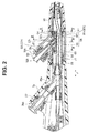
- Fig. 2 is a sectional view of a bend preventer and the operation portion taken along line II-II in Fig. 1
- Fig. 3 is a sectional view of the operation portion taken along line III-III in Fig. 2
- Fig. 4 is a sectional view of the operation portion taken along line IV-IV in Fig. 2
- Fig. 5 is a sectional view of the operation portion taken along line V-V in Fig. 2 .
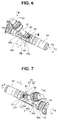
- Fig. 6 is a perspective view showing a fixing structure for a balloon pipe sleeve by removing a balloon channel side grip from the operation portion of Fig. 1 , where a branch channel connection unit for a balloon water injection channel is used;
- Fig. 7 is a perspective view of the fixing structure of Fig. 6 as viewed in a direction of VII in Fig. 6 ;
- Fig. 8 is a perspective view of the fixing structure of Fig. 6 as viewed in a direction of VIII in Fig. 6 .
- Fig. 9 is a perspective view of a connecting tube of Fig. 6 ;
- Fig. 10 is a perspective view of the branch channel connection unit of Fig. 6 ;
- Fig. 11 is a perspective view of the branch channel connection unit of Fig. 10 as viewed in a direction of XI in Fig. 10 .
- Fig. 12 is a perspective view of a pressing member in the branch channel connection unit of Fig. 10 ; and Fig. 13 is a perspective view of a block unit in the branch channel connection unit of Fig. 10 .
- an endoscope 1 includes an insertion portion 2 inserted into a subject and an operation portion 3 connected to a proximal end of the insertion portion 2 in an insertion axis direction J via a bend preventer 9.
- An ultrasound transducer unit 30 described later (see Fig. 14 ) is provided on a distal end side of the insertion portion 2 in the insertion axis direction J.
- examples of the ultrasound transducer unit 30 include an electronic radial ultrasound transducer unit which has a non-illustrated ultrasound transducer in a non-illustrated housing and a non-illustrated acoustic lens on an outer surface, where the ultrasound transducer is capable of ultrasound transmission and reception in 360-degree directions and the acoustic lens is exposed circumferentially from the housing. Also, the ultrasound transducer unit 30 is not limited to an electronic radial type.
- a balloon 90 is fitted around an outer circumference of the ultrasound transducer unit 30.
- a known ultrasound transmission medium has been injected in the balloon 90.
- a balloon channel side grip 3b and a treatment instrument insertion channel side grip 3s making up an exterior of the operation portion 3 are provided by being connected to a proximal end of the bend preventer 19 in the insertion axis direction J.
- treatment instrument insertion channel side grip 3s is connected to a proximal end of the balloon channel side grip 3b in the insertion axis direction J.
- the balloon channel side grip 3b may be rotatable relative to the treatment instrument insertion channel side grip 3s and bend preventer 19.
- various incorporated components are provided in the insertion portion 2 and operation portion 3, including a known signal cable, image guide, light guide, fluid supply conduit, and bending wire as well as an ultrasound transducer cable 40 (see Fig. 14 ) described later.
- a treatment instrument insertion channel 29 is provided in the insertion portion 2 and operation portion 3, opening at one end in a distal end of the insertion portion 2 in the insertion axis direction J and opening at another end in an after-mentioned endoscope connector 5 of the endoscope 1.
- the treatment instrument insertion channel 29 is branched in the treatment instrument insertion channel side grip 3s and the branched channel 29s is connected to a treatment instrument insertion pipe sleeve 27.
- the treatment instrument insertion pipe sleeve 27 is inserted in the treatment instrument insertion channel side grip 3s in a watertight manner through an opening 3sk formed in the treatment instrument insertion channel side grip 3s, being tilted at a predetermined angle with respect to the insertion axis direction J.
- the treatment instrument insertion pipe sleeve 27 is communicated at a first end with the treatment instrument insertion channel 29 and opens at a second end outside the operation portion 3.
- a balloon water injection channel 51 is provided in the insertion portion 2 and operation portion 3.
- the balloon water injection channel 51 is connected to and communicated with the balloon 90 provided in the insertion portion 2, and opens at another end as a first opening portion 51t in the balloon channel side grip 3b.
- the first opening portion 51t is connected to a first end portion 52i of the balloon pipe sleeve 52 through a branch channel connection unit 56 described later.
- the balloon pipe sleeve 52 is inserted in a watertight manner into the balloon channel side grip 3b through an opening 3bk formed in the balloon channel side grip 3b, by being tilted at a predetermined angle with respect to the insertion axis direction J.
- the first end portion 52i of the balloon pipe sleeve 52 is communicated with the first opening portion 51t through the branch channel connection unit 56 and a second end portion 52t opens outside the operation portion 3.
- the operator can supply the ultrasound transmission medium to the balloon 90 through the balloon pipe sleeve 52 and balloon water injection channel 51 using an after-mentioned syringe 200 (see Fig. 14 ) connected to an opening of the second end portion 52t.
- a connecting tube 50 is provided in the balloon channel side grip 3b, with the balloon water injection channel 51 passed through the connecting tube 50.
- the connecting tube 50 is designed to interconnect the bend preventer 19 and treatment instrument insertion channel side grip 3s along the insertion axis direction J, a proximal end of the connecting tube 50 in the insertion axis direction J is fixed to a distal end side of the treatment instrument insertion channel side grip 3s by a screw or the like. Note that the connecting tube 50 is detachably connected to the treatment instrument insertion channel side grip 3s.
- various incorporated components are passed through the connecting tube 50 including the above-mentioned signal cable, image guide, light guide, fluid supply conduit, bending wire, treatment instrument insertion channel 29, and ultrasound transducer cable 40 (see Fig. 14 ).
- a second opening portion 50k is formed at an intermediate position of the connecting tube 50 in the insertion axis direction J, where the second opening portion 50k exposes an interior of the connecting tube 50 outside and is communicated with the first opening portion 51t located inside the connecting tube 50 when the branch channel connection unit 56 is not connected to the first opening portion 51t.
- the second opening portion 50k has the shape of, for example, a letter L in planar shape and has an opening of a predetermined size, where the opening is used to introduce the first end portion 52i of the balloon pipe sleeve 52 and the branch channel connection unit 56 into the connecting tube 50 during assembly.
- first end portion 52i of the balloon pipe sleeve 52 is passed through the second opening portion 50k, and connected to the first opening portion 51t so as to be communicated with the first opening portion 51t when the branch channel connection unit 56 is not connected to the first opening portion 51t.
- a notch 50s is formed in the connecting tube 50, at a position different from the second opening portion 50k, exposing the interior of the connecting tube 50 to the outside and extending a predetermined length along the insertion axis direction J.
- the branch channel connection unit 56 includes a pressing member 55 and a block unit 57.
- the pressing member 55 includes a block unit positioning portion 55r and a connecting tube fixing portion 55q, where the block unit positioning portion 55r is provided with a stepped portion 55rd abutted by the block unit 57 installed consecutively with a proximal end of the block unit mounting portion 55p in the insertion axis direction while the connecting tube fixing portion 55q is shaped like an arc and installed consecutively with a proximal end of the block unit positioning portion 55r in the insertion axis direction J.
- a fixing hole 55n is formed in the connecting tube fixing portion 55q.
- the pressing member 55 is placed in the connecting tube 50 by being passed through the second opening portion 50k.
- an arc-shaped outer circumferential face of the connecting tube fixing portion 55q abuts against an inner circumferential face of the connecting tube 50 as shown in Fig. 2
- a fixing member 63 is fixed in the fixing hole 55n by being passed through the insertion hole 50n from outside of the connecting tube 50 at a position where an insertion hole 50n formed in the connecting tube 50 and the fixing hole 55n are superimposed on each other as shown in Fig. 3
- the pressing member 55 is fixed to the connecting tube 50 in a fixing area J1.
- the pressing member 55 is fixed to the connecting tube 50 only at one point by means of the fixing member 63.
- examples of the fixing member 63 include a screw.
- examples of the fixing hole 55n include a screw hole. Furthermore, the fixing member 63 allows the pressing member 55 to be detachably connected to the connecting tube 50.
- the rotation restriction portion 55d which is a member fitted in the notch 50s formed in the connecting tube 50, has a length A along the insertion axis direction J.
- the rotation restriction portion 55d is a member configured to prevent the branch channel connection unit 56 provided with the pressing member 55 fixed to the connecting tube 50 by the fixing member 63 only at one point in the fixing area J1 from being rotated in a direction R2 together with the balloon pipe sleeve 52, for example, when the insertion portion 2 is twisted with respect to the operation portion 3 or the balloon channel side grip 3b is rotated, causing the balloon pipe sleeve 52 to tilt especially in the direction R2.
- the rotation restriction portion 55d is removably inserted into the notch 50s.
- the block unit 57 is placed on the block unit mounting portion 55p.
- the block unit 57 is placed on the block unit mounting portion 55p with a proximal end of the block unit 57 in the insertion axis direction J being positioned by abutting against the stepped portion 55rd provided at a distal end of the block unit positioning portion 55r in the insertion axis direction J.
- the opening 57i is connected with the first opening portion 51t of the balloon water injection channel 51 via a connecting member 54.
- an area of the balloon water injection channel 51 on the side of the first opening portion 51t is connected via the connecting member 54 by intruding into the flow path 57r via the opening 57i.
- the connecting member 54 allows the first opening portion 51t to be detachably connected to the opening 57i.
- an inclined surface 57c is formed at the proximal end of the block unit 57 in the insertion axis direction J. Also, the inclined surface 57c is connected with the first end portion 52i of the balloon pipe sleeve 52 and is provided with a connection pipe sleeve 57e having an opening 57t of the flow path 57r. Note that the inclined surface 57c and connection pipe sleeve 57e are exposed outside the connecting tube 50 by passing through the second opening portion 50k.
- the first end portion 52i is configured to be restrained to the connection pipe sleeve 57e only by being rotated for example, after being fitted over the connection pipe sleeve 57e.
- a non-illustrated rotation stopper prevents rotation of the first end portion 52i relative to the connection pipe sleeve 57e and thus the connection made by the restraining is not broken. Note that the restraining configuration of the first end portion 52i with respect to the connection pipe sleeve 57e is not limited to this configuration.
- the block unit 57 holds the first end portion 52i in a holding area J2.
- the holding area J2 is situated forward of the fixing area J1 by being spaced away from the fixing area J1 in the insertion axis direction J.
- the block unit 57 is fixed to the pressing member 55 by the fixing member 64 by being placed on the block unit mounting portion 55p.
- the fixing member 64 allows the block unit 57 to be detachably connected to the pressing member 55. Also, the block unit 57 may be formed integrally with the pressing member 55.
- the rotation restriction portion 55d is fitted in the notch 50s and the face 57f of the block unit abuts the edge portion 50kf, even if the balloon pipe sleeve 52 is tilted in a rotation direction R, the balloon pipe sleeve 52 and the branch channel connection unit 56 are prevented from being rotated.
- a length A of the rotation restriction portion 55d in the insertion axis direction J is set to a length from the holding area J2 of the first end portion 52i of the balloon pipe sleeve 52 in the connection pipe sleeve 57e to the fixing area J1 of the pressing member 55 with respect to the connecting tube 50 by means of the fixing member 63.
- the rotation restriction portion 55d has a length A from the holding area J2 to the fixing area J1 in the insertion axis direction J as with the present embodiment, a turning force can be received over the length A from the holding area J2 to the fixing area J1, in other words, the turning force can be scattered over the length A, and thus the tilting force applied to the fixing area J1 and holding area J2 can be reduced.
- the pressing member 55 is fixed to the connecting tube 50 by the fixing member 63 at a one point in the fixing area J1 rearward of the holding area J2 in the insertion axis direction J.
- the balloon pipe sleeve 52 and branch channel connection unit 56 can be prevented from rotating using a simple configuration which will not adversely affect the aforementioned incorporated components of the connecting tube 50.
- the present embodiment uses a configuration in which the rotation restriction portion 55d is fitted in the notch 50s.
- the pressing member 55 can be assembled easily onto the connecting tube 50 simply by fitting the rotation restriction portion 55d in the notch 50s without using fixing members such as screws other than the fixing member 63, ease of assembly can be improved.
- the present invention provides the endoscope 1 which can restrict the rotation of the balloon pipe sleeve 52 and uses a simple configuration to reduce the tilting force applied to the fixing section between the balloon pipe sleeve 52 and balloon water injection channel 51 when a tilting force is applied to the balloon pipe sleeve 52.
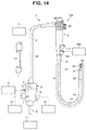
- Fig. 14 is a diagram showing an ultrasound endoscope apparatus equipped with the ultrasound endoscope of Fig. 1 .
- the ultrasound endoscope apparatus 100 includes the ultrasound endoscope 1, a light source apparatus 11, a video processor 12, an ultrasound observation apparatus 14, a suction pump 15, a water feeding tank 16, and a syringe 200.
- Principal part of the ultrasound endoscope 1 is made up of an elongated insertion portion 2, an operation portion 3, a flexible universal cord 4 extending from the operation portion 3, and an endoscope connector 5 provided on an extending end of the universal cord 4.
- the endoscope connector 5 is provided with a light source connector 6, an electrical connector 7, an ultrasound connector 8, a suction pipe sleeve 9, and an air/water feeding pipe sleeve 10.
- the light source connector 6 is configured to be detachably connected with the light source apparatus 11 configured to supply illuminating light into a subject via the light guide described above.
- the electrical connector 7 is configured to be detachably connected with the video processor 12 configured to perform various signal processing and the like via the above-mentioned image guide and signal cable.
- the ultrasound connector 8 electrically connected with a connector 45 provided on a proximal end side of the ultrasound transducer cable 40 extending out from the ultrasound transducer in the ultrasound transducer unit 30 is configured to be detachably connected with the ultrasound observation apparatus 14 via an ultrasound cable 13.
- the suction pipe sleeve 9 provided in an opening in another end of the treatment instrument insertion channel 29 is configured to be detachably connected with the suction pump 15 via a non-illustrated suction tube.
- the air/water feeding pipe sleeve 10 connected to the above-mentioned fluid supply conduit is configured to be detachably connected with the water feeding tank 16 via a non-illustrated air/water feeding tube.
- the ultrasound observation apparatus 14 is designed to perform various operation control over the ultrasound endoscope 1, including, for example, drive control of the ultrasound transducer, perform signal processing on electrical signals acquired through the drive control of the ultrasound transducer, and thereby generate a video signal.
- the video signal generated by the ultrasound observation apparatus 14 is outputted to a non-illustrated display apparatus. As a result, an ultrasound image is displayed on a screen of the display apparatus which has received the video signal.
- the insertion portion 2 of the ultrasound endoscope 1 includes a distal end portion 21, a bending portion 22 configured to be bendable, for example, in an up-and-down direction and a left-and-right direction, and a flexible tubular portion 23 having a long length and flexibility, all of which are installed consecutively.
- ultrasound transducer unit 30 and balloon 90 described above are located on a distal end side of the distal end portion 21 and fixed to the distal end portion 21.
- the operation portion 3 is provided with bending operation knobs 25 and 26 used to perform a bending operation of the bending portion 22. Also, at a position on the side of insertion portion 2, the operation portion 3 is provided with the treatment instrument insertion pipe sleeve 27 used to introduce a treatment instrument into the body through the treatment instrument insertion channel 29. Furthermore, at a position on the side of insertion portion 2, the operation portion 3 is provided with the balloon pipe sleeve 52 used to supply the ultrasound transmission medium to the balloon 90 through the balloon water injection channel 51, where the balloon pipe sleeve 52 is connectable with the syringe 200.
- the video processor 12 is designed to perform signal processing on an electrical signal transmitted from a non-illustrated image pickup unit provided in the distal end portion 21, thereby generate a standard video signal, output the video signal to a non-illustrated display apparatus, and display an endoscopic observation image on the screen of the display apparatus.
- the endoscope 1 has been described by citing an ultrasound endoscope as an example, of course, the present invention is also applicable to endoscopes other than ultrasound endoscopes.
- balloon water injection channel 51 configured to supply the ultrasound transmission medium to the balloon 90
- balloon pipe sleeve 52 connected with the syringe 200 configured to inject the ultrasound transmission medium has been cited as an example of the tubular branch channel
- the treatment instrument insertion channel 29 may be the main channel and the treatment instrument insertion pipe sleeve 27 may be a branch channel.
- a midsection of the treatment instrument insertion channel opens as a first opening portion in the balloon channel side grip 3b and the first opening portion is connected with a first end portion of the treatment instrument insertion pipe sleeve 27 via the branch channel connection unit 56.
Landscapes
- Health & Medical Sciences (AREA)
- Life Sciences & Earth Sciences (AREA)
- Surgery (AREA)
- Engineering & Computer Science (AREA)
- Veterinary Medicine (AREA)
- Public Health (AREA)
- Biomedical Technology (AREA)
- Heart & Thoracic Surgery (AREA)
- Biophysics (AREA)
- Animal Behavior & Ethology (AREA)
- General Health & Medical Sciences (AREA)
- Pathology (AREA)
- Physics & Mathematics (AREA)
- Nuclear Medicine, Radiotherapy & Molecular Imaging (AREA)
- Radiology & Medical Imaging (AREA)
- Medical Informatics (AREA)
- Molecular Biology (AREA)
- Optics & Photonics (AREA)
- Mechanical Engineering (AREA)
- Pulmonology (AREA)
- Anesthesiology (AREA)
- Hematology (AREA)
- Ultra Sonic Daignosis Equipment (AREA)
- Endoscopes (AREA)
Abstract
Description
- The present invention relates to an endoscope equipped with a branch channel communicated with a first opening portion of a main channel in an operation portion.
- A configuration in which a tubular main channel is provided inside an insertion portion or an operation portion of an endoscope is well-known, where the insertion portion is inserted into a subject and the operation portion is connected to a proximal end of the insertion portion in an insertion axis direction.
- Note that examples of the main channel include a treatment instrument insertion channel through which a treatment instrument is supplied into the subject and a balloon water injection channel through which an ultrasound transmission medium is supplied to a balloon provided in an insertion portion of an ultrasound endoscope.
- The main channel includes a first opening portion which opens in an operation portion, and the first opening portion is communicated with a first end portion of a tubular branch channel whose second end portion opens outside the operation portion.
- The branch channel is intended to supply a treatment instrument, ultrasound transmission medium, or the like to a main channel from the operation portion and is connected to the main channel in the operation portion such that the first end portion will be communicated with the first opening portion of the main channel. Note that examples of the branch channel include a treatment instrument insertion pipe sleeve and a balloon pipe sleeve connected with a syringe used to inject the ultrasound transmission medium.
- Also, Japanese Patent Application Laid-Open Publication No.
2010-207424 - Now, if a tilting force is applied to the branch channel during operation of the endoscope, a tilting force is applied to a fixing section of the branch channel as well.
- Note that cases in which the tilting force of the branch channel is applied include a case in which when the insertion portion is twisted with respect to the operation portion or when part of a grip of the operation portion provided with the branch channel is configured to be rotatable together with the branch channel, the part of the grip is rotated.
- In this case, the branch channel fixing section becomes loose, presenting a problem in that it is difficult to keep a communicating area between the first end portion of the branch channel and the first opening portion of the main channel watertight.
- Now, the configuration of Japanese Patent Application Laid-Open Publication No.
2010-207424 - The present invention has been made in view of the above problems, and has an object to provide an endoscope which can restrict rotation of a branch channel and uses a simple configuration to reduce a tilting force applied to a fixing section between a branch channel and main channel when a tilting force is applied to the branch channel.
- An endoscope according to one aspect of the present invention includes: an insertion portion inserted into a subject; an operation portion connected to a proximal end of the insertion portion in an insertion axis direction; a main channel configured to be tubular and placed in the insertion portion and in the operation portion; a first opening portion formed in the main channel and opened in the operation portion; a connecting tube configured to be passed through the main channel, provided with a second opening portion communicated with the first opening portion, and provided with a notch extending in the insertion axis direction; a branch channel configured to be tubular, where a first end portion of the branch channel is passed through the second opening portion and connected so as to be communicated with the first opening portion while a second end portion is opened outside the operation portion; a branch channel connection unit passed through the second opening portion, configured to hold the first end portion of the branch channel, and provided with a rotation restriction portion which is a protrusion fitted in the notch; and a fixing member configured to fix the branch channel connection unit to the connecting tube.
-
-
Fig. 1 is a partial perspective view schematically showing part of an insertion portion and operation portion of an endoscope according to an embodiment of the present invention; -
Fig. 2 is a sectional view of a bend preventer and the operation portion taken along line II-II inFig. 1 ; -
Fig. 3 is a sectional view of the operation portion taken along line III-III inFig. 2 ; -
Fig. 4 is a sectional view of the operation portion taken along line IV-IV inFig. 2 ; -
Fig. 5 is a sectional view of the operation portion taken along line V-V inFig. 2 ; -
Fig. 6 is a perspective view showing a fixing structure for a balloon pipe sleeve by removing a balloon channel side grip from the operation portion ofFig. 1 , where a branch channel connection unit for a balloon water injection channel is used; -
Fig. 7 is a perspective view of the fixing structure ofFig. 6 as viewed in a direction of VII inFig. 6 ; -
Fig. 8 is a perspective view of the fixing structure ofFig. 6 as viewed in a direction of VIII inFig. 6 ; -
Fig. 9 is a perspective view of a connecting tube ofFig. 6 ; -
Fig. 10 is a perspective view of the branch channel connection unit ofFig. 6 ; -
Fig. 11 is a perspective view of the branch channel connection unit ofFig. 10 as viewed in a direction of XI inFig. 10 ; -
Fig. 12 is a perspective view of a pressing member in the branch channel connection unit ofFig. 10 ; -
Fig. 13 is a perspective view of a block unit in the branch channel connection unit ofFig. 10 ; and -
Fig. 14 is a diagram showing an ultrasound endoscope apparatus equipped with an ultrasound endoscope ofFig. 1 . - Hereinafter, an embodiment of the present invention will be described with reference to the drawings. In the following description, note that the drawings in the embodiment are schematic, that a relationship between thickness and width of each component as well as ratios of the thickness among individual components are different from actual ones, and that dimensional relationships or ratios may not be uniform among the drawings.
- Note that in the present embodiment shown below, an endoscope will be described by taking an ultrasound endoscope as an example.
- Also, description will be given by citing a balloon water injection channel configured to supply an ultrasound transmission medium to a balloon provided in the insertion portion as a tubular main channel placed in an insertion portion and operation portion of the endoscope, and citing a balloon pipe sleeve connected with a syringe to inject the ultrasound transmission medium as a tubular branch channel.
-
Fig. 1 is a partial perspective view schematically showing part of an insertion portion and operation portion of an endoscope according to the present embodiment;Fig. 2 is a sectional view of a bend preventer and the operation portion taken along line II-II inFig. 1 ;Fig. 3 is a sectional view of the operation portion taken along line III-III inFig. 2 ;Fig. 4 is a sectional view of the operation portion taken along line IV-IV inFig. 2 ; andFig. 5 is a sectional view of the operation portion taken along line V-V inFig. 2 . - Also,
Fig. 6 is a perspective view showing a fixing structure for a balloon pipe sleeve by removing a balloon channel side grip from the operation portion ofFig. 1 , where a branch channel connection unit for a balloon water injection channel is used;Fig. 7 is a perspective view of the fixing structure ofFig. 6 as viewed in a direction of VII inFig. 6 ; andFig. 8 is a perspective view of the fixing structure ofFig. 6 as viewed in a direction of VIII inFig. 6 . - Furthermore,
Fig. 9 is a perspective view of a connecting tube ofFig. 6 ;Fig. 10 is a perspective view of the branch channel connection unit ofFig. 6 ; andFig. 11 is a perspective view of the branch channel connection unit ofFig. 10 as viewed in a direction of XI inFig. 10 . - Besides,
Fig. 12 is a perspective view of a pressing member in the branch channel connection unit ofFig. 10 ; andFig. 13 is a perspective view of a block unit in the branch channel connection unit ofFig. 10 . - As shown in
Fig. 1 , an endoscope 1 includes aninsertion portion 2 inserted into a subject and anoperation portion 3 connected to a proximal end of theinsertion portion 2 in an insertion axis direction J via a bend preventer 9. - An
ultrasound transducer unit 30 described later (seeFig. 14 ) is provided on a distal end side of theinsertion portion 2 in the insertion axis direction J. - Note that examples of the
ultrasound transducer unit 30 include an electronic radial ultrasound transducer unit which has a non-illustrated ultrasound transducer in a non-illustrated housing and a non-illustrated acoustic lens on an outer surface, where the ultrasound transducer is capable of ultrasound transmission and reception in 360-degree directions and the acoustic lens is exposed circumferentially from the housing. Also, theultrasound transducer unit 30 is not limited to an electronic radial type. - Also, on the distal end side of the
insertion portion 2 in the insertion axis direction J, aballoon 90 is fitted around an outer circumference of theultrasound transducer unit 30. A known ultrasound transmission medium has been injected in theballoon 90. - Also, on a distal end side of the
operation portion 3 in the insertion axis direction J, a balloonchannel side grip 3b and a treatment instrument insertionchannel side grip 3s making up an exterior of theoperation portion 3 are provided by being connected to a proximal end of thebend preventer 19 in the insertion axis direction J. - Note that the treatment instrument insertion
channel side grip 3s is connected to a proximal end of the balloonchannel side grip 3b in the insertion axis direction J. - Also, to simplify a structure of the balloon
channel side grip 3b, the balloonchannel side grip 3b may be rotatable relative to the treatment instrument insertionchannel side grip 3s andbend preventer 19. - Also, various incorporated components are provided in the
insertion portion 2 andoperation portion 3, including a known signal cable, image guide, light guide, fluid supply conduit, and bending wire as well as an ultrasound transducer cable 40 (seeFig. 14 ) described later. - Here, as shown in
Fig. 2 a treatmentinstrument insertion channel 29 is provided in theinsertion portion 2 andoperation portion 3, opening at one end in a distal end of theinsertion portion 2 in the insertion axis direction J and opening at another end in an after-mentionedendoscope connector 5 of the endoscope 1. - As shown in
Fig. 2 , the treatmentinstrument insertion channel 29 is branched in the treatment instrument insertionchannel side grip 3s and thebranched channel 29s is connected to a treatment instrumentinsertion pipe sleeve 27. - The treatment instrument
insertion pipe sleeve 27 is inserted in the treatment instrument insertionchannel side grip 3s in a watertight manner through an opening 3sk formed in the treatment instrument insertionchannel side grip 3s, being tilted at a predetermined angle with respect to the insertion axis direction J. - Also, the treatment instrument
insertion pipe sleeve 27 is communicated at a first end with the treatmentinstrument insertion channel 29 and opens at a second end outside theoperation portion 3. - Consequently, after inserting a treatment instrument into the treatment instrument
insertion pipe sleeve 27 through an opening in the second end of the treatment instrumentinsertion pipe sleeve 27, an operator can cause the treatment instrument to pass through the treatmentinstrument insertion channel 29 and to protrude from the distal end of theinsertion portion 2 in the insertion axis direction J. - Also, as shown in
Fig. 2 , a balloonwater injection channel 51 is provided in theinsertion portion 2 andoperation portion 3. - At one end, the balloon
water injection channel 51 is connected to and communicated with theballoon 90 provided in theinsertion portion 2, and opens at another end as a first openingportion 51t in the balloonchannel side grip 3b. - The first opening
portion 51t is connected to afirst end portion 52i of theballoon pipe sleeve 52 through a branchchannel connection unit 56 described later. - The
balloon pipe sleeve 52 is inserted in a watertight manner into the balloonchannel side grip 3b through an opening 3bk formed in the balloonchannel side grip 3b, by being tilted at a predetermined angle with respect to the insertion axis direction J. - The
first end portion 52i of theballoon pipe sleeve 52 is communicated with the first openingportion 51t through the branchchannel connection unit 56 and asecond end portion 52t opens outside theoperation portion 3. - Consequently, the operator can supply the ultrasound transmission medium to the
balloon 90 through theballoon pipe sleeve 52 and balloonwater injection channel 51 using an after-mentioned syringe 200 (seeFig. 14 ) connected to an opening of thesecond end portion 52t. - Also, as shown in
Figs. 2 to 9 , aconnecting tube 50 is provided in the balloonchannel side grip 3b, with the balloonwater injection channel 51 passed through theconnecting tube 50. - The connecting
tube 50 is designed to interconnect thebend preventer 19 and treatment instrument insertionchannel side grip 3s along the insertion axis direction J, a proximal end of the connectingtube 50 in the insertion axis direction J is fixed to a distal end side of the treatment instrument insertionchannel side grip 3s by a screw or the like. Note that the connectingtube 50 is detachably connected to the treatment instrument insertionchannel side grip 3s. - Also, in addition to the balloon
water injection channel 51, various incorporated components are passed through the connectingtube 50 including the above-mentioned signal cable, image guide, light guide, fluid supply conduit, bending wire, treatmentinstrument insertion channel 29, and ultrasound transducer cable 40 (seeFig. 14 ). - Also, as shown in
Figs. 2 ,6 ,7 , and9 , asecond opening portion 50k is formed at an intermediate position of the connectingtube 50 in the insertion axis direction J, where thesecond opening portion 50k exposes an interior of the connectingtube 50 outside and is communicated with thefirst opening portion 51t located inside the connectingtube 50 when the branchchannel connection unit 56 is not connected to thefirst opening portion 51t. - As shown in
Fig. 9 , thesecond opening portion 50k has the shape of, for example, a letter L in planar shape and has an opening of a predetermined size, where the opening is used to introduce thefirst end portion 52i of theballoon pipe sleeve 52 and the branchchannel connection unit 56 into the connectingtube 50 during assembly. - Note that the
first end portion 52i of theballoon pipe sleeve 52 is passed through thesecond opening portion 50k, and connected to thefirst opening portion 51t so as to be communicated with thefirst opening portion 51t when the branchchannel connection unit 56 is not connected to thefirst opening portion 51t. - Also, as shown in
Figs. 7 and8 , anotch 50s is formed in the connectingtube 50, at a position different from thesecond opening portion 50k, exposing the interior of the connectingtube 50 to the outside and extending a predetermined length along the insertion axis direction J. - As shown in
Figs. 2 ,10, and 11 , the branchchannel connection unit 56 includes a pressingmember 55 and ablock unit 57. - As shown in
Fig. 12 , the pressingmember 55 includes a blockunit mounting portion 55p located on a distal end side in the insertion axis direction J and a blockunit fixing portion 55w standing up from an end portion of the blockunit mounting portion 55p in a direction Q orthogonal to the insertion axis direction J. - Also, the pressing
member 55 includes a blockunit positioning portion 55r and a connectingtube fixing portion 55q, where the blockunit positioning portion 55r is provided with a stepped portion 55rd abutted by theblock unit 57 installed consecutively with a proximal end of the blockunit mounting portion 55p in the insertion axis direction while the connectingtube fixing portion 55q is shaped like an arc and installed consecutively with a proximal end of the blockunit positioning portion 55r in the insertion axis direction J. - As shown in
Figs. 10 to 12 , a fixinghole 55n is formed in the connectingtube fixing portion 55q. - The pressing
member 55 is placed in the connectingtube 50 by being passed through thesecond opening portion 50k. When an arc-shaped outer circumferential face of the connectingtube fixing portion 55q abuts against an inner circumferential face of the connectingtube 50 as shown inFig. 2 , if a fixingmember 63 is fixed in the fixinghole 55n by being passed through theinsertion hole 50n from outside of the connectingtube 50 at a position where aninsertion hole 50n formed in the connectingtube 50 and the fixinghole 55n are superimposed on each other as shown inFig. 3 , the pressingmember 55 is fixed to the connectingtube 50 in a fixing area J1. - Note that in the fixing area J1, the pressing
member 55 is fixed to the connectingtube 50 only at one point by means of the fixingmember 63. - This is because if plural fixing points with respect to the connecting
tube 50 are provided on the pressingmember 55, plural fixing members become prone to interference with the aforementioned various incorporated components passed through the connectingtube 50 and adversely affect each of the incorporated components, and thus it is inevitable to provide a minimum number of fixing point-one fixing point--on the pressingmember 55 with respect to the connectingtube 50 by avoiding thesecond opening portion 50k and notch 50s. - Also, examples of the fixing
member 63 include a screw. Thus, examples of the fixinghole 55n include a screw hole. Furthermore, the fixingmember 63 allows the pressingmember 55 to be detachably connected to the connectingtube 50. - Also, as shown in
Figs. 10 to 12 , in that end portion of the pressingmember 55 in the direction Q which is opposite the end portion from which the blockunit fixing portion 55w stands up, arotation restriction portion 55d is formed, extending outward in the direction Q. Note that therotation restriction portion 55d is, for example, tabular in shape. - As shown in
Fig. 8 , therotation restriction portion 55d, which is a member fitted in thenotch 50s formed in the connectingtube 50, has a length A along the insertion axis direction J. - Being fitted in the
notch 50s, therotation restriction portion 55d is a member configured to prevent the branchchannel connection unit 56 provided with the pressingmember 55 fixed to the connectingtube 50 by the fixingmember 63 only at one point in the fixing area J1 from being rotated in a direction R2 together with theballoon pipe sleeve 52, for example, when theinsertion portion 2 is twisted with respect to theoperation portion 3 or the balloonchannel side grip 3b is rotated, causing theballoon pipe sleeve 52 to tilt especially in the direction R2. Note that therotation restriction portion 55d is removably inserted into thenotch 50s. - In the connecting
tube 50, theblock unit 57 is placed on the blockunit mounting portion 55p. - The
block unit 57 is placed on the blockunit mounting portion 55p with a proximal end of theblock unit 57 in the insertion axis direction J being positioned by abutting against the stepped portion 55rd provided at a distal end of the blockunit positioning portion 55r in the insertion axis direction J. - As shown in
Fig. 2 , aflow path 57r is formed in theblock unit 57, extending from a distal end to a proximal end in the insertion axis direction J. As shown inFig. 13 , anopening 57i of theflow path 57r is formed at the distal end of theblock unit 57 in the insertion axis direction J. - As shown in
Figs. 2 and5 to 7 , in the connectingtube 50, theopening 57i is connected with thefirst opening portion 51t of the balloonwater injection channel 51 via a connectingmember 54. - Specifically, an area of the balloon
water injection channel 51 on the side of thefirst opening portion 51t is connected via the connectingmember 54 by intruding into theflow path 57r via theopening 57i. Note that the connectingmember 54 allows thefirst opening portion 51t to be detachably connected to theopening 57i. - Also, as shown in
Fig. 13 , aninclined surface 57c is formed at the proximal end of theblock unit 57 in the insertion axis direction J. Also, theinclined surface 57c is connected with thefirst end portion 52i of theballoon pipe sleeve 52 and is provided with aconnection pipe sleeve 57e having an opening 57t of theflow path 57r. Note that theinclined surface 57c andconnection pipe sleeve 57e are exposed outside the connectingtube 50 by passing through thesecond opening portion 50k. - Regarding connection of the
first end portion 52i to theconnection pipe sleeve 57e, thefirst end portion 52i is configured to be restrained to theconnection pipe sleeve 57e only by being rotated for example, after being fitted over theconnection pipe sleeve 57e. - After the restraining, a non-illustrated rotation stopper prevents rotation of the
first end portion 52i relative to theconnection pipe sleeve 57e and thus the connection made by the restraining is not broken. Note that the restraining configuration of thefirst end portion 52i with respect to theconnection pipe sleeve 57e is not limited to this configuration. - In this way, as the
first end portion 52i of theballoon pipe sleeve 52 is restrained to theconnection pipe sleeve 57e, theblock unit 57, holds thefirst end portion 52i in a holding area J2. Note that the holding area J2 is situated forward of the fixing area J1 by being spaced away from the fixing area J1 in the insertion axis direction J. - Also, that
face 57h of theblock unit 57 which is opposed to the blockunit fixing portion 55w in the direction Q abuts against the blockunit fixing portion 55w passed through aninsertion hole 55m formed in the blockunit fixing portion 55w as shown inFig. 12 , fixed by a fixingmember 64 as shown inFigs. 4 ,6 , and11 , and thereby fixed to the pressingmember 55. Note that examples of the fixingmember 64 include a screw. - Consequently, the
block unit 57 is fixed to the pressingmember 55 by the fixingmember 64 by being placed on the blockunit mounting portion 55p. - Note that the fixing
member 64 allows theblock unit 57 to be detachably connected to the pressingmember 55. Also, theblock unit 57 may be formed integrally with the pressingmember 55. - Furthermore, as shown in
Figs. 6 and 7 , aface 57f of theblock unit 57 opposed to theface 57h in the direction Q abuts an edge portion 50kf of thesecond opening portion 50k shown inFig. 9 and thereby prevents the branchchannel connection unit 56 provided with the pressingmember 55 fixed to the connectingtube 50 by the fixingmember 63 only at one point in the fixing area J1 from being rotated in a direction R1 together with theballoon pipe sleeve 52, for example, when theinsertion portion 2 is twisted with respect to theoperation portion 3 or the balloonchannel side grip 3b is rotated, causing theballoon pipe sleeve 52 to tilt in the direction R1. - That is, even if the
rotation restriction portion 55d is not fitted in thenotch 50s, the abutment of theface 57f against the edge portion 50kf prevents the branchchannel connection unit 56 from being rotated in the direction R1 together with theballoon pipe sleeve 52. - Note that by being fitted in the
notch 50s, therotation restriction portion 55d also prevents the branchchannel connection unit 56 from being rotated in the direction R1 together with theballoon pipe sleeve 52 when theballoon pipe sleeve 52 is tilted in the direction R1. - Thus, according to the present embodiment, since the
rotation restriction portion 55d is fitted in thenotch 50s and theface 57f of the block unit abuts the edge portion 50kf, even if theballoon pipe sleeve 52 is tilted in a rotation direction R, theballoon pipe sleeve 52 and the branchchannel connection unit 56 are prevented from being rotated. - This reduces a tilting force applied to the fixing area J1 in which the pressing
member 55 is fixed to the connectingtube 50 only at one point by means of the fixingmember 63, i.e., a tilting force applied to the branchchannel connection unit 56 even when theballoon pipe sleeve 52 is tilted in the rotation direction R. Thus, tilting forces applied to a connecting area of thefirst end portion 52i with respect to theconnection pipe sleeve 57e and a connecting area of thefirst opening portion 51t with respect to theopening 57i are reduced, thereby providing a configuration which sufficiently ensures water tightness of each of the connecting areas. - Now, as shown in
Figs. 7 ,8 , and10 to 12 , a length A of therotation restriction portion 55d in the insertion axis direction J is set to a length from the holding area J2 of thefirst end portion 52i of theballoon pipe sleeve 52 in theconnection pipe sleeve 57e to the fixing area J1 of the pressingmember 55 with respect to the connectingtube 50 by means of the fixingmember 63. - This is because since the pressing
member 55 is fixed to the connectingtube 50 by the fixingmember 63 at one point in the fixing area J1 rearward of thesecond opening portion 50k in the insertion axis direction J as described above, when therotation restriction portion 55d is fitted in thenotch 50s from the holding area J2 to the fixing area J1 in the insertion axis direction J, the tilting force in the rotation direction R can be received by a fitting area of therotation restriction portion 55d in thenotch 50s over the entire length A. - That is, suppose the
rotation restriction portion 55d is shorter than the length A and fitted in anotch 50s with a similar notch width, only around the holding area J2, if a tilting force is applied to theballoon pipe sleeve 52 in the rotation direction R, although rotation of the branchchannel connection unit 56 can be prevented, the tilting force is concentrated on the holding area J2, making it difficult to keep the holding area J2 watertight. - However, if the
rotation restriction portion 55d has a length A from the holding area J2 to the fixing area J1 in the insertion axis direction J as with the present embodiment, a turning force can be received over the length A from the holding area J2 to the fixing area J1, in other words, the turning force can be scattered over the length A, and thus the tilting force applied to the fixing area J1 and holding area J2 can be reduced. - Thus, in the present embodiment, it has been shown that the
rotation restriction portion 55d formed on the pressingmember 55 of the branchchannel connection unit 56 used for connection between thefirst end portion 52i of theballoon pipe sleeve 52 and thefirst opening portion 51t of the balloonwater injection channel 51 is fitted in thenotch 50s formed in the connectingtube 50. - Also, it has been shown that the pressing
member 55 is fixed to the connectingtube 50 by the fixingmember 63 at a one point in the fixing area J1 rearward of the holding area J2 in the insertion axis direction J. - Consequently, even if a tilting force is applied to the
balloon pipe sleeve 52 in the rotation direction R, theballoon pipe sleeve 52 and branchchannel connection unit 56 can be prevented from rotating using a simple configuration which will not adversely affect the aforementioned incorporated components of the connectingtube 50. - This makes it possible to reduce the tilting force in the rotation direction R applied even to a connecting portion between the
first opening portion 51t of the balloonwater injection channel 51 and thefirst end portion 52i of theballoon pipe sleeve 52, i.e., a connecting portion between theconnection pipe sleeve 57e of theblock unit 57 and thefirst end portion 52i of theballoon pipe sleeve 52 and a connecting portion between theopening 57i of theblock unit 57 and thefirst opening portion 51t. - As described above, in a configuration in which the pressing
member 55 is fixed to the connectingtube 50 by the fixingmember 63 at one point in the fixing area J1, since the branchchannel connection unit 56 is not fixed near the holding area J2 of thefirst end portion 52i with respect to theconnection pipe sleeve 57e, the tilting force in the rotation direction R tends to be applied to the fixing area J1 in a concentrated manner when theballoon pipe sleeve 52 is tilted in the rotation direction R. However, as described above, when interference with the incorporated components of the connectingtube 50 is taken into consideration, a fixing member configured to fix the pressingmember 55 directly to the connectingtube 50 cannot be provided near the holding area J2. Thus, instead of a fixing member, the present embodiment uses a configuration in which therotation restriction portion 55d is fitted in thenotch 50s. - Consequently, even if a tilting force is applied to the
balloon pipe sleeve 52 in the rotation direction R, a simple configuration in which merely therotation restriction portion 55d is fitted in thenotch 50s can sufficiently ensure water tightness of the connecting portion between theconnection pipe sleeve 57e of theblock unit 57 and thefirst end portion 52i of theballoon pipe sleeve 52 as well as the connecting portion between theopening 57i of theblock unit 57 and thefirst opening portion 51t. - Also, it has been shown that in the insertion axis direction J, the
rotation restriction portion 55d is fitted in thenotch 50s over a fitting length corresponding to the length A from the fixing area J1 to the holding area J2 described above. - Consequently, the tilting force applied to the
balloon pipe sleeve 52 and branchchannel connection unit 56 in the rotation direction R can be scattered over the length A, making it possible to sufficiently ensure water tightness of the connecting portion with thefirst end portion 52i of theballoon pipe sleeve 52 as well as the connecting portion between theopening 57i of theblock unit 57 and the first opening portion 51f. - Also, since the pressing
member 55 can be assembled easily onto the connectingtube 50 simply by fitting therotation restriction portion 55d in thenotch 50s without using fixing members such as screws other than the fixingmember 63, ease of assembly can be improved. - Thus, the present invention provides the endoscope 1 which can restrict the rotation of the
balloon pipe sleeve 52 and uses a simple configuration to reduce the tilting force applied to the fixing section between theballoon pipe sleeve 52 and balloonwater injection channel 51 when a tilting force is applied to theballoon pipe sleeve 52. - Now an exemplary configuration of the ultrasound endoscope 1 used in the present embodiment will be described below with reference to
Fig. 14. Fig. 14 is a diagram showing an ultrasound endoscope apparatus equipped with the ultrasound endoscope ofFig. 1 . - As shown in
Fig. 14 , theultrasound endoscope apparatus 100 includes the ultrasound endoscope 1, alight source apparatus 11, avideo processor 12, anultrasound observation apparatus 14, asuction pump 15, awater feeding tank 16, and asyringe 200. - Principal part of the ultrasound endoscope 1 is made up of an
elongated insertion portion 2, anoperation portion 3, a flexibleuniversal cord 4 extending from theoperation portion 3, and anendoscope connector 5 provided on an extending end of theuniversal cord 4. - The
endoscope connector 5 is provided with alight source connector 6, anelectrical connector 7, anultrasound connector 8, a suction pipe sleeve 9, and an air/waterfeeding pipe sleeve 10. - The
light source connector 6 is configured to be detachably connected with thelight source apparatus 11 configured to supply illuminating light into a subject via the light guide described above. - Also, the
electrical connector 7 is configured to be detachably connected with thevideo processor 12 configured to perform various signal processing and the like via the above-mentioned image guide and signal cable. - Furthermore, the
ultrasound connector 8 electrically connected with aconnector 45 provided on a proximal end side of theultrasound transducer cable 40 extending out from the ultrasound transducer in theultrasound transducer unit 30 is configured to be detachably connected with theultrasound observation apparatus 14 via anultrasound cable 13. - Also, the suction pipe sleeve 9 provided in an opening in another end of the treatment
instrument insertion channel 29 is configured to be detachably connected with thesuction pump 15 via a non-illustrated suction tube. Furthermore, the air/waterfeeding pipe sleeve 10 connected to the above-mentioned fluid supply conduit is configured to be detachably connected with thewater feeding tank 16 via a non-illustrated air/water feeding tube. - The
ultrasound observation apparatus 14 is designed to perform various operation control over the ultrasound endoscope 1, including, for example, drive control of the ultrasound transducer, perform signal processing on electrical signals acquired through the drive control of the ultrasound transducer, and thereby generate a video signal. - Note that the video signal generated by the
ultrasound observation apparatus 14 is outputted to a non-illustrated display apparatus. As a result, an ultrasound image is displayed on a screen of the display apparatus which has received the video signal. - Starting from the distal end side, the
insertion portion 2 of the ultrasound endoscope 1 includes adistal end portion 21, a bendingportion 22 configured to be bendable, for example, in an up-and-down direction and a left-and-right direction, and a flexibletubular portion 23 having a long length and flexibility, all of which are installed consecutively. - Note that the
ultrasound transducer unit 30 andballoon 90 described above are located on a distal end side of thedistal end portion 21 and fixed to thedistal end portion 21. - The
operation portion 3 is provided with bending operation knobs 25 and 26 used to perform a bending operation of the bendingportion 22. Also, at a position on the side ofinsertion portion 2, theoperation portion 3 is provided with the treatment instrumentinsertion pipe sleeve 27 used to introduce a treatment instrument into the body through the treatmentinstrument insertion channel 29. Furthermore, at a position on the side ofinsertion portion 2, theoperation portion 3 is provided with theballoon pipe sleeve 52 used to supply the ultrasound transmission medium to theballoon 90 through the balloonwater injection channel 51, where theballoon pipe sleeve 52 is connectable with thesyringe 200. - The
video processor 12 is designed to perform signal processing on an electrical signal transmitted from a non-illustrated image pickup unit provided in thedistal end portion 21, thereby generate a standard video signal, output the video signal to a non-illustrated display apparatus, and display an endoscopic observation image on the screen of the display apparatus. - Note that the configuration of the ultrasound endoscope 1 described above is strictly exemplary and, of course, is not limited to the configuration of
Fig. 14 . - Also, although in the present embodiment described above, the endoscope 1 has been described by citing an ultrasound endoscope as an example, of course, the present invention is also applicable to endoscopes other than ultrasound endoscopes.
- Furthermore, although the balloon
water injection channel 51 configured to supply the ultrasound transmission medium to theballoon 90 has been cited as an example of the tubular main channel and theballoon pipe sleeve 52 connected with thesyringe 200 configured to inject the ultrasound transmission medium has been cited as an example of the tubular branch channel, this is not restrictive and, needless to say, other conduits may be used as well. - Regarding the other conduits, for example, the treatment
instrument insertion channel 29 may be the main channel and the treatment instrumentinsertion pipe sleeve 27 may be a branch channel. In that case, a midsection of the treatment instrument insertion channel opens as a first opening portion in the balloonchannel side grip 3b and the first opening portion is connected with a first end portion of the treatment instrumentinsertion pipe sleeve 27 via the branchchannel connection unit 56. - The present application is based upon and claims the benefit of priority from Japanese Patent Application No.
2014-147067
Claims (3)
- An endoscope comprising:an insertion portion inserted into a subject;an operation portion connected to a proximal end of the insertion portion in an insertion axis direction;a main channel configured to be tubular and placed in the insertion portion and in the operation portion;a first opening portion formed in the main channel and opened in the operation portion;a connecting tube configured to be passed through the main channel, provided with a second opening portion communicated with the first opening portion, and provided with a notch extending in the insertion axis direction;a branch channel configured to be tubular, where a first end portion of the branch channel is passed through the second opening portion and connected so as to be communicated with the first opening portion while a second end portion is opened outside the operation portion;a branch channel connection unit passed through the second opening portion, configured to hold the first end portion of the branch channel, and provided with a rotation restriction portion which is a protrusion fitted in the notch; anda fixing member configured to fix the branch channel connection unit to the connecting tube.
- The endoscope according to claim 1, wherein the branch channel connection unit comprises:a pressing member fixed to the connecting tube by the fixing member and provided with the rotation restriction portion; anda block unit fixed to the pressing member and configured to restrain the first end portion of the branch channel.
- The endoscope according to claim 1 or 2, wherein:a fixing area in which the branch channel connection unit is fixed to the connecting tube by the fixing member is spaced away from a holding area of the first end portion of the branch channel on the branch channel connection unit toward a proximal end in the insertion axis direction; andthe rotation restriction portion fitted in the notch extends from the holding area to the fixing area in the insertion axis direction.
Applications Claiming Priority (2)
| Application Number | Priority Date | Filing Date | Title |
|---|---|---|---|
| JP2014147067 | 2014-07-17 | ||
| PCT/JP2015/061631 WO2016009690A1 (en) | 2014-07-17 | 2015-04-15 | Endoscope |
Publications (2)
| Publication Number | Publication Date |
|---|---|
| EP3050489A1 true EP3050489A1 (en) | 2016-08-03 |
| EP3050489A4 EP3050489A4 (en) | 2017-07-05 |
Family
ID=55078195
Family Applications (1)
| Application Number | Title | Priority Date | Filing Date |
|---|---|---|---|
| EP15822187.9A Withdrawn EP3050489A4 (en) | 2014-07-17 | 2015-04-15 | Endoscope |
Country Status (5)
| Country | Link |
|---|---|
| US (1) | US9782058B2 (en) |
| EP (1) | EP3050489A4 (en) |
| JP (1) | JP5893812B1 (en) |
| CN (1) | CN105722449B (en) |
| WO (1) | WO2016009690A1 (en) |
Families Citing this family (4)
| Publication number | Priority date | Publication date | Assignee | Title |
|---|---|---|---|---|
| DE102016201905A1 (en) * | 2016-02-09 | 2017-08-10 | Olympus Winter & Ibe Gmbh | Surgical instrument and method of manufacturing a surgical instrument |
| WO2017168762A1 (en) * | 2016-03-31 | 2017-10-05 | オリンパス株式会社 | Treatment tool for endoscopes |
| CN115397299A (en) * | 2020-02-04 | 2022-11-25 | 波士顿科学国际有限公司 | rotatable medical device |
| EP4183310A1 (en) * | 2021-11-23 | 2023-05-24 | Ambu A/S | Endoscope comprising a y-connector having a curved instrument insertion channel |
Family Cites Families (17)
| Publication number | Priority date | Publication date | Assignee | Title |
|---|---|---|---|---|
| EP0100977B1 (en) * | 1982-08-09 | 1988-01-20 | Olympus Optical Co., Ltd. | Endoscope |
| JPH0628628B2 (en) * | 1985-05-20 | 1994-04-20 | オリンパス光学工業株式会社 | Endoscope |
| DE3636028A1 (en) | 1985-10-25 | 1987-04-30 | Olympus Optical Co | ENDOSCOPE |
| JPS62102732A (en) * | 1985-10-30 | 1987-05-13 | オリンパス光学工業株式会社 | Endoscope |
| JPS6335226A (en) * | 1986-07-30 | 1988-02-15 | オリンパス光学工業株式会社 | Endoscope |
| US4750477A (en) * | 1987-02-20 | 1988-06-14 | Circon Corporation | Instrument control head |
| JPH065761Y2 (en) * | 1988-04-25 | 1994-02-16 | 旭光学工業株式会社 | Endoscope |
| US5735793A (en) * | 1995-01-12 | 1998-04-07 | Olympus Optical Co., Ltd. | Endoscope |
| JP3070032B2 (en) * | 1995-02-14 | 2000-07-24 | 富士写真光機株式会社 | Endoscope hand operation structure |
| US5810718A (en) * | 1997-02-14 | 1998-09-22 | Fuji Photo Optical Co., Ltd. | Coupler structure for tube units of endoscopes |
| JP4207626B2 (en) * | 2003-03-28 | 2009-01-14 | フジノン株式会社 | Endoscope |
| DE102005039601A1 (en) * | 2005-08-19 | 2007-02-22 | Karl Storz Gmbh & Co. Kg | Endoscope, especially duodenoscope for mother-baby cholangioscopy |
| DE602006006131D1 (en) * | 2005-10-17 | 2009-05-20 | Olympus Medical Systems Corp | endoscope |
| JP2010207424A (en) * | 2009-03-11 | 2010-09-24 | Hoya Corp | Structure of treatment instrument insertion part of endoscope |
| CN102781302B (en) * | 2010-07-05 | 2015-05-06 | 奥林巴斯医疗株式会社 | Endoscopic tubes and endoscopic devices |
| JP5296952B1 (en) * | 2011-11-25 | 2013-09-25 | オリンパスメディカルシステムズ株式会社 | Endoscope |
| JP5860693B2 (en) * | 2011-12-26 | 2016-02-16 | オリンパス株式会社 | Endoscope |
-
2015
- 2015-04-15 JP JP2015544269A patent/JP5893812B1/en active Active
- 2015-04-15 EP EP15822187.9A patent/EP3050489A4/en not_active Withdrawn
- 2015-04-15 WO PCT/JP2015/061631 patent/WO2016009690A1/en not_active Ceased
- 2015-04-15 CN CN201580002634.3A patent/CN105722449B/en active Active
-
2016
- 2016-05-09 US US15/149,251 patent/US9782058B2/en active Active
Also Published As
| Publication number | Publication date |
|---|---|
| EP3050489A4 (en) | 2017-07-05 |
| CN105722449B (en) | 2018-07-06 |
| US9782058B2 (en) | 2017-10-10 |
| JP5893812B1 (en) | 2016-03-23 |
| WO2016009690A1 (en) | 2016-01-21 |
| US20160249792A1 (en) | 2016-09-01 |
| JPWO2016009690A1 (en) | 2017-04-27 |
| CN105722449A (en) | 2016-06-29 |
Similar Documents
| Publication | Publication Date | Title |
|---|---|---|
| EP1247484B1 (en) | Endoscope with observation window cleaning device | |
| US20090177038A1 (en) | Electronic endoscope | |
| US20190150722A1 (en) | Washing tool and endoscope system | |
| EP3050489A1 (en) | Endoscope | |
| US20200281446A1 (en) | Endoscope | |
| JP2006034628A (en) | Endoscope | |
| CN101292856A (en) | medical device | |
| US20070027360A1 (en) | Endoscope | |
| JP6594151B2 (en) | Ultrasound endoscope | |
| WO2018230274A1 (en) | Endoscope | |
| US20170143298A1 (en) | Ultrasound endoscope | |
| CN106604673B (en) | Endoscope | |
| US9974517B2 (en) | Ultrasound endoscope | |
| US10898058B2 (en) | Endoscope having cover and molded member each forming part of distal end face of insertion section | |
| CN107710045B (en) | Lens assemblies and endoscopes for endoscopes | |
| CN107205620B (en) | Front end cover for endoscope | |
| WO2015198641A1 (en) | Endoscopic system | |
| JP5992948B2 (en) | Endoscope | |
| CN111065309B (en) | Insertion part of endoscope | |
| EP3219246A1 (en) | Dialing unit and introduction device | |
| JP6779810B2 (en) | Endoscope and endoscope system | |
| JP6103953B2 (en) | Endoscope system | |
| JP2005168767A (en) | Endoscope and manufacturing method of the same |
Legal Events
| Date | Code | Title | Description |
|---|---|---|---|
| PUAI | Public reference made under article 153(3) epc to a published international application that has entered the european phase |
Free format text: ORIGINAL CODE: 0009012 |
|
| 17P | Request for examination filed |
Effective date: 20160427 |
|
| AK | Designated contracting states |
Kind code of ref document: A1 Designated state(s): AL AT BE BG CH CY CZ DE DK EE ES FI FR GB GR HR HU IE IS IT LI LT LU LV MC MK MT NL NO PL PT RO RS SE SI SK SM TR |
|
| AX | Request for extension of the european patent |
Extension state: BA ME |
|
| RAP1 | Party data changed (applicant data changed or rights of an application transferred) |
Owner name: OLYMPUS CORPORATION |
|
| RAP1 | Party data changed (applicant data changed or rights of an application transferred) |
Owner name: OLYMPUS CORPORATION |
|
| RIN1 | Information on inventor provided before grant (corrected) |
Inventor name: OGAWA, TOMOAKI |
|
| A4 | Supplementary search report drawn up and despatched |
Effective date: 20170606 |
|
| RIC1 | Information provided on ipc code assigned before grant |
Ipc: A61B 8/12 20060101ALI20170530BHEP Ipc: A61B 1/00 20060101AFI20170530BHEP |
|
| DAV | Request for validation of the european patent (deleted) | ||
| DAX | Request for extension of the european patent (deleted) | ||
| STAA | Information on the status of an ep patent application or granted ep patent |
Free format text: STATUS: EXAMINATION IS IN PROGRESS |
|
| 17Q | First examination report despatched |
Effective date: 20200408 |
|
| STAA | Information on the status of an ep patent application or granted ep patent |
Free format text: STATUS: THE APPLICATION IS DEEMED TO BE WITHDRAWN |
|
| 18D | Application deemed to be withdrawn |
Effective date: 20200819 |