EP3050342B1 - Method for testing a wireless link of a wi-fi node, and circuit performing the method - Google Patents
Method for testing a wireless link of a wi-fi node, and circuit performing the method Download PDFInfo
- Publication number
- EP3050342B1 EP3050342B1 EP14776654.7A EP14776654A EP3050342B1 EP 3050342 B1 EP3050342 B1 EP 3050342B1 EP 14776654 A EP14776654 A EP 14776654A EP 3050342 B1 EP3050342 B1 EP 3050342B1
- Authority
- EP
- European Patent Office
- Prior art keywords
- wireless link
- cpe
- samples
- wireless
- rate
- Prior art date
- Legal status (The legal status is an assumption and is not a legal conclusion. Google has not performed a legal analysis and makes no representation as to the accuracy of the status listed.)
- Active
Links
Images




Classifications
-
- H—ELECTRICITY
- H04—ELECTRIC COMMUNICATION TECHNIQUE
- H04L—TRANSMISSION OF DIGITAL INFORMATION, e.g. TELEGRAPHIC COMMUNICATION
- H04L43/00—Arrangements for monitoring or testing data switching networks
- H04L43/08—Monitoring or testing based on specific metrics, e.g. QoS, energy consumption or environmental parameters
- H04L43/0876—Network utilisation, e.g. volume of load or congestion level
- H04L43/0894—Packet rate
-
- H—ELECTRICITY
- H04—ELECTRIC COMMUNICATION TECHNIQUE
- H04L—TRANSMISSION OF DIGITAL INFORMATION, e.g. TELEGRAPHIC COMMUNICATION
- H04L41/00—Arrangements for maintenance, administration or management of data switching networks, e.g. of packet switching networks
- H04L41/14—Network analysis or design
- H04L41/142—Network analysis or design using statistical or mathematical methods
-
- H—ELECTRICITY
- H04—ELECTRIC COMMUNICATION TECHNIQUE
- H04L—TRANSMISSION OF DIGITAL INFORMATION, e.g. TELEGRAPHIC COMMUNICATION
- H04L43/00—Arrangements for monitoring or testing data switching networks
- H04L43/04—Processing captured monitoring data, e.g. for logfile generation
- H04L43/045—Processing captured monitoring data, e.g. for logfile generation for graphical visualisation of monitoring data
-
- H—ELECTRICITY
- H04—ELECTRIC COMMUNICATION TECHNIQUE
- H04L—TRANSMISSION OF DIGITAL INFORMATION, e.g. TELEGRAPHIC COMMUNICATION
- H04L43/00—Arrangements for monitoring or testing data switching networks
- H04L43/08—Monitoring or testing based on specific metrics, e.g. QoS, energy consumption or environmental parameters
- H04L43/0876—Network utilisation, e.g. volume of load or congestion level
- H04L43/0888—Throughput
-
- H—ELECTRICITY
- H04—ELECTRIC COMMUNICATION TECHNIQUE
- H04L—TRANSMISSION OF DIGITAL INFORMATION, e.g. TELEGRAPHIC COMMUNICATION
- H04L43/00—Arrangements for monitoring or testing data switching networks
- H04L43/12—Network monitoring probes
-
- H—ELECTRICITY
- H04—ELECTRIC COMMUNICATION TECHNIQUE
- H04L—TRANSMISSION OF DIGITAL INFORMATION, e.g. TELEGRAPHIC COMMUNICATION
- H04L43/00—Arrangements for monitoring or testing data switching networks
- H04L43/16—Threshold monitoring
-
- H—ELECTRICITY
- H04—ELECTRIC COMMUNICATION TECHNIQUE
- H04W—WIRELESS COMMUNICATION NETWORKS
- H04W24/00—Supervisory, monitoring or testing arrangements
- H04W24/04—Arrangements for maintaining operational condition
-
- H—ELECTRICITY
- H04—ELECTRIC COMMUNICATION TECHNIQUE
- H04W—WIRELESS COMMUNICATION NETWORKS
- H04W24/00—Supervisory, monitoring or testing arrangements
- H04W24/06—Testing, supervising or monitoring using simulated traffic
-
- H—ELECTRICITY
- H04—ELECTRIC COMMUNICATION TECHNIQUE
- H04W—WIRELESS COMMUNICATION NETWORKS
- H04W24/00—Supervisory, monitoring or testing arrangements
- H04W24/08—Testing, supervising or monitoring using real traffic
-
- H—ELECTRICITY
- H04—ELECTRIC COMMUNICATION TECHNIQUE
- H04W—WIRELESS COMMUNICATION NETWORKS
- H04W84/00—Network topologies
- H04W84/02—Hierarchically pre-organised networks, e.g. paging networks, cellular networks, WLAN [Wireless Local Area Network] or WLL [Wireless Local Loop]
- H04W84/10—Small scale networks; Flat hierarchical networks
- H04W84/12—WLAN [Wireless Local Area Networks]
-
- H—ELECTRICITY
- H04—ELECTRIC COMMUNICATION TECHNIQUE
- H04L—TRANSMISSION OF DIGITAL INFORMATION, e.g. TELEGRAPHIC COMMUNICATION
- H04L43/00—Arrangements for monitoring or testing data switching networks
- H04L43/02—Capturing of monitoring data
- H04L43/022—Capturing of monitoring data by sampling
-
- H—ELECTRICITY
- H04—ELECTRIC COMMUNICATION TECHNIQUE
- H04L—TRANSMISSION OF DIGITAL INFORMATION, e.g. TELEGRAPHIC COMMUNICATION
- H04L43/00—Arrangements for monitoring or testing data switching networks
- H04L43/02—Capturing of monitoring data
- H04L43/028—Capturing of monitoring data by filtering
-
- H—ELECTRICITY
- H04—ELECTRIC COMMUNICATION TECHNIQUE
- H04W—WIRELESS COMMUNICATION NETWORKS
- H04W48/00—Access restriction; Network selection; Access point selection
- H04W48/16—Discovering, processing access restriction or access information
Definitions
- the invention relates to the field of wireless nodes and respective devices communicating with each other via a wireless communication.
- Access gateways are widely used to connect devices a the home to the Internet or any other wide area network (WAN). Access gateways use in particular digital subscriber line (DSL) technology that enables a high data rate transmission over copper lines or optical lines. Residential gateways, but also other devices such as routers, switches, telephones and set-top boxes, are understood in this context as customer premises equipment (CPE) devices.
- DSL digital subscriber line
- CPE customer premises equipment
- Wi-Fi wireless local area network
- STA station
- AP access point
- WLAN wireless local area network
- IEEE 802.11 networks apply a medium access method in which collisions are avoided by sensing that the medium is used (denoted as CSMA-CA).
- the medium access method is also commonly known as "listen before talk", describing the essence of the method. Interference from any nature can hence block the medium and force all nodes to remain silent.
- CCA Clear Channel Assessment
- Another impact of interference can be packet loss at the receiver side, leading to a reduction of the physical data rate.
- the interference is not detected by the CCA of the transmitter, but is decreasing the SINR (Signal to Noise and Interference Ratio) of the Wi-Fi packets as seen by the receiver.
- the Wi-Fi connection can suffer from poor performance and even connection loss.
- Some of these circumstances are obvious and easy to explain to an end user. For example, if the distance between the station and the access point is too large, then signal levels are low and performance will degrade.
- Other circumstances are "invisible" and not understood by the end user, e.g. a hidden node.
- a hidden node is invisible to some of the nodes of a network, leading to a practical failure of the CSMA-CA method, which can cause packet collision/corruption over air. In many cases, the end user is not able to diagnose the problem source and correct the issue.
- In-home Wi-Fi network connectivity is correspondingly one of the main Internet service provider support costs and causes for help-desk calls.
- Today's focus for operators is mainly on Wi-Fi network installation, associating a station with an access point. Internet service providers are therefore searching for ways to get a better understanding of the end user's wireless environment including link quality and performance.
- BBF Broadband Forum
- TR-069 Broadband Forum
- the ideal way to analyze Wi-Fi issues is by looking into the master node of the wireless LAN, namely the AP.
- the AP as defined in IEEE 802.11, controls the network, hence all data and network control must be visible by the AP.
- the AP today can deliver statistics regarding packet transmission and signal levels, but only if a link between the AP and a STA can be established. The real issue why a link is dropped or why throughput is low, remains hidden to the internals of the AP. Full packet inspection is not possible, hence leaving technology or protocol analyzers in the dark when it comes down to pinpointing the real issues in a wireless LAN.
- Today, at best an AP can deliver statistics but no view on what is actually happening in the wireless network.
- Wi-Fi performance can be degraded because of the following categories. For each category, a different action has to be taken to improve things:
- EP0713632 relates to low-power wireless systems and more particularly to pico-cellular wireless systems which use of co-located zones to permit mobility traffic.
- US2012/0287797 describes a method performed by a receiver wireless station for beamforming in a wireless local area network.
- US2013/0039212 describes a method for controlling transmission power of a wireless device in a Wi-Fi network.
- US2008/0192724 describes a method for adjusting transmission rates of wireless devices in an ad-hoc network.
- the problem to solve is to have an application that can correctly analyze Wi-Fi performance issues and indicate the correct category causing the issue, so that the end user can be guided to a suitable corrective action.
- the methods described rely on the availability of correct statistics related to the quality of the Wi-Fi link, such as but not limited to Signal Strength (RSSI) as well as of the Modulation rate (Physical Rate) and the number of Spatial Streams used for a given Wi-Fi link. It is not a trivial task to obtain the correct statistics, as there are power save mechanisms in place that influence the above mentioned parameters in such a way that they cannot be used as such to understand the quality of the Wi-Fi link. E.g. a Wi-Fi implementation can reduce the number of spatial streams and/or the modulation rate to reduce power consumption - rather than in reaction to interference which would prohibit the use of multiple spatial streams and/or of higher modulation rates.
- RSSI Signal Strength
- Physical Rate Physical Rate
- the monitoring method takes samples of the above-mentioned parameters on a short time scale, e.g. every second. Rather than taking just the average of the samples taken over a certain interval, (averaging is certainly needed to obtain reliable results), a "filtered average” is used. This means that only those samples are retained for calculating the average that are taken at moment when sufficient traffic is flowing over the link. This can be deduced from the TxRate and RxRate parameters that are also sampled every second. By taking the correct threshold of TxRate and/or RxRate, the "filtered average” can avoid the artefacts caused by power save mechanisms, and ensure that only correctly “trained” values of the relevant parameters such as PhyRate, RSSI, and number of spatial streams are considered.
- example methods for monitoring or analyzing a wireless (Wi-Fi) link of a wireless node of an access point e.g. a customer-premises equipment device, or a station are described, as well as respective circuits performing the methods.
- Wi-Fi wireless
- various specific details are set forth in order to provide a thorough understanding of preferred embodiments. It will be evident, however, to one skilled in the art that the present invention may be practiced without these specific details.
- a customer premises equipment (CPE) device includes for example a controller, e.g. a microprocessor, a non-volatile memory, in which an operating system is stored, a volatile memory for the operation of the CPE device, a wireless node for a wireless operation, and a broadband connection, e.g. an xDSL connection.
- the wireless node includes a complex software driver, a physical layer with data buffers, and an antenna.
- a CPE device of this kind is for example an access gateway, e.g. a residential gateway, which has a central position within a wireless local area network (WLAN).
- WLAN wireless local area network
- the wireless node is controlled by the software driver which executes a lot of background tasks during operation of the wireless node, e.g. dynamic rate adaptation, packet aggregation, channel quality monitoring, to name some.
- the wireless driver also embeds the IEEE 802.11 protocol stack with the associated IEEE defined management and control messaging. The wireless driver will hence inject a lot of management and control packets in the data stream, making it impossible to analyze a link by transparently looking at the data frame exchange only.
- FIG. 1 A use case is schematically depicted in figure 1 : An access point 1 communicates with a station 2 via a wireless communication 3.
- the access point 1 includes a circuit comprising a microprocessor 10, a volatile and a non-volatile memory 11, a wireless node 12 for the wireless communication, and a test application 13.
- the station 2 includes a second circuit comprising a microprocessor 20, a volatile and a non-volatile memory 21, a wireless node 22 for the wireless communication, and a test application 23.
- the wireless node 12 includes a physical layer 14 and a link layer 15, and the Wi-Fi node 22 includes a physical layer 24 and a link layer 25.
- the test application 13 comprises instructions for the microprocessor 10 and the test application 23 comprises instructions for the microprocessor 20, which are included for diagnosing the wireless communication 3 and which gather an information set about the wireless communication 3.
- the information set includes in particular achievable data rate, physical layer data rate, multiple spacial streams, channel bandwidth, medium availability and Received Signal Strength Indicator (RSSI).
- RSSI Received Signal Strength Indicator
- Test data can be gathered in a passive mode, in which a data transmission is monitored between the access point 1 and the station 2 or vice versa, or in an active mode, in which a data transmission is forced between the access point 1 and the station 2.
- Figure 2 illustrates the possibilities which have to be considered when diagnosing the Wi-Fi performance between the access point 1 and the station 2.
- An unidirectional link 3' from the access point 1 to the station 2 is examined.
- the theoretical maximum data rate 30 for this link is given by the capabilities of the access point 1 and the station 2, called here MaxNegotiatedPhyRate or MaxPhyRate, which is for example 130 MB/s in case an IEEE 802.11n standard with 20 MHz channel bandwidth and two spatial streams is selected for the transmission between the access point 1 and the station 2.
- Another reduction of the data rate can be caused by performance lost due to a power save mode, for example implemented in a mobile device, e.g. a smartphone.
- a power save mode for example implemented in a mobile device, e.g. a smartphone.
- the station 2 may be in a sleeping mode, called her %PS 35.
- the final data rate 36 what a user can get as the real data rate from the access point 1 to the station 2 is called ThroughputPSon 36.
- the residential gateway In order to monitor the data traffic of the physical layer, the layer 1 of the OSI (Open Systems Interconnection Model) model, the traffic that is transmitted and received by the Wi-Fi node of the residential gateway, the residential gateway includes a test application receiving all received and transmitted packets.
- the test application has access to the following blocks:
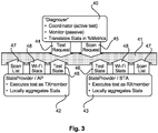
- the test application is illustrated in figure 3 as a "Diagnozer” 40, which is a coordinator for an active test and a monitor for a passive test, and converts received data in percentages and link speeds and presents the results to a user.
- the test application 40 is connected via a data bus 41 with a statistics provider application 42 included in the access point 1 and a statistics provider 43 included in the station 2.
- the data bus 41 uses for example a publish/subscribe messaging system for an exchange of control commands and data with the statistics providers 42 and 43, which is independent of the operating system of the station 2.
- the test application 40 requests a test request 44 or a scan request 45, which are submitted via the data bus 41 to the statistics providers 42, 43.
- the test request 44 can be a passive monitoring test or an active test.
- Via the scan request 45 lists with recognized neighboring WLAN nodes are requested from the access point 1 and/or station 2.
- the statistics providers 42, 43 receive the test state information 46 of the test request 44 and provide, when required, scan list 47, which includes all neighboring WLAN nodes being recognized when the access point 1 and/or station 2 scan the WLAN channels, and "Wi-Fi Stats", measured data rates 48, being obtained by the tests.
- the data transmitted from the transmit member, access point 1 include in particular measured data rates: MaxPhyRate 31, PhysLimitsPhyRate 31, TrainedPhyRate 32, MediumBusy, MediumBusyOtherWi-Fi 33, %PS 35, ThroughputPSon 36, etc.
- the data transmitted by the statistics provider 43, the receive member include in particular RSSI and the scan list.
- the test request 44 is published via the data bus 41 by the test application 40 and includes a test identification number (TestRequest.id), MAC addresses of receive member and transmit member, (sourceMAC, destinationMAC), test type: ping or layer 2 test, configuration, etc.
- the test can be a normal test, in which the receive member is a statistics provider and publishes for example station statistics to the test application 40.
- the test can be also a blind test, in which the receive member is an associated station not providing any statistics, and the transmit member executes a test autonomously. In this case, the test application 40 can use information only from the access point 1, the transmit member.
- the scan request 45 is an event and published by the test application 40.
- the scan list 47 is a state and is published by everyone having subscribed to the scan request 45.
- test measurements are synchronized between the access point 1 and the station 2.
- synchronization is not required.
- the statistics providers 42, 43 publish locally aggregated statistics via the data bus 41, for example every 30 sec in case of passive monitoring, except when interrupted by an active test.
- the station 2 samples RSSI and receive data rates every second and calculates a filtered RSSI average over the tests duration, for example 30 sec.
- the filtering includes for example a threshold of 1 kbps, and RSSI samples are dropped if the receive data rate is below the threshold.
- the RSSI samples are aggregated, when the receive data rate is above that threshold.
- the rate adaptation algorithm in any WLAN node aims at reducing packet loss by stepping down to lower modulation rates and less spatial streams. If we define "TrainedPhyRate" 32 as the modulation rate that is used when the link is trained, we can approximatively assume that problems on receive side/packet loss is minimal at this physical layer rate.
- Further performance loss can be caused by the CCA mechanism blocking the transmitter to send packets. This can be assessed by using the CCA statistics: medium busy/medium busy other Wi-Fi 33. Actual available performance can be assessed through CCA statistics and knowledge of TrainedPhyRate 32, or through an active test. This is known to those skilled in the art.
- WLAN is using a shared medium concept based on a CSMA-CA (Carrier Sense Multiple Access / Collision Avoidance) medium access method. Performance will drop if more devices are sharing the medium. More difficult is to distinguish what is causing the problems on receiver side, i.e. interference > please change channel; or physics > please move AP or STA.
- CSMA-CA Carrier Sense Multiple Access / Collision Avoidance
- connection speed drops due to the presence of interference. Instead of SNR (signal to noise ratio), SiNR (signal to interference noise ratio) applies which impacts either the physical layer rate or the medium availability.
- SiNR signal to interference noise ratio
- Physics The connection speed drops due to SNR degradation and a reduced ability to use multiple spatial streams (MIMO: multiple-input and multiple-output). It is noted that MIMO systems leverage on the ability to use a multitude of spatial streams in order to achieve high link speeds.
- the PhysLimitsPhyRate 31, figure 2 can be understood as the boundary between performance lost due to physical effects ("physics") and performance lost due to interference at the receiver side.
- PhysLimitsPhyRate 31 is partly defined by extrapolating what physical layer rate would be used in case of the measured signal strength (RSSI) - in the absence of interference. This extrapolation may be based for example on reference measurements in a clean environment - this can be in a conducted set up or in a radiated set up. This covers performance lost due to high path loss, leading to a low signal strength.
- RSSI measured signal strength
- Figure 4 shows a diagram depicting the performance in percent, related to the PhysLimitsPhyRate 31, as a function of RSSI in dBm.
- the data rate is essentially unaffected above an RSSI of 70 dBm, but drops rapidly below 70 dBm and reaches zero below 90 dBm.
- the measured performance, measured layer 2 throughput in percent x correction factor 1.16 is conform with the theoretical performance: PhysLimitsPhyRate 31 in percent based on RSSI and number of observed spatial streams, with the exception of a region below -85 dBm, where there is some deviation.
- MaxPhyRate 30 The maximum available physical layer rate for the transmission between the access point 1 and the station 2, MaxPhyRate 30, as negotiated, can be obtained for example from the figure 5 showing a table, which includes the maximum available data rates for the IEEE standards 802.11b, 802.11g and 802.11n as a function of the number of spatial streams (MIMO Configuration), channel bandwidth (20 or 40 MHz), and SGI (Short Guard Interval) enabled or not enabled.
- MIMO Configuration the number of spatial streams
- channel bandwidth 20 or 40 MHz
- SGI Short Guard Interval
- the performance obtained with regard to figure 4 has been transformed for the example: IEEE 802.11n with 20 MHz channel bandwidth and two spatial streams and depicted in figure 6 .
- the link layer data rate IN in Mb/s is drawn as a function of the RSSI in dBm.
- OSI Layer 2 rate a factor of 1,16 has to be taken into account with regard to the maximum obtainable physical layer rate of 130 Mb/s.
- the curve relates to a packet loss of ⁇ 1%.
- RSSI Received Signal Strength
- Physical Rate Average averaging of the parameters: Modulation rate (PhyRate) and/or the number of Spatial Streams.
- the second factor defining PhysLimitsPhyRate 31 is related to the possibility to set up multiple spatial streams or not. Depending on the environment, presence or absence of multiple reflections/spatial paths, (de-) correlation of the signal seen by the different receivers. To take this into account, the measured average number of spatial streams is used, as used by the link under traffic.
- the method can be used therefore as a passive monitoring application monitoring the Wi-Fi performance and informing a user when any of the described problems occur on its Wi-Fi link.
- the method also called here Wi-FiTM Doctor, consists advantageously of two parts: an application running on client devices (Android, iOS, PC, etc%) and an application running on the gateway (AP).
- AP application running on the gateway
- 802.11n introduces MIMO, multiple Spatial Streams:
- the active test includes in particular the following steps:
- APStats MACAddress BSSID .
- AssociatedStationStats MACAddress MAC Android Rxmember .
- trainedPhyRateTX PhysLimitsPhyRate 31 look-up of ReferencePhyRate RSSI ⁇ TXRXcorFac Look-up table (RSSI > ReferencePhyRate) provided in figures 4 , 6
- STAStats[MACAddress MAC Android Rxmember].
- APStats[MACAddress BSSID].
- AssociatedStationStats[MACAddress MAC Android Rxmember].
- RSSI TXRXcorFac max PINGspatsUL / PINGspatsDL , 1
- a Wi-Fi node For calculating losses of a wireless link of a Wi-Fi node between a customer premises equipment device and a station in a correct manner, it is in particular important to take samples of one or several of the following parameters in a defined time interval, e.g. every second: Received Signal Strength (RSSI), Modulation rate (Physical Rate) and/or the number of spatial streams used for a given Wi-Fi link, and calculating an average for that parameters by including a filtering of said parameters.
- the filtering is used in particular to filter out non-data frames, e.g. control frames, which do not contribute to the Wi-Fi transmission rate.
- the obtained results can be displayed for a user on a display of his station 2 by the test application 40 for example as consecutive blocks forming a semi-circle, as shown in figure 7 .
- the data rates as explained with regard to figure 2 define the length of each block.
- a pointer P visualizes the finally attainable data rate 36, which is in this embodiment 23% of the theoretically available data rate of 130 MB/s.
- Each of the blocks include a question mark Q, which can be selected by the user for example by using a mouse or a touchpad; and by selecting a question mark Q, the user is informed about the problem which causes the throughput loss leading to the contribution of this block and gives an advice for the user, how he can improve the situation.
- the question mark Q of the block 50 the user is informed that the obtained data rate during the test was only 28 MB/s, 23% of the theoretically maximum rate of 130 MB/s.
Landscapes
- Engineering & Computer Science (AREA)
- Computer Networks & Wireless Communication (AREA)
- Signal Processing (AREA)
- Environmental & Geological Engineering (AREA)
- Data Mining & Analysis (AREA)
- Physics & Mathematics (AREA)
- General Physics & Mathematics (AREA)
- Mathematical Analysis (AREA)
- Mathematical Optimization (AREA)
- Mathematical Physics (AREA)
- Probability & Statistics with Applications (AREA)
- Pure & Applied Mathematics (AREA)
- Algebra (AREA)
- Mobile Radio Communication Systems (AREA)
- Monitoring And Testing Of Transmission In General (AREA)
- Telephone Function (AREA)
Description
- The invention relates to the field of wireless nodes and respective devices communicating with each other via a wireless communication.
- Access gateways are widely used to connect devices a the home to the Internet or any other wide area network (WAN). Access gateways use in particular digital subscriber line (DSL) technology that enables a high data rate transmission over copper lines or optical lines. Residential gateways, but also other devices such as routers, switches, telephones and set-top boxes, are understood in this context as customer premises equipment (CPE) devices.
- Access gateways including wireless technology have a key role in today's home and professional environments. A mechanism for connecting wireless devices to a local area network (LAN) is called Wi-Fi, which is a brand name of the Wi-Fi Alliance for devices using the IEEE 802.11 family of standards for wireless data transmission. The IEEE 802.11 standards define two types of wireless nodes, a general wireless device that can connect to other devices called a station (denoted as STA) and a special type of a STA that is in control of the network, namely an access point (denoted AP). A Wi-Fi network, often called a WLAN (wireless local area network), consists of an AP with one or several STA connected to the AP.
- Due to its flexible and "invisible" nature, a lot of LAN applications are utilizing Wi-Fi rather than the classical wired Ethernet approach. This widespread usage of wireless LAN has exposed however a serious downside of using a shared medium technology: interference. Interference, both Wi-Fi and non-Wi-Fi related, leads to a degraded user experience due to the nature of IEEE 802.11. In its most common form, IEEE 802.11 networks apply a medium access method in which collisions are avoided by sensing that the medium is used (denoted as CSMA-CA). The medium access method is also commonly known as "listen before talk", describing the essence of the method. Interference from any nature can hence block the medium and force all nodes to remain silent.
- A further technique that may be used to avoid interference is referred to as "Clear Channel Assessment" (CCA). Clear channel assessment determines whether a wireless communication channel is "occupied", e.g., "busy" with another wireless communication and/or has an amount of interference that makes the wireless communication channel unsuitable for communication. In this way, it is determined whether the wireless communication channel is available or not available for communication, e.g. occupied or not occupied.
- Another impact of interference can be packet loss at the receiver side, leading to a reduction of the physical data rate. In this case, the interference is not detected by the CCA of the transmitter, but is decreasing the SINR (Signal to Noise and Interference Ratio) of the Wi-Fi packets as seen by the receiver.
- Therefore, in certain circumstances, the Wi-Fi connection can suffer from poor performance and even connection loss. Some of these circumstances are obvious and easy to explain to an end user. For example, if the distance between the station and the access point is too large, then signal levels are low and performance will degrade. Other circumstances are "invisible" and not understood by the end user, e.g. a hidden node. A hidden node is invisible to some of the nodes of a network, leading to a practical failure of the CSMA-CA method, which can cause packet collision/corruption over air. In many cases, the end user is not able to diagnose the problem source and correct the issue.
- In-home Wi-Fi network connectivity is correspondingly one of the main Internet service provider support costs and causes for help-desk calls. Today's focus for operators is mainly on Wi-Fi network installation, associating a station with an access point. Internet service providers are therefore searching for ways to get a better understanding of the end user's wireless environment including link quality and performance.
- Related to Wi-Fi performance, operators can use a remote management protocol such as Broadband Forum (noted BBF) TR-069 protocol, which provides access to Wi-Fi parameters as defined in the Internet Gateway Device data model BBF TR-181. But the information available via TR-069 is very limited and focused on data traffic. In some cases, an end user is faced with an issue preventing Wi-Fi connection at all, correspondingly rendering TR-069 monitoring useless. Hence, when an end user calls a help-desk, it can be a lengthy and expensive process to describe the home topology and diagnose the issue at hand.
- The ideal way to analyze Wi-Fi issues, e.g. connection setup, interference, throughput, ..., is by looking into the master node of the wireless LAN, namely the AP. The AP, as defined in IEEE 802.11, controls the network, hence all data and network control must be visible by the AP. The AP today can deliver statistics regarding packet transmission and signal levels, but only if a link between the AP and a STA can be established. The real issue why a link is dropped or why throughput is low, remains hidden to the internals of the AP. Full packet inspection is not possible, hence leaving technology or protocol analyzers in the dark when it comes down to pinpointing the real issues in a wireless LAN. Today, at best an AP can deliver statistics but no view on what is actually happening in the wireless network.
- Wi-Fi performance can be degraded because of the following categories. For each category, a different action has to be taken to improve things:
- Power Save settings of the Station
>> Change power save setting of the station - Sharing the medium (properly) with other Wi-Fi devices
>> Use another channel that is less occupied (or prioritize Wi-Fi traffic properly using e.g. Wi-Fi Multimedia priorities (WMM, IEEE 802.11e) - Interference at Transmitter side
>> Change to channel without interference (or remove interference source) - Interference at Receiver side
>> Change to channel without interference (or remove interference source) - Physics: high path loss, impossibility to set up multiple spatial streams
>> move AP or Station -
EP0713632 relates to low-power wireless systems and more particularly to pico-cellular wireless systems which use of co-located zones to permit mobility traffic. -
US2012/0287797 describes a method performed by a receiver wireless station for beamforming in a wireless local area network. -
US2013/0039212 describes a method for controlling transmission power of a wireless device in a Wi-Fi network. -
US2008/0192724 describes a method for adjusting transmission rates of wireless devices in an ad-hoc network. - The problem to solve is to have an application that can correctly analyze Wi-Fi performance issues and indicate the correct category causing the issue, so that the end user can be guided to a suitable corrective action.
- The invention is as set out in the
independent claims - Preferred embodiments are defined in the dependent claims.
- The methods described rely on the availability of correct statistics related to the quality of the Wi-Fi link, such as but not limited to Signal Strength (RSSI) as well as of the Modulation rate (Physical Rate) and the number of Spatial Streams used for a given Wi-Fi link. It is not a trivial task to obtain the correct statistics, as there are power save mechanisms in place that influence the above mentioned parameters in such a way that they cannot be used as such to understand the quality of the Wi-Fi link. E.g. a Wi-Fi implementation can reduce the number of spatial streams and/or the modulation rate to reduce power consumption - rather than in reaction to interference which would prohibit the use of multiple spatial streams and/or of higher modulation rates.
- When doing an active test - i.e. forcing traffic through the Wi-Fi link, most implementations will abandon these power-save actions, and a normal averaging of the above- mentioned parameters will provide - in most cases - accurate statistics that yield a correct quality assessment of the Wi-Fi link. In case of Wi-Fi quality monitoring, however, such an active test is to be avoided. So for such passively monitoring tools, a way was found to collect adequate statistics that can avoid power save artefacts.
- The monitoring method takes samples of the above-mentioned parameters on a short time scale, e.g. every second. Rather than taking just the average of the samples taken over a certain interval, (averaging is certainly needed to obtain reliable results), a "filtered average" is used. This means that only those samples are retained for calculating the average that are taken at moment when sufficient traffic is flowing over the link. This can be deduced from the TxRate and RxRate parameters that are also sampled every second. By taking the correct threshold of TxRate and/or RxRate, the "filtered average" can avoid the artefacts caused by power save mechanisms, and ensure that only correctly "trained" values of the relevant parameters such as PhyRate, RSSI, and number of spatial streams are considered.
- Preferred embodiments of the invention are explained in more detail below by way of example with reference to schematic drawings, which show:
- Fig. 1
- an access point communicating with a station via a wireless communication,
- Fig. 2
- data rates of a wireless communication according to
figure 1 , - Fig. 3
- a test application including a coordinator for an active test and a monitor for a passive test,
- Fig. 4
- a performance data rate as a function of RSSI in dBm,
- Fig. 5
- a table showing maximum available data rates for IEEE standards 802.11b, 802.11g and 802.11n,
- Fig. 6
- data rates being obtained by applying
figure 4 to a wireless transmission according to IEEE 802.11n with a 20 MHz channel bandwidth and two spatial streams, and - Fig. 7
- test results being displayed on a display as consecutive blocks forming a semi-circle.
- In the following description, example methods for monitoring or analyzing a wireless (Wi-Fi) link of a wireless node of an access point, e.g. a customer-premises equipment device, or a station are described, as well as respective circuits performing the methods. For purposes of explanation, various specific details are set forth in order to provide a thorough understanding of preferred embodiments. It will be evident, however, to one skilled in the art that the present invention may be practiced without these specific details.
- A customer premises equipment (CPE) device includes for example a controller, e.g. a microprocessor, a non-volatile memory, in which an operating system is stored, a volatile memory for the operation of the CPE device, a wireless node for a wireless operation, and a broadband connection, e.g. an xDSL connection. The wireless node includes a complex software driver, a physical layer with data buffers, and an antenna. A CPE device of this kind is for example an access gateway, e.g. a residential gateway, which has a central position within a wireless local area network (WLAN).
- The wireless node is controlled by the software driver which executes a lot of background tasks during operation of the wireless node, e.g. dynamic rate adaptation, packet aggregation, channel quality monitoring, to name some. On top of signal manipulations, the wireless driver also embeds the IEEE 802.11 protocol stack with the associated IEEE defined management and control messaging. The wireless driver will hence inject a lot of management and control packets in the data stream, making it impossible to analyze a link by transparently looking at the data frame exchange only.
- A use case is schematically depicted in
figure 1 : Anaccess point 1 communicates with astation 2 via awireless communication 3. Theaccess point 1 includes a circuit comprising amicroprocessor 10, a volatile and anon-volatile memory 11, awireless node 12 for the wireless communication, and atest application 13. Thestation 2 includes a second circuit comprising amicroprocessor 20, a volatile and anon-volatile memory 21, awireless node 22 for the wireless communication, and atest application 23. Thewireless node 12 includes aphysical layer 14 and alink layer 15, and the Wi-Fi node 22 includes aphysical layer 24 and alink layer 25. - The
test application 13 comprises instructions for themicroprocessor 10 and thetest application 23 comprises instructions for themicroprocessor 20, which are included for diagnosing thewireless communication 3 and which gather an information set about thewireless communication 3. The information set includes in particular achievable data rate, physical layer data rate, multiple spacial streams, channel bandwidth, medium availability and Received Signal Strength Indicator (RSSI). Test data can be gathered in a passive mode, in which a data transmission is monitored between theaccess point 1 and thestation 2 or vice versa, or in an active mode, in which a data transmission is forced between theaccess point 1 and thestation 2. -
Figure 2 illustrates the possibilities which have to be considered when diagnosing the Wi-Fi performance between theaccess point 1 and thestation 2. An unidirectional link 3' from theaccess point 1 to thestation 2 is examined. The theoreticalmaximum data rate 30 for this link is given by the capabilities of theaccess point 1 and thestation 2, called here MaxNegotiatedPhyRate or MaxPhyRate, which is for example 130 MB/s in case an IEEE 802.11n standard with 20 MHz channel bandwidth and two spatial streams is selected for the transmission between theaccess point 1 and thestation 2. This is thus the maximum achievable link speed, 100%, which is only a theoretical value, because for most situations physical limitations come into play: the received signal strength RSSI at the station side is reduced for example due to the distance between theaccess point 1 and thestation 2 and path loss due to any walls or other obstacles and reflections. Also the number of spatial streams has to be determined. The practicallyattainable data rate 31, called here PhysLimitsPhyRate, is therefore less than thedata rate 30. - Further performance can be lost due to interference close to the
station 2, which is not seen by theaccess point 1, called here far end interference FEIF: this can be any microwave source like RF Babyphone, microwave oven or a hidden Wi-Fi node, and leads to a further reduced data rate, called here TrainedPhyRate 32. Similar interference can appear at theaccess point 1, called here near end interference FEIF: This will reduce theavailable data rate 32 to adata rate 33, MediumBusyOtherWiFi. Further performance can be lost by sharing the medium with other Wi-Fi traffic, which can be caused by WLAN traffic in the home network, but also by Wi-Fi traffic of a neighboring network. This reduceddata rate 34 is called here AvailableThroughputPSoff. Another reduction of the data rate can be caused by performance lost due to a power save mode, for example implemented in a mobile device, e.g. a smartphone. Some percentage of its time, thestation 2 may be in a sleeping mode, called her%PS 35. Thefinal data rate 36, what a user can get as the real data rate from theaccess point 1 to thestation 2 is calledThroughputPSon 36. - In order to monitor the data traffic of the physical layer, the
layer 1 of the OSI (Open Systems Interconnection Model) model, the traffic that is transmitted and received by the Wi-Fi node of the residential gateway, the residential gateway includes a test application receiving all received and transmitted packets. The test application has access to the following blocks: - Transmit (TX) packet queue, TX packets
- Receive (RX) packet queue, RX packets
- Transmit / Receive signal indicators (RSSI)
- The test application is illustrated in
figure 3 as a "Diagnozer" 40, which is a coordinator for an active test and a monitor for a passive test, and converts received data in percentages and link speeds and presents the results to a user. Thetest application 40 is connected via adata bus 41 with astatistics provider application 42 included in theaccess point 1 and astatistics provider 43 included in thestation 2. Thedata bus 41 uses for example a publish/subscribe messaging system for an exchange of control commands and data with thestatistics providers station 2. - The
test application 40 requests atest request 44 or ascan request 45, which are submitted via thedata bus 41 to thestatistics providers test request 44 can be a passive monitoring test or an active test. Via thescan request 45, lists with recognized neighboring WLAN nodes are requested from theaccess point 1 and/orstation 2. Thestatistics providers test state information 46 of thetest request 44 and provide, when required, scanlist 47, which includes all neighboring WLAN nodes being recognized when theaccess point 1 and/orstation 2 scan the WLAN channels, and "Wi-Fi Stats", measureddata rates 48, being obtained by the tests. - The data transmitted from the transmit member,
access point 1, include in particular measured data rates:MaxPhyRate 31,PhysLimitsPhyRate 31,TrainedPhyRate 32, MediumBusy, MediumBusyOtherWi-Fi 33,%PS 35,ThroughputPSon 36, etc. The data transmitted by thestatistics provider 43, the receive member, include in particular RSSI and the scan list. - The
test request 44 is published via thedata bus 41 by thetest application 40 and includes a test identification number (TestRequest.id), MAC addresses of receive member and transmit member, (sourceMAC, destinationMAC), test type: ping orlayer 2 test, configuration, etc. The test can be a normal test, in which the receive member is a statistics provider and publishes for example station statistics to thetest application 40. The test can be also a blind test, in which the receive member is an associated station not providing any statistics, and the transmit member executes a test autonomously. In this case, thetest application 40 can use information only from theaccess point 1, the transmit member. Thescan request 45 is an event and published by thetest application 40. Thescan list 47 is a state and is published by everyone having subscribed to thescan request 45. - For the statistics being provided by an active test, the test measurements are synchronized between the
access point 1 and thestation 2. For a passive monitoring, synchronization is not required. - The
statistics providers data bus 41, for example every 30 sec in case of passive monitoring, except when interrupted by an active test. In case of passive monitoring, thestation 2 samples RSSI and receive data rates every second and calculates a filtered RSSI average over the tests duration, for example 30 sec. The filtering includes for example a threshold of 1 kbps, and RSSI samples are dropped if the receive data rate is below the threshold. The RSSI samples are aggregated, when the receive data rate is above that threshold. - For the passive monitoring, it is further important to separate issues at the receiver side from CCA (Clear Channel Assessment) related issues. There the fact can be used that the rate adaptation algorithm in any WLAN node aims at reducing packet loss by stepping down to lower modulation rates and less spatial streams. If we define "TrainedPhyRate" 32 as the modulation rate that is used when the link is trained, we can approximatively assume that problems on receive side/packet loss is minimal at this physical layer rate.
- Further performance loss can be caused by the CCA mechanism blocking the transmitter to send packets. This can be assessed by using the CCA statistics: medium busy/medium busy other Wi-
Fi 33. Actual available performance can be assessed through CCA statistics and knowledge ofTrainedPhyRate 32, or through an active test. This is known to those skilled in the art. - Medium sharing: WLAN is using a shared medium concept based on a CSMA-CA (Carrier Sense Multiple Access / Collision Avoidance) medium access method. Performance will drop if more devices are sharing the medium. More difficult is to distinguish what is causing the problems on receiver side, i.e. interference > please change channel; or physics > please move AP or STA.
- Interference: The connection speed drops due to the presence of interference. Instead of SNR (signal to noise ratio), SiNR (signal to interference noise ratio) applies which impacts either the physical layer rate or the medium availability. Physics: The connection speed drops due to SNR degradation and a reduced ability to use multiple spatial streams (MIMO: multiple-input and multiple-output). It is noted that MIMO systems leverage on the ability to use a multitude of spatial streams in order to achieve high link speeds.
- The
PhysLimitsPhyRate 31,figure 2 , can be understood as the boundary between performance lost due to physical effects ("physics") and performance lost due to interference at the receiver side.PhysLimitsPhyRate 31 is partly defined by extrapolating what physical layer rate would be used in case of the measured signal strength (RSSI) - in the absence of interference. This extrapolation may be based for example on reference measurements in a clean environment - this can be in a conducted set up or in a radiated set up. This covers performance lost due to high path loss, leading to a low signal strength. -
Figure 4 shows a diagram depicting the performance in percent, related to thePhysLimitsPhyRate 31, as a function of RSSI in dBm. As can be seen, the data rate is essentially unaffected above an RSSI of 70 dBm, but drops rapidly below 70 dBm and reaches zero below 90 dBm. The measured performance, measuredlayer 2 throughput in percent x correction factor 1.16, is conform with the theoretical performance:PhysLimitsPhyRate 31 in percent based on RSSI and number of observed spatial streams, with the exception of a region below -85 dBm, where there is some deviation. - The maximum available physical layer rate for the transmission between the
access point 1 and thestation 2,MaxPhyRate 30, as negotiated, can be obtained for example from thefigure 5 showing a table, which includes the maximum available data rates for the IEEE standards 802.11b, 802.11g and 802.11n as a function of the number of spatial streams (MIMO Configuration), channel bandwidth (20 or 40 MHz), and SGI (Short Guard Interval) enabled or not enabled. - The performance obtained with regard to
figure 4 has been transformed for the example: IEEE 802.11n with 20 MHz channel bandwidth and two spatial streams and depicted infigure 6 . The link layer data rate IN in Mb/s is drawn as a function of the RSSI in dBm. For the link layer (OSI Layer 2) rate, a factor of 1,16 has to be taken into account with regard to the maximum obtainable physical layer rate of 130 Mb/s. The curve relates to a packet loss of <1%. - Alternatively, an average of the parameters: Received Signal Strength (RSSI), Modulation rate (PhyRate) and/or the number of Spatial Streams is used, by measuring the parameters under traffic by including a filtering of the parameters, as described below, to calculate the
PhysLimitsPhyRate 31. - The second
factor defining PhysLimitsPhyRate 31 is related to the possibility to set up multiple spatial streams or not. Depending on the environment, presence or absence of multiple reflections/spatial paths, (de-) correlation of the signal seen by the different receivers. To take this into account, the measured average number of spatial streams is used, as used by the link under traffic. - The following use case variations are possible: Single AP and multiple STAs running the monitoring method:
- The test application runs on multiple devices, e.g. Android devices and on the AP, diagnosing any AP - STA link whereby the diagnosis is performed on any Android device running the test application. As such one can run a test from an Android device running the application. Also. as such one can run a test from anywhere in the home - provided the application has network connectivity - decoupled from the actual devices under test.
- The test application runs on a single e.g. Android device and on the AP and diagnoses any AP - STA link. The fact that a
layer 2 test is used and that the AP is gathering 90% of the statistics allows analysis of any WLAN device even if it is not running the test application. The application will know that it is diagnosing a device not running the test application and will compensate for it. - The method can be used therefore as a passive monitoring application monitoring the Wi-Fi performance and informing a user when any of the described problems occur on its Wi-Fi link.
- The method, also called here Wi-Fi™ Doctor, consists advantageously of two parts: an application running on client devices (Android, iOS, PC, etc...) and an application running on the gateway (AP). When using both, optimum measurement results are obtained at both ends of the wireless link by reading critical values from the wireless drivers. In particular the following data are considered by the method:
- ▪ Physics 1: High Path Loss
- ▪ Distance/walls between Gateway and Station
- ▪ Bathroom/kitchen/metal cupboards (or other metal/water) obstructing radio path
- ▪ Invisible construction "details" like metal screed reinforcement mesh, "chicken wire" walls in Victorian houses, reflective window coating,..
- ▪ Physics 2: 11n-only: MIMO multiple spatial streams not OK
▪ Too difficult to explain to end user. - ▪ NON-WLAN interference: - at Transmit-side or at Receiver-side
- ▪ Babyphones, analogue TV senders, BlueTooth devices, Microwave Ovens,...
- ▪ But also: WLAN not recognised as WLAN: (spatially) hidden nodes, WLAN nodes in adjacent overlapping channels
- ▪ 802.11 MAC (Medium-Access-Layer) incapable of handling efficiently > collapse
- ▪ Congestion: WLAN traffic from neighbouring WLANs
▪ Bandwidth decreased by sharing the same medium (802.11 MAC in action)
▪ Slow Stations (11b or just a STA far away from AP) dictate the total bandwidth! - ▪ Rate Adaption, see
Fig. 6 ,
at the heart of Wi-Fi- ▪ If Signal gets weaker
- > SINR decreases
- > Packet Loss
- > step back to slower physical rates (PhyRates)
- ▪ Same happens with increasing
Noise or Interference at RX-side - ▪ Rate Adaptation algorithm strives for ∼zero packet loss
- ▪ If Signal gets weaker
- ▪ Symptom RSSI
▪ Indicator for Signal Strength - ▪
Symptom TrainedPhyRate 32- ▪ = PhyRate when traffic flowing
- ▪ Indicator for Signal/Interference&Noise Ratio
- ▪ Requires fast (∼second) correlation between PhyRate and Rate
- 802.11n introduces MIMO, multiple Spatial Streams:
- System tries to set up multiple spatial streams: - different data streams on transmitting antennas
- Orthogonal to Rate Adaptation
> separate Symptom: number of spatial streams - Performance "Loss" by failure to use multiple spatial streams:
- Big impact:
E.g. 2x2: 50% - Known to be caused by
physical effects (Physics)
e.g. if no reflections - Shown to be caused by
Interference at RX side - Clear Channel Assessment, CCA
at the heart of Wi-Fi's CSMA-CA, also known as "Listen before Talk" - Wi-Fi Transceiver is continuously assessing whether the channel is free.
- Symptom: MediumBusy (in percent of time)
- Different CCA thresholds
- For Wi-Fi frames: very low threshold
Efficient "Wait2":
frame duration known
> Symptom:MediumBusyOtherWiFi 33 - For Interference: higher threshold
Less efficient: duration not known - The active test includes in particular the following steps:
- ▪ Step 1: Launches Ping Test from AP to STA, e.g. an Android device
- ▪ Goal1: wake up TX and RX members before TX test
- ▪ Goal2: solve #spatial streams dilemma by checking RX and TX physical rate (PhyRate) at the AP
- ▪ Publish TestRequest 44:
- ▪ TestRequest.id = random number, e.g. "PingTestId"
- ▪ sourceMAC = MAC address AP
- ▪ destinationMAC = MAC address STA RXmember
- ▪ type = 0 (ping test)
- ▪ Duration = 5s
- ▪ Packet Size = 100 byte
- ▪ WMM Class = 1 (best effort)
- ▪ When test done: retrieve radioStats[testId=PingTestId], remove TestRequest
- ▪ Step2: Launches Active layer 2 (L2) TX test from AP to Android STA
- ▪ Publish TestRequest 44:
- ▪ TestRequest.id = random number, e.g. "TXtestId"
- ▪ sourceMAC = MAC address AP
- ▪ destinationMAC = MAC address targeted STA (Android) RX member
- ▪ Type = 1 (TX test)
- ▪ Duration = 10s
- ▪ Packet Size = 1500 byte
- ▪ WMM Class = 1 (best effort)
- ▪ When test done: retrieve radioStats[testId=TXtestId], remove TestRequest
- ▪ Publish TestRequest 44:
- Step3: Display categories in percent on graphical user interface (GUI), see also
figure 7 :

-
MaxPhyRate 30 in data model (QDM):
- TrainedPhyRate in QDM:


figures 4 ,6 - RSSI in QDM: RadioStats[testId=TXtestId AND radio=radioID of Android RXmember]. STAStats[MACAddress=MAC Android Rxmember].RSSI Blind test: use RadioStats[testId=TXtestId AND radio=radioID of AP]. APStats[MACAddress=BSSID]. AssociatedStationStats[MACAddress = MAC Android Rxmember].RSSI

- ▪ %Physics (continued)
- ▪ PINGspatsUL in QDM: RadioStats[testId=PingtestId AND radio=radioID of AP]. APStats[MACAddress = BSSID].AssociatedStationStats. [MAC Address = MAC Android Rxmember]. avgSpatialStreamsRX
- ▪ PINGspatsDL in QDM: RadioStats[testId=PingtestId AND radio=radioID of AP]. APStats[MACAddress = BSSID].AssociatedStationStats. [MAC Address = MAC Android Rxmember]. avgSpatialStreamsTX
- ▪ Look Up of ReferencePhyRate(RSSI) units kbps, e.g. from reference measurements,
figures 4 ,6 - ▪ For 11n 2x2: MIN (MAX ( (RSSI+82)*100000/37 , 0), 100000)
i.e. linear between (RSSI=-82dBm, 0kbps) and (RSSI=-45dBm, 100000kbps),
0kbps when RSSI<-82dBm, 100000kbps when RSSI>-45dBm - ▪ For 11n 1x1: MIN (MAX ( (RSSI+82)*60000/23 , 0),60000) i.e. linear between (RSSI=-82dBm, 0kbps) and (RSSI=-59dBm, 60000kbps),
0kbps when RSSI<-82dBm, 60000kbps when RSSI>-59dBm
- ▪ For 11n 2x2: MIN (MAX ( (RSSI+82)*100000/37 , 0), 100000)
- ▪

- ▪

- ▪ CorFac = correction factor to translate L2 DataRate to PhyRate >> experimentally:
- ▪ for 11g CorFac = 2
- ▪ for 11n (with AMPDU) CorFac is 1,43
- ▪ ThroughputPSon in QDM: RadioStats[testId=TXtestId AND radio=radioID of AP].APStats[MACAddress = BSSID].AssociatedStationStats[MACAdd ress = MAC Android Rxmember].dataRateTX
- ▪ CorFac = correction factor to translate L2 DataRate to PhyRate >> experimentally:
- ▪

- ▪ MediumBusyOtherWiFi in QDM = sum of RadioStats[testId=TXtestId AND radio=radioID of AP].APStats[MACAddress = BSSID].RXTimeFractionOBSS and RadioStats[testId=TXtestId AND radio=radioID of AP].APStats[MACAddress = BSSID].RXTimeFractionIBSS and RadioStats[testId=TXtestId AND radio=radioID of AP].APStats[MACAddress = BSSID].TXTimeFraction
- ▪ take into account traffic sent by AP in parallel to Txtest (e.g. to other stations)
- ▪ Note: ceiling: 100%-%Physics - %FEIF - %What you get!
- ▪

- ▪ MediumAvailable in QDM: RadioStats[testId=TXtestId AND radio=radioID of AP].mediumAvailable
- ▪ Note: needed as some power save mechanisms (PS-poll) are not reflected correctly in the parameter "powerSaveTimeFraction" (as the AP is not aware of the exact timings).
- ▪ Note: ceiling: 100%-%Physics - %FEIF - %What you get! - %SharingWiFi
- ▪ %NEIF = 100% - %Physics - %FEIF - %WhatYouGet! - %Sleeping - %SharingWiFi ▪
Note: ceiling: 0% (i.e. cannot be negative). - ▪ Proposed on GUI in case %FEIF is dominant in test result
- ▪ Publish ScanRequest to AP and STA under test
▪ Radio = Radio id of AP and STA - ▪ When the two ScanList are ready: retrieve all ScanListEntry
▪ ScanListEntries with a channel equal to Radio[id of TXMember].channel- ▪ If present on the AP's ScanList as wells as on the STA's ScanList >> mark as "Sharing Channel"
- ▪ If present on the AP's ScanList and not on the STA's ScanList >> mark as "Hidden for STA"
- ▪ If present on the STA's ScanList and not on the AP's ScanList >> mark as "Hidden for AP"
- ▪ ScanListEntries with a channel equal to Radio[id of TXMember].channel -3, -2, -1, +1, +2, or +3 >> mark as "Overlapping"
- ▪ Publish ScanRequest to AP and STA under test
- ▪ Display only the marked ScanListEntries
- For calculating losses of a wireless link of a Wi-Fi node between a customer premises equipment device and a station in a correct manner, it is in particular important to take samples of one or several of the following parameters in a defined time interval, e.g. every second: Received Signal Strength (RSSI), Modulation rate (Physical Rate) and/or the number of spatial streams used for a given Wi-Fi link, and calculating an average for that parameters by including a filtering of said parameters. The filtering is used in particular to filter out non-data frames, e.g. control frames, which do not contribute to the Wi-Fi transmission rate.
- The obtained results can be displayed for a user on a display of his
station 2 by thetest application 40 for example as consecutive blocks forming a semi-circle, as shown infigure 7 . The data rates as explained with regard tofigure 2 define the length of each block. A pointer P visualizes the finallyattainable data rate 36, which is in thisembodiment 23% of the theoretically available data rate of 130 MB/s. Each of the blocks include a question mark Q, which can be selected by the user for example by using a mouse or a touchpad; and by selecting a question mark Q, the user is informed about the problem which causes the throughput loss leading to the contribution of this block and gives an advice for the user, how he can improve the situation. In case of the question mark Q of theblock 50, the user is informed that the obtained data rate during the test was only 28 MB/s, 23% of the theoretically maximum rate of 130 MB/s. - Also other embodiments of the invention may be utilized by one skilled in the art without departing from the scope of the present invention. The method as described may be used in particular for all kinds of access points and stations using a wireless transmission, e.g. Wi-Fi. The invention resides therefore in the claims herein after appended.
Claims (13)
- A method for monitoring a wireless link (3) of a wireless node of a customer premises equipment, CPE, device (1) during operation of the CPE device for analyzing the performance of the wireless link, the method being performed by the CPE and comprising:taking samples of a transmission rate, TxRate, and a receive rate, RxRate, representative of a data traffic flowing over the wireless link in a defined time interval,taking samples of at least one of the following parameters in said time interval: Received Signal Strength, RSSI, modulation rate, and number of spatial streams used for the wireless link,characterized by comprising:filtering the samples of the at least one parameter by retaining only those samples of the at least one parameter that are taken when the TxRate and/or the RxRate is above a threshold,calculating at least one average for said at least one parameter by including only filtered samples of said at least one parameter, andcalculating a maximum possible data rate (31) for the wireless link by using the at least one average.
- The method of claim 1, wherein the threshold is 1 kbps, or a value between 1 kbps and 10 Mbps.
- The method of one of the preceding claims, wherein the threshold for the filtering is adjusted such that non-data frames are filtered out.
- The method of one of the preceding claims, wherein the monitoring is a passive monitoring during which a data transmission is monitored between an access point (1) and a station (2).
- The method of one of the preceding claims, wherein the transmission and receive rates are physical layer rates.
- The method of one of the preceding claims, wherein a scan list (47) is established including all neighboring wireless local area network, WLAN, modes being recognized when the customer premises equipment device scans WLAN channels, to determine near-end and/or far-end interference.
- A customer premises equipment, CPE, device (1) comprising a processor (10), a memory (11) and a wireless node (12), the CPE device being configured to monitor a wireless link (3) of the CPE device during operation for analyzing the performance of the wireless link, wherein the CPE device is configured to:take samples of a transmission rate, TxRate, and a receive rate, RxRate, representative of a data traffic flowing over the wireless link in a defined time interval,take samples of at least one of the following parameters in said time interval: Received Signal Strength, RSSI, modulation rate and number of spatial streams used for the wireless link,characterized by being configured to:filtering the samples of the at least one parameter by retaining only those samples of the at least one parameter that are taken when the TxRate and/or the RxRate is above a threshold,calculate at least one average for said at least one parameter by including only filtered samples of said at least one parameter, andcalculate a maximum possible data rate (31) for the wireless link by using the at least one average.
- The CPE device (1) of claim 7, wherein the threshold is 1 kbps, or a value between 1 kbps and 10 Mbps.
- The CPE device (1) of one of claims 7 or 8, wherein the threshold for the filtering is adjusted such that non-data frames are filtered out.
- The CPE device (1) of one of claims 7 to 9, wherein the monitoring is a passive monitoring during which a data transmission is monitored between an access point (1) and a station (2).
- The CPE device (1) of one of claims 7 to 10, wherein the transmission and receive rates are physical layer rates.
- The CPE device (1) of one of claims 7 to 11, wherein a scan list (47) is established including all neighboring wireless local area network, WLAN, nodes being recognized when the customer premises equipment device scans WLAN channels, to determine near-end and/or far-end interference.
- A computer program product comprising instructions which, when executed by a processor (10) of a customer premises equipment, CPE, device (1) comprising the processor (10), a memory (11) and a wireless node (12), cause said CPE device to carry out a method according to one of claims 1 to 6.
Priority Applications (2)
| Application Number | Priority Date | Filing Date | Title |
|---|---|---|---|
| EP20211378.3A EP3806399B1 (en) | 2013-09-27 | 2014-09-26 | Method for testing a wireless link of a wi-fi node, and circuit performing the method |
| EP14776654.7A EP3050342B1 (en) | 2013-09-27 | 2014-09-26 | Method for testing a wireless link of a wi-fi node, and circuit performing the method |
Applications Claiming Priority (4)
| Application Number | Priority Date | Filing Date | Title |
|---|---|---|---|
| EP13306337 | 2013-09-27 | ||
| EP13306623 | 2013-11-27 | ||
| PCT/EP2014/070615 WO2015044343A2 (en) | 2013-09-27 | 2014-09-26 | Method for testing a wireless link of a wi-fi node, and circuit performing the method |
| EP14776654.7A EP3050342B1 (en) | 2013-09-27 | 2014-09-26 | Method for testing a wireless link of a wi-fi node, and circuit performing the method |
Related Child Applications (2)
| Application Number | Title | Priority Date | Filing Date |
|---|---|---|---|
| EP20211378.3A Division EP3806399B1 (en) | 2013-09-27 | 2014-09-26 | Method for testing a wireless link of a wi-fi node, and circuit performing the method |
| EP20211378.3A Division-Into EP3806399B1 (en) | 2013-09-27 | 2014-09-26 | Method for testing a wireless link of a wi-fi node, and circuit performing the method |
Publications (2)
| Publication Number | Publication Date |
|---|---|
| EP3050342A2 EP3050342A2 (en) | 2016-08-03 |
| EP3050342B1 true EP3050342B1 (en) | 2021-01-20 |
Family
ID=51626041
Family Applications (2)
| Application Number | Title | Priority Date | Filing Date |
|---|---|---|---|
| EP14776654.7A Active EP3050342B1 (en) | 2013-09-27 | 2014-09-26 | Method for testing a wireless link of a wi-fi node, and circuit performing the method |
| EP20211378.3A Active EP3806399B1 (en) | 2013-09-27 | 2014-09-26 | Method for testing a wireless link of a wi-fi node, and circuit performing the method |
Family Applications After (1)
| Application Number | Title | Priority Date | Filing Date |
|---|---|---|---|
| EP20211378.3A Active EP3806399B1 (en) | 2013-09-27 | 2014-09-26 | Method for testing a wireless link of a wi-fi node, and circuit performing the method |
Country Status (7)
| Country | Link |
|---|---|
| US (3) | US10862789B2 (en) |
| EP (2) | EP3050342B1 (en) |
| JP (1) | JP2017509169A (en) |
| KR (1) | KR20160060648A (en) |
| CN (2) | CN105594245B (en) |
| AU (1) | AU2014326861A1 (en) |
| WO (1) | WO2015044343A2 (en) |
Families Citing this family (28)
| Publication number | Priority date | Publication date | Assignee | Title |
|---|---|---|---|---|
| TW201625030A (en) | 2014-12-18 | 2016-07-01 | 湯姆生特許公司 | Wireless chain test method for Wi-Fi wireless node, and circuit for performing the same |
| EP3272074B1 (en) | 2015-03-20 | 2021-06-30 | AirTies Belgium SPRL | Method for evaluating a wireless link, respective device and computer program |
| US9935857B1 (en) | 2015-12-17 | 2018-04-03 | 8X8, Inc. | Analysis of system conditions from endpoint status information |
| EP3226472A1 (en) * | 2016-04-01 | 2017-10-04 | Thomson Licensing | Method for predicting a level of qoe of an application intended to be run on a wireless user equipment |
| US10389644B2 (en) * | 2017-02-14 | 2019-08-20 | The United States Of America As Represented By The Secretary Of The Air Force | Method and apparatus for waveform independent congestion control |
| FR3067556A1 (en) * | 2017-06-21 | 2018-12-14 | Orange | WIFI DIAGNOSTIC METHOD AND ASSOCIATED WIFI STATION |
| RU2740705C1 (en) | 2017-06-26 | 2021-01-20 | Телефонактиеболагет Лм Эрикссон (Пабл) | Activation signal control |
| CN114245463A (en) | 2017-08-17 | 2022-03-25 | 华为技术有限公司 | Data transmission method and device |
| CN107517477B (en) * | 2017-08-29 | 2021-01-26 | 深圳市盛路物联通讯技术有限公司 | Method for random backup of wireless access point and gateway |
| KR102414927B1 (en) * | 2018-03-21 | 2022-06-30 | 삼성전자 주식회사 | Method and apparatus for authenticating a device using wireless local area network service |
| CN112470487B (en) * | 2018-07-31 | 2023-08-04 | Abb瑞士股份有限公司 | Method and apparatus for remote monitoring and diagnostics of field devices |
| KR102688020B1 (en) * | 2018-11-12 | 2024-07-25 | 삼성전자주식회사 | Electronic device and control method thereof |
| JP7260741B2 (en) * | 2018-12-11 | 2023-04-19 | 株式会社バッファロー | NETWORK SYSTEM, WIRELESS LAN REPAIR DEVICE, NETWORK SETTING METHOD, AND COMPUTER PROGRAM |
| US11323352B2 (en) * | 2019-01-30 | 2022-05-03 | Rohde & Schwarz Gmbh & Co. Kg | Test system and test method |
| US10985969B2 (en) | 2019-02-19 | 2021-04-20 | Juniper Networks, Inc. | Systems and methods for a virtual network assistant |
| US10956844B2 (en) * | 2019-04-29 | 2021-03-23 | Advanced New Technologies Co., Ltd. | Method and apparatus for determining vehicle scheduling strategy |
| US11570038B2 (en) | 2020-03-31 | 2023-01-31 | Juniper Networks, Inc. | Network system fault resolution via a machine learning model |
| CN111726829B (en) * | 2020-04-29 | 2023-05-23 | 平安科技(深圳)有限公司 | Method, device and computer equipment for acquiring data transmission rate |
| CN112469071A (en) * | 2020-11-16 | 2021-03-09 | 成都渊数科技有限责任公司 | WiFi network quality evaluation method and system |
| CN114867035B (en) * | 2021-02-04 | 2025-01-10 | 华为技术有限公司 | WiFi scanning control method and related device |
| US12317105B2 (en) * | 2021-04-19 | 2025-05-27 | Rakuten Mobile, Inc. | Network component simulation for testing a test application in a network-as-a-service environment |
| US11743151B2 (en) | 2021-04-20 | 2023-08-29 | Juniper Networks, Inc. | Virtual network assistant having proactive analytics and correlation engine using unsupervised ML model |
| US12621220B2 (en) | 2021-06-30 | 2026-05-05 | Juniper Networks, Inc. | Virtual network assistant with location input |
| US11770290B2 (en) | 2021-08-13 | 2023-09-26 | Juniper Networks, Inc. | Network management actions based on access point classification |
| CN114980156B (en) * | 2022-04-08 | 2024-04-19 | 重庆邮电大学 | AP switch switching method for non-cellular millimeter wave massive MIMO system |
| US12574062B2 (en) * | 2022-12-23 | 2026-03-10 | Intel Corporation | Wireless communication, maintaining wireless throughput, and detection and management of human body proximity to transmitting antennas |
| CN117061032B (en) * | 2023-10-10 | 2023-12-26 | 灿芯技术(深圳)有限公司 | WiFi interference test method and device with CSMA/CA mechanism |
| CN117135073B (en) * | 2023-10-26 | 2024-01-09 | 深圳市通恒伟创科技有限公司 | CPE signal strength monitoring system based on 5G router |
Citations (2)
| Publication number | Priority date | Publication date | Assignee | Title |
|---|---|---|---|---|
| US20080192724A1 (en) * | 2007-02-14 | 2008-08-14 | Nec Communication Systems, Ltd. | Wireless device which can improve stability in wireless communications and wireless network using the same |
| US20130039212A1 (en) * | 2011-08-08 | 2013-02-14 | Chien-Yen Li | Method for controlling transmission power of wireless device |
Family Cites Families (61)
| Publication number | Priority date | Publication date | Assignee | Title |
|---|---|---|---|---|
| US20100041349A1 (en) * | 1989-08-03 | 2010-02-18 | Broadcom Corporation | Remote radio data communication system with data rate switching |
| US5896561A (en) * | 1992-04-06 | 1999-04-20 | Intermec Ip Corp. | Communication network having a dormant polling protocol |
| GB2290195B (en) | 1994-06-10 | 1998-08-05 | Northern Telecom Ltd | Automatic determination and tuning of pico-cell topology for low-power wireless systems |
| USH1741H (en) * | 1994-12-05 | 1998-07-07 | Tandem Computers Corporation | Method and apparatus for pattern sensitivity stress testing of memory systems |
| US5974106A (en) * | 1995-09-01 | 1999-10-26 | Motorola, Inc. | Method and apparatus for multirate data communications |
| US6085243A (en) | 1996-12-13 | 2000-07-04 | 3Com Corporation | Distributed remote management (dRMON) for networks |
| US7006447B1 (en) * | 2000-04-27 | 2006-02-28 | Nokia Mobile Phones Ltd. | Apparatus, and associated method, for measuring radio operating characteristics of a radio device |
| US6973059B1 (en) * | 2000-09-11 | 2005-12-06 | Lucent Technologies Inc. | Method for frequency hopping in a TDMA wireless communication system |
| US6760882B1 (en) * | 2000-09-19 | 2004-07-06 | Intel Corporation | Mode selection for data transmission in wireless communication channels based on statistical parameters |
| US7010295B1 (en) * | 2001-04-25 | 2006-03-07 | Sprint Spectrum L.P. | Method and system for automatic testing of network elements |
| US7277395B2 (en) * | 2002-04-25 | 2007-10-02 | Ixia | Method and apparatus for wireless network load emulation |
| US7336634B2 (en) * | 2002-07-25 | 2008-02-26 | Koninklijke Philips Electronics N.V. | Method and system for generating and updating transmission rate for link adaptation in IEEE 802.11 WLAN |
| US7349422B2 (en) | 2003-06-03 | 2008-03-25 | Microsoft Corporation | Providing contention free quality of service to time constrained data |
| US7565152B2 (en) * | 2003-07-31 | 2009-07-21 | Alcatel-Lucent Usa Inc. | Method of controlling overload over the reverse link |
| US7844266B2 (en) * | 2003-09-30 | 2010-11-30 | Intel Corporation | Wireless network roaming timer method and apparatus |
| US7096012B2 (en) * | 2003-10-23 | 2006-08-22 | Microsoft Corporation | System and method for emulating a telephony driver |
| US8488476B2 (en) * | 2004-04-05 | 2013-07-16 | Verizon Business Global Llc | Providing applets to remote devices in a communications network |
| US7764727B2 (en) * | 2005-01-12 | 2010-07-27 | Atheros Communications, Inc. | Selecting MCS in a MIMO system |
| US8085733B2 (en) * | 2005-02-23 | 2011-12-27 | Interdigital Technology Corporation | Wireless communication method and apparatus for dynamically adapting packet transmission rates |
| US7889663B1 (en) * | 2005-07-12 | 2011-02-15 | Azimuth Systems, Inc. | Evaluation of handoff in wireless networks using emulation |
| US7649869B2 (en) * | 2005-08-12 | 2010-01-19 | Qualcomm, Incorporated | Efficient cell measurements during transmission gaps in a compressed mode |
| US20070070911A1 (en) * | 2005-09-29 | 2007-03-29 | Goldberg Keith J | Method for testing links in a wireless network |
| JP4105193B2 (en) * | 2005-12-27 | 2008-06-25 | 株式会社日立コミュニケーションテクノロジー | Wireless communication system |
| US8040835B2 (en) * | 2006-02-17 | 2011-10-18 | Cisco Technology, Inc. | Troubleshooting link and protocol in a wireless network |
| US7986661B2 (en) * | 2006-03-02 | 2011-07-26 | Qualcomm Incorporated | Efficient utilization of transmission gaps for cell measurements |
| US20070259670A1 (en) * | 2006-05-05 | 2007-11-08 | Ketul Sakhpara | Mobile wifi network monitor |
| TW200835226A (en) * | 2006-09-28 | 2008-08-16 | Qualcomm Inc | Methods and apparatus for determining communication link quality |
| TWI331864B (en) * | 2006-12-01 | 2010-10-11 | Cameo Communications Inc | Method and device of automatic channel assign for wireless network system |
| US7970394B2 (en) * | 2006-12-13 | 2011-06-28 | Tropos Networks, Inc. | Determining coverage of a wireless network |
| JP4951007B2 (en) * | 2007-02-08 | 2012-06-13 | アンリツ株式会社 | Communication test apparatus and communication test method |
| US8089939B1 (en) * | 2007-05-18 | 2012-01-03 | Marvell International Ltd. | Predictive roaming by a wireless LAN client station |
| JP5155313B2 (en) * | 2007-07-18 | 2013-03-06 | パナソニック株式会社 | Reception device, transmission device, and adaptive transmission rate control method |
| TWI384808B (en) * | 2008-11-28 | 2013-02-01 | Ralink Technology Corp | Rate adaptation method for communication systems |
| US8077675B2 (en) * | 2009-03-03 | 2011-12-13 | Cisco Technology, Inc. | Performance management of mobile intelligent roaming using mobility detail records |
| US20100246416A1 (en) * | 2009-03-25 | 2010-09-30 | Amit Sinha | Systems and methods for remote testing of wireless lan access points |
| US8493947B2 (en) * | 2009-04-30 | 2013-07-23 | Hewlett-Packard Development Company, L.P. | Selecting an access point in a wireless network using a data flow metric |
| US8897778B2 (en) * | 2009-07-03 | 2014-11-25 | Cisco Technology, Inc. | Infrastructure assisted network transition |
| US20110170443A1 (en) * | 2010-01-13 | 2011-07-14 | Ronald Gerald Murias | Link sensitive aodv for wireless data transfer |
| US20110182383A1 (en) * | 2010-01-27 | 2011-07-28 | Subburajan Ponnuswamy | Template-based Estimation of Frequency Spectra |
| US8938201B2 (en) * | 2010-04-16 | 2015-01-20 | Spirent Communications, Inc. | WiFi positioning bench test method and instrument |
| US8811192B2 (en) * | 2011-02-10 | 2014-08-19 | Apple Inc. | Methods for testing wireless local area network transceivers in wireless electronic devices |
| EP2676471B1 (en) * | 2011-02-14 | 2014-11-05 | Thomson Licensing | Troubleshooting wi-fi connectivity by measuring the round trip time of packets sent with different modulation rates |
| US8588704B2 (en) * | 2011-03-10 | 2013-11-19 | Apple Inc. | Simultaneous downlink sensitivity testing for multiple modulation schemes in a wireless test system |
| US9456422B2 (en) * | 2011-04-21 | 2016-09-27 | Qualcomm Incorporated | Method and apparatus for calibrating transmit power of a FEMTO node |
| US20120287797A1 (en) | 2011-05-12 | 2012-11-15 | Wilocity, Ltd. | Techniques for minimizing the beam forming time in wireless local area networks |
| US9917752B1 (en) * | 2011-06-24 | 2018-03-13 | Fortinet, Llc | Optimization of contention paramaters for quality of service of VOIP (voice over internet protocol) calls in a wireless communication network |
| US9794848B2 (en) * | 2011-07-25 | 2017-10-17 | Ethertronics, Inc. | Method and system for priority-based handoff |
| WO2013066679A1 (en) * | 2011-11-04 | 2013-05-10 | Interdigital Patent Holdings, Inc. | Methods, apparatus and systems for minimization of drive tests (mdt) based on qos verifications |
| EP3249545B1 (en) * | 2011-12-14 | 2022-02-09 | Level 3 Communications, LLC | Content delivery network |
| US20130165134A1 (en) * | 2011-12-22 | 2013-06-27 | Interdigital Patent Holdings, Inc. | Methods, apparatus, and systems for dynamic spectrum allocation |
| US9549333B2 (en) * | 2012-06-01 | 2017-01-17 | Turk Telekomunikasyon A.S. | Method and device for monitoring and measurement of Wi-Fi internet services |
| KR20140011616A (en) * | 2012-07-18 | 2014-01-29 | 삼성전자주식회사 | Apparatus and method for controlling a network connection of wireless terminal |
| CN102905296B (en) * | 2012-10-24 | 2014-11-12 | 三维通信股份有限公司 | Method and equipment for WLAN (Wireless Local Area Network) test analysis |
| US9232466B2 (en) * | 2012-11-27 | 2016-01-05 | Mediatek Inc. | Communications apparatus and method for reducing power consumption of a communications apparatus in an AP mode |
| US8841989B2 (en) * | 2013-02-04 | 2014-09-23 | American Messaging Services, Llc | Messaging devices and methods |
| US9190725B2 (en) * | 2013-03-06 | 2015-11-17 | Apple Inc. | Test system having test stations with adjustable antennas |
| US9219667B2 (en) * | 2013-03-14 | 2015-12-22 | Ixia | Methods, systems, and computer readable media for selectively processing packets using time to live (TTL) information |
| US9280452B1 (en) * | 2013-06-26 | 2016-03-08 | Amazon Technologies, Inc. | Systems and methods for generating test cases |
| US9036589B2 (en) * | 2013-06-27 | 2015-05-19 | Verizon Patent And Licensing Inc. | Transmitting data flows via particular connection points accessible via one or more access points |
| CA3205104A1 (en) * | 2021-02-05 | 2022-08-11 | Mcmaster University | Method and system for determining design and segmentation for robust network access security |
| US11184458B1 (en) * | 2021-03-30 | 2021-11-23 | Teso LT, UAB | Proxy selection by monitoring quality and available capacity |
-
2014
- 2014-09-26 WO PCT/EP2014/070615 patent/WO2015044343A2/en not_active Ceased
- 2014-09-26 KR KR1020167007718A patent/KR20160060648A/en not_active Withdrawn
- 2014-09-26 CN CN201480052710.7A patent/CN105594245B/en active Active
- 2014-09-26 AU AU2014326861A patent/AU2014326861A1/en not_active Abandoned
- 2014-09-26 US US15/025,279 patent/US10862789B2/en active Active
- 2014-09-26 EP EP14776654.7A patent/EP3050342B1/en active Active
- 2014-09-26 EP EP20211378.3A patent/EP3806399B1/en active Active
- 2014-09-26 JP JP2016518097A patent/JP2017509169A/en active Pending
- 2014-09-26 CN CN202010867702.5A patent/CN111970174A/en active Pending
-
2020
- 2020-09-17 US US17/024,086 patent/US11641318B2/en active Active
-
2023
- 2023-05-01 US US18/141,845 patent/US12457161B2/en active Active
Patent Citations (2)
| Publication number | Priority date | Publication date | Assignee | Title |
|---|---|---|---|---|
| US20080192724A1 (en) * | 2007-02-14 | 2008-08-14 | Nec Communication Systems, Ltd. | Wireless device which can improve stability in wireless communications and wireless network using the same |
| US20130039212A1 (en) * | 2011-08-08 | 2013-02-14 | Chien-Yen Li | Method for controlling transmission power of wireless device |
Also Published As
| Publication number | Publication date |
|---|---|
| WO2015044343A2 (en) | 2015-04-02 |
| CN105594245A (en) | 2016-05-18 |
| EP3806399A1 (en) | 2021-04-14 |
| US11641318B2 (en) | 2023-05-02 |
| US20210006483A1 (en) | 2021-01-07 |
| EP3050342A2 (en) | 2016-08-03 |
| EP3806399B1 (en) | 2026-01-28 |
| US20230353474A1 (en) | 2023-11-02 |
| US12457161B2 (en) | 2025-10-28 |
| CN111970174A (en) | 2020-11-20 |
| AU2014326861A1 (en) | 2016-05-19 |
| EP3806399C0 (en) | 2026-01-28 |
| US20160226740A1 (en) | 2016-08-04 |
| KR20160060648A (en) | 2016-05-30 |
| CN105594245B (en) | 2020-09-04 |
| WO2015044343A3 (en) | 2015-05-28 |
| JP2017509169A (en) | 2017-03-30 |
| US10862789B2 (en) | 2020-12-08 |
Similar Documents
| Publication | Publication Date | Title |
|---|---|---|
| US12457161B2 (en) | Method for testing a wireless link of a Wi-Fi node, and circuit performing the method | |
| US20250142377A1 (en) | Method for analysing a wireless link of a wi-fi node, respective circuit performing the method, and application | |
| US7664031B2 (en) | Wireless probe | |
| KR101606032B1 (en) | Method and system for connectivity diagnostics in communication systems | |
| EP4038837B1 (en) | Quality of experience measurements for control of wi-fi networks | |
| CN101489261B (en) | Wireless communication apparatus and method | |
| CN103348723B (en) | Method and mobile device for testing wireless communication network including stations and access points | |
| KR20140068783A (en) | A method and apparatus for proving a voice service in wireless local area network | |
| EP3226472A1 (en) | Method for predicting a level of qoe of an application intended to be run on a wireless user equipment | |
| Dini et al. | Distributed call admission control for VoIP over 802.11 WLANs based on channel load estimation | |
| JP2005252608A (en) | Transmission method selection method and apparatus based on radio characteristic information, and program and recording medium thereof | |
| Fukuhara et al. | Channel occupancy estimation method for Wireless LAN | |
| Irstad et al. | Governing of access point for stations in an 802.11 network with a repeater to achieve higher throughput: Designing and implementing an algorithm on Inteno's OpenWRT based access points |
Legal Events
| Date | Code | Title | Description |
|---|---|---|---|
| PUAI | Public reference made under article 153(3) epc to a published international application that has entered the european phase |
Free format text: ORIGINAL CODE: 0009012 |
|
| 17P | Request for examination filed |
Effective date: 20160226 |
|
| AK | Designated contracting states |
Kind code of ref document: A2 Designated state(s): AL AT BE BG CH CY CZ DE DK EE ES FI FR GB GR HR HU IE IS IT LI LT LU LV MC MK MT NL NO PL PT RO RS SE SI SK SM TR |
|
| AX | Request for extension of the european patent |
Extension state: BA ME |
|
| DAX | Request for extension of the european patent (deleted) | ||
| STAA | Information on the status of an ep patent application or granted ep patent |
Free format text: STATUS: EXAMINATION IS IN PROGRESS |
|
| 17Q | First examination report despatched |
Effective date: 20180619 |
|
| RAP1 | Party data changed (applicant data changed or rights of an application transferred) |
Owner name: INTERDIGITAL CE PATENT HOLDINGS |
|
| GRAP | Despatch of communication of intention to grant a patent |
Free format text: ORIGINAL CODE: EPIDOSNIGR1 |
|
| STAA | Information on the status of an ep patent application or granted ep patent |
Free format text: STATUS: GRANT OF PATENT IS INTENDED |
|
| RIC1 | Information provided on ipc code assigned before grant |
Ipc: H04L 12/26 20060101ALI20200609BHEP Ipc: H04W 24/06 20090101AFI20200609BHEP Ipc: H04W 84/12 20090101ALN20200609BHEP |
|
| RIC1 | Information provided on ipc code assigned before grant |
Ipc: H04W 84/12 20090101ALN20200615BHEP Ipc: H04L 12/26 20060101ALI20200615BHEP Ipc: H04W 24/06 20090101AFI20200615BHEP |
|
| INTG | Intention to grant announced |
Effective date: 20200630 |
|
| GRAS | Grant fee paid |
Free format text: ORIGINAL CODE: EPIDOSNIGR3 |
|
| GRAA | (expected) grant |
Free format text: ORIGINAL CODE: 0009210 |
|
| STAA | Information on the status of an ep patent application or granted ep patent |
Free format text: STATUS: THE PATENT HAS BEEN GRANTED |
|
| RAP1 | Party data changed (applicant data changed or rights of an application transferred) |
Owner name: AIRTIES BELGIUM SPRL |
|
| AK | Designated contracting states |
Kind code of ref document: B1 Designated state(s): AL AT BE BG CH CY CZ DE DK EE ES FI FR GB GR HR HU IE IS IT LI LT LU LV MC MK MT NL NO PL PT RO RS SE SI SK SM TR |
|
| REG | Reference to a national code |
Ref country code: GB Ref legal event code: FG4D |
|
| REG | Reference to a national code |
Ref country code: CH Ref legal event code: EP |
|
| REG | Reference to a national code |
Ref country code: DE Ref legal event code: R096 Ref document number: 602014074393 Country of ref document: DE |
|
| REG | Reference to a national code |
Ref country code: AT Ref legal event code: REF Ref document number: 1357413 Country of ref document: AT Kind code of ref document: T Effective date: 20210215 |
|
| REG | Reference to a national code |
Ref country code: IE Ref legal event code: FG4D |
|
| REG | Reference to a national code |
Ref country code: NL Ref legal event code: FP |
|
| REG | Reference to a national code |
Ref country code: LT Ref legal event code: MG9D |
|
| REG | Reference to a national code |
Ref country code: AT Ref legal event code: MK05 Ref document number: 1357413 Country of ref document: AT Kind code of ref document: T Effective date: 20210120 |
|
| PG25 | Lapsed in a contracting state [announced via postgrant information from national office to epo] |
Ref country code: GR Free format text: LAPSE BECAUSE OF FAILURE TO SUBMIT A TRANSLATION OF THE DESCRIPTION OR TO PAY THE FEE WITHIN THE PRESCRIBED TIME-LIMIT Effective date: 20210421 Ref country code: FI Free format text: LAPSE BECAUSE OF FAILURE TO SUBMIT A TRANSLATION OF THE DESCRIPTION OR TO PAY THE FEE WITHIN THE PRESCRIBED TIME-LIMIT Effective date: 20210120 Ref country code: HR Free format text: LAPSE BECAUSE OF FAILURE TO SUBMIT A TRANSLATION OF THE DESCRIPTION OR TO PAY THE FEE WITHIN THE PRESCRIBED TIME-LIMIT Effective date: 20210120 Ref country code: LT Free format text: LAPSE BECAUSE OF FAILURE TO SUBMIT A TRANSLATION OF THE DESCRIPTION OR TO PAY THE FEE WITHIN THE PRESCRIBED TIME-LIMIT Effective date: 20210120 Ref country code: PT Free format text: LAPSE BECAUSE OF FAILURE TO SUBMIT A TRANSLATION OF THE DESCRIPTION OR TO PAY THE FEE WITHIN THE PRESCRIBED TIME-LIMIT Effective date: 20210520 Ref country code: NO Free format text: LAPSE BECAUSE OF FAILURE TO SUBMIT A TRANSLATION OF THE DESCRIPTION OR TO PAY THE FEE WITHIN THE PRESCRIBED TIME-LIMIT Effective date: 20210420 Ref country code: BG Free format text: LAPSE BECAUSE OF FAILURE TO SUBMIT A TRANSLATION OF THE DESCRIPTION OR TO PAY THE FEE WITHIN THE PRESCRIBED TIME-LIMIT Effective date: 20210420 |
|
| PG25 | Lapsed in a contracting state [announced via postgrant information from national office to epo] |
Ref country code: RS Free format text: LAPSE BECAUSE OF FAILURE TO SUBMIT A TRANSLATION OF THE DESCRIPTION OR TO PAY THE FEE WITHIN THE PRESCRIBED TIME-LIMIT Effective date: 20210120 Ref country code: PL Free format text: LAPSE BECAUSE OF FAILURE TO SUBMIT A TRANSLATION OF THE DESCRIPTION OR TO PAY THE FEE WITHIN THE PRESCRIBED TIME-LIMIT Effective date: 20210120 Ref country code: LV Free format text: LAPSE BECAUSE OF FAILURE TO SUBMIT A TRANSLATION OF THE DESCRIPTION OR TO PAY THE FEE WITHIN THE PRESCRIBED TIME-LIMIT Effective date: 20210120 Ref country code: AT Free format text: LAPSE BECAUSE OF FAILURE TO SUBMIT A TRANSLATION OF THE DESCRIPTION OR TO PAY THE FEE WITHIN THE PRESCRIBED TIME-LIMIT Effective date: 20210120 Ref country code: SE Free format text: LAPSE BECAUSE OF FAILURE TO SUBMIT A TRANSLATION OF THE DESCRIPTION OR TO PAY THE FEE WITHIN THE PRESCRIBED TIME-LIMIT Effective date: 20210120 |
|
| PG25 | Lapsed in a contracting state [announced via postgrant information from national office to epo] |
Ref country code: IS Free format text: LAPSE BECAUSE OF FAILURE TO SUBMIT A TRANSLATION OF THE DESCRIPTION OR TO PAY THE FEE WITHIN THE PRESCRIBED TIME-LIMIT Effective date: 20210520 |
|
| REG | Reference to a national code |
Ref country code: DE Ref legal event code: R097 Ref document number: 602014074393 Country of ref document: DE |
|
| PG25 | Lapsed in a contracting state [announced via postgrant information from national office to epo] |
Ref country code: SM Free format text: LAPSE BECAUSE OF FAILURE TO SUBMIT A TRANSLATION OF THE DESCRIPTION OR TO PAY THE FEE WITHIN THE PRESCRIBED TIME-LIMIT Effective date: 20210120 Ref country code: CZ Free format text: LAPSE BECAUSE OF FAILURE TO SUBMIT A TRANSLATION OF THE DESCRIPTION OR TO PAY THE FEE WITHIN THE PRESCRIBED TIME-LIMIT Effective date: 20210120 Ref country code: EE Free format text: LAPSE BECAUSE OF FAILURE TO SUBMIT A TRANSLATION OF THE DESCRIPTION OR TO PAY THE FEE WITHIN THE PRESCRIBED TIME-LIMIT Effective date: 20210120 |
|
| PLBE | No opposition filed within time limit |
Free format text: ORIGINAL CODE: 0009261 |
|
| STAA | Information on the status of an ep patent application or granted ep patent |
Free format text: STATUS: NO OPPOSITION FILED WITHIN TIME LIMIT |
|
| PG25 | Lapsed in a contracting state [announced via postgrant information from national office to epo] |
Ref country code: DK Free format text: LAPSE BECAUSE OF FAILURE TO SUBMIT A TRANSLATION OF THE DESCRIPTION OR TO PAY THE FEE WITHIN THE PRESCRIBED TIME-LIMIT Effective date: 20210120 Ref country code: ES Free format text: LAPSE BECAUSE OF FAILURE TO SUBMIT A TRANSLATION OF THE DESCRIPTION OR TO PAY THE FEE WITHIN THE PRESCRIBED TIME-LIMIT Effective date: 20210120 Ref country code: SK Free format text: LAPSE BECAUSE OF FAILURE TO SUBMIT A TRANSLATION OF THE DESCRIPTION OR TO PAY THE FEE WITHIN THE PRESCRIBED TIME-LIMIT Effective date: 20210120 Ref country code: RO Free format text: LAPSE BECAUSE OF FAILURE TO SUBMIT A TRANSLATION OF THE DESCRIPTION OR TO PAY THE FEE WITHIN THE PRESCRIBED TIME-LIMIT Effective date: 20210120 |
|
| 26N | No opposition filed |
Effective date: 20211021 |
|
| PG25 | Lapsed in a contracting state [announced via postgrant information from national office to epo] |
Ref country code: AL Free format text: LAPSE BECAUSE OF FAILURE TO SUBMIT A TRANSLATION OF THE DESCRIPTION OR TO PAY THE FEE WITHIN THE PRESCRIBED TIME-LIMIT Effective date: 20210120 |
|
| PG25 | Lapsed in a contracting state [announced via postgrant information from national office to epo] |
Ref country code: SI Free format text: LAPSE BECAUSE OF FAILURE TO SUBMIT A TRANSLATION OF THE DESCRIPTION OR TO PAY THE FEE WITHIN THE PRESCRIBED TIME-LIMIT Effective date: 20210120 |
|
| PG25 | Lapsed in a contracting state [announced via postgrant information from national office to epo] |
Ref country code: IT Free format text: LAPSE BECAUSE OF FAILURE TO SUBMIT A TRANSLATION OF THE DESCRIPTION OR TO PAY THE FEE WITHIN THE PRESCRIBED TIME-LIMIT Effective date: 20210120 |
|
| REG | Reference to a national code |
Ref country code: CH Ref legal event code: PL |
|
| REG | Reference to a national code |
Ref country code: BE Ref legal event code: MM Effective date: 20210930 |
|
| PG25 | Lapsed in a contracting state [announced via postgrant information from national office to epo] |
Ref country code: IS Free format text: LAPSE BECAUSE OF FAILURE TO SUBMIT A TRANSLATION OF THE DESCRIPTION OR TO PAY THE FEE WITHIN THE PRESCRIBED TIME-LIMIT Effective date: 20210520 Ref country code: MC Free format text: LAPSE BECAUSE OF FAILURE TO SUBMIT A TRANSLATION OF THE DESCRIPTION OR TO PAY THE FEE WITHIN THE PRESCRIBED TIME-LIMIT Effective date: 20210120 |
|
| PG25 | Lapsed in a contracting state [announced via postgrant information from national office to epo] |
Ref country code: LU Free format text: LAPSE BECAUSE OF NON-PAYMENT OF DUE FEES Effective date: 20210926 Ref country code: IE Free format text: LAPSE BECAUSE OF NON-PAYMENT OF DUE FEES Effective date: 20210926 Ref country code: BE Free format text: LAPSE BECAUSE OF NON-PAYMENT OF DUE FEES Effective date: 20210930 |
|
| PG25 | Lapsed in a contracting state [announced via postgrant information from national office to epo] |
Ref country code: LI Free format text: LAPSE BECAUSE OF NON-PAYMENT OF DUE FEES Effective date: 20210930 Ref country code: CH Free format text: LAPSE BECAUSE OF NON-PAYMENT OF DUE FEES Effective date: 20210930 |
|
| PG25 | Lapsed in a contracting state [announced via postgrant information from national office to epo] |
Ref country code: HU Free format text: LAPSE BECAUSE OF FAILURE TO SUBMIT A TRANSLATION OF THE DESCRIPTION OR TO PAY THE FEE WITHIN THE PRESCRIBED TIME-LIMIT; INVALID AB INITIO Effective date: 20140926 |
|
| PG25 | Lapsed in a contracting state [announced via postgrant information from national office to epo] |
Ref country code: CY Free format text: LAPSE BECAUSE OF FAILURE TO SUBMIT A TRANSLATION OF THE DESCRIPTION OR TO PAY THE FEE WITHIN THE PRESCRIBED TIME-LIMIT Effective date: 20210120 |
|
| PG25 | Lapsed in a contracting state [announced via postgrant information from national office to epo] |
Ref country code: MK Free format text: LAPSE BECAUSE OF FAILURE TO SUBMIT A TRANSLATION OF THE DESCRIPTION OR TO PAY THE FEE WITHIN THE PRESCRIBED TIME-LIMIT Effective date: 20210120 |
|
| PG25 | Lapsed in a contracting state [announced via postgrant information from national office to epo] |
Ref country code: MT Free format text: LAPSE BECAUSE OF FAILURE TO SUBMIT A TRANSLATION OF THE DESCRIPTION OR TO PAY THE FEE WITHIN THE PRESCRIBED TIME-LIMIT Effective date: 20210120 |
|
| PGFP | Annual fee paid to national office [announced via postgrant information from national office to epo] |
Ref country code: DE Payment date: 20250916 Year of fee payment: 12 |
|
| PGFP | Annual fee paid to national office [announced via postgrant information from national office to epo] |
Ref country code: TR Payment date: 20250926 Year of fee payment: 12 Ref country code: NL Payment date: 20250924 Year of fee payment: 12 |
|
| PGFP | Annual fee paid to national office [announced via postgrant information from national office to epo] |
Ref country code: GB Payment date: 20250918 Year of fee payment: 12 |
|
| PGFP | Annual fee paid to national office [announced via postgrant information from national office to epo] |
Ref country code: FR Payment date: 20250922 Year of fee payment: 12 |