EP3049754B1 - Projectiles for ammunition and methods of making and using the same - Google Patents
Projectiles for ammunition and methods of making and using the same Download PDFInfo
- Publication number
- EP3049754B1 EP3049754B1 EP14781788.6A EP14781788A EP3049754B1 EP 3049754 B1 EP3049754 B1 EP 3049754B1 EP 14781788 A EP14781788 A EP 14781788A EP 3049754 B1 EP3049754 B1 EP 3049754B1
- Authority
- EP
- European Patent Office
- Prior art keywords
- notch
- projectile
- line
- dissecting
- depth
- Prior art date
- Legal status (The legal status is an assumption and is not a legal conclusion. Google has not performed a legal analysis and makes no representation as to the accuracy of the status listed.)
- Active
Links
Images




Classifications
-
- F—MECHANICAL ENGINEERING; LIGHTING; HEATING; WEAPONS; BLASTING
- F42—AMMUNITION; BLASTING
- F42B—EXPLOSIVE CHARGES, e.g. FOR BLASTING, FIREWORKS, AMMUNITION
- F42B10/00—Means for influencing, e.g. improving, the aerodynamic properties of projectiles or missiles; Arrangements on projectiles or missiles for stabilising, steering, range-reducing, range-increasing or fall-retarding
- F42B10/02—Stabilising arrangements
- F42B10/22—Projectiles of cannelured type
- F42B10/24—Projectiles of cannelured type with inclined grooves
-
- F—MECHANICAL ENGINEERING; LIGHTING; HEATING; WEAPONS; BLASTING
- F42—AMMUNITION; BLASTING
- F42B—EXPLOSIVE CHARGES, e.g. FOR BLASTING, FIREWORKS, AMMUNITION
- F42B12/00—Projectiles, missiles or mines characterised by the warhead, the intended effect, or the material
- F42B12/72—Projectiles, missiles or mines characterised by the warhead, the intended effect, or the material characterised by the material
- F42B12/74—Projectiles, missiles or mines characterised by the warhead, the intended effect, or the material characterised by the material of the core or solid body
-
- F—MECHANICAL ENGINEERING; LIGHTING; HEATING; WEAPONS; BLASTING
- F42—AMMUNITION; BLASTING
- F42B—EXPLOSIVE CHARGES, e.g. FOR BLASTING, FIREWORKS, AMMUNITION
- F42B12/00—Projectiles, missiles or mines characterised by the warhead, the intended effect, or the material
- F42B12/72—Projectiles, missiles or mines characterised by the warhead, the intended effect, or the material characterised by the material
- F42B12/76—Projectiles, missiles or mines characterised by the warhead, the intended effect, or the material characterised by the material of the casing
-
- F—MECHANICAL ENGINEERING; LIGHTING; HEATING; WEAPONS; BLASTING
- F42—AMMUNITION; BLASTING
- F42B—EXPLOSIVE CHARGES, e.g. FOR BLASTING, FIREWORKS, AMMUNITION
- F42B6/00—Projectiles or missiles specially adapted for projection without use of explosive or combustible propellant charge, e.g. for blow guns, bows or crossbows, hand-held spring or air guns
- F42B6/10—Air gun pellets ; Ammunition for air guns, e.g. propellant-gas containers
Definitions
- the present invention relates to projectiles for ammunition, and ammunition for firearms.
- the present invention also relates to methods of making projectiles for ammunition and methods of using projectiles for ammunition.
- Patent DE16742C discloses a projectile for a smooth bore rifle.
- Metal and non-metal (i.e., polymeric) projectiles are known.
- U.S. Patent No. 5,237,930 discloses projectiles comprising a thermoplastic material (i.e., polyamide) matrix filled with copper powder.
- the resulting "frangible projectiles" possess (1) similar ballistic effects as conventional projectiles, and (2) the ability to disintegrate upon impact with a hard surface.
- U.S. Patent No. 6,149,705 (Lowden et al. ) and U.S. Patent No. 6,263,798 (Benini ) disclosed applying a powder metallurgical manufacturing concept projectile again, by joining metal powder together via another metal, as a binder, with lower melting temperature, in an attempt to emulate the original work of Belanger et al. without sintering and without non-metallic material processing.
- U.S. Patent No. 6,546,875 (Vaughn et al. ) disclosed a design and manufacturing method of a hollow-point projectile without using lead.
- the disclosed design included a hollow tip made of monolithic tin in combination with a powder metallurgic component around the monolithic tin to give weight to the projectile with all comprised in a coating of copper or brass.
- the development took into account: (1) the material(s) used to form the projectile, knowing that, in some cases (e.g., a polymer filled with metal particles), the material(s) would be relatively light and the resulting projectile would travel at a higher velocity and spin much faster than conventional bullets; (2) velocity and revolutions per minute (or second) of the resulting projectile; (3) the ability of the projectile shape to disrupt soft tissue even when using lower than normal bullet mass; (4) the need for the bullet to be able to be fed reliably into a wide variety of firearms on the market (e.g., pistols, air guns, rifles, machine guns, etc.); (5) the target accuracy of the resulting projectile upon firing from a weapon, and the development of correct projectile diameters and base configurations to deliver peak accuracy; and (6) barrel wear on the firearm due to the projectile design/materials.
- firearms on the market e.g., pistols, air guns, rifles, machine guns, etc.
- the present invention addresses some of the difficulties and problems discussed above by the discovery of new projectiles and ammunition containing projectiles.
- the projectiles (e.g., metal and/or non-metal) of the present invention enable the production of ammunition that provides one or more of the following benefits: (1) a tough, durable bullet that easily penetrates soft tissue, but may remain frangible (or non-frangible) on steel targets; (2) utilizes the different forms of projectile energy, i.e., kinetic and rotational, upon exiting a firearm barrel so as to transfer an optimum amount of energy to soft tissue; (3) maintains a shape that results in essentially 100% reliability with regard to feeding into a firearm; (4) results in a minimum amount of fouling even at high velocities; (5) results in a minimum amount of undue wear to the throat or barrel of firearms; (6) displays exceptional accuracy upon firing; and, in some case, (7) is about 30% lighter than conventional bullets, which translates into lower shipping costs, higher velocities and less recoil.
- the present invention is directed to projectiles according to the appended independent claim 1.
- the present invention is directed to projectiles formed from polymeric material loaded with copper, which possess the property of fragmentation after impact on hard surfaces, with an external geometry that increases penetration effectiveness on soft surfaces, increasing the terminal effects of the penetration.
- the disclosed projectiles can have an overall geometry for proper use of the projectile with polymer casings, composite casings, and/or metal casings.
- the present invention is even further directed to methods of making projectiles for ammunition.
- the method of making a projectile for ammunition comprises at least one of: (i) injection molding a plastic material filled with metal particles, (ii) sintering and/or (iii) machining so as to from any of the herein-described projectiles.
- the method of making a projectile for ammunition comprises forming any one of the herein-described projectiles, said forming step selected from any one or any combination of: (i) a molding step, (ii) a stamping step, (iii) a machining step, (iv) a pressure-applying step, and a striking step.
- the present invention is even further directed to a method of using projectiles as in the appended independent claim 14.
- the present invention is directed to projectiles for ammunition, and ammunition for firearms.
- the present invention is further directed to methods of making projectiles for ammunition, and ammunition for firearms.
- the present invention is even further directed to methods of using projectiles for ammunition, and ammunition for firearms.
- FIG. 1 depicts a front view of an exemplary projectile 1 for ammunition of the present invention.
- exemplary projectile 1 has an outer geometry comprising several notches 2 extending in a longitudinal direction (i.e., axial direction).
- Notches 2 are present in a number equal to or greater than two and are desirably disposed in such a manner as to avoid an imbalance of the rotation of projectile 1 about its dissecting axis 3 , which may cause a deviation of a flight path 9 such as shown in FIG. 3 .
- the number of notches 2 is desirably three. In other embodiments, the number of notches 2 is desirably four.
- exemplary projectile 1 has a notch configuration that increases (i) an outer surface area of ogive end portion 5 of projectile 1 , and (ii) a given length of an outer surface periphery extending along a line with in a plane normal to dissecting axis 3 .
- At least one side (i.e., first notch surface portion 4 ) of notch 2 is inclined relative to an outer surface 51 of ogive end portion 5 , so that, with the appropriate dimensions, the notch 2 extends axially from ogive end portion 5 to a location 52 between ogive end portion 5 and a cylindrical portion 6 of projectile 1 , being surrounded (i.e., completely surrounded) by outer surface 51 of ogive end portion 5 , and not occupy cylindrical portion 6 , which could negatively affect the caliber of the ammunition and the sealing required for propulsion of projectile 1 through a firearm.
- Each notch 2 may comprise first notch surface portion 4 in combination with a second notch surface portion 7 , such as spherical surface 7 .
- Spherical surface 7 makes notch 2 structurally stronger so that when it hits a soft surface 8 , it avoid the formation and propagation of cracks which decompose projectile 1 into small fragments.
- projectile 1 may be manufactured by injection molding a polymeric material (e.g., polyamide) filled with metal particles.
- projectile 1 may be manufactured by sintering and/or machining with or without electrochemical coating.
- projectile 1 is manufactured with a base material that will not deform easily and decompose into fragments on a violent impact against a hard surface 15 to ensure that it remains a frangible projectile 1 by definition.
- projectile 1 approaches a hard surface 15 after a shot, making a trajectory 9 with a rotational movement 10 along axis 3 of projectile 1 so as to ensure stability during flight.
- energy of projectile 1 makes projectile 1 decompose into fragments 16 , which are thrown in all directions producing only a small damaged area 17 on hard surface 15 .
- the production of such fragments 16 prevents projectile 1 from ricocheting uncontrollably and reaching an unintended target.
- projectile 1 approaches a soft surface 8 upon firing, also following a path 9 and, at the same time, a rotational movement 10 around axis 3 of projectile 1 to ensure stability during flight.
- penetration 11 occurs due to the projectile velocity and damping 12 of the rotational movement 11 .
- Damping 12 is due to the effect of the soft surface 8 resistance cut by notches 2 of projectile 1 as if it was a drill. Damping 12 will cause an increase in resistance of projectile 1 and an increase in the amount of damaged tissue, increasing the amount of transmitted energy (i.e., kinetic and rotational) and the size of the damaged area 17 in the form of a temporary cavity.
- the bottom 61 of projectile 1 may contain a conical geometry 19 , also called "boat tail,” as shown in FIG. 5B , to increase the aerodynamics of projectile 1 .
- the bottom 61 of projectile 1 may have a double diameter 20, as shown in FIG. 5A , to fit the mounting of, for example, a polymer or composite casing.
- Exemplary projectiles as shown in FIGS. 1-7D were prepared using various projectile-forming steps.
- exemplary projectiles such as shown in FIGS. 1-7D were prepared by injection molding polymer resin, such as a polyamide filled with copper particles, to form 9 mm composite projectiles 1 .
- exemplary projectiles such as shown in FIGS. 1-7D were prepared by a stamping process so as to form metal projectiles 1 comprising copper or lead.
- the terms “comprises,” “comprising,” “includes,” “including,” “has,” “having,” “contains”, “containing,” “characterized by” or any other variation thereof, are intended to encompass a non-exclusive inclusion, subject to any limitation explicitly indicated otherwise, of the recited components.
- a projectile, ammunition and/or method that "comprises” a list of elements is not necessarily limited to only those elements (or components or steps), but may include other elements (or components or steps) not expressly listed or inherent to the projectile, ammunition and/or method.
- "consists of' or “consisting of” used in a claim would limit the claim to the components, materials or steps specifically recited in the claim except for impurities ordinarily associated therewith (i.e., impurities within a given component).
- impurities ordinarily associated therewith i.e., impurities within a given component.
- transitional phrases "consists essentially of” and “consisting essentially of' are used to define a projectile, ammunition and/or method that includes materials, steps, features, components, or elements, in addition to those literally disclosed, provided that these additional materials, steps, features, components, or elements do not materially affect the basic and novel characteristic(s) of the claimed invention.
- the herein-described projectiles, ammunition and/or methods may comprise, consist essentially of, or consist of any of the herein-described components, features and steps, as shown in the figures with or without any feature(s) not shown in the figures.
- the projectiles, ammunition and/or methods of the present invention do not have any additional features other than those shown in the figures, and such additional features, not shown in the figures, are specifically excluded from the projectiles, ammunition and/or methods.
- the projectiles, ammunition and/or methods of the present invention do have one or more additional features that are not shown in the figures.
Landscapes
- Engineering & Computer Science (AREA)
- General Engineering & Computer Science (AREA)
- Physics & Mathematics (AREA)
- Chemical & Material Sciences (AREA)
- Combustion & Propulsion (AREA)
- Thermal Sciences (AREA)
- Fluid Mechanics (AREA)
- Aiming, Guidance, Guns With A Light Source, Armor, Camouflage, And Targets (AREA)
- Manufacturing & Machinery (AREA)
- Toys (AREA)
- Vibration Dampers (AREA)
Description
- The present invention relates to projectiles for ammunition, and ammunition for firearms. The present invention also relates to methods of making projectiles for ammunition and methods of using projectiles for ammunition.
- Patent
DE16742C discloses a projectile for a smooth bore rifle. Metal and non-metal (i.e., polymeric) projectiles are known. For example,U.S. Patent No. 5,237,930 (Belanger et al. ) discloses projectiles comprising a thermoplastic material (i.e., polyamide) matrix filled with copper powder. The resulting "frangible projectiles" possess (1) similar ballistic effects as conventional projectiles, and (2) the ability to disintegrate upon impact with a hard surface. - Using a similar powder metallurgy concept,
U.S. Patent No. 6,074,454 (Abrams et al. ) andU.S. Patent No. 6,090,178 (Benini ) proposed to make a similar projectile, but used only metal powder without any kind of polymeric binder, sintered by itself. - Furthermore,
U.S. Patent No. 6,149,705 (Lowden et al. ) andU.S. Patent No. 6,263,798 (Benini ) disclosed applying a powder metallurgical manufacturing concept projectile again, by joining metal powder together via another metal, as a binder, with lower melting temperature, in an attempt to emulate the original work of Belanger et al. without sintering and without non-metallic material processing. - Finally,
U.S. Patent No. 6,546,875 (Vaughn et al. ) disclosed a design and manufacturing method of a hollow-point projectile without using lead. The disclosed design included a hollow tip made of monolithic tin in combination with a powder metallurgic component around the monolithic tin to give weight to the projectile with all comprised in a coating of copper or brass. - In view of prior projectile developments, the present inventors continued efforts to develop projectiles with the goal of developing a projectile (e.g., metal and/or non-metal) that would harness both the kinetic and rotational energy imparted on the projectile in the process of firing. The development took into account: (1) the material(s) used to form the projectile, knowing that, in some cases (e.g., a polymer filled with metal particles), the material(s) would be relatively light and the resulting projectile would travel at a higher velocity and spin much faster than conventional bullets; (2) velocity and revolutions per minute (or second) of the resulting projectile; (3) the ability of the projectile shape to disrupt soft tissue even when using lower than normal bullet mass; (4) the need for the bullet to be able to be fed reliably into a wide variety of firearms on the market (e.g., pistols, air guns, rifles, machine guns, etc.); (5) the target accuracy of the resulting projectile upon firing from a weapon, and the development of correct projectile diameters and base configurations to deliver peak accuracy; and (6) barrel wear on the firearm due to the projectile design/materials.
- The present invention addresses some of the difficulties and problems discussed above by the discovery of new projectiles and ammunition containing projectiles. The projectiles (e.g., metal and/or non-metal) of the present invention enable the production of ammunition that provides one or more of the following benefits: (1) a tough, durable bullet that easily penetrates soft tissue, but may remain frangible (or non-frangible) on steel targets; (2) utilizes the different forms of projectile energy, i.e., kinetic and rotational, upon exiting a firearm barrel so as to transfer an optimum amount of energy to soft tissue; (3) maintains a shape that results in essentially 100% reliability with regard to feeding into a firearm; (4) results in a minimum amount of fouling even at high velocities; (5) results in a minimum amount of undue wear to the throat or barrel of firearms; (6) displays exceptional accuracy upon firing; and, in some case, (7) is about 30% lighter than conventional bullets, which translates into lower shipping costs, higher velocities and less recoil.
- Accordingly, in one exemplary embodiment, the present invention is directed to projectiles according to the appended
independent claim 1. - In some embodiments, the present invention is directed to projectiles formed from polymeric material loaded with copper, which possess the property of fragmentation after impact on hard surfaces, with an external geometry that increases penetration effectiveness on soft surfaces, increasing the terminal effects of the penetration. Further, the disclosed projectiles can have an overall geometry for proper use of the projectile with polymer casings, composite casings, and/or metal casings.
- The present invention is even further directed to methods of making projectiles for ammunition. In some exemplary embodiments, the method of making a projectile for ammunition comprises at least one of: (i) injection molding a plastic material filled with metal particles, (ii) sintering and/or (iii) machining so as to from any of the herein-described projectiles.
- In some exemplary embodiments, the method of making a projectile for ammunition comprises forming any one of the herein-described projectiles, said forming step selected from any one or any combination of: (i) a molding step, (ii) a stamping step, (iii) a machining step, (iv) a pressure-applying step, and a striking step.
- The present invention is even further directed to a method of using projectiles as in the appended independent claim 14.
- These and other features and advantages of the present invention will become apparent after a review of the following detailed description of the disclosed embodiments and the appended claims.
-
-
FIG. 1 depicts a front view of an exemplary projectile for ammunition of the present invention; -
FIG. 2 depicts a top view of the exemplary projectile shown inFIG. 1 ; -
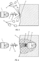
FIG. 3 depicts the effect of the impact of the exemplary projectile shown inFIG. 1 on a hard surface, wherein the projectile does not extend into the hard surface; -
FIG. 4 depicts another effect of the impact of the exemplary projectile shown inFIG. 1 on a soft surface, wherein the projectile penetrates into the soft surface; -
FIG. 5A depicts a front view of another exemplary projectile for ammunition of the present invention; -
FIG. 5B depicts a front view of yet another exemplary projectile for ammunition of the present invention; -
FIG. 6A depicts a top view of the exemplary projectile shown inFIG. 5A ; -
FIG. 6B depicts a top view of the exemplary projectile shown inFIG. 5B ; -
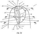
FIG. 7A depicts an exploded view of the exemplary notch of the exemplary projectile shown inFIG. 1 ; -
FIG. 7B depicts a partial cross-sectional view of the exemplary notch shown inFIG. 7A as viewed alongline 7B-7B; -
FIG. 7C depicts a partial cross-sectional view of the exemplary notch shown inFIG. 7A as viewed alongline 7C-7C; and -
FIG. 7D depicts a partial cross-sectional view of the exemplary notch shown inFIG. 7A as viewed along line 7D-7D. - To promote an understanding of the principles of the present invention, descriptions of specific embodiments of the invention follow and specific language is used to describe the specific embodiments.
- The present invention is directed to projectiles for ammunition, and ammunition for firearms. The present invention is further directed to methods of making projectiles for ammunition, and ammunition for firearms. The present invention is even further directed to methods of using projectiles for ammunition, and ammunition for firearms.
-
FIG. 1 depicts a front view of anexemplary projectile 1 for ammunition of the present invention. As shown inFIG. 1 ,exemplary projectile 1 has an outer geometry comprisingseveral notches 2 extending in a longitudinal direction (i.e., axial direction).Notches 2 are present in a number equal to or greater than two and are desirably disposed in such a manner as to avoid an imbalance of the rotation ofprojectile 1 about its dissectingaxis 3, which may cause a deviation of aflight path 9 such as shown inFIG. 3 . In some embodiments, the number ofnotches 2 is desirably three. In other embodiments, the number ofnotches 2 is desirably four. - As further shown in
FIG. 1 ,exemplary projectile 1 has a notch configuration that increases (i) an outer surface area ofogive end portion 5 ofprojectile 1, and (ii) a given length of an outer surface periphery extending along a line with in a plane normal to dissectingaxis 3. In some embodiments, at least one side (i.e., first notch surface portion 4) ofnotch 2 is inclined relative to anouter surface 51 ofogive end portion 5, so that, with the appropriate dimensions, thenotch 2 extends axially fromogive end portion 5 to alocation 52 betweenogive end portion 5 and acylindrical portion 6 ofprojectile 1, being surrounded (i.e., completely surrounded) byouter surface 51 ofogive end portion 5, and not occupycylindrical portion 6, which could negatively affect the caliber of the ammunition and the sealing required for propulsion ofprojectile 1 through a firearm. - Each
notch 2 may comprise firstnotch surface portion 4 in combination with a secondnotch surface portion 7, such asspherical surface 7.Spherical surface 7 makesnotch 2 structurally stronger so that when it hits asoft surface 8, it avoid the formation and propagation of cracks which decompose projectile 1 into small fragments. - In some embodiments, projectile 1 may be manufactured by injection molding a polymeric material (e.g., polyamide) filled with metal particles. In some embodiments, projectile 1 may be manufactured by sintering and/or machining with or without electrochemical coating. Desirably, in some embodiments, projectile 1 is manufactured with a base material that will not deform easily and decompose into fragments on a violent impact against a
hard surface 15 to ensure that it remains afrangible projectile 1 by definition. - As shown in
FIG. 3 , in some embodiments of the present invention, projectile 1 approaches ahard surface 15 after a shot, making atrajectory 9 with arotational movement 10 alongaxis 3 ofprojectile 1 so as to ensure stability during flight. On impact, energy ofprojectile 1 makes projectile 1 decompose intofragments 16, which are thrown in all directions producing only a small damagedarea 17 onhard surface 15. The production ofsuch fragments 16 prevents projectile 1 from ricocheting uncontrollably and reaching an unintended target. - As shown in
FIG. 4 , in some embodiments of the present invention, projectile 1 approaches asoft surface 8 upon firing, also following apath 9 and, at the same time, arotational movement 10 aroundaxis 3 ofprojectile 1 to ensure stability during flight. Upon impact on the target comprised ofsoft surface 8,penetration 11 occurs due to the projectile velocity and damping 12 of therotational movement 11. Damping 12 is due to the effect of thesoft surface 8 resistance cut bynotches 2 ofprojectile 1 as if it was a drill. Damping 12 will cause an increase in resistance ofprojectile 1 and an increase in the amount of damaged tissue, increasing the amount of transmitted energy (i.e., kinetic and rotational) and the size of the damagedarea 17 in the form of a temporary cavity. - In some embodiments, the bottom 61 of
projectile 1, opposite thetip 18 in the longitudinal direction ofaxis 3, may contain aconical geometry 19, also called "boat tail," as shown inFIG. 5B , to increase the aerodynamics ofprojectile 1. In other embodiments, the bottom 61 ofprojectile 1 may have adouble diameter 20, as shown inFIG. 5A , to fit the mounting of, for example, a polymer or composite casing. - The projectiles and ammunition of the present invention and methods of making and using projectiles and ammunition of the present invention are further described in the embodiments below.
- The present invention is further illustrated by the following examples, which are not to be construed in any way as imposing limitations upon the scope thereof. On the contrary, it is to be clearly understood that resort may be had to various other embodiments, modifications, and equivalents thereof which, after reading the description herein, may suggest themselves to those skilled in the art without departing from the present invention and/or the scope of the appended claims.
- Exemplary projectiles as shown in
FIGS. 1-7D were prepared using various projectile-forming steps. In some cases, exemplary projectiles such as shown inFIGS. 1-7D were prepared by injection molding polymer resin, such as a polyamide filled with copper particles, to form 9 mmcomposite projectiles 1. In other cases, exemplary projectiles such as shown inFIGS. 1-7D were prepared by a stamping process so as to formmetal projectiles 1 comprising copper or lead. - The resulting projectiles were incorporated into a metal casing or a composite casing, such as the composite casing disclosed in International Application Serial No.:
PCT/US12/71395, filed on December 12, 2013 and entitled "POLYMER-BASED COMPOSITE CASINGS AND AMMUNITION CONTAINING THE SAME, AND METHODS OF MAKING AND USING THE SAME". - The above procedure, or a variation thereof, was used to form ammunition suitable for use in a variety of commercially available rifles, pistols, machine and submachine guns, and air-guns (e.g., pistols and other hand guns, rifles, machine and submachine guns, etc.).
- It should be understood that although the above-described projectiles, ammunition and/or methods are described as "comprising" one or more components or steps, the above-described projectiles, ammunition and/or methods may "comprise," "consists of," or "consist essentially of' the above-described components, features or steps of the projectiles, ammunition and/or methods. Consequently, where the present invention, or a portion thereof, has been described with an open-ended term such as "comprising," it should be readily understood that (unless otherwise stated) the description of the present invention, or the portion thereof, should also be interpreted to describe the present invention, or a portion thereof, using the terms "consisting essentially of' or "consisting of' or variations thereof as discussed below.
- As used herein, the terms "comprises," "comprising," "includes," "including," "has," "having," "contains", "containing," "characterized by" or any other variation thereof, are intended to encompass a non-exclusive inclusion, subject to any limitation explicitly indicated otherwise, of the recited components. For example, a projectile, ammunition and/or method that "comprises" a list of elements (e.g., components, features, or steps) is not necessarily limited to only those elements (or components or steps), but may include other elements (or components or steps) not expressly listed or inherent to the projectile, ammunition and/or method.
- As used herein, the transitional phrases "consists of' and "consisting of' exclude any element, step, or component not specified. For example, "consists of' or "consisting of" used in a claim would limit the claim to the components, materials or steps specifically recited in the claim except for impurities ordinarily associated therewith (i.e., impurities within a given component). When the phrase "consists of" or "consisting of" appears in a clause of the body of a claim, rather than immediately following the preamble, the phrase "consists of" or "consisting of" limits only the elements (or components or steps) set forth in that clause; other elements (or components) are not excluded from the claim as a whole.
- As used herein, the transitional phrases "consists essentially of" and "consisting essentially of' are used to define a projectile, ammunition and/or method that includes materials, steps, features, components, or elements, in addition to those literally disclosed, provided that these additional materials, steps, features, components, or elements do not materially affect the basic and novel characteristic(s) of the claimed invention. The term "consisting essentially of' occupies a middle ground between "comprising" and "consisting of".
- Further, it should be understood that the herein-described projectiles, ammunition and/or methods may comprise, consist essentially of, or consist of any of the herein-described components, features and steps, as shown in the figures with or without any feature(s) not shown in the figures. In other words, in some embodiments, the projectiles, ammunition and/or methods of the present invention do not have any additional features other than those shown in the figures, and such additional features, not shown in the figures, are specifically excluded from the projectiles, ammunition and/or methods. In other embodiments, the projectiles, ammunition and/or methods of the present invention do have one or more additional features that are not shown in the figures.
Claims (15)
- A projectile (1) for ammunition, said projectile (1) comprising an outer profile geometry on an ogive-shaped impact end portion (5) thereof, said outer profile geometry comprising two or more notches (2) extending in (i) an axial, and (ii) parallel orientation relative to a dissecting axis (3) extending longitudinally through said impact end portion (5) of said projectile (1), wherein each notch (2) comprises notch surface portions (4,7) so as to increase (i) an overall outer surface area of said ogive end portion (5) of projectile (1), and (ii) a given length of an outer surface periphery (Sp ) extending along a line within a plane normal to said dissecting axis (3), whereby each notch (2) (a) is surrounded by an outer side surface (51) of said ogive-shaped impact end portion (5) of said projectile (1), and (b) is oriented at an angle (A) of greater than zero up to about 45° relative to said dissecting axis (3).
- The projectile (1) of claim 1, wherein each notch (2) comprises:a notch dissecting line (Lnd ) extending axially through and being centrally located within said notch (2),notch outer periphery points (PL ,PR ) along an outer notch perimeter (21) on opposite sides of said notch dissecting line (Lnd ), andright and left-hand line portions (22L ,22R ) of a normal line extending from said notch dissecting line (Lnd ) to each notch outer periphery point (PL ,PR ), wherein each of said right and left-hand line portions (22L ,22R ) (i) increases in length along at least a first portion of said notch dissecting line (Lnd ) and subsequently (ii) decreases in length along at least a second portion of said notch dissecting line (Lnd ) extending between an uppermost periphery portion (23) of said notch (2) and a lowermost periphery portion (24) of said notch (2).
- The projectile (1) of claim 1 or 2, wherein each notch (2) comprises:a notch depth dissecting line (Ldd ) extending axially through and being located along a path that represents a largest depth within said notch (2),notch outer periphery points (PL ,PR ) along an outer notch perimeter (21) on opposite sides of said notch depth dissecting line (Ldd ), andright and left-hand line portions (25L ,25R ) of a normal line extending from said notch depth dissecting line (Ldd ) to each notch outer periphery point (PL ,PR ), wherein each of said right and left-hand line portions (25L ,25R ) (i) increases in length along at least a first portion of said notch depth dissecting line (Ldd ) and subsequently (ii) decreases in length along at least a second portion of said notch depth dissecting line (Ldd ) extending between an uppermost periphery portion (23) of said notch (2) and a lowermost periphery portion (24) of said notch (2).
- The projectile (1) of claim 3, wherein said notch depth dissecting line (Ldd ) curves as said notch depth dissecting line (Ldd ) moves from said uppermost periphery portion (23) of said notch (2) to said lowermost periphery portion (24) of said notch (2).
- The projectile (1) of claim 3 or 4, wherein said notch depth dissecting line (Ldd ) has a J-shape or reverse J-shape as said notch depth dissecting line (Ldd ) moves from said uppermost periphery portion (23) of said notch (2) to said lowermost periphery portion (24) of said notch (2).
- The projectile (1) of any one of claims 3 to 5, wherein each notch (2) has (i) a first notch surface area (35) and a first depth grade (37) on one side of said notch depth dissecting line (Ldd ), and (ii) a second notch surface area (36) and a second depth grade (38) on an opposite side of said notch depth dissecting line (Ldd ), said first notch surface area (35) being smaller than said second notch surface area (36) and said first depth grade (37) being greater than said second depth grade (38).
- The projectile (1) of any one of claims 1 to 6, wherein said notch surface portions (4,7) comprise one or more cylindrically-shaped or spherically-shaped notch surface portions (4,7).
- The projectile (1) of any one of claims 1 to 7, wherein said two or more notches (2) comprise three notches (2) equally spaced from one another.
- The projectile (1) of any one of claims 1 to 8, wherein each notch (2) has a slightly inclined orientation relative to said dissecting axis (3), with each notch (2) being oriented at an angle (A) of from about 15° to about 30° relative to said dissecting axis (3).
- The projectile (1) of any one of claims 1 to 9, wherein said ogive-shaped impact end portion (5) extends from a projectile tip end (18) to a transition periphery (52) along said projectile (1), and said projectile (1) further comprises a cylindrical portion (6) extending from said transition periphery (52) to an opposite end (61) of said projectile (1).
- The projectile (1) of any one of claims 1 to 10, wherein said ogive-shaped impact end portion (5) comprises a polymeric matrix material filled with metal particles or a metal, wherein said metal is selected from brass, silver, lead, lead alloy, copper plated lead alloy, copper, or stainless steel.
- The projectile (1) of any one of claims 1 to 11, wherein an opposite end (61) of said projectile (1) has a truncated cone shape and/or a reduced diameter cylindrical shape.
- A composite or polymer casing comprising the projectile (1) of any one of claims 1 to 12 mounted therein.
- A method of using the projectile (1) for ammunition of any one of claims 1 to 12, said method comprising:positioning a composite or polymer or metal casing comprising the projectile (1) in a chamber of a projectile-firing weapon; andfiring the weapon.
- A method of using the projectile (1) for ammunition of any one of claims 1 to 12, said method comprising:positioning the projectile (1) in a chamber of a projectile-firing compressed air weapon; andfiring the weapon.
Applications Claiming Priority (2)
| Application Number | Priority Date | Filing Date | Title |
|---|---|---|---|
| ES201331387 | 2013-09-24 | ||
| PCT/US2014/057171 WO2015048102A1 (en) | 2013-09-24 | 2014-09-24 | Projectiles for ammunition and methods of making and using the same |
Publications (2)
| Publication Number | Publication Date |
|---|---|
| EP3049754A1 EP3049754A1 (en) | 2016-08-03 |
| EP3049754B1 true EP3049754B1 (en) | 2019-05-22 |
Family
ID=51663515
Family Applications (1)
| Application Number | Title | Priority Date | Filing Date |
|---|---|---|---|
| EP14781788.6A Active EP3049754B1 (en) | 2013-09-24 | 2014-09-24 | Projectiles for ammunition and methods of making and using the same |
Country Status (7)
| Country | Link |
|---|---|
| US (2) | US9841260B2 (en) |
| EP (1) | EP3049754B1 (en) |
| AU (1) | AU2014326809B2 (en) |
| BR (1) | BR112016006270B1 (en) |
| CA (1) | CA2924103C (en) |
| MY (1) | MY197336A (en) |
| WO (1) | WO2015048102A1 (en) |
Families Citing this family (14)
| Publication number | Priority date | Publication date | Assignee | Title |
|---|---|---|---|---|
| US20170184382A9 (en) * | 2010-11-10 | 2017-06-29 | True Velocity, Inc. | Metal injection molded projectile |
| EP4607141A3 (en) | 2014-04-30 | 2025-11-12 | G9 Holdings, LLC | Projectile with enhanced ballistics |
| USD1055200S1 (en) | 2014-04-30 | 2024-12-24 | G9 Holdings, Llc | Projectile |
| US10345085B2 (en) | 2017-01-20 | 2019-07-09 | Lehigh Defense, LLC | Projectile having leading surface standoffs |
| US10690464B2 (en) | 2017-04-28 | 2020-06-23 | Vista Outdoor Operations Llc | Cartridge with combined effects projectile |
| CA3071267A1 (en) | 2017-07-27 | 2019-01-31 | Timberghost Tactical, Llc | Small-arms ammunition with non-brass casing and non-lead projectile |
| US11821714B2 (en) | 2017-10-17 | 2023-11-21 | Smart Nanos, Llc | Multifunctional composite projectiles and methods of manufacturing the same |
| CA3079214A1 (en) | 2017-10-17 | 2019-04-25 | Smart Nanos, Llc | Multifunctional composite projectiles and methods of manufacturing the same |
| US12442628B2 (en) | 2017-10-17 | 2025-10-14 | Smart Nanos, Llc | Multifunctional composite projectiles and methods of manufacturing the same |
| EP3724594B1 (en) * | 2017-12-14 | 2023-11-29 | Quantum Ammunition, LLC | Projectiles for ammunition and methods of making and using the same |
| USD876578S1 (en) * | 2017-12-14 | 2020-02-25 | Quantum Ammunition, Llc | Projectile for ammunition |
| US10119780B1 (en) * | 2018-01-12 | 2018-11-06 | David Wayne Bergeron | Light gas gun projectile |
| US10969209B2 (en) | 2018-02-14 | 2021-04-06 | Olin Corporation | Segmenting pistol bullet |
| ES2753190A1 (en) * | 2019-10-16 | 2020-04-07 | Extreme Polymer Res S L | Projectile for firearms |
Family Cites Families (26)
| Publication number | Priority date | Publication date | Assignee | Title |
|---|---|---|---|---|
| US463922A (en) * | 1891-11-24 | Philip g | ||
| DE16742C (en) * | 1881-06-15 | 1882-01-11 | E. RlVE, Premier-Lieut. a. d. in Porta bei Minden | Devices on projectiles in order to set them in rotation through the opposing air resistance |
| DE167742C (en) | 1902-10-25 | 1906-02-13 | Rotating device for the workpiece in pilgrim step rolling mills with reciprocating rollers and fixed roller frame | |
| US1218546A (en) * | 1915-09-25 | 1917-03-06 | Walter R Gillis | Submarine torpedo. |
| US1596180A (en) * | 1918-08-16 | 1926-08-17 | Henderson Albert Ennis | Ordnance projectile |
| US1373322A (en) * | 1919-01-10 | 1921-03-29 | Freitas Antone | Projectile |
| DE563931C (en) * | 1931-01-06 | 1932-11-11 | Syndicat Vaproc | Floor with sliding steps that generate negative pressure |
| FR807118A (en) * | 1935-09-26 | 1937-01-05 | Ball with tip in hardened and tempered steel, provided with helical grooves | |
| US2356227A (en) * | 1940-08-27 | 1944-08-22 | Diehl Elias Stanley | Projectile |
| DE3064795D1 (en) * | 1979-03-10 | 1983-10-20 | Schirnecker Hans Ludwig | Projectile, e.g. for hunting, and method of manufacturing same |
| US4829904A (en) * | 1983-06-22 | 1989-05-16 | Branscomb Corporation N. V. | Ammunition round |
| HU197441B (en) * | 1983-06-22 | 1989-03-28 | Branscomb Corp Nv | Cartridge for guns |
| US4718348A (en) * | 1986-05-16 | 1988-01-12 | Ferrigno John E | Grooved projectiles |
| US5133261A (en) * | 1990-06-25 | 1992-07-28 | Kelsey Jr Charles C | Devel small arms bullet |
| US5237930A (en) | 1992-02-07 | 1993-08-24 | Snc Industrial Technologies, Inc. | Frangible practice ammunition |
| EP0769131A4 (en) | 1994-07-06 | 1998-06-03 | Lockheed Martin Energy Sys Inc | LEAD-FREE PROJECTILES HARMFUL TO THE ENVIRONMENT AND THEIR MANUFACTURING PROCESS |
| US6074454A (en) | 1996-07-11 | 2000-06-13 | Delta Frangible Ammunition, Llc | Lead-free frangible bullets and process for making same |
| US6090178A (en) | 1998-04-22 | 2000-07-18 | Sinterfire, Inc. | Frangible metal bullets, ammunition and method of making such articles |
| US6070532A (en) * | 1998-04-28 | 2000-06-06 | Olin Corporation | High accuracy projectile |
| US6546875B2 (en) | 2001-04-23 | 2003-04-15 | Ut-Battelle, Llc | Non-lead hollow point bullet |
| US7222573B2 (en) * | 2005-04-01 | 2007-05-29 | Pontieri James M | Aerodynamic air gun projectile |
| US20070151474A1 (en) * | 2005-10-27 | 2007-07-05 | Widener Charles D | Aerodynamic rotational stabilization techniques for projectiles |
| AU2012205378B2 (en) * | 2011-01-14 | 2015-12-03 | Pcp Tactical, Llc | High strength polymer-based cartridge casing and manufacturing method |
| EP2795236B1 (en) | 2011-12-22 | 2017-03-08 | Polycase Ammunition, LLC | Polymer-based composite casing and ammunition containing the same |
| US9200880B1 (en) * | 2012-03-09 | 2015-12-01 | Carolina PCA, LLC | Subsonic ammunication articles having a rigid outer casing or rigid inner core and methods for making the same |
| USD748220S1 (en) * | 2014-09-12 | 2016-01-26 | Lehigh Defense, LLC | Bullet |
-
2014
- 2014-09-24 US US15/023,477 patent/US9841260B2/en active Active
- 2014-09-24 MY MYPI2016000527A patent/MY197336A/en unknown
- 2014-09-24 CA CA2924103A patent/CA2924103C/en not_active Expired - Fee Related
- 2014-09-24 WO PCT/US2014/057171 patent/WO2015048102A1/en not_active Ceased
- 2014-09-24 AU AU2014326809A patent/AU2014326809B2/en not_active Ceased
- 2014-09-24 EP EP14781788.6A patent/EP3049754B1/en active Active
- 2014-09-24 BR BR112016006270-1A patent/BR112016006270B1/en not_active IP Right Cessation
-
2017
- 2017-08-04 US US15/668,732 patent/US10126105B2/en active Active
Non-Patent Citations (1)
| Title |
|---|
| None * |
Also Published As
| Publication number | Publication date |
|---|---|
| CA2924103C (en) | 2021-07-27 |
| MY197336A (en) | 2023-06-13 |
| BR112016006270A2 (en) | 2017-08-01 |
| US20160231093A1 (en) | 2016-08-11 |
| BR112016006270B1 (en) | 2021-01-26 |
| CA2924103A1 (en) | 2015-04-02 |
| US20180045496A1 (en) | 2018-02-15 |
| EP3049754A1 (en) | 2016-08-03 |
| AU2014326809B2 (en) | 2018-03-22 |
| AU2014326809A1 (en) | 2016-03-31 |
| WO2015048102A1 (en) | 2015-04-02 |
| US9841260B2 (en) | 2017-12-12 |
| US10126105B2 (en) | 2018-11-13 |
Similar Documents
| Publication | Publication Date | Title |
|---|---|---|
| US10126105B2 (en) | Projectiles for ammunition and methods of making and using the same | |
| US12050093B2 (en) | Projectile with enhanced ballistics | |
| CN108369083B (en) | Improved fragmentation projectile and method of making the same | |
| AU2023200529A1 (en) | Projectile with penetrator | |
| EP3724594B1 (en) | Projectiles for ammunition and methods of making and using the same | |
| CA2566450C (en) | Lead-free projectile | |
| WO2007061318A1 (en) | Armour penetrating projectile | |
| US20190033046A1 (en) | Small-arms ammunition with non-brass casing and non-lead projectile | |
| HK1234479B (en) | Projectile with enhanced ballistics | |
| HK1234479A1 (en) | Projectile with enhanced ballistics |
Legal Events
| Date | Code | Title | Description |
|---|---|---|---|
| PUAI | Public reference made under article 153(3) epc to a published international application that has entered the european phase |
Free format text: ORIGINAL CODE: 0009012 |
|
| 17P | Request for examination filed |
Effective date: 20160323 |
|
| AK | Designated contracting states |
Kind code of ref document: A1 Designated state(s): AL AT BE BG CH CY CZ DE DK EE ES FI FR GB GR HR HU IE IS IT LI LT LU LV MC MK MT NL NO PL PT RO RS SE SI SK SM TR |
|
| AX | Request for extension of the european patent |
Extension state: BA ME |
|
| RIN1 | Information on inventor provided before grant (corrected) |
Inventor name: MARIN, JUAN CARLOS Inventor name: JOHNSON, STEVEN ERIC Inventor name: LEMKE, PAUL |
|
| DAX | Request for extension of the european patent (deleted) | ||
| GRAP | Despatch of communication of intention to grant a patent |
Free format text: ORIGINAL CODE: EPIDOSNIGR1 |
|
| STAA | Information on the status of an ep patent application or granted ep patent |
Free format text: STATUS: GRANT OF PATENT IS INTENDED |
|
| RAP1 | Party data changed (applicant data changed or rights of an application transferred) |
Owner name: POLYONE CORPORATION |
|
| RAP1 | Party data changed (applicant data changed or rights of an application transferred) |
Owner name: QUANTUM AMMUNITION, LLC |
|
| INTG | Intention to grant announced |
Effective date: 20181219 |
|
| GRAS | Grant fee paid |
Free format text: ORIGINAL CODE: EPIDOSNIGR3 |
|
| GRAA | (expected) grant |
Free format text: ORIGINAL CODE: 0009210 |
|
| STAA | Information on the status of an ep patent application or granted ep patent |
Free format text: STATUS: THE PATENT HAS BEEN GRANTED |
|
| AK | Designated contracting states |
Kind code of ref document: B1 Designated state(s): AL AT BE BG CH CY CZ DE DK EE ES FI FR GB GR HR HU IE IS IT LI LT LU LV MC MK MT NL NO PL PT RO RS SE SI SK SM TR |
|
| REG | Reference to a national code |
Ref country code: GB Ref legal event code: FG4D |
|
| REG | Reference to a national code |
Ref country code: CH Ref legal event code: EP |
|
| REG | Reference to a national code |
Ref country code: IE Ref legal event code: FG4D |
|
| REG | Reference to a national code |
Ref country code: DE Ref legal event code: R096 Ref document number: 602014047299 Country of ref document: DE |
|
| REG | Reference to a national code |
Ref country code: AT Ref legal event code: REF Ref document number: 1136629 Country of ref document: AT Kind code of ref document: T Effective date: 20190615 |
|
| REG | Reference to a national code |
Ref country code: CH Ref legal event code: NV Representative=s name: BOVARD AG PATENT- UND MARKENANWAELTE, CH |
|
| REG | Reference to a national code |
Ref country code: NL Ref legal event code: MP Effective date: 20190522 |
|
| REG | Reference to a national code |
Ref country code: LT Ref legal event code: MG4D |
|
| PG25 | Lapsed in a contracting state [announced via postgrant information from national office to epo] |
Ref country code: NL Free format text: LAPSE BECAUSE OF FAILURE TO SUBMIT A TRANSLATION OF THE DESCRIPTION OR TO PAY THE FEE WITHIN THE PRESCRIBED TIME-LIMIT Effective date: 20190522 Ref country code: HR Free format text: LAPSE BECAUSE OF FAILURE TO SUBMIT A TRANSLATION OF THE DESCRIPTION OR TO PAY THE FEE WITHIN THE PRESCRIBED TIME-LIMIT Effective date: 20190522 Ref country code: SE Free format text: LAPSE BECAUSE OF FAILURE TO SUBMIT A TRANSLATION OF THE DESCRIPTION OR TO PAY THE FEE WITHIN THE PRESCRIBED TIME-LIMIT Effective date: 20190522 Ref country code: ES Free format text: LAPSE BECAUSE OF FAILURE TO SUBMIT A TRANSLATION OF THE DESCRIPTION OR TO PAY THE FEE WITHIN THE PRESCRIBED TIME-LIMIT Effective date: 20190522 Ref country code: LT Free format text: LAPSE BECAUSE OF FAILURE TO SUBMIT A TRANSLATION OF THE DESCRIPTION OR TO PAY THE FEE WITHIN THE PRESCRIBED TIME-LIMIT Effective date: 20190522 Ref country code: PT Free format text: LAPSE BECAUSE OF FAILURE TO SUBMIT A TRANSLATION OF THE DESCRIPTION OR TO PAY THE FEE WITHIN THE PRESCRIBED TIME-LIMIT Effective date: 20190922 Ref country code: NO Free format text: LAPSE BECAUSE OF FAILURE TO SUBMIT A TRANSLATION OF THE DESCRIPTION OR TO PAY THE FEE WITHIN THE PRESCRIBED TIME-LIMIT Effective date: 20190822 Ref country code: AL Free format text: LAPSE BECAUSE OF FAILURE TO SUBMIT A TRANSLATION OF THE DESCRIPTION OR TO PAY THE FEE WITHIN THE PRESCRIBED TIME-LIMIT Effective date: 20190522 Ref country code: FI Free format text: LAPSE BECAUSE OF FAILURE TO SUBMIT A TRANSLATION OF THE DESCRIPTION OR TO PAY THE FEE WITHIN THE PRESCRIBED TIME-LIMIT Effective date: 20190522 |
|
| PG25 | Lapsed in a contracting state [announced via postgrant information from national office to epo] |
Ref country code: BG Free format text: LAPSE BECAUSE OF FAILURE TO SUBMIT A TRANSLATION OF THE DESCRIPTION OR TO PAY THE FEE WITHIN THE PRESCRIBED TIME-LIMIT Effective date: 20190822 Ref country code: GR Free format text: LAPSE BECAUSE OF FAILURE TO SUBMIT A TRANSLATION OF THE DESCRIPTION OR TO PAY THE FEE WITHIN THE PRESCRIBED TIME-LIMIT Effective date: 20190823 Ref country code: LV Free format text: LAPSE BECAUSE OF FAILURE TO SUBMIT A TRANSLATION OF THE DESCRIPTION OR TO PAY THE FEE WITHIN THE PRESCRIBED TIME-LIMIT Effective date: 20190522 Ref country code: RS Free format text: LAPSE BECAUSE OF FAILURE TO SUBMIT A TRANSLATION OF THE DESCRIPTION OR TO PAY THE FEE WITHIN THE PRESCRIBED TIME-LIMIT Effective date: 20190522 |
|
| REG | Reference to a national code |
Ref country code: AT Ref legal event code: MK05 Ref document number: 1136629 Country of ref document: AT Kind code of ref document: T Effective date: 20190522 |
|
| PG25 | Lapsed in a contracting state [announced via postgrant information from national office to epo] |
Ref country code: DK Free format text: LAPSE BECAUSE OF FAILURE TO SUBMIT A TRANSLATION OF THE DESCRIPTION OR TO PAY THE FEE WITHIN THE PRESCRIBED TIME-LIMIT Effective date: 20190522 Ref country code: SK Free format text: LAPSE BECAUSE OF FAILURE TO SUBMIT A TRANSLATION OF THE DESCRIPTION OR TO PAY THE FEE WITHIN THE PRESCRIBED TIME-LIMIT Effective date: 20190522 Ref country code: RO Free format text: LAPSE BECAUSE OF FAILURE TO SUBMIT A TRANSLATION OF THE DESCRIPTION OR TO PAY THE FEE WITHIN THE PRESCRIBED TIME-LIMIT Effective date: 20190522 Ref country code: AT Free format text: LAPSE BECAUSE OF FAILURE TO SUBMIT A TRANSLATION OF THE DESCRIPTION OR TO PAY THE FEE WITHIN THE PRESCRIBED TIME-LIMIT Effective date: 20190522 Ref country code: EE Free format text: LAPSE BECAUSE OF FAILURE TO SUBMIT A TRANSLATION OF THE DESCRIPTION OR TO PAY THE FEE WITHIN THE PRESCRIBED TIME-LIMIT Effective date: 20190522 |
|
| REG | Reference to a national code |
Ref country code: DE Ref legal event code: R097 Ref document number: 602014047299 Country of ref document: DE |
|
| PG25 | Lapsed in a contracting state [announced via postgrant information from national office to epo] |
Ref country code: SM Free format text: LAPSE BECAUSE OF FAILURE TO SUBMIT A TRANSLATION OF THE DESCRIPTION OR TO PAY THE FEE WITHIN THE PRESCRIBED TIME-LIMIT Effective date: 20190522 |
|
| PLBE | No opposition filed within time limit |
Free format text: ORIGINAL CODE: 0009261 |
|
| STAA | Information on the status of an ep patent application or granted ep patent |
Free format text: STATUS: NO OPPOSITION FILED WITHIN TIME LIMIT |
|
| PG25 | Lapsed in a contracting state [announced via postgrant information from national office to epo] |
Ref country code: TR Free format text: LAPSE BECAUSE OF FAILURE TO SUBMIT A TRANSLATION OF THE DESCRIPTION OR TO PAY THE FEE WITHIN THE PRESCRIBED TIME-LIMIT Effective date: 20190522 |
|
| 26N | No opposition filed |
Effective date: 20200225 |
|
| PG25 | Lapsed in a contracting state [announced via postgrant information from national office to epo] |
Ref country code: PL Free format text: LAPSE BECAUSE OF FAILURE TO SUBMIT A TRANSLATION OF THE DESCRIPTION OR TO PAY THE FEE WITHIN THE PRESCRIBED TIME-LIMIT Effective date: 20190522 |
|
| PG25 | Lapsed in a contracting state [announced via postgrant information from national office to epo] |
Ref country code: MC Free format text: LAPSE BECAUSE OF FAILURE TO SUBMIT A TRANSLATION OF THE DESCRIPTION OR TO PAY THE FEE WITHIN THE PRESCRIBED TIME-LIMIT Effective date: 20190522 Ref country code: SI Free format text: LAPSE BECAUSE OF FAILURE TO SUBMIT A TRANSLATION OF THE DESCRIPTION OR TO PAY THE FEE WITHIN THE PRESCRIBED TIME-LIMIT Effective date: 20190522 |
|
| PG25 | Lapsed in a contracting state [announced via postgrant information from national office to epo] |
Ref country code: IE Free format text: LAPSE BECAUSE OF NON-PAYMENT OF DUE FEES Effective date: 20190924 Ref country code: LU Free format text: LAPSE BECAUSE OF NON-PAYMENT OF DUE FEES Effective date: 20190924 |
|
| REG | Reference to a national code |
Ref country code: BE Ref legal event code: MM Effective date: 20190930 |
|
| PG25 | Lapsed in a contracting state [announced via postgrant information from national office to epo] |
Ref country code: BE Free format text: LAPSE BECAUSE OF NON-PAYMENT OF DUE FEES Effective date: 20190930 |
|
| PG25 | Lapsed in a contracting state [announced via postgrant information from national office to epo] |
Ref country code: CY Free format text: LAPSE BECAUSE OF FAILURE TO SUBMIT A TRANSLATION OF THE DESCRIPTION OR TO PAY THE FEE WITHIN THE PRESCRIBED TIME-LIMIT Effective date: 20190522 |
|
| PG25 | Lapsed in a contracting state [announced via postgrant information from national office to epo] |
Ref country code: IS Free format text: LAPSE BECAUSE OF FAILURE TO SUBMIT A TRANSLATION OF THE DESCRIPTION OR TO PAY THE FEE WITHIN THE PRESCRIBED TIME-LIMIT Effective date: 20190922 |
|
| PG25 | Lapsed in a contracting state [announced via postgrant information from national office to epo] |
Ref country code: MT Free format text: LAPSE BECAUSE OF FAILURE TO SUBMIT A TRANSLATION OF THE DESCRIPTION OR TO PAY THE FEE WITHIN THE PRESCRIBED TIME-LIMIT Effective date: 20190522 Ref country code: HU Free format text: LAPSE BECAUSE OF FAILURE TO SUBMIT A TRANSLATION OF THE DESCRIPTION OR TO PAY THE FEE WITHIN THE PRESCRIBED TIME-LIMIT; INVALID AB INITIO Effective date: 20140924 |
|
| PGFP | Annual fee paid to national office [announced via postgrant information from national office to epo] |
Ref country code: CZ Payment date: 20210923 Year of fee payment: 8 Ref country code: FR Payment date: 20210922 Year of fee payment: 8 |
|
| PGFP | Annual fee paid to national office [announced via postgrant information from national office to epo] |
Ref country code: GB Payment date: 20210920 Year of fee payment: 8 |
|
| PG25 | Lapsed in a contracting state [announced via postgrant information from national office to epo] |
Ref country code: MK Free format text: LAPSE BECAUSE OF FAILURE TO SUBMIT A TRANSLATION OF THE DESCRIPTION OR TO PAY THE FEE WITHIN THE PRESCRIBED TIME-LIMIT Effective date: 20190522 |
|
| PG25 | Lapsed in a contracting state [announced via postgrant information from national office to epo] |
Ref country code: CZ Free format text: LAPSE BECAUSE OF NON-PAYMENT OF DUE FEES Effective date: 20220924 |
|
| GBPC | Gb: european patent ceased through non-payment of renewal fee |
Effective date: 20220924 |
|
| PG25 | Lapsed in a contracting state [announced via postgrant information from national office to epo] |
Ref country code: FR Free format text: LAPSE BECAUSE OF NON-PAYMENT OF DUE FEES Effective date: 20220930 |
|
| PG25 | Lapsed in a contracting state [announced via postgrant information from national office to epo] |
Ref country code: GB Free format text: LAPSE BECAUSE OF NON-PAYMENT OF DUE FEES Effective date: 20220924 |
|
| REG | Reference to a national code |
Ref country code: CH Ref legal event code: U11 Free format text: ST27 STATUS EVENT CODE: U-0-0-U10-U11 (AS PROVIDED BY THE NATIONAL OFFICE) Effective date: 20251001 |
|
| PGFP | Annual fee paid to national office [announced via postgrant information from national office to epo] |
Ref country code: DE Payment date: 20250730 Year of fee payment: 12 |
|
| PGFP | Annual fee paid to national office [announced via postgrant information from national office to epo] |
Ref country code: IT Payment date: 20250825 Year of fee payment: 12 |
|
| PGFP | Annual fee paid to national office [announced via postgrant information from national office to epo] |
Ref country code: CH Payment date: 20251001 Year of fee payment: 12 |