EP3049609B1 - System and method for optimally routing chemicals in a plant - Google Patents
System and method for optimally routing chemicals in a plant Download PDFInfo
- Publication number
- EP3049609B1 EP3049609B1 EP14799563.3A EP14799563A EP3049609B1 EP 3049609 B1 EP3049609 B1 EP 3049609B1 EP 14799563 A EP14799563 A EP 14799563A EP 3049609 B1 EP3049609 B1 EP 3049609B1
- Authority
- EP
- European Patent Office
- Prior art keywords
- control unit
- routing
- drilling fluid
- equipment
- chemicals
- Prior art date
- Legal status (The legal status is an assumption and is not a legal conclusion. Google has not performed a legal analysis and makes no representation as to the accuracy of the status listed.)
- Active
Links
Images


Classifications
-
- G—PHYSICS
- G05—CONTROLLING; REGULATING
- G05D—SYSTEMS FOR CONTROLLING OR REGULATING NON-ELECTRIC VARIABLES
- G05D7/00—Control of flow
- G05D7/06—Control of flow characterised by the use of electric means
- G05D7/0617—Control of flow characterised by the use of electric means specially adapted for fluid materials
- G05D7/0629—Control of flow characterised by the use of electric means specially adapted for fluid materials characterised by the type of regulator means
- G05D7/0635—Control of flow characterised by the use of electric means specially adapted for fluid materials characterised by the type of regulator means by action on throttling means
-
- B—PERFORMING OPERATIONS; TRANSPORTING
- B01—PHYSICAL OR CHEMICAL PROCESSES OR APPARATUS IN GENERAL
- B01F—MIXING, e.g. DISSOLVING, EMULSIFYING OR DISPERSING
- B01F35/00—Accessories for mixers; Auxiliary operations or auxiliary devices; Parts or details of general application
-
- E—FIXED CONSTRUCTIONS
- E21—EARTH OR ROCK DRILLING; MINING
- E21B—EARTH OR ROCK DRILLING; OBTAINING OIL, GAS, WATER, SOLUBLE OR MELTABLE MATERIALS OR A SLURRY OF MINERALS FROM WELLS
- E21B21/00—Methods or apparatus for flushing boreholes, e.g. by use of exhaust air from motor
- E21B21/06—Arrangements for treating drilling fluids outside the borehole
- E21B21/062—Arrangements for treating drilling fluids outside the borehole by mixing components
-
- E—FIXED CONSTRUCTIONS
- E21—EARTH OR ROCK DRILLING; MINING
- E21B—EARTH OR ROCK DRILLING; OBTAINING OIL, GAS, WATER, SOLUBLE OR MELTABLE MATERIALS OR A SLURRY OF MINERALS FROM WELLS
- E21B43/00—Methods or apparatus for obtaining oil, gas, water, soluble or meltable materials or a slurry of minerals from wells
- E21B43/25—Methods for stimulating production
- E21B43/26—Methods for stimulating production by forming crevices or fractures
- E21B43/2607—Surface equipment specially adapted for fracturing operations
-
- E—FIXED CONSTRUCTIONS
- E21—EARTH OR ROCK DRILLING; MINING
- E21B—EARTH OR ROCK DRILLING; OBTAINING OIL, GAS, WATER, SOLUBLE OR MELTABLE MATERIALS OR A SLURRY OF MINERALS FROM WELLS
- E21B44/00—Automatic control systems specially adapted for drilling operations, i.e. self-operating systems which function to carry out or modify a drilling operation without intervention of a human operator, e.g. computer-controlled drilling systems; Systems specially adapted for monitoring a plurality of drilling variables or conditions
-
- G—PHYSICS
- G05—CONTROLLING; REGULATING
- G05B—CONTROL OR REGULATING SYSTEMS IN GENERAL; FUNCTIONAL ELEMENTS OF SUCH SYSTEMS; MONITORING OR TESTING ARRANGEMENTS FOR SUCH SYSTEMS OR ELEMENTS
- G05B13/00—Adaptive control systems, i.e. systems automatically adjusting themselves to have a performance which is optimum according to some preassigned criterion
- G05B13/02—Adaptive control systems, i.e. systems automatically adjusting themselves to have a performance which is optimum according to some preassigned criterion electric
- G05B13/04—Adaptive control systems, i.e. systems automatically adjusting themselves to have a performance which is optimum according to some preassigned criterion electric involving the use of models or simulators
- G05B13/041—Adaptive control systems, i.e. systems automatically adjusting themselves to have a performance which is optimum according to some preassigned criterion electric involving the use of models or simulators in which a variable is automatically adjusted to optimise the performance
-
- G—PHYSICS
- G05—CONTROLLING; REGULATING
- G05B—CONTROL OR REGULATING SYSTEMS IN GENERAL; FUNCTIONAL ELEMENTS OF SUCH SYSTEMS; MONITORING OR TESTING ARRANGEMENTS FOR SUCH SYSTEMS OR ELEMENTS
- G05B19/00—Program-control systems
- G05B19/02—Program-control systems electric
-
- E—FIXED CONSTRUCTIONS
- E21—EARTH OR ROCK DRILLING; MINING
- E21B—EARTH OR ROCK DRILLING; OBTAINING OIL, GAS, WATER, SOLUBLE OR MELTABLE MATERIALS OR A SLURRY OF MINERALS FROM WELLS
- E21B2200/00—Special features related to earth drilling for obtaining oil, gas or water
- E21B2200/22—Fuzzy logic, artificial intelligence, neural networks or the like
-
- G—PHYSICS
- G05—CONTROLLING; REGULATING
- G05B—CONTROL OR REGULATING SYSTEMS IN GENERAL; FUNCTIONAL ELEMENTS OF SUCH SYSTEMS; MONITORING OR TESTING ARRANGEMENTS FOR SUCH SYSTEMS OR ELEMENTS
- G05B2219/00—Program-control systems
- G05B2219/30—Nc systems
- G05B2219/31—From computer integrated manufacturing till monitoring
- G05B2219/31382—Find shortest way, route
Definitions
- the present invention relates to a drilling fluid plant and a method for routing of chemicals in said drilling fluid plant
- Drilling Fluids are made up of many different chemicals (additives); some in powder form and others in liquid form. The composition of chemicals varies greatly. Drilling fluid plants contain a complex matrix of tanks, pipes, valves, pumps, mixers etc. These are used for storing and transferring different chemicals from one place, a source, to another, a destination, when required and to mix the different chemicals together to achieve a homogenous drilling fluid with the necessary properties needed at any given time.
- chemicals are routed in a manual or semiautomatic way, meaning the operator needs to plan what route the chemicals should take from the source, such as a storage tank, to a destination, such as a mixing tank, without interfering with other ongoing processes. Thereafter all the equipment on the route needs to be operated individually in a given order. In some cases there may be static/fixed routes available where a process control unit has logics to operate specific equipment along the route.
- the operator Before starting a transfer of chemicals, the operator must first plan which route the chemicals should take. The operator needs to subjectively make several critical considerations so as to decide if there are any available transfer routes, whether a fast transfer and/or a maximum throughput is required, whether any equipment should be avoided, whether any equipment must be used (for instance a specific pump, mixer etc.) and whether a transfer along the planned route in any way will interfere with an ongoing transfer. Based on these and other considerations the operator needs to choose an optimum route/path for the chemical transfer. After choosing the optimum route, the operator also needs to consider if any equipment needs be executed in a specific order. When the transfer is ongoing, the operator further needs to constantly and carefully monitor the progress of the chemical transfer so as to detect any deviation, such as equipment failure, from a normal operation. In case of a deviation, the operator then needs to stop the ongoing operation by shutting down equipment, potentially in a required order, and then re-plan.
- the flexibility of the transfer system is significantly reduced as is the number of available routes.
- One route may be optimal, or near optimal, under normal operating conditions, but in the case of a deviation there may be only a few, if any, alternatives for the operator.
- the invention has for its object to remedy or to reduce at least one of the drawbacks of the prior art, or at least provide a useful alternative to prior art.
- Equipment will refer to any means needed to store, transfer and mix chemicals as well as instrumentation used for monitoring process values. It may be valves, motors, pumps, mixers, tanks, level transmitters etc. Equipment may also be composite means, such as machinery, consisting of more than on piece of equipment.
- Graph shall be understood as a representation of a set of objects where some pairs of objects are connected by links.
- the interconnected objects are represented by mathematical abstractions called vertices/nodes, and the links that connect some pairs of vertices are called edges.
- the graphs are typically depicted in diagrammatic form as a set of squares rectangles and ellipses for the vertices, joined by lines or curves for the edges.
- the vertices represent a piece of equipment.
- the edges represent the connectivity between vertices.
- the edges may be directed, implying that the edges have specific direction associated with them, or undirected, implying that the edges do not have a specific direction associated with them.
- the edges will typically represent piping. Directed edges are normally shown by arrows on the graph indicating the direction of flow of chemicals.
- Each edge has a cost/weight associated with it. The cost may be a fixed value or calculated based on pipe length, diameter, inclination, bend, etc. Different transfer operations with different requirements and chemicals involved may also set different weights on one edge. The weight may change dynamically.
- a shortest path problem is the task of finding a path between two vertices which minimizes the sum of weights of its constituent edges.
- a widest path problem often referred to as a bottleneck shortest path problem, is the task of finding a path between two designated vertices in a weighted graph that maximizes the weight of the minimum-weight edge in the path.
- an optimum path problem is solved for finding a path between a source and a destination in a chemical plant.
- the task of finding an optimum path is not necessarily the task of finding a shortest or widest path problem, even if it might be.
- the optimum path will depend on the specific operation in question, and may be a shortest path, e.g. minimum pipe length, minimum number of valves involved, maximum throughput, e.g. widest diameter and/or most powerful pumps etc., maximum resource utilization, least interference with other ongoing processes.
- One purpose of the present invention is to provide a fault tolerant automation of the process of transferring chemicals from a source to a destination by finding the optimum path therebetween while managing the equipment involved.
- Drilling fluid plant with automatic routing of chemicals comprising:
- the process control unit may be one or more PLCs and/or microcontrollers and/or computers or the like, adapted to control and/or communicate with one or more of said plurality of equipment.
- the process control unit may be connected to equipment via inputs and outputs and may contain logic to operate the equipment depending on feedback from the system and/or from an operator.
- the source and destination in one specific embodiment may be the same piece of equipment, for instance a storage tank, since in some situations it may be necessary to circulate and mix up drilling fluids due to sedimentation.
- the drilling fluid may therefore be transferred back to the source tank after mixing, whereby the storage tank may be both the source and the destination.
- the drilling fluid plant may comprise a plurality of sources and/or destinations.
- a typical drilling fluid plant may comprise a large number of pressure tanks, storage tanks, pumps, mixers, pipes etc. The more complex the drilling fluid plant, the more important it will be to be able to automatize at least parts of the transfer process.
- the routing control unit may thus be provided with a graph model depicting one or more of said plurality of equipment and one or more paths therebetween.
- the graph model may include a large number of equipment, including a plurality of sources, destinations and paths therebetween.
- the representation of sources, destinations, paths and appurtenant equipment in a graph model may enable the use of graph search algorithms to find optimum paths.
- said routing control unit may comprise a routing module, a business logic module and a user interface module.
- the routing module may be a platform-independent application, i.e. it may run on Windows, MAC, Linux etc., written in programming language such as C++, Java or C#.
- the routing module may further comprise different building blocks such as a communication interface enabling communication with external components, such as other parts of the routing control unit, including the business logic module and the user interface module, and the process control unit.
- the routing module may also comprise a path-finding module for harnessing various algorithms to calculate an optimized transferring path using information from the business logic module and the process control unit.
- the routing module may further comprise a request processor for receiving, processing and tracking requests, typically manually input form the user interface module or from the process control unit.
- the request processor may further operate equipment, via the process control unit, and monitor status of the equipment.
- the Process control unit may be adapted for bi-directional communication with the routing control unit. This implies that the process control unit may not only supply feedback to the routing control unit but also receive commands from the routing control unit. In such an embodiment the user interface module may be bypassed and the routing control unit may receive commands directly from the process control unit.
- the business logic module may contain a set of configurations, rules and a representation of the plant.
- the business logic module may further encode the connectivity between the different equipment, such as valves, operating order, and other configurations.
- the business logic module may be a database, such as MySQL/SQLite or a flat-file, such as in XML/JSON format.
- the graph model discussed above may be a part of the business logic module. In the graph model, properties may be put on edges and vertices, and costs/weights may be assigned to each edge. The graph model may also implement constraints restricting the allowable paths.
- An operator may communicate with the drilling fluid plant through a user interface module, through which commands may be entered and feedback received.
- a drilling fluid plant according to the invention may be provided with a plurality of interface modules.
- system may comprise a communication layer through which said routing control unit may communicate with said process control unit.
- the communication layer may enable communication between the routing control unit and the process control unit and the various parts and modules thereof.
- the communication layer may comprise one or more of the following:
- the communication layer may to allow for retro-fitting, i.e. it may allow installation of a routing control unit on top of an already installed process control unit in a drilling fluid plant.
- a process control unit may already be installed on a rig or in a plant and it may be desirable to install a routing system "on top of this" later on.
- the configuration with the communication layer may enable such an upgrade without having to do significant changes to the existing process control system. Modularizing the drilling fluid plant also makes it easier to develop the various components independently and if need be swap out with alternative solutions at a later stage.
- the communication layer may also allow the various components to be run across different machines.
- one or more constraints may be built into said routing control unit, inhibiting the use of one or more possible paths or parts of possible paths.
- the constraints will typically, but not necessarily, be built into the business logic module to extend the logic. Constraints may be process specific. For instance, during certain processes it may be desirable to limit or avoid the use of high-angular pipe bends so as to avoid excessive abrasion and wear of pipes. This may be of particular importance when transferring a chemical comprising non-fluid material, such as drilling mud powder.
- the routing control unit may include a storage unit for storing/caching information about previously calculated optimum paths between said source and said destination. This may simplify re-use of previously and frequently performed transfer operations.
- a drilling fluid plant according the first aspect of the invention may contain algorithms, logics and interfaces to be able to fulfil an objective of the invention.
- the drilling fluid plant may be designed to use adaptive routing driven by business logic rules, which may be plant specific, and include information on pipe arrangement, equipment count, distances.
- the drilling fluid plant according to the invention may calculate, control and perform multiple, simultaneous chemical transfer operations.
- the invention relates more particularly to a method for automatic routing of chemicals by means of a drilling fluid plant according to first aspect of the invention, the method including the steps of:
- the transferring may be executed by the routing control unit sending instructions to the process control unit, the process control unit further regulating the necessary equipment, such as pumps, valves, mixers etc., so as to execute the transfer, and preferably also monitor the transfer.
- the necessary equipment such as pumps, valves, mixers etc.
- the step of finding the optimum path between said source and said destination may include the step of depicting one or more sources, one or more destinations and one or more paths in a graph model in the routing control unit. Representing a chemical plant in a graph model enables the use of graph search algorithms to optimize the chemical transfer processes.
- the search algorithm may be implemented in the routing module of the routing control unit.
- the step of implementing a graph search algorithm may include using a shortest path algorithm, such as Dijkestra's shortest path algorithm.
- a shortest path algorithm such as Dijkestra's shortest path algorithm.
- Other shortest path algorithms such as Gabow's algorithm or the Bellman-Ford algorithm, also may be useful in certain embodiments.
- the step of implementing a graph search algorithm may include the step of using a resource-constrained shortest path algorithm.
- the resource-constrained shortest path algorithm may be implemented by running a shortest path search after pruning edges that violate a certain set of constraints.
- constraints may include avoiding transfer pipes with a diameter lower than a certain limit so as to optimize throughput or it may include avoiding high-angular pipe bends for reasons discussed above.
- the step of implementing a graph search algorithm may include implementing a path search algorithm minimizing interferences (PSAMI) using a Folk Fulkerson Algorithm, implying that the algorithm may maximize flow while minimizing interference between simultaneously ongoing transfer processes.
- PSAMI path search algorithm minimizing interferences
- the step of finding an optimum path between said source and said destination may further include the step of manually supplying information to routing control unit.
- This may typically be information about the specific operation to be executed, but also information about restrictions or specific know-how about mixing of chemicals or the chemical plant etc.
- the step of transferring the chemicals may include operating equipment along said optimum path in a pre-determined order.
- the equipment to function optimally it may be necessary to start and/or stop the equipment in a predetermined order. It may for instance be necessary to open a specific valve prior to starting an appurtenant pump so as to not run the pump dry.
- the method may include the step of simultaneously transferring chemicals along multiple paths between multiple sources and multiple destinations in the drilling fluid plant.
- the routing control unit may be configured to calculate and operate multiple chemical transfer processes at the same time, which may significantly increase the efficiency of a drilling fluid plant according to the present invention.
- the method may include the step of adapting an ongoing transfer of chemicals between said source and said destination by means of the routing control unit, based on feedback from the process control unit.
- the feedback from the process control unit may be feedback from one or more PLCs or the like about the status of one or more of said plurality of equipment. It may be information about failure or the need for maintenance in a piece of equipment, from which information about a new constraint is added to the routing control unit, for instance to the business logic module, whereby an alternative path may need to be calculated on the fly.
- the method may further include the step of storing/caching data related ongoing and completed processes. This may enable the use of data mining to optimize use of a drilling fluid plant according to the invention, for instance to log the use of individual equipment to predict maintenance circles.
- caching may be active, implying that the data is maintained in a shared location, such as a PLC memory or another computer, or the caching may be inactive, implying that data is maintained in a hard-drive, where back-up is taken at regular intervals.
- the inactive, hard drive-stored data may be used to build active data.
- the drilling fluid plant may be designed so that the different routing control units and/or routing modules share information through the communications layer. If a routing means fails, another routing means may take over.
- the routing control unit may be adapted to perform load balancing so as to distribute a workload evenly across two or more computers, network links, CPUs, hard-drives or other resources, in order to optimize resource utilization, maximize throughput, minimize response time and avoid overload.
- load balancing may be utilized in the routing control unit: Multiple threads/processes may be created, each capable of managing the complete routing cycle/process. Multiple requests arriving at the same time may be processed by any routing control unit with available resources.
- the different control units may be given unique tasks, e.g.
- a CPU1 may find the optimum route, a CPU2 may start/stop equipment in an assigned order, a CPU3 may ensure that feedback is correct and a CPU4 may be a master controller that orchestrates CPU1-3.
- the routing control unit may delegate composite object sequencing /handling to the process control unit or to an external controller.
- the routing control unit may handle individual valves while it delegates individual start/stop of equipment within composite objects like a machine to the process control unit.
- the routing control unit may request the machine to start or stop and may monitor the equipment/machine status and respond accordingly, as may be defined by the business logic module.
- the routing control unit may want to wait before auto-routing the remaining equipment until it has received an appropriate feedback (e.g. a "running" feedback) from the process control unit.
- an appropriate feedback e.g. a "running" feedback
- the method may comprise the step of letting the drilling fluid plant according to the first aspect of the invention, take over an already ongoing transfer process. This may make it possible to start the drilling fluid plant manually and then let the routing control unit take over the transfer process after it has been initiated.
- the invention in a third aspect relates to a computer program product comprising instructions for causing a processor to perform the method according to second aspect of the invention.
- Figure 1 shows an overview of a drilling fluid plant 1.
- the figure is shown as an example of the complexity of a real-life plant for the mixing and treatment of drilling fluids. It is, however, beyond the scope of the present description to describe this plant in detail. Only a few parts of the drilling fluid plant 1 will be described herein.
- Reference number 3 denotes a plurality of sources in the form of storage pressure tanks for bulk powder barite and cement.
- a plurality of pipes 7 run from the storage pressure tanks 3 to a plurality of destinations 5 exemplified in the form of mud storage tanks.
- the bulk powder storage tanks 3 and the mud storage tanks 5 are connected to a mud mixing system 13 via the plurality of pipes 7 and a plurality of valves and pumps 11.
- valves are not shown in Figure 1 for simplicity, but a drilling fluid plant 1 like the one shown in the figure will typically be provided with in the order of 150 valves which may be used to direct the flow of chemicals through the plurality of pipes 7 along a designated path.
- the mud mixing system 13 will receive different chemicals, at least some of which comes from the storage pressure tanks 3, mix them together and transfer the mixture to the mud storage tanks 5.
- FIG 2 the internal structure of a routing control unit 2 and its connection to a process control unit 4 is shown.
- the routing control unit 2 is shown comprising a routing module 21, a business logic module 23 and a user interface module 25.
- the constituents of the routing control unit 2 were discussed above and will not be repeated here.
- Both the constituents of the routing control unit 2 and the process control unit 4 communicate via a communication layer 6.
- the communication layer 6 may be regarded as the back-bone of the control units 2, 4 which allows the various components to access and share information.
- the business logic module 23 contains a set of configurations, rules and a graph representation of the plant.
- the process control unit 4 controls and monitors the various pieces of equipment in the plant.
- the user interface module 25 allows an operator to give commands and receive feedback.
- the routing module 21 automatically finds the optimum path based on information in the business logic module 23, commands given by an operator and by constantly monitoring the status of equipment through the process control unit 4.
- the order in which equipment is started and/or stopped must sometimes be controlled.
- FIG. 3 shows a simplified example of a directional graph model representation of chemical plant.
- the graph model shows two tanks, T1 and T2, representing a source 3 and a destination 5, respectively.
- Below the first tank T1 are located two discharge valves v1.1 and v1.2 and below the second tank T2 are also located two discharge valve v1x.1 and v1x.2.
- On top of the first tank T1 are located two filling valves v1.3 and v1.4 while two more filling valves v1x.3 and v1x.4 are located above the second tank T2.
- the graph model further includes valves V101, V201, V100 and V200 and pumps P1 and P2.
- the lines between the equipment, i.e. between the valves and pumps, indicate pipes that connect the equipment.
- the arrows indicate the direction of flow while the number on each line indicates the cost of the connection. The higher the number, the higher the cost associated with a specific flow.
- Transferring a chemical from the first tank T1 to the second tank T2 may be done by engaging different sets of valves and pumps and thus directing the flow of chemicals along different paths. Possible paths are:
- the routing control unit 2 will choose the P1 in the example above since it is the shortest path, i.e. it has the lowest cost associated with it.
- the routing control unit 2 controls the applicable equipment. This may be by done controlling all the equipment individually and/or in combination with composite object handling, implying that the process control unit 4 may for example have logics for control of a set of equipment e.g. a machine, a pump with applicable valves etc. It also ensures that any equipment on or adjacent to the chosen path/route is flagged as "occupied”. This is to ensure that there is no interference with any other ongoing flow of chemicals. As an example, when the discharge valve V1.1 on the first tank T1 is opened, the other discharge valve V1.2 is closed and both are flagged as "occupied”.
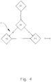
- Constraints are a set of rules which extend business logic module 23. These rules restrict the formation of a routing-path by inhibiting the relation between nodes, i.e. equipment, in a specific order.
- a valve V1 is connected to a valve V2.
- V2 is further connected to both a valve V3 and a valve V4 via different routes, while V4 is connected to V3.
- the connection line between V2 and V4 is dashed, implying that this is a constraint C.
- a valid path is V1 ⁇ V2 ⁇ V3 as there are no constraints C along this path. Paths V1 ⁇ V2 ⁇ V4 and V1 ⁇ V2 ⁇ V3 ⁇ V4 are not valid as the constraint C is restricting any path going to V4 after it has "passed by" V2, i.e. formation of a path is not allowed if V2 appears before V4 in the path.
Landscapes
- Engineering & Computer Science (AREA)
- Life Sciences & Earth Sciences (AREA)
- Mining & Mineral Resources (AREA)
- Geology (AREA)
- Physics & Mathematics (AREA)
- General Life Sciences & Earth Sciences (AREA)
- Fluid Mechanics (AREA)
- Environmental & Geological Engineering (AREA)
- Geochemistry & Mineralogy (AREA)
- General Physics & Mathematics (AREA)
- Automation & Control Theory (AREA)
- Mechanical Engineering (AREA)
- Medical Informatics (AREA)
- Health & Medical Sciences (AREA)
- Artificial Intelligence (AREA)
- Computer Vision & Pattern Recognition (AREA)
- Evolutionary Computation (AREA)
- Software Systems (AREA)
- Chemical & Material Sciences (AREA)
- Chemical Kinetics & Catalysis (AREA)
- Programmable Controllers (AREA)
- Pipeline Systems (AREA)
- Physical Or Chemical Processes And Apparatus (AREA)
Description
- The present invention relates to a drilling fluid plant and a method for routing of chemicals in said drilling fluid plant
- Drilling Fluids are made up of many different chemicals (additives); some in powder form and others in liquid form. The composition of chemicals varies greatly. Drilling fluid plants contain a complex matrix of tanks, pipes, valves, pumps, mixers etc. These are used for storing and transferring different chemicals from one place, a source, to another, a destination, when required and to mix the different chemicals together to achieve a homogenous drilling fluid with the necessary properties needed at any given time.
- On drilling fluid plants according to the prior art, chemicals are routed in a manual or semiautomatic way, meaning the operator needs to plan what route the chemicals should take from the source, such as a storage tank, to a destination, such as a mixing tank, without interfering with other ongoing processes. Thereafter all the equipment on the route needs to be operated individually in a given order. In some cases there may be static/fixed routes available where a process control unit has logics to operate specific equipment along the route.
- Since the amount of valves, pumps, mixers etc. that need to be engaged typically is large and spread out over a large area, and thus part of a complex matrix of piping, routing of chemicals from a source to a destination may be a complex and time-consuming process requiring high skills from an operator. Finding an optimum path between source and destination is particularly complicated, especially when multiple simultaneous routings /parallel flows are required. Erroneous or sub-optimal routing of chemicals is therefore quite common, which may result in unwanted situations such as contamination of fluids, the need to discard chemicals, high cost, negative HSE issues, poor drilling efficiency, poor product quality, drilling-downtime, and inferior personnel safety.
- Before starting a transfer of chemicals, the operator must first plan which route the chemicals should take. The operator needs to subjectively make several critical considerations so as to decide if there are any available transfer routes, whether a fast transfer and/or a maximum throughput is required, whether any equipment should be avoided, whether any equipment must be used (for instance a specific pump, mixer etc.) and whether a transfer along the planned route in any way will interfere with an ongoing transfer. Based on these and other considerations the operator needs to choose an optimum route/path for the chemical transfer. After choosing the optimum route, the operator also needs to consider if any equipment needs be executed in a specific order. When the transfer is ongoing, the operator further needs to constantly and carefully monitor the progress of the chemical transfer so as to detect any deviation, such as equipment failure, from a normal operation. In case of a deviation, the operator then needs to stop the ongoing operation by shutting down equipment, potentially in a required order, and then re-plan.
- With the potential complexity of a chemical plant, the amount of manual involvement in a chemical transfer process makes it highly probable that the transfer process will be sub-optimal or even incorrect, thus leading to potential inefficient transfer, excessive wear of equipment, high equipment down-time, high chemical contamination and excessive waste.
- By dividing the plant into a number of fixed, non-dynamic, chemical transfer routes, the flexibility of the transfer system is significantly reduced as is the number of available routes. One route may be optimal, or near optimal, under normal operating conditions, but in the case of a deviation there may be only a few, if any, alternatives for the operator.
- The article "Coordinator MPC for maximizing plant throughput" published in "Modeling, Identification, and Control" on July 1, 2008 pages 103-115 discloses system and a process for maximizing fluid throughput in a plant. The article is related to maximizing plant throughput, which has been shown to be the same as maximizing flow through the bottlenecks of the plant. This insight has led to the simplification of not having to monitor the plant at a detailed level.
- The article "Path Search Algorithm for Connections with Pumps in Crude Oil Pipe Networks" was published as a pre-print for the International Federation of Automatic Control (IFAC) World Congress in Milan August 28 - September 2, 2011 discloses the use of path search algorithms used to optimize transfer of crude oil in pipe networks.
- The article "Path and equipment allocation for multiple, concurrent processes on networked process plant units" published in "COMPUTERS & CHEMICAL ENGINEERING", vol. 20, no. 9, on September 1, 1996 addresses the path and equipment allocation problem for batch processes in the context graph theory.
- The invention has for its object to remedy or to reduce at least one of the drawbacks of the prior art, or at least provide a useful alternative to prior art.
- The object is achieved through features, which are specified in the description below and in the claims that follow.
- The invention is defined by the independent patent claims. The dependent claims define advantageous embodiments of the invention.
- Hereinafter definitions of some expressions used in the present description is given, which may contribute to simplify understanding of the invention.
- "Equipment" will refer to any means needed to store, transfer and mix chemicals as well as instrumentation used for monitoring process values. It may be valves, motors, pumps, mixers, tanks, level transmitters etc. Equipment may also be composite means, such as machinery, consisting of more than on piece of equipment.
- "Graph" shall be understood as a representation of a set of objects where some pairs of objects are connected by links. The interconnected objects are represented by mathematical abstractions called vertices/nodes, and the links that connect some pairs of vertices are called edges. Herein, the graphs are typically depicted in diagrammatic form as a set of squares rectangles and ellipses for the vertices, joined by lines or curves for the edges.
- On a graph-model of a drilling fluid plant, the vertices represent a piece of equipment. Further, the edges represent the connectivity between vertices. The edges may be directed, implying that the edges have specific direction associated with them, or undirected, implying that the edges do not have a specific direction associated with them. On a graph model of a drilling fluid plant the edges will typically represent piping. Directed edges are normally shown by arrows on the graph indicating the direction of flow of chemicals. Each edge has a cost/weight associated with it. The cost may be a fixed value or calculated based on pipe length, diameter, inclination, bend, etc. Different transfer operations with different requirements and chemicals involved may also set different weights on one edge. The weight may change dynamically.
- In graph theory, a shortest path problem is the task of finding a path between two vertices which minimizes the sum of weights of its constituent edges. A widest path problem, often referred to as a bottleneck shortest path problem, is the task of finding a path between two designated vertices in a weighted graph that maximizes the weight of the minimum-weight edge in the path.
- According to the present invention an optimum path problem is solved for finding a path between a source and a destination in a chemical plant. The task of finding an optimum path is not necessarily the task of finding a shortest or widest path problem, even if it might be. The optimum path will depend on the specific operation in question, and may be a shortest path, e.g. minimum pipe length, minimum number of valves involved, maximum throughput, e.g. widest diameter and/or most powerful pumps etc., maximum resource utilization, least interference with other ongoing processes.
- One purpose of the present invention is to provide a fault tolerant automation of the process of transferring chemicals from a source to a destination by finding the optimum path therebetween while managing the equipment involved.
- Drilling fluid plant with automatic routing of chemicals, the drilling fluid plant comprising:
- a plurality of equipment, including a source and a destination;
- one or more possible paths between said source and said destination;
- a process control unit being adapted to communicate with, to control and monitor said plurality of equipment; and
- a routing control unit, the routing control unit being adapted to communicate with the process control unit, and the routing control unit being provided with a graph search algorithm for finding an optimum path between said source and said destination based at least partially on feedback from said process control unit, wherein said routing control unit is provided with a graph model depicting said one or more pieces of equipment and one or more paths therebetween.
- The process control unit may be one or more PLCs and/or microcontrollers and/or computers or the like, adapted to control and/or communicate with one or more of said plurality of equipment. The process control unit may be connected to equipment via inputs and outputs and may contain logic to operate the equipment depending on feedback from the system and/or from an operator.
- It should be noted that the source and destination in one specific embodiment may be the same piece of equipment, for instance a storage tank, since in some situations it may be necessary to circulate and mix up drilling fluids due to sedimentation. The drilling fluid may therefore be transferred back to the source tank after mixing, whereby the storage tank may be both the source and the destination.
- In one embodiment the drilling fluid plant may comprise a plurality of sources and/or destinations. A typical drilling fluid plant may comprise a large number of pressure tanks, storage tanks, pumps, mixers, pipes etc. The more complex the drilling fluid plant, the more important it will be to be able to automatize at least parts of the transfer process. In one embodiment the routing control unit may thus be provided with a graph model depicting one or more of said plurality of equipment and one or more paths therebetween. Typically the graph model may include a large number of equipment, including a plurality of sources, destinations and paths therebetween. The representation of sources, destinations, paths and appurtenant equipment in a graph model may enable the use of graph search algorithms to find optimum paths.
- In one embodiment said routing control unit may comprise a routing module, a business logic module and a user interface module.
- The routing module may be a platform-independent application, i.e. it may run on Windows, MAC, Linux etc., written in programming language such as C++, Java or C#. The routing module may further comprise different building blocks such as a communication interface enabling communication with external components, such as other parts of the routing control unit, including the business logic module and the user interface module, and the process control unit. The routing module may also comprise a path-finding module for harnessing various algorithms to calculate an optimized transferring path using information from the business logic module and the process control unit. The routing module may further comprise a request processor for receiving, processing and tracking requests, typically manually input form the user interface module or from the process control unit. The request processor may further operate equipment, via the process control unit, and monitor status of the equipment.
- The Process control unit may be adapted for bi-directional communication with the routing control unit. This implies that the process control unit may not only supply feedback to the routing control unit but also receive commands from the routing control unit. In such an embodiment the user interface module may be bypassed and the routing control unit may receive commands directly from the process control unit.
- The business logic module may contain a set of configurations, rules and a representation of the plant. The business logic module may further encode the connectivity between the different equipment, such as valves, operating order, and other configurations. The business logic module may be a database, such as MySQL/SQLite or a flat-file, such as in XML/JSON format. The graph model discussed above may be a part of the business logic module. In the graph model, properties may be put on edges and vertices, and costs/weights may be assigned to each edge. The graph model may also implement constraints restricting the allowable paths.
- An operator may communicate with the drilling fluid plant through a user interface module, through which commands may be entered and feedback received. A drilling fluid plant according to the invention may be provided with a plurality of interface modules.
- In one embodiment the system may comprise a communication layer through which said routing control unit may communicate with said process control unit. The communication layer may enable communication between the routing control unit and the process control unit and the various parts and modules thereof. In one embodiment the communication layer may comprise one or more of the following:
- IPC methods, such as DDE/OPC/socket/Message passing/MPI/Shared memory/ TCP/UDP, etc; and
- cloud computing, such as a distributed system with load-balancing which is redundant, fault tolerant and with distributed transparency.
- The communication layer may to allow for retro-fitting, i.e. it may allow installation of a routing control unit on top of an already installed process control unit in a drilling fluid plant. As an example, a process control unit may already be installed on a rig or in a plant and it may be desirable to install a routing system "on top of this" later on. The configuration with the communication layer may enable such an upgrade without having to do significant changes to the existing process control system. Modularizing the drilling fluid plant also makes it easier to develop the various components independently and if need be swap out with alternative solutions at a later stage. The communication layer may also allow the various components to be run across different machines.
- In one embodiment one or more constraints may be built into said routing control unit, inhibiting the use of one or more possible paths or parts of possible paths. The constraints will typically, but not necessarily, be built into the business logic module to extend the logic. Constraints may be process specific. For instance, during certain processes it may be desirable to limit or avoid the use of high-angular pipe bends so as to avoid excessive abrasion and wear of pipes. This may be of particular importance when transferring a chemical comprising non-fluid material, such as drilling mud powder.
- In one embodiment the routing control unit may include a storage unit for storing/caching information about previously calculated optimum paths between said source and said destination. This may simplify re-use of previously and frequently performed transfer operations.
- A drilling fluid plant according the first aspect of the invention may contain algorithms, logics and interfaces to be able to fulfil an objective of the invention. The drilling fluid plant may be designed to use adaptive routing driven by business logic rules, which may be plant specific, and include information on pipe arrangement, equipment count, distances. The drilling fluid plant according to the invention may calculate, control and perform multiple, simultaneous chemical transfer operations.
- In a second aspect the invention relates more particularly to a method for automatic routing of chemicals by means of a drilling fluid plant according to first aspect of the invention, the method including the steps of:
- finding an optimum path between said source and said destination based at least partially on feedback from said process control unit; and
- transferring said chemicals from said source to said destination along said optimum path by regulating one or more of said plurality of equipment, wherein the step of finding an optimum path between said source and said destination includes the step of depicting one or more pieces of equipment and one or more paths therebetween in the graph model in the routing control unit and the step of implementing the graph search algorithm in the routing control unit.
- The transferring may be executed by the routing control unit sending instructions to the process control unit, the process control unit further regulating the necessary equipment, such as pumps, valves, mixers etc., so as to execute the transfer, and preferably also monitor the transfer.
- The step of finding the optimum path between said source and said destination may include the step of depicting one or more sources, one or more destinations and one or more paths in a graph model in the routing control unit. Representing a chemical plant in a graph model enables the use of graph search algorithms to optimize the chemical transfer processes. In one embodiment, the search algorithm may be implemented in the routing module of the routing control unit.
- The step of implementing a graph search algorithm may include using a shortest path algorithm, such as Dijkestra's shortest path algorithm. The skilled person will understand that other shortest path algorithms, such as Gabow's algorithm or the Bellman-Ford algorithm, also may be useful in certain embodiments.
- In addition, or as an alternative, the step of implementing a graph search algorithm may include the step of using a resource-constrained shortest path algorithm. The resource-constrained shortest path algorithm may be implemented by running a shortest path search after pruning edges that violate a certain set of constraints. As examples, constraints may include avoiding transfer pipes with a diameter lower than a certain limit so as to optimize throughput or it may include avoiding high-angular pipe bends for reasons discussed above.
- In addition, or as an alternative, the step of implementing a graph search algorithm may include implementing a path search algorithm minimizing interferences (PSAMI) using a Folk Fulkerson Algorithm, implying that the algorithm may maximize flow while minimizing interference between simultaneously ongoing transfer processes.
- The step of finding an optimum path between said source and said destination may further include the step of manually supplying information to routing control unit. This may typically be information about the specific operation to be executed, but also information about restrictions or specific know-how about mixing of chemicals or the chemical plant etc.
- In one embodiment the step of transferring the chemicals may include operating equipment along said optimum path in a pre-determined order. For some of the equipment to function optimally it may be necessary to start and/or stop the equipment in a predetermined order. It may for instance be necessary to open a specific valve prior to starting an appurtenant pump so as to not run the pump dry.
- The method may include the step of simultaneously transferring chemicals along multiple paths between multiple sources and multiple destinations in the drilling fluid plant. The routing control unit may be configured to calculate and operate multiple chemical transfer processes at the same time, which may significantly increase the efficiency of a drilling fluid plant according to the present invention.
- The method may include the step of adapting an ongoing transfer of chemicals between said source and said destination by means of the routing control unit, based on feedback from the process control unit. The feedback from the process control unit may be feedback from one or more PLCs or the like about the status of one or more of said plurality of equipment. It may be information about failure or the need for maintenance in a piece of equipment, from which information about a new constraint is added to the routing control unit, for instance to the business logic module, whereby an alternative path may need to be calculated on the fly.
- The method may further include the step of storing/caching data related ongoing and completed processes. This may enable the use of data mining to optimize use of a drilling fluid plant according to the invention, for instance to log the use of individual equipment to predict maintenance circles. A person skilled in the art will know that caching may be active, implying that the data is maintained in a shared location, such as a PLC memory or another computer, or the caching may be inactive, implying that data is maintained in a hard-drive, where back-up is taken at regular intervals. The inactive, hard drive-stored data may be used to build active data.
- For improved safety and/or reliability it may be desirable to install more than one routing control unit and/or more than one routing module. The drilling fluid plantmay be designed so that the different routing control units and/or routing modules share information through the communications layer. If a routing means fails, another routing means may take over.
- In one embodiment the routing control unit may be adapted to perform load balancing so as to distribute a workload evenly across two or more computers, network links, CPUs, hard-drives or other resources, in order to optimize resource utilization, maximize throughput, minimize response time and avoid overload. Below follow some of the scenarios which exemplify and illustrate how load balancing may be utilized in the routing control unit:
Multiple threads/processes may be created, each capable of managing the complete routing cycle/process. Multiple requests arriving at the same time may be processed by any routing control unit with available resources. The different control units may be given unique tasks, e.g. a CPU1 may find the optimum route, a CPU2 may start/stop equipment in an assigned order, a CPU3 may ensure that feedback is correct and a CPU4 may be a master controller that orchestrates CPU1-3. Further, the routing control unit may delegate composite object sequencing /handling to the process control unit or to an external controller. As an example, the routing control unit may handle individual valves while it delegates individual start/stop of equipment within composite objects like a machine to the process control unit. The routing control unit may request the machine to start or stop and may monitor the equipment/machine status and respond accordingly, as may be defined by the business logic module. As a further example, the routing control unit may want to wait before auto-routing the remaining equipment until it has received an appropriate feedback (e.g. a "running" feedback) from the process control unit. - In one embodiment the method may comprise the step of letting the drilling fluid plant according to the first aspect of the invention, take over an already ongoing transfer process. This may make it possible to start the drilling fluid plant manually and then let the routing control unit take over the transfer process after it has been initiated.
- In a third aspect the invention relates to a computer program product comprising instructions for causing a processor to perform the method according to second aspect of the invention.
- In the following is described an example of a preferred embodiment illustrated in the accompanying drawings, wherein:
- Fig. 1
- shows an overview of a typical plant for mixing drilling fluids;
- Fig. 2
- shows the structure of a routing control unit and a process control unit as used in a drilling fluid plant according to the present invention;
- Fig. 3
- shows a graph model representation of a simple plant for the transfer of drilling fluids; and
- Fig. 4
- shows an example of how a restriction may be incorporated into a graph model.
- In the following, all figures are shown schematically. The shown features are not necessarily to scale.
-
Figure 1 shows an overview of adrilling fluid plant 1. The figure is shown as an example of the complexity of a real-life plant for the mixing and treatment of drilling fluids. It is, however, beyond the scope of the present description to describe this plant in detail. Only a few parts of thedrilling fluid plant 1 will be described herein.Reference number 3 denotes a plurality of sources in the form of storage pressure tanks for bulk powder barite and cement. A plurality ofpipes 7 run from thestorage pressure tanks 3 to a plurality ofdestinations 5 exemplified in the form of mud storage tanks. The bulkpowder storage tanks 3 and themud storage tanks 5 are connected to amud mixing system 13 via the plurality ofpipes 7 and a plurality of valves and pumps 11. The valves are not shown inFigure 1 for simplicity, but adrilling fluid plant 1 like the one shown in the figure will typically be provided with in the order of 150 valves which may be used to direct the flow of chemicals through the plurality ofpipes 7 along a designated path. Themud mixing system 13 will receive different chemicals, at least some of which comes from thestorage pressure tanks 3, mix them together and transfer the mixture to themud storage tanks 5. - In
Figure 2 the internal structure of arouting control unit 2 and its connection to aprocess control unit 4 is shown. Therouting control unit 2 is shown comprising arouting module 21, abusiness logic module 23 and auser interface module 25. The constituents of therouting control unit 2 were discussed above and will not be repeated here. Both the constituents of therouting control unit 2 and theprocess control unit 4 communicate via acommunication layer 6. Thecommunication layer 6 may be regarded as the back-bone of thecontrol units business logic module 23 contains a set of configurations, rules and a graph representation of the plant. Theprocess control unit 4 controls and monitors the various pieces of equipment in the plant. Theuser interface module 25 allows an operator to give commands and receive feedback. Therouting module 21 automatically finds the optimum path based on information in thebusiness logic module 23, commands given by an operator and by constantly monitoring the status of equipment through theprocess control unit 4. - When transferring chemicals from the
source 3 to thedestination 5, the order in which equipment is started and/or stopped must sometimes be controlled. As an example, when transferring liquids from thesource 3 to the destination using a centrifugal pump, it is important that the valves on the suction and discharge side of the pump are opened before the pump is started to avoid running the pump dry and thus damaging the pump. -
Figure 3 shows a simplified example of a directional graph model representation of chemical plant. The graph model shows two tanks, T1 and T2, representing asource 3 and adestination 5, respectively. Below the first tank T1 are located two discharge valves v1.1 and v1.2 and below the second tank T2 are also located two discharge valve v1x.1 and v1x.2. On top of the first tank T1 are located two filling valves v1.3 and v1.4 while two more filling valves v1x.3 and v1x.4 are located above the second tank T2. The graph model further includes valves V101, V201, V100 and V200 and pumps P1 and P2. The lines between the equipment, i.e. between the valves and pumps, indicate pipes that connect the equipment. The arrows indicate the direction of flow while the number on each line indicates the cost of the connection. The higher the number, the higher the cost associated with a specific flow. The number on each piece of equipment, below the equipment identification, denotes the sequence number, here 1 or 2, indicating that the valves need to be opened before running the pumps. - Transferring a chemical from the first tank T1 to the second tank T2 may be done by engaging different sets of valves and pumps and thus directing the flow of chemicals along different paths. Possible paths are:
- P1: T1 → V1.1 → V100 → P1 → V101 → V1x.3 →T2. Total cost: 1+1+2+10+2+1 = 17; and
- P2: T1 → V1.2 → V200 → P2 → V201 → V1x.4 →T2. Total cost: 1+2+2+10+2+1=18
- Under a normal operation, if a "shortest path mode of operation" is invoked, the
routing control unit 2 will choose the P1 in the example above since it is the shortest path, i.e. it has the lowest cost associated with it. - However there may be many different and freely configurable "modes of operation" which produce an optimum path, exhibiting one or more of the following properties: Solution to shortest path and widest path problems, maximization of resource (equipment, pipes, etc.) utilization, maximum lifespan of equipment, pipe, etc. i.e.to keep a low maintenance cycle.
- Through the
process control unit 4, therouting control unit 2, by means of therouting module 21, controls the applicable equipment. This may be by done controlling all the equipment individually and/or in combination with composite object handling, implying that theprocess control unit 4 may for example have logics for control of a set of equipment e.g. a machine, a pump with applicable valves etc. It also ensures that any equipment on or adjacent to the chosen path/route is flagged as "occupied". This is to ensure that there is no interference with any other ongoing flow of chemicals. As an example, when the discharge valve V1.1 on the first tank T1 is opened, the other discharge valve V1.2 is closed and both are flagged as "occupied". It is only when therouting module 21 is disengaged, that the "occupied" flag is removed and the valves V1.1 and V1.2 again become available The possible use of constraints is exemplified with reference toFigure 4 . Constraints are a set of rules which extendbusiness logic module 23. These rules restrict the formation of a routing-path by inhibiting the relation between nodes, i.e. equipment, in a specific order. In the example directional graph model, a valve V1 is connected to a valve V2. V2 is further connected to both a valve V3 and a valve V4 via different routes, while V4 is connected to V3. The connection line between V2 and V4 is dashed, implying that this is a constraint C. A valid path is V1 → V2 → V3 as there are no constraints C along this path. Paths V1 → V2 → V4 and V1 → V2 → V3 → V4 are not valid as the constraint C is restricting any path going to V4 after it has "passed by" V2, i.e. formation of a path is not allowed if V2 appears before V4 in the path. - An example where using constraints is helpful is to avoid any routing that causes excessive abrasion such as when chemicals are transferred over high-angular bends.
- It should be noted that the above-mentioned embodiments illustrate rather than limit the invention, and that those skilled in the art will be able to design many alternative embodiments so long as they fall within the scope of the appended claims. In the claims, any reference signs placed between parentheses shall not be construed as limiting the claim. Use of the verb "comprise" and its conjugations does not exclude the presence of elements or steps other than those stated in a claim. The articles "a" or "an" preceding an element does not exclude the presence of a plurality of such elements.
Claims (14)
- Drilling fluid plant with automatic routing of chemicals, the drilling fluid plant comprising:- a plurality of equipment, including a source (3) and a destination (5);- one or more possible paths (P1, P2) between said source (3) and said destination (5);- a process control unit (4) being adapted to communicate with, to control and monitor said plurality of equipment; and- a routing control unit (2), the routing control unit (2) being adapted to communicate with the process control unit (4), and the routing control unit (2) being provided with a graph search algorithm for finding an optimum path (P1) between said source (3) and said destination based (5) at least partially on feedback from said process control unit (4), whereinsaid routing control unit (2) is provided with a graph model depicting said one or more pieces of equipment and one or more paths therebetween.
- Drilling fluid plant according to claim 1, wherein the drilling fluid plant further comprises a plurality of sources (3) and/or destinations (5).
- Drilling fluid plant according to any of the preceding claims, wherein said routing control unit (2) comprises a routing module (21), a business logic module (23) and a user interface module (25).
- Drilling fluid plant according to any of the preceding claims, wherein the drilling fluid plant further comprises a communication layer (6), through which said routing control unit (2) may communicate with said process control unit (4).
- Drilling fluid plant according to any of the preceding claims, wherein one or more constraints (C) are built into said routing control unit (2) inhibiting the use of one or more possible paths (P1, P2) or parts of possible paths.
- Method for automatic routing of chemicals by means of a drilling fluid plant according to claim 1 the method including the steps of:- finding an optimum path (P1) between said source (3) and said destination (5) based at least partially on feedback from said process control unit (4); and- transferring said chemicals from said source (3) to said destination (5) along said optimum path (P1) by regulating one or more of said plurality of equipment, wherein the step of finding an optimum path (P1) between said source (3) and said destination (5) includes the step of depicting one or more pieces of equipment and one or more paths (P1, P2) therebetween in the graph model in the routing control unit (2) and the step of implementing the graph search algorithm in the routing control unit (2).
- Method according to claim 6, wherein the step of implementing the graph search algorithm includes using a shortest path algorithm, such as Dijkstra's shortest path algorithm.
- Method according to claim 6 or 7, wherein the step of implementing the graph search algorithm includes using a resource-constrained shortest path algorithm.
- Method according to any of the claims 6-8, wherein the step of implementing the graph search algorithm includes implementing a path search algorithm minimizing interferences (PSAMI) using a Ford Fulkerson Algorithm.
- Method according to any of the preceding method claims, wherein the step of finding an optimum path between said source (3) and said destination (5) further includes the step of manually supplying information to the routing control unit (2).
- Method according to any of the preceding method claims, where in the step of transferring the chemicals includes operating equipment along said optimum path in a pre-determined order.
- Method according any of the preceding method claims, wherein the method includes the step of simultaneously transferring chemicals along multiple paths ((P1, P2) between multiple sources (3) and multiple destinations (5) in the drilling fluid plant.
- Method according to any of the preceding method claims, wherein the method comprises the step of adapting an ongoing transfer of chemicals between said source (3) and said destination (5) by means of the routing control unit (2), based on feedback from the process control unit (4).
- Computer program product comprising instructions for causing a processor to perform the method as described in any of the preceding method claims.
Applications Claiming Priority (3)
| Application Number | Priority Date | Filing Date | Title |
|---|---|---|---|
| US201361881648P | 2013-09-24 | 2013-09-24 | |
| US201461991076P | 2014-05-09 | 2014-05-09 | |
| PCT/NO2014/050174 WO2015047101A1 (en) | 2013-09-24 | 2014-09-23 | System and method for optimally routing chemicals in a plant |
Publications (2)
| Publication Number | Publication Date |
|---|---|
| EP3049609A1 EP3049609A1 (en) | 2016-08-03 |
| EP3049609B1 true EP3049609B1 (en) | 2022-11-16 |
Family
ID=51904213
Family Applications (1)
| Application Number | Title | Priority Date | Filing Date |
|---|---|---|---|
| EP14799563.3A Active EP3049609B1 (en) | 2013-09-24 | 2014-09-23 | System and method for optimally routing chemicals in a plant |
Country Status (7)
| Country | Link |
|---|---|
| US (1) | US10198012B2 (en) |
| EP (1) | EP3049609B1 (en) |
| KR (1) | KR20160058926A (en) |
| BR (1) | BR112016005107B1 (en) |
| CA (1) | CA2923161C (en) |
| DK (1) | DK3049609T3 (en) |
| WO (1) | WO2015047101A1 (en) |
Families Citing this family (4)
| Publication number | Priority date | Publication date | Assignee | Title |
|---|---|---|---|---|
| US10144598B2 (en) | 2014-02-20 | 2018-12-04 | Novatec, Inc. | Variable frequency drive combined with flow limiter set for limiting flow to selected level above design choice |
| US10414083B2 (en) | 2014-02-20 | 2019-09-17 | Novatec, Inc. | Multiple sensor resin delivery optimizing vacuum pump operation |
| EP3686698B1 (en) * | 2019-01-24 | 2022-04-06 | ABB Schweiz AG | Automated creation of modular industrial plants |
| EP4130907A1 (en) * | 2021-08-05 | 2023-02-08 | Siemens Aktiengesellschaft | Method and system for facilitating transport of materials via material transport network in industrial environment |
Family Cites Families (8)
| Publication number | Priority date | Publication date | Assignee | Title |
|---|---|---|---|---|
| NZ194460A (en) * | 1979-07-30 | 1983-06-17 | Anglo Amer Corp South Africa | Mine to silo conveyor system with computer routing control |
| JP2878877B2 (en) | 1991-10-17 | 1999-04-05 | 株式会社東芝 | Automatic transfer route assignment device |
| US7318767B2 (en) * | 2004-10-05 | 2008-01-15 | Ruger, Barthelt & Abel | Device and method for machine control |
| JP2007264821A (en) | 2006-03-27 | 2007-10-11 | Osaka Gas Co Ltd | Fluid movement time calculation system |
| US20070233362A1 (en) * | 2006-03-30 | 2007-10-04 | Carriker Wayne F | Manufacturing facility control system |
| US7620481B2 (en) * | 2007-01-10 | 2009-11-17 | Halliburton Energy Services, Inc. | Systems for self-balancing control of mixing and pumping |
| EP2195123B1 (en) * | 2007-09-13 | 2018-05-16 | Lockheed Martin Corporation | Acility wide mixed mail sorting and/or sequencing system |
| US20150153725A1 (en) * | 2011-11-11 | 2015-06-04 | Ecs Solutions Inc. | System and method for batch control processing |
-
2014
- 2014-09-23 WO PCT/NO2014/050174 patent/WO2015047101A1/en not_active Ceased
- 2014-09-23 DK DK14799563.3T patent/DK3049609T3/en active
- 2014-09-23 KR KR1020167010497A patent/KR20160058926A/en not_active Ceased
- 2014-09-23 BR BR112016005107-6A patent/BR112016005107B1/en active IP Right Grant
- 2014-09-23 US US15/022,369 patent/US10198012B2/en active Active
- 2014-09-23 CA CA2923161A patent/CA2923161C/en active Active
- 2014-09-23 EP EP14799563.3A patent/EP3049609B1/en active Active
Also Published As
| Publication number | Publication date |
|---|---|
| US20160231754A1 (en) | 2016-08-11 |
| KR20160058926A (en) | 2016-05-25 |
| CA2923161C (en) | 2021-07-27 |
| US10198012B2 (en) | 2019-02-05 |
| WO2015047101A1 (en) | 2015-04-02 |
| BR112016005107B1 (en) | 2021-12-21 |
| BR112016005107A2 (en) | 2020-05-12 |
| EP3049609A1 (en) | 2016-08-03 |
| DK3049609T3 (en) | 2022-12-12 |
| CA2923161A1 (en) | 2015-04-02 |
Similar Documents
| Publication | Publication Date | Title |
|---|---|---|
| CA2923161C (en) | System and method for optimally routing chemicals in a plant | |
| US8046086B2 (en) | Methods and systems for batch processing and execution in a process system | |
| US11429087B2 (en) | Method and manufacturing plant for producing a product | |
| Costa et al. | Minimizing the total completion time on a parallel machine system with tool changes | |
| CN105654227A (en) | Common plant model for modelling of physical plant items of production plant | |
| Borangiu et al. | An implementing framework for holonic manufacturing control with multiple robot-vision stations | |
| Batur et al. | Multiple part-type scheduling in flexible robotic cells | |
| Guizzi et al. | On The Architecture Scheduling Problem Of Industry 4.0. | |
| US20220043680A1 (en) | Instance creation in a computing system | |
| US20100083270A1 (en) | Resource class binding for industrial automation | |
| Sudo et al. | Agent based manufacturing simulation for efficient assembly operations | |
| KR20230150289A (en) | Edge computing devices that process plant process data | |
| Coetzer et al. | The impact of collaborative decision-making in a smart manufacturing environment: Case study using an automated water bottling plant | |
| Nilsson et al. | A classification of different levels of flexibility in an automated manufacturing system and needed competence | |
| US9213329B2 (en) | System and method for vendor release independent reusable customized function block libraries | |
| Melnik et al. | System reconfiguration using multiagent cooperative principles | |
| Zhang et al. | Investigation of the reconfigurable control system for an agile manufacturing cell | |
| Erlenbusch et al. | Towards practicality: navigating challenges in designing predictive-reactive scheduling | |
| Pascale et al. | Mathematical decision model to improve TPM indicators | |
| EP4425287A1 (en) | Remote control of a distributed manufacturing automation system | |
| Hossain et al. | Advanced control software framework for process control applications | |
| Tahmassebi | Industrial experience with a mathematical-programming based system for factory systems planning/scheduling | |
| Zhu et al. | Design Cloud-Edge Collaborated Batch Control Systems Based on Automatic Mapping IEC 61499 and ISA-88 | |
| Islavath | Demysti-fying Cloud Infrastructure: A Guide to Effi-ciently Managing Cloud Environments with DevOps Tools | |
| Geng et al. | Hierarchical Cooperative Scheduling of RMG, Quay Crane and AGV |
Legal Events
| Date | Code | Title | Description |
|---|---|---|---|
| PUAI | Public reference made under article 153(3) epc to a published international application that has entered the european phase |
Free format text: ORIGINAL CODE: 0009012 |
|
| 17P | Request for examination filed |
Effective date: 20160212 |
|
| AK | Designated contracting states |
Kind code of ref document: A1 Designated state(s): AL AT BE BG CH CY CZ DE DK EE ES FI FR GB GR HR HU IE IS IT LI LT LU LV MC MK MT NL NO PL PT RO RS SE SI SK SM TR |
|
| AX | Request for extension of the european patent |
Extension state: BA ME |
|
| DAX | Request for extension of the european patent (deleted) | ||
| STAA | Information on the status of an ep patent application or granted ep patent |
Free format text: STATUS: EXAMINATION IS IN PROGRESS |
|
| 17Q | First examination report despatched |
Effective date: 20171221 |
|
| GRAP | Despatch of communication of intention to grant a patent |
Free format text: ORIGINAL CODE: EPIDOSNIGR1 |
|
| STAA | Information on the status of an ep patent application or granted ep patent |
Free format text: STATUS: GRANT OF PATENT IS INTENDED |
|
| RIC1 | Information provided on ipc code assigned before grant |
Ipc: E21B 21/06 20060101AFI20220706BHEP |
|
| INTG | Intention to grant announced |
Effective date: 20220721 |
|
| GRAS | Grant fee paid |
Free format text: ORIGINAL CODE: EPIDOSNIGR3 |
|
| GRAA | (expected) grant |
Free format text: ORIGINAL CODE: 0009210 |
|
| STAA | Information on the status of an ep patent application or granted ep patent |
Free format text: STATUS: THE PATENT HAS BEEN GRANTED |
|
| AK | Designated contracting states |
Kind code of ref document: B1 Designated state(s): AL AT BE BG CH CY CZ DE DK EE ES FI FR GB GR HR HU IE IS IT LI LT LU LV MC MK MT NL NO PL PT RO RS SE SI SK SM TR |
|
| REG | Reference to a national code |
Ref country code: GB Ref legal event code: FG4D |
|
| REG | Reference to a national code |
Ref country code: CH Ref legal event code: EP |
|
| REG | Reference to a national code |
Ref country code: IE Ref legal event code: FG4D |
|
| REG | Reference to a national code |
Ref country code: DE Ref legal event code: R096 Ref document number: 602014085557 Country of ref document: DE |
|
| REG | Reference to a national code |
Ref country code: DK Ref legal event code: T3 Effective date: 20221208 |
|
| REG | Reference to a national code |
Ref country code: AT Ref legal event code: REF Ref document number: 1531875 Country of ref document: AT Kind code of ref document: T Effective date: 20221215 |
|
| REG | Reference to a national code |
Ref country code: NL Ref legal event code: FP |
|
| REG | Reference to a national code |
Ref country code: NL Ref legal event code: PD Owner name: GRANT PRIDECO, INC.; US Free format text: DETAILS ASSIGNMENT: CHANGE OF OWNER(S), ASSIGNMENT; FORMER OWNER NAME: NOV INTERNATIONAL HOLDINGS C.V. Effective date: 20230207 |
|
| RAP2 | Party data changed (patent owner data changed or rights of a patent transferred) |
Owner name: NOV INTERNATIONAL HOLDINGS C.V. |
|
| RAP2 | Party data changed (patent owner data changed or rights of a patent transferred) |
Owner name: GRANT PRIDECO, INC. |
|
| REG | Reference to a national code |
Ref country code: LT Ref legal event code: MG9D |
|
| REG | Reference to a national code |
Ref country code: NO Ref legal event code: T2 Effective date: 20221116 |
|
| REG | Reference to a national code |
Ref country code: AT Ref legal event code: MK05 Ref document number: 1531875 Country of ref document: AT Kind code of ref document: T Effective date: 20221116 |
|
| PG25 | Lapsed in a contracting state [announced via postgrant information from national office to epo] |
Ref country code: SE Free format text: LAPSE BECAUSE OF FAILURE TO SUBMIT A TRANSLATION OF THE DESCRIPTION OR TO PAY THE FEE WITHIN THE PRESCRIBED TIME-LIMIT Effective date: 20221116 Ref country code: PT Free format text: LAPSE BECAUSE OF FAILURE TO SUBMIT A TRANSLATION OF THE DESCRIPTION OR TO PAY THE FEE WITHIN THE PRESCRIBED TIME-LIMIT Effective date: 20230316 Ref country code: LT Free format text: LAPSE BECAUSE OF FAILURE TO SUBMIT A TRANSLATION OF THE DESCRIPTION OR TO PAY THE FEE WITHIN THE PRESCRIBED TIME-LIMIT Effective date: 20221116 Ref country code: FI Free format text: LAPSE BECAUSE OF FAILURE TO SUBMIT A TRANSLATION OF THE DESCRIPTION OR TO PAY THE FEE WITHIN THE PRESCRIBED TIME-LIMIT Effective date: 20221116 Ref country code: ES Free format text: LAPSE BECAUSE OF FAILURE TO SUBMIT A TRANSLATION OF THE DESCRIPTION OR TO PAY THE FEE WITHIN THE PRESCRIBED TIME-LIMIT Effective date: 20221116 Ref country code: AT Free format text: LAPSE BECAUSE OF FAILURE TO SUBMIT A TRANSLATION OF THE DESCRIPTION OR TO PAY THE FEE WITHIN THE PRESCRIBED TIME-LIMIT Effective date: 20221116 |
|
| PG25 | Lapsed in a contracting state [announced via postgrant information from national office to epo] |
Ref country code: RS Free format text: LAPSE BECAUSE OF FAILURE TO SUBMIT A TRANSLATION OF THE DESCRIPTION OR TO PAY THE FEE WITHIN THE PRESCRIBED TIME-LIMIT Effective date: 20221116 Ref country code: PL Free format text: LAPSE BECAUSE OF FAILURE TO SUBMIT A TRANSLATION OF THE DESCRIPTION OR TO PAY THE FEE WITHIN THE PRESCRIBED TIME-LIMIT Effective date: 20221116 Ref country code: LV Free format text: LAPSE BECAUSE OF FAILURE TO SUBMIT A TRANSLATION OF THE DESCRIPTION OR TO PAY THE FEE WITHIN THE PRESCRIBED TIME-LIMIT Effective date: 20221116 Ref country code: IS Free format text: LAPSE BECAUSE OF FAILURE TO SUBMIT A TRANSLATION OF THE DESCRIPTION OR TO PAY THE FEE WITHIN THE PRESCRIBED TIME-LIMIT Effective date: 20230316 Ref country code: HR Free format text: LAPSE BECAUSE OF FAILURE TO SUBMIT A TRANSLATION OF THE DESCRIPTION OR TO PAY THE FEE WITHIN THE PRESCRIBED TIME-LIMIT Effective date: 20221116 Ref country code: GR Free format text: LAPSE BECAUSE OF FAILURE TO SUBMIT A TRANSLATION OF THE DESCRIPTION OR TO PAY THE FEE WITHIN THE PRESCRIBED TIME-LIMIT Effective date: 20230217 |
|
| P01 | Opt-out of the competence of the unified patent court (upc) registered |
Effective date: 20230530 |
|
| PG25 | Lapsed in a contracting state [announced via postgrant information from national office to epo] |
Ref country code: SM Free format text: LAPSE BECAUSE OF FAILURE TO SUBMIT A TRANSLATION OF THE DESCRIPTION OR TO PAY THE FEE WITHIN THE PRESCRIBED TIME-LIMIT Effective date: 20221116 Ref country code: RO Free format text: LAPSE BECAUSE OF FAILURE TO SUBMIT A TRANSLATION OF THE DESCRIPTION OR TO PAY THE FEE WITHIN THE PRESCRIBED TIME-LIMIT Effective date: 20221116 Ref country code: EE Free format text: LAPSE BECAUSE OF FAILURE TO SUBMIT A TRANSLATION OF THE DESCRIPTION OR TO PAY THE FEE WITHIN THE PRESCRIBED TIME-LIMIT Effective date: 20221116 Ref country code: CZ Free format text: LAPSE BECAUSE OF FAILURE TO SUBMIT A TRANSLATION OF THE DESCRIPTION OR TO PAY THE FEE WITHIN THE PRESCRIBED TIME-LIMIT Effective date: 20221116 |
|
| REG | Reference to a national code |
Ref country code: DE Ref legal event code: R097 Ref document number: 602014085557 Country of ref document: DE |
|
| PG25 | Lapsed in a contracting state [announced via postgrant information from national office to epo] |
Ref country code: SK Free format text: LAPSE BECAUSE OF FAILURE TO SUBMIT A TRANSLATION OF THE DESCRIPTION OR TO PAY THE FEE WITHIN THE PRESCRIBED TIME-LIMIT Effective date: 20221116 Ref country code: AL Free format text: LAPSE BECAUSE OF FAILURE TO SUBMIT A TRANSLATION OF THE DESCRIPTION OR TO PAY THE FEE WITHIN THE PRESCRIBED TIME-LIMIT Effective date: 20221116 |
|
| PLBE | No opposition filed within time limit |
Free format text: ORIGINAL CODE: 0009261 |
|
| STAA | Information on the status of an ep patent application or granted ep patent |
Free format text: STATUS: NO OPPOSITION FILED WITHIN TIME LIMIT |
|
| 26N | No opposition filed |
Effective date: 20230817 |
|
| PG25 | Lapsed in a contracting state [announced via postgrant information from national office to epo] |
Ref country code: SI Free format text: LAPSE BECAUSE OF FAILURE TO SUBMIT A TRANSLATION OF THE DESCRIPTION OR TO PAY THE FEE WITHIN THE PRESCRIBED TIME-LIMIT Effective date: 20221116 |
|
| REG | Reference to a national code |
Ref country code: DE Ref legal event code: R119 Ref document number: 602014085557 Country of ref document: DE |
|
| REG | Reference to a national code |
Ref country code: CH Ref legal event code: PL |
|
| PG25 | Lapsed in a contracting state [announced via postgrant information from national office to epo] |
Ref country code: LU Free format text: LAPSE BECAUSE OF NON-PAYMENT OF DUE FEES Effective date: 20230923 |
|
| REG | Reference to a national code |
Ref country code: BE Ref legal event code: MM Effective date: 20230930 |
|
| PG25 | Lapsed in a contracting state [announced via postgrant information from national office to epo] |
Ref country code: LU Free format text: LAPSE BECAUSE OF NON-PAYMENT OF DUE FEES Effective date: 20230923 Ref country code: IT Free format text: LAPSE BECAUSE OF FAILURE TO SUBMIT A TRANSLATION OF THE DESCRIPTION OR TO PAY THE FEE WITHIN THE PRESCRIBED TIME-LIMIT Effective date: 20221116 Ref country code: MC Free format text: LAPSE BECAUSE OF FAILURE TO SUBMIT A TRANSLATION OF THE DESCRIPTION OR TO PAY THE FEE WITHIN THE PRESCRIBED TIME-LIMIT Effective date: 20221116 |
|
| REG | Reference to a national code |
Ref country code: IE Ref legal event code: MM4A |
|
| PG25 | Lapsed in a contracting state [announced via postgrant information from national office to epo] |
Ref country code: IE Free format text: LAPSE BECAUSE OF NON-PAYMENT OF DUE FEES Effective date: 20230923 |
|
| PG25 | Lapsed in a contracting state [announced via postgrant information from national office to epo] |
Ref country code: CH Free format text: LAPSE BECAUSE OF NON-PAYMENT OF DUE FEES Effective date: 20230930 |
|
| PG25 | Lapsed in a contracting state [announced via postgrant information from national office to epo] |
Ref country code: IE Free format text: LAPSE BECAUSE OF NON-PAYMENT OF DUE FEES Effective date: 20230923 Ref country code: FR Free format text: LAPSE BECAUSE OF NON-PAYMENT OF DUE FEES Effective date: 20230930 Ref country code: DE Free format text: LAPSE BECAUSE OF NON-PAYMENT OF DUE FEES Effective date: 20240403 Ref country code: CH Free format text: LAPSE BECAUSE OF NON-PAYMENT OF DUE FEES Effective date: 20230930 |
|
| PG25 | Lapsed in a contracting state [announced via postgrant information from national office to epo] |
Ref country code: BE Free format text: LAPSE BECAUSE OF NON-PAYMENT OF DUE FEES Effective date: 20230930 |
|
| PG25 | Lapsed in a contracting state [announced via postgrant information from national office to epo] |
Ref country code: BG Free format text: LAPSE BECAUSE OF FAILURE TO SUBMIT A TRANSLATION OF THE DESCRIPTION OR TO PAY THE FEE WITHIN THE PRESCRIBED TIME-LIMIT Effective date: 20221116 |
|
| PG25 | Lapsed in a contracting state [announced via postgrant information from national office to epo] |
Ref country code: BG Free format text: LAPSE BECAUSE OF FAILURE TO SUBMIT A TRANSLATION OF THE DESCRIPTION OR TO PAY THE FEE WITHIN THE PRESCRIBED TIME-LIMIT Effective date: 20221116 |
|
| PG25 | Lapsed in a contracting state [announced via postgrant information from national office to epo] |
Ref country code: CY Free format text: LAPSE BECAUSE OF FAILURE TO SUBMIT A TRANSLATION OF THE DESCRIPTION OR TO PAY THE FEE WITHIN THE PRESCRIBED TIME-LIMIT; INVALID AB INITIO Effective date: 20140923 |
|
| PG25 | Lapsed in a contracting state [announced via postgrant information from national office to epo] |
Ref country code: HU Free format text: LAPSE BECAUSE OF FAILURE TO SUBMIT A TRANSLATION OF THE DESCRIPTION OR TO PAY THE FEE WITHIN THE PRESCRIBED TIME-LIMIT; INVALID AB INITIO Effective date: 20140923 |
|
| PGFP | Annual fee paid to national office [announced via postgrant information from national office to epo] |
Ref country code: NL Payment date: 20250704 Year of fee payment: 12 |
|
| PGFP | Annual fee paid to national office [announced via postgrant information from national office to epo] |
Ref country code: DK Payment date: 20250911 Year of fee payment: 12 |
|
| PGFP | Annual fee paid to national office [announced via postgrant information from national office to epo] |
Ref country code: NO Payment date: 20250909 Year of fee payment: 12 |
|
| PGFP | Annual fee paid to national office [announced via postgrant information from national office to epo] |
Ref country code: GB Payment date: 20250703 Year of fee payment: 12 |
|
| PG25 | Lapsed in a contracting state [announced via postgrant information from national office to epo] |
Ref country code: TR Free format text: LAPSE BECAUSE OF FAILURE TO SUBMIT A TRANSLATION OF THE DESCRIPTION OR TO PAY THE FEE WITHIN THE PRESCRIBED TIME-LIMIT Effective date: 20221116 |