EP3049025B1 - Controlling tissue engineered heart valve geometry by using predefined inserts during culture - Google Patents
Controlling tissue engineered heart valve geometry by using predefined inserts during culture Download PDFInfo
- Publication number
- EP3049025B1 EP3049025B1 EP14772332.4A EP14772332A EP3049025B1 EP 3049025 B1 EP3049025 B1 EP 3049025B1 EP 14772332 A EP14772332 A EP 14772332A EP 3049025 B1 EP3049025 B1 EP 3049025B1
- Authority
- EP
- European Patent Office
- Prior art keywords
- heart valve
- growth
- arms
- support base
- inner arms
- Prior art date
- Legal status (The legal status is an assumption and is not a legal conclusion. Google has not performed a legal analysis and makes no representation as to the accuracy of the status listed.)
- Active
Links
Images







Classifications
-
- A—HUMAN NECESSITIES
- A61—MEDICAL OR VETERINARY SCIENCE; HYGIENE
- A61F—FILTERS IMPLANTABLE INTO BLOOD VESSELS; PROSTHESES; DEVICES PROVIDING PATENCY TO, OR PREVENTING COLLAPSING OF, TUBULAR STRUCTURES OF THE BODY, e.g. STENTS; ORTHOPAEDIC, NURSING OR CONTRACEPTIVE DEVICES; FOMENTATION; TREATMENT OR PROTECTION OF EYES OR EARS; BANDAGES, DRESSINGS OR ABSORBENT PADS; FIRST-AID KITS
- A61F2/00—Filters implantable into blood vessels; Prostheses, i.e. artificial substitutes or replacements for parts of the body; Appliances for connecting them with the body; Devices providing patency to, or preventing collapsing of, tubular structures of the body, e.g. stents
- A61F2/02—Prostheses implantable into the body
- A61F2/24—Heart valves ; Vascular valves, e.g. venous valves; Heart implants, e.g. passive devices for improving the function of the native valve or the heart muscle; Transmyocardial revascularisation [TMR] devices; Valves implantable in the body
- A61F2/2412—Heart valves ; Vascular valves, e.g. venous valves; Heart implants, e.g. passive devices for improving the function of the native valve or the heart muscle; Transmyocardial revascularisation [TMR] devices; Valves implantable in the body with soft flexible valve members, e.g. tissue valves shaped like natural valves
- A61F2/2415—Manufacturing methods
-
- C—CHEMISTRY; METALLURGY
- C12—BIOCHEMISTRY; BEER; SPIRITS; WINE; VINEGAR; MICROBIOLOGY; ENZYMOLOGY; MUTATION OR GENETIC ENGINEERING
- C12M—APPARATUS FOR ENZYMOLOGY OR MICROBIOLOGY; APPARATUS FOR CULTURING MICROORGANISMS FOR PRODUCING BIOMASS, FOR GROWING CELLS OR FOR OBTAINING FERMENTATION OR METABOLIC PRODUCTS, i.e. BIOREACTORS OR FERMENTERS
- C12M21/00—Bioreactors or fermenters specially adapted for specific uses
- C12M21/08—Bioreactors or fermenters specially adapted for specific uses for producing artificial tissue or for ex-vivo cultivation of tissue
-
- C—CHEMISTRY; METALLURGY
- C12—BIOCHEMISTRY; BEER; SPIRITS; WINE; VINEGAR; MICROBIOLOGY; ENZYMOLOGY; MUTATION OR GENETIC ENGINEERING
- C12M—APPARATUS FOR ENZYMOLOGY OR MICROBIOLOGY; APPARATUS FOR CULTURING MICROORGANISMS FOR PRODUCING BIOMASS, FOR GROWING CELLS OR FOR OBTAINING FERMENTATION OR METABOLIC PRODUCTS, i.e. BIOREACTORS OR FERMENTERS
- C12M25/00—Means for supporting, enclosing or fixing the microorganisms, e.g. immunocoatings
-
- C—CHEMISTRY; METALLURGY
- C12—BIOCHEMISTRY; BEER; SPIRITS; WINE; VINEGAR; MICROBIOLOGY; ENZYMOLOGY; MUTATION OR GENETIC ENGINEERING
- C12M—APPARATUS FOR ENZYMOLOGY OR MICROBIOLOGY; APPARATUS FOR CULTURING MICROORGANISMS FOR PRODUCING BIOMASS, FOR GROWING CELLS OR FOR OBTAINING FERMENTATION OR METABOLIC PRODUCTS, i.e. BIOREACTORS OR FERMENTERS
- C12M29/00—Means for introduction, extraction or recirculation of materials, e.g. pumps
- C12M29/04—Filters; Permeable or porous membranes or plates, e.g. dialysis
-
- A—HUMAN NECESSITIES
- A61—MEDICAL OR VETERINARY SCIENCE; HYGIENE
- A61F—FILTERS IMPLANTABLE INTO BLOOD VESSELS; PROSTHESES; DEVICES PROVIDING PATENCY TO, OR PREVENTING COLLAPSING OF, TUBULAR STRUCTURES OF THE BODY, e.g. STENTS; ORTHOPAEDIC, NURSING OR CONTRACEPTIVE DEVICES; FOMENTATION; TREATMENT OR PROTECTION OF EYES OR EARS; BANDAGES, DRESSINGS OR ABSORBENT PADS; FIRST-AID KITS
- A61F2/00—Filters implantable into blood vessels; Prostheses, i.e. artificial substitutes or replacements for parts of the body; Appliances for connecting them with the body; Devices providing patency to, or preventing collapsing of, tubular structures of the body, e.g. stents
- A61F2/0077—Special surfaces of prostheses, e.g. for improving ingrowth
-
- A—HUMAN NECESSITIES
- A61—MEDICAL OR VETERINARY SCIENCE; HYGIENE
- A61F—FILTERS IMPLANTABLE INTO BLOOD VESSELS; PROSTHESES; DEVICES PROVIDING PATENCY TO, OR PREVENTING COLLAPSING OF, TUBULAR STRUCTURES OF THE BODY, e.g. STENTS; ORTHOPAEDIC, NURSING OR CONTRACEPTIVE DEVICES; FOMENTATION; TREATMENT OR PROTECTION OF EYES OR EARS; BANDAGES, DRESSINGS OR ABSORBENT PADS; FIRST-AID KITS
- A61F2/00—Filters implantable into blood vessels; Prostheses, i.e. artificial substitutes or replacements for parts of the body; Appliances for connecting them with the body; Devices providing patency to, or preventing collapsing of, tubular structures of the body, e.g. stents
- A61F2/02—Prostheses implantable into the body
- A61F2/24—Heart valves ; Vascular valves, e.g. venous valves; Heart implants, e.g. passive devices for improving the function of the native valve or the heart muscle; Transmyocardial revascularisation [TMR] devices; Valves implantable in the body
- A61F2/2472—Devices for testing
Definitions
- This invention relates to devices for tissue engineering.
- the invention relates to devices for tissue engineering heart valves.
- the invention is defined by claim 1.
- Tissue engineered heart valves are produced by seeding cells on a heart valve shaped scaffold material, followed by a culturing period in a bioreactor system. During culture, the cells will produce an extracellular matrix (ECM).
- ECM extracellular matrix
- the first method is to culture the TEHVs in a so-called "open configuration". This means that the individual heart valve leaflets are separated from each other during culture. The benefit of this approach is that the TEHV leaflets do not have to be separated after culture. The problem with this approach is that because cells will build up tension during culture, they will retract the leaflets, which results in shorted leaflets. In addition, because of the internal tension that builds up in the leaflets, the initially curved shape of the scaffold may be straightened thereby compromising the desired curvature of the leaflets and functionality of the valve.
- GB 1243375 discloses a cell culturing device for a tricuspid heart valve.
- the device relies on a sandwich-type assembly, i.e. a cavity formed substantially as a heart valve is defined be-tween an outer die member and an inner die member.
- the cavity is formed with a sinuous shape having a length that corresponds to the length of the coaptation zones when the valve leaflets meet together in a closed state of the heart valve.
- the cavity of the cell culturing device contains a mesh reinforcement such as a knitted Dacron mesh.
- the second method is to culture the TEHV in a "closed configuration".
- the present invention addresses these problems and provides devices, which allow for the maintenance and control of heart valve geometry during culture.
- the present invention provides devices, for controlling tissue engineered heart valve leaflet geometry by using predefined inserts during tissue culture.
- the inserts are referred to herein as (leaflet) shapers and (leaflet) spacers, which can be used individually or in combination with each other mostly depending on the type of cells cultured with the tissue growth materials and level of geometry shaping/control.
- the first insert is a leaflet shaper and has been described herein with several different variations of embodiments. Since we observed that the cells build up tension in all constrained directions, we make use of this effect by inserting a rigid, concave construct that has the shape of the leaflet. The tension that develops in the leaflets will cause the leaflets to compact against the shaper, which acts as a constraint and is capable of controlling the curvature and coaptation of the leaflets.
- the leaflet shaper is covered with small holes to achieve proper nutrient exchange between the medium and the tissue that compacts around the insert.
- the shaper does not cover the wall of the heart valve such that nutrients and oxygen can be supplied to the wall. Because the tissue compacts against the concave aspect of the shaper, there is no need for a second valve shaped insert/shaper on the other side of the valve leaflets.
- the second insert is a leaflet spacer and has been described herein as one embodiment that can be used in combination with the various shapers.
- the spacer will prevent retraction of the leaflets in the radial direction to constrain the height, and therefore control the size of the coaptation area. It will also enable maintenance of a predefined coaptation area. Hence, this leaflet spacer will constrain the height of the leaflets.
- a second advantage of the leaflet spacer is to prevent the leaflets from merging over the coaptation area during culture. Since the spacer will be positioned in between the individual leaflets, there is no chance for leaflet concrescence.
- An advantage of using the embodiments presented in this invention is that it can result in circumferential collagen orientation in the cultured heart valves, which is beneficial for heart valve functionality.
- Another advantage of using the embodiments presented in this invention is that it enables us to culture heart valves without the need of using a complex bioreactor system. In fact, the use of a simple jar would be sufficient.
- One of the functions of the bioreactor system was to impose the right geometry to the valves by dynamically loading them. But this inserts can achieve the same objective, which is to constrain the imposed geometry.
- FIGs. 1-5 show a first embodiment of a shaper 100 for maintaining and controlling heart valve geometry during culture.
- Shaper 100 is intended for a heart valve with three leaflets and distinguishes a support base 110 and three inner arms 112 each capable of supporting a tissue growth material (not shown) to form one of the leaflets of the heart valve. In this embodiment, it is the mid-axis of the heart valve leaflets that will be constrained and controlled during culture.
- Each of the inner arms 112 has a first portion 112' and a second portion 112" , which is only indicated for one of the inner arms for clarity purposes.
- First portion 112' is disposed normal to support base 110 and disposed proximal to a center of support base 110.
- Second portion 112" is nonlinear and disposed distal to support base 110 and bends away from the center of support base 110 .
- the inner arms 112 are distributed in a triangular pattern at support base 110 and are spaced from each other, as is evident in FIG. 1 , to define enough space to fit at least the respective tissue growth materials.
- the tissue growth materials are placed over and against their respective inner arms 112 at the medial aspects 114 of inner arms 112 ( 114 is only indicated for one of the inner arms 112 for clarity purposes).
- the respective tissue growth material is extended (not shown) to area 116' and 116" forming a wedge-shape growth material and a canopy (e.g. concave) draped over second portion 112" .
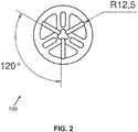
- FIGs. 2-5 show an exemplary embodiment of some dimensions of shaper 100 , which are not limited to the invention as a person skilled in the art would readily appreciate that heart valves/leaflets would vary in dimensions and shape.
- a paper by the same group as the current inventors provides guidelines for some of the dimensions. The paper is entitled “ Effects of valve geometry and tissue anisotropy on the radial stretch and coaptation area of tissue-engineered heart valves” by Loerakker et al. and published in Journal of Biomechanics 46 (2013) 1792-1800 .
- spacer 1700 is designed with three surfaces 1710 distributed/oriented with respect to each other in the same triangular pattern as how inner arms 112 are distributed.
- Side 1720 of spacer 1700 can be placed towards the top of support base 110 and will then sit at the top of the support base 100 (see also FIG. 22 ).
- Surfaces 1710 fit in the space left to fit at least the tissue growth material to separate the tissue growth materials supported by each of the linear portions 112' of the inner arms 112 . In other words, surfaces 1710 will separate the tissue growth materials.
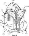
- FIGs. 6-11 show a second embodiment of a shaper 600 for maintaining and controlling heart valve geometry during culture, where shaper 600 could be viewed as an extension of shaper 100 with similar structural components.
- Shaper 600 is intended for a heart valve with three leaflets and distinguishes a support base 610 and three canopy growth surfaces 620 expanded from the second portions of their respective inner arms 112 . It is noted that only one inner arm 112 is indicated in FIG. 6 for clarity purposes.
- Each canopy growth surface 620 is capable of supporting a tissue growth material (not shown) to form one of the leaflets of the heart valve.
- the canopy growth surfaces 620 define a concave surface when moving away from the center of support base 610 in outer direction.
- the canopy growth surfaces 620 are supported by the respective first portions of the inner arms 112 and a pair of outer arms 612' , 612" defined for each of the inner arms.
- Each of the outer arms 612' , 612" have a first portion disposed normal to support base 610 and disposed distal to the center of support base 610 .
- each of the canopy growth surfaces 620 further span to the base of support surface 610 along the radial separation of the respective outer arms 612' , 612" and inner arm 112 such that each span is capable of supporting the respective growth material.
- the combinations of each of the first portions of the inner arms 112 with their respective pair of outer arms 612' , 612" define wedge-shape growth surfaces each capable of supporting the respective growth material.
- the three canopy growth surfaces 620 are distributed in a triangular pattern at support base 610 and are spaced 650 from each other forming a star design, as is evident from e.g. FIGs. 6-8 especially looking from the top down.
- the space is defined to fit at least the respective tissue growth materials.
- the tissue growth materials are placed over and against their canopy growth surfaces 620 at the medial aspects of canopy growth surfaces 620 .
- the respective tissue growth material is extended forming a wedge-shape growth material and a canopy (e.g. concave) draped over the canopy growth surfaces 620 .
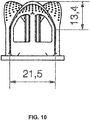
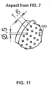
- FIGs. 7-11 show an exemplary embodiment of some dimensions of shaper 600 , which are not limited to the invention as a person skilled in the art would readily appreciate that heart valves/leaflets would vary in dimensions and shape. The same paper mentioned supra provides guidelines for some of the dimensions.
- spacer 1700 is designed with three surfaces 1710 distributed/oriented with respect to each other in the same triangular pattern as how canopy growth surfaces 620 are distributed.
- Side 1720 of spacer 1700 can be placed towards the top of support base 610 and will then sit at the top of the support base 610 (see also FIG. 22 ).
- Surfaces 1710 fit in the space left to fit at least the tissue growth material to separate the tissue growth materials supported by each of the canopy growth surfaces 620 . In other words, surfaces 1710 will separate the tissue growth materials.
- FIGs. 12-16 show a third embodiment of a shaper 1200 for maintaining and controlling heart valve geometry during culture, where shaper 1200 could be viewed as an extension of shapers 100 and 600 by having some structural components in common.
- Shaper 1200 is intended for a heart valve with three leaflets and distinguishes a support base 610 and three canopy growth surfaces 620 expanded from their respective inner arms 112. It is noted that only one inner arm 112 is indicated in FIG. 12 for clarity purposes.
- Shapers 600 and 1200 are similar with the difference that for shaper 1200 each of the canopy growth surfaces 620 further span to the base of support surface 610 with meshes surfaces 1210 between the respective outer arms 612' , 612" and inner arm 112 . Only one of the meshed surfaces is indicated for clarity purposes. It is also noted that a wedge shaped surface forms the basis for each of the concave parts of the canopy growth surfaces.
- meshes surface 1210 have holes, like holes 640 , to allow exchange of nutrients.
- Each of these canopy growth surfaces 620 is capable of supporting the respective growth material.
- spacer 1700 can be used for shaper 1200 to fit in the space 650 left to fit at least the tissue growth material to separate the tissue growth materials supported by the meshed surfaces.
- FIGs. 13-16 show an exemplary embodiment of some dimensions of shaper 1200 , which are not limited to the invention as a person skilled in the art would readily appreciate that heart valves/leaflets would vary in dimensions and shape.
- the paper is entitled " Effects of valve geometry and tissue anisotropy on the radial stretch and coaptation area of tissue-engineered heart valves" by Loerakker et al. and published in Journal of Biomechanics 46 (2013) 1792-1800 .
- FIG. 22 shows the various shapers 100 , 600 and 1200 with spacer 1700 , and tissue growth material 2200 and how they fit and can be used together.
- these embodiments can be constructed for a single-leaflet heart valve, bi-leaflet (two leaflet) heart valve) or multiple-leaflet heart valve.
- the design principles for the these different heart valves would be similar to the tri-leaflet heart valve with the difference of the number of inner arms for shaper 100 , the number of canopy growth surfaces for shaper 600 and 1200 , the shape of the space with the growth surfaces and various others as a person skilled in the art would readily appreciate.
- dimensions (including the radius/angles of the canopy growth surfaces) shown in the exemplary embodiments could be varied to fit the desired objective for the tissue engineered heart valves.
- the manufacturing of the inserts could be via conventional computer
- Circumferential collagen alignment in TEHVs will result in radial leaflet stretch while being hemodynamically loaded, which is beneficial for the opening and closing behavior of the valve.
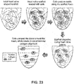
- the starter matrix of the TEHV contains mainly randomly organized scaffold fibers. When the cells are seeded onto the construct, they will start producing randomly organized collagen matrix along these scaffold fibers. During culture, the scaffold material will hydrolyze and lose mechanical functionality. From this point on cells will start pulling in the direction of constrained. Since the leaflet shaper insert is a rigid body, cells will compact around this insert and realign the collagen in the direction of constrain. This will result in circumferentially aligned collagen orientation ( FIG. 23 ).
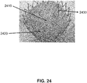
- FIGs. 24-25 show examples of in vitro results of TEHVs cultured with the use of for example shaper 1200 . After removal of shaper 1200 the TEHV maintained the imposed geometry.
- FIG. 24 shows results for a closed configuration with no leaflet retraction 2410 , maintenance of leaflet curvature 2420 and a controlled coaptation area 2430 .
- FIG. 25 shows results for an open configuration with leaflets shaped around the shaper insert 2510 , maintenance of leaflet curvature 2520 and a controlled coaptation area 2530 .
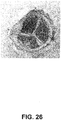
- FIG. 26 shows an example of long term in vivo results of TEHVs cultured with the use of for example shaper 1200 .
- the heart valve maintained its initial geometry and showed no signs of leaflet retraction.
Landscapes
- Health & Medical Sciences (AREA)
- Engineering & Computer Science (AREA)
- Life Sciences & Earth Sciences (AREA)
- Biomedical Technology (AREA)
- Bioinformatics & Cheminformatics (AREA)
- Organic Chemistry (AREA)
- Chemical & Material Sciences (AREA)
- Zoology (AREA)
- Wood Science & Technology (AREA)
- General Health & Medical Sciences (AREA)
- Genetics & Genomics (AREA)
- Cardiology (AREA)
- Biochemistry (AREA)
- Sustainable Development (AREA)
- General Engineering & Computer Science (AREA)
- Biotechnology (AREA)
- Microbiology (AREA)
- Transplantation (AREA)
- Animal Behavior & Ethology (AREA)
- Vascular Medicine (AREA)
- Heart & Thoracic Surgery (AREA)
- Veterinary Medicine (AREA)
- Public Health (AREA)
- Oral & Maxillofacial Surgery (AREA)
- Manufacturing & Machinery (AREA)
- Molecular Biology (AREA)
- Immunology (AREA)
- Prostheses (AREA)
- Materials For Medical Uses (AREA)
- Micro-Organisms Or Cultivation Processes Thereof (AREA)
Description
- This invention relates to devices for tissue engineering. In particular, the invention relates to devices for tissue engineering heart valves. The invention is defined by claim 1.
- Tissue engineered heart valves (TEHV) are produced by seeding cells on a heart valve shaped scaffold material, followed by a culturing period in a bioreactor system. During culture, the cells will produce an extracellular matrix (ECM).
- So far no solutions are available to control heart valve geometry during culture. Contractile cells that are being used will compact the new-formed tissue in all possible directions of constrain. Any predefined scaffold geometry at the start of culture will therefore be lost during culture, resulting in an entirely different geometry after culture compared to the imposed starter geometry.
- There are two ways of culturing the TEHV. The first method is to culture the TEHVs in a so-called "open configuration". This means that the individual heart valve leaflets are separated from each other during culture. The benefit of this approach is that the TEHV leaflets do not have to be separated after culture. The problem with this approach is that because cells will build up tension during culture, they will retract the leaflets, which results in shorted leaflets. In addition, because of the internal tension that builds up in the leaflets, the initially curved shape of the scaffold may be straightened thereby compromising the desired curvature of the leaflets and functionality of the valve.
- As an example for the "open configuration" approach,
GB 1243375 - The second method is to culture the TEHV in a "closed configuration". This means that the valve leaflets are attached to each other, which prevents shortening of the leaflets due to the internal tension that builds up in the leaflets during culture. However, it does not prevent 'straightening' or 'flattening' of the leaflets. In addition, it has been proven to be difficult to achieve a sufficiently large coaptation area between the leaflets in this way, which is crucial for in vivo functionality of the heart valve.
- The present invention addresses these problems and provides devices, which allow for the maintenance and control of heart valve geometry during culture.
- The present invention provides devices, for controlling tissue engineered heart valve leaflet geometry by using predefined inserts during tissue culture. The inserts are referred to herein as (leaflet) shapers and (leaflet) spacers, which can be used individually or in combination with each other mostly depending on the type of cells cultured with the tissue growth materials and level of geometry shaping/control.
- The first insert is a leaflet shaper and has been described herein with several different variations of embodiments. Since we observed that the cells build up tension in all constrained directions, we make use of this effect by inserting a rigid, concave construct that has the shape of the leaflet. The tension that develops in the leaflets will cause the leaflets to compact against the shaper, which acts as a constraint and is capable of controlling the curvature and coaptation of the leaflets.
- In some embodiments, the leaflet shaper is covered with small holes to achieve proper nutrient exchange between the medium and the tissue that compacts around the insert. The shaper does not cover the wall of the heart valve such that nutrients and oxygen can be supplied to the wall. Because the tissue compacts against the concave aspect of the shaper, there is no need for a second valve shaped insert/shaper on the other side of the valve leaflets.
- The second insert is a leaflet spacer and has been described herein as one embodiment that can be used in combination with the various shapers. When the leaflets are cultured in a closed configuration, the spacer will prevent retraction of the leaflets in the radial direction to constrain the height, and therefore control the size of the coaptation area. It will also enable maintenance of a predefined coaptation area. Hence, this leaflet spacer will constrain the height of the leaflets. A second advantage of the leaflet spacer is to prevent the leaflets from merging over the coaptation area during culture. Since the spacer will be positioned in between the individual leaflets, there is no chance for leaflet concrescence.
- An advantage of using the embodiments presented in this invention is that it can result in circumferential collagen orientation in the cultured heart valves, which is beneficial for heart valve functionality.
- Another advantage of using the embodiments presented in this invention is that it enables us to culture heart valves without the need of using a complex bioreactor system. In fact, the use of a simple jar would be sufficient. One of the functions of the bioreactor system was to impose the right geometry to the valves by dynamically loading them. But this inserts can achieve the same objective, which is to constrain the imposed geometry.
-
- FIG. 1
- shows according to an exemplary embodiment of the invention a three dimensional view of a
shaper 100 for maintaining and controlling the shape of tissue growth material for three leaflets of a heart valve during tissue culture. - FIG. 2
- shows according to an exemplary embodiment of the invention a top view of the shaper as shown in
FIG. 1 . The dimensions are in mm. - FIG. 3
- shows according to an exemplary embodiment of the invention a bottom view of the shaper as shown in
FIG. 1 . The dimensions are in mm. - FIGs. 4-5
- show according to an exemplary embodiment of the invention side views of the shaper as shown in
FIG. 1 . The dimensions are in mm. - FIG. 6
- shows according to an exemplary embodiment of the invention a three dimensional view of a
shaper 600 for maintaining and controlling the shape of tissue growth material for three leaflets of a heart valve during tissue culture. - FIG. 7
- shows according to an exemplary embodiment of the invention a top view of the shaper as shown in
FIG. 6 . The dimensions are in mm. - FIG. 8
- shows according to an exemplary embodiment of the invention a bottom view of the shaper as shown in
FIG. 6 . The dimensions are in mm. - FIGs. 9-10
- show according to an exemplary embodiment of the invention side views of the shaper as shown in
FIG. 6 . The dimensions are in mm. - FIG. 11
- shows according to an exemplary embodiment of the invention a detailed aspect of a meshed surface area with holes from
FIG. 7 . The dimensions are in mm. - FIG. 12
- shows according to an exemplary embodiment of the invention a three dimensional view of a
shaper 1200 for maintaining and controlling the shape of tissue growth material for three leaflets of a heart valve during tissue culture. - FIG. 13
- shows according to an exemplary embodiment of the invention a top view of the shaper as shown in
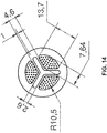
FIG. 12 . The dimensions are in mm. - FIG. 14
- shows according to an exemplary embodiment of the invention a bottom view of the shaper as shown in
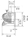
FIG. 12 . The dimensions are in mm. - FIGs. 15-16
- show according to an exemplary embodiment of the invention side views of the shaper as shown in
FIG. 12 . The dimensions are in mm. - FIG. 17
- shows according to an exemplary embodiment of the invention a three dimensional view of a
spacer 1700 for further maintaining and controlling the shape of tissue growth material for three leaflets of a heart valve during tissue culture. - FIGs. 18-19
- show according to an exemplary embodiment of the invention top views of the spacer as shown in
FIG. 17 . The dimensions are in mm. - FIGs. 20-21
- show according to an exemplary embodiment of the invention side views of the spacer as shown in
FIG. 17 . The dimensions are in mm. - FIG. 22
- shows according to an exemplary embodiment of the invention the
various shapers spacer 1700, andtissue growth material 2200 and how they fit and can be used together. - FIG. 23
- shows according to an exemplary embodiment of the invention a change from random collagen orientation towards circumferential aligned collagen orientation, due to the leaflet shaper insert during culture.
- FIGs. 24-25
- show according to exemplary embodiments of the invention in vitro results of TEHVs cultured with the use of, for example, but not limited to
shaper 1200. - FIG. 26
- shows according to an exemplary embodiment of the invention long term in vivo results of TEHVs cultured with the use of, for example, but not limited to
shaper 1200. -
FIGs. 1-5 show a first embodiment of ashaper 100 for maintaining and controlling heart valve geometry during culture.Shaper 100 is intended for a heart valve with three leaflets and distinguishes asupport base 110 and threeinner arms 112 each capable of supporting a tissue growth material (not shown) to form one of the leaflets of the heart valve. In this embodiment, it is the mid-axis of the heart valve leaflets that will be constrained and controlled during culture. - Each of the
inner arms 112 has a first portion 112' and asecond portion 112", which is only indicated for one of the inner arms for clarity purposes. First portion 112' is disposed normal to supportbase 110 and disposed proximal to a center ofsupport base 110.Second portion 112" is nonlinear and disposed distal to supportbase 110 and bends away from the center ofsupport base 110. - The
inner arms 112 are distributed in a triangular pattern atsupport base 110 and are spaced from each other, as is evident inFIG. 1 , to define enough space to fit at least the respective tissue growth materials. In other words, the tissue growth materials are placed over and against their respectiveinner arms 112 at themedial aspects 114 of inner arms 112 (114 is only indicated for one of theinner arms 112 for clarity purposes). In this embodiment, the respective tissue growth material is extended (not shown) toarea 116' and 116" forming a wedge-shape growth material and a canopy (e.g. concave) draped oversecond portion 112". -
FIGs. 2-5 show an exemplary embodiment of some dimensions ofshaper 100, which are not limited to the invention as a person skilled in the art would readily appreciate that heart valves/leaflets would vary in dimensions and shape. A paper by the same group as the current inventors provides guidelines for some of the dimensions. The paper is entitled "Effects of valve geometry and tissue anisotropy on the radial stretch and coaptation area of tissue-engineered heart valves" by Loerakker et al. and published in Journal of Biomechanics 46 (2013) 1792-1800. - Depending on the type of cells used with the tissue growth material for
shaper 100, there might be a desire to further control the shape and/or spacing between the tissue growth materials draped against theinner arms 112. For this purpose,spacer 1700 is designed with threesurfaces 1710 distributed/oriented with respect to each other in the same triangular pattern as howinner arms 112 are distributed.Side 1720 ofspacer 1700 can be placed towards the top ofsupport base 110 and will then sit at the top of the support base 100 (see alsoFIG. 22 ).Surfaces 1710 fit in the space left to fit at least the tissue growth material to separate the tissue growth materials supported by each of the linear portions 112' of theinner arms 112. In other words,surfaces 1710 will separate the tissue growth materials. -
FIGs. 6-11 show a second embodiment of ashaper 600 for maintaining and controlling heart valve geometry during culture, whereshaper 600 could be viewed as an extension ofshaper 100 with similar structural components.Shaper 600 is intended for a heart valve with three leaflets and distinguishes asupport base 610 and three canopy growth surfaces 620 expanded from the second portions of their respectiveinner arms 112. It is noted that only oneinner arm 112 is indicated inFIG. 6 for clarity purposes. - Each
canopy growth surface 620 is capable of supporting a tissue growth material (not shown) to form one of the leaflets of the heart valve. The canopy growth surfaces 620 define a concave surface when moving away from the center ofsupport base 610 in outer direction. - The canopy growth surfaces 620 are supported by the respective first portions of the
inner arms 112 and a pair ofouter arms 612', 612" defined for each of the inner arms. Each of theouter arms 612', 612" have a first portion disposed normal to supportbase 610 and disposed distal to the center ofsupport base 610. - In other words, each of the canopy growth surfaces 620 further span to the base of
support surface 610 along the radial separation of the respectiveouter arms 612', 612" andinner arm 112 such that each span is capable of supporting the respective growth material. Differently stated, the combinations of each of the first portions of theinner arms 112 with their respective pair ofouter arms 612', 612" define wedge-shape growth surfaces each capable of supporting the respective growth material. As a result the tissue growth material for the heart valve leaflets will be constraint and controlled during culture. Open area 630 (indicated for only one of the leaflet canopy growth surfaces for clarity purposes) is left open as it could enhance tissue formation.Holes 640 are intended to allow improved exchange of nutrients. - The three canopy growth surfaces 620 are distributed in a triangular pattern at
support base 610 and are spaced 650 from each other forming a star design, as is evident from e.g.FIGs. 6-8 especially looking from the top down. The space is defined to fit at least the respective tissue growth materials. In other words, the tissue growth materials are placed over and against their canopy growth surfaces 620 at the medial aspects of canopy growth surfaces 620. In this embodiment, the respective tissue growth material is extended forming a wedge-shape growth material and a canopy (e.g. concave) draped over the canopy growth surfaces 620. -
FIGs. 7-11 show an exemplary embodiment of some dimensions ofshaper 600, which are not limited to the invention as a person skilled in the art would readily appreciate that heart valves/leaflets would vary in dimensions and shape. The same paper mentioned supra provides guidelines for some of the dimensions. - Depending on the type of cells used with the tissue growth material for
shaper 600, there might be a desire to further control the shape and/or spacing between the tissue growth materials draped against the canopy growth surfaces 620. For this purpose,spacer 1700 is designed with threesurfaces 1710 distributed/oriented with respect to each other in the same triangular pattern as how canopy growth surfaces 620 are distributed.Side 1720 ofspacer 1700 can be placed towards the top ofsupport base 610 and will then sit at the top of the support base 610 (see alsoFIG. 22 ).Surfaces 1710 fit in the space left to fit at least the tissue growth material to separate the tissue growth materials supported by each of the canopy growth surfaces 620. In other words,surfaces 1710 will separate the tissue growth materials. -
FIGs. 12-16 show a third embodiment of ashaper 1200 for maintaining and controlling heart valve geometry during culture, whereshaper 1200 could be viewed as an extension ofshapers Shaper 1200 is intended for a heart valve with three leaflets and distinguishes asupport base 610 and three canopy growth surfaces 620 expanded from their respectiveinner arms 112. It is noted that only oneinner arm 112 is indicated inFIG. 12 for clarity purposes. -
Shapers shaper 1200 each of the canopy growth surfaces 620 further span to the base ofsupport surface 610 withmeshes surfaces 1210 between the respectiveouter arms 612', 612" andinner arm 112. Only one of the meshed surfaces is indicated for clarity purposes. It is also noted that a wedge shaped surface forms the basis for each of the concave parts of the canopy growth surfaces. - Another difference is that the meshes surface 1210 have holes, like
holes 640, to allow exchange of nutrients. Each of these canopy growth surfaces 620 is capable of supporting the respective growth material. Similar to shaper 600, spacer 1700 can be used forshaper 1200 to fit in thespace 650 left to fit at least the tissue growth material to separate the tissue growth materials supported by the meshed surfaces. -
FIGs. 13-16 show an exemplary embodiment of some dimensions ofshaper 1200, which are not limited to the invention as a person skilled in the art would readily appreciate that heart valves/leaflets would vary in dimensions and shape. The paper is entitled "Effects of valve geometry and tissue anisotropy on the radial stretch and coaptation area of tissue-engineered heart valves" by Loerakker et al. and published in Journal of Biomechanics 46 (2013) 1792-1800. - In summary,
FIG. 22 shows thevarious shapers spacer 1700, andtissue growth material 2200 and how they fit and can be used together. There are various variations one could imagine, such as that these embodiments can be constructed for a single-leaflet heart valve, bi-leaflet (two leaflet) heart valve) or multiple-leaflet heart valve. The design principles for the these different heart valves would be similar to the tri-leaflet heart valve with the difference of the number of inner arms forshaper 100, the number of canopy growth surfaces forshaper - The manufacturing of the inserts could be via conventional computer
- Circumferential collagen alignment in TEHVs will result in radial leaflet stretch while being hemodynamically loaded, which is beneficial for the opening and closing behavior of the valve. As shown in
FIG. 23 , the starter matrix of the TEHV contains mainly randomly organized scaffold fibers. When the cells are seeded onto the construct, they will start producing randomly organized collagen matrix along these scaffold fibers. During culture, the scaffold material will hydrolyze and lose mechanical functionality. From this point on cells will start pulling in the direction of constrained. Since the leaflet shaper insert is a rigid body, cells will compact around this insert and realign the collagen in the direction of constrain. This will result in circumferentially aligned collagen orientation (FIG. 23 ). - Currently TEHVs are being cultured in a sophisticated bioreactor system. This system is regulating pulsatile pressures onto the leaflets in combination with regulated medium flow to enhance tissue formation. We found out that by using the insert as presented herein during culture, the bioreactor system can be replaced by a simple jar. Since the insert is required to maintain the initial heart valve geometry, it is hampering the pulsatile pressures exerted on the leaflets, which makes the main function of the bioreactor system redundant or obsolete. It seems that when the fluid flow is maintained, it would still be possible to culture functional TEHVs. This finding can have a big impact in the way TEHVs can be produced in a future commercial way. Without the use of a complicated bioreactor system, valve production can be up scaled easily and will lower the production costs.
-
FIGs. 24-25 show examples of in vitro results of TEHVs cultured with the use of forexample shaper 1200. After removal ofshaper 1200 the TEHV maintained the imposed geometry.FIG. 24 shows results for a closed configuration with noleaflet retraction 2410, maintenance ofleaflet curvature 2420 and a controlledcoaptation area 2430.FIG. 25 shows results for an open configuration with leaflets shaped around theshaper insert 2510, maintenance ofleaflet curvature 2520 and a controlledcoaptation area 2530. -
FIG. 26 shows an example of long term in vivo results of TEHVs cultured with the use of forexample shaper 1200. Up to 24 weeks, the heart valve maintained its initial geometry and showed no signs of leaflet retraction. These results confirm that the initial geometry of the heart valve after culture is decisive for the final long-term outcome, which can only be obtained by using the leaflet shaper insert during culture.
Claims (9)
- A heart valve cell culturing device, wherein the heart valve comprises at least two leaflets, the device comprising:(a) a support base (110); and(b) at least two inner arms (112) each capable of supporting a tissue growth material to form one of the leaflets,wherein each of the inner arms (112) has a first portion (112') and a second portion (112"),
wherein the first portion (112') is disposed normal to the support base (110) and disposed proximal to a center of the support base,
wherein the second portion (112") is nonlinear and disposed distal to the support base and bends away from the center of the support base, wherein the at least two inner arms (112) are distributed in a pattern at the support base, and
wherein the at least two inner arms (112) are spaced from each other defining enough space to fit at least the respective tissue growth materials;
the device further comprising a spacer (1700) to fit in said space and to separate the tissue growth materials supported by each of the linear portions (112') of the inner arms (112);
characterized in that
the spacer (1700) comprises at least two planar surfaces (1710), all of the planar surfaces having a common intersection line, the intersection line being substantially parallel to and circumferentially surrounded by said linear portions (112') of the inner arms (112). - The heart valve cell culturing device as set forth in claim 1, wherein each of the inner arms further comprises a canopy growth surface (620) expanded from the second portion of the respective inner arms, wherein each of the canopy growth surfaces define a concave surface when moving away from the center of the support base (610) in outer direction, wherein each of the canopy growth surfaces is supported by the first portions (112') of the inner arms (112) and a pair of outer arms (612', 612") defined for each of the inner arms, wherein each of the outer arms have a first portion disposed normal to the support base and disposed distal to the center of the support base, and wherein each of the canopy growth surfaces are capable of supporting the respective growth materials.
- The heart valve cell culturing device as set forth in claim 2, wherein the canopy growth surfaces (620) comprise holes (640) to allow exchange of nutrients.
- The heart valve cell culturing device as set forth in claim 2, wherein each of the canopy growth surfaces (620) further span to the base of the support surface (610) along the radial separation of the respective outer arms (612', 612") and inner arm (112), wherein each span capable of supporting the respective growth material.
- The heart valve cell culturing device as set forth in claim 2, wherein each of the canopy growth surfaces (620) further span to the base of the support surface and form meshes surfaces (1210) between the respective outer arms (612', 612") and inner arm (112) each capable of supporting the respective growth material.
- The heart valve cell culturing device as set forth in claim 5, wherein the meshes surfaces (1210) comprise holes (640) to allow exchange of nutrients.
- The heart valve cell culturing device as set forth in claim 2, wherein the combinations of each of the first portions (112') of the inner arms (112) with their respective pair of outer arms (612', 612") define wedge-shape growth surfaces each capable of supporting the respective growth material.
- The heart valve cell culturing device as set forth in claim 7, wherein the wedge-shape growth surfaces comprise holes (640) to allow exchange of nutrients.
- The heart valve cell culturing device as set forth in claim 1, wherein the at least two inner arms have three inner arms (112) and the pattern is a triangular pattern.
Applications Claiming Priority (2)
| Application Number | Priority Date | Filing Date | Title |
|---|---|---|---|
| US201361883870P | 2013-09-27 | 2013-09-27 | |
| PCT/EP2014/070352 WO2015044190A1 (en) | 2013-09-27 | 2014-09-24 | Controlling tissue engineered heart valve geometry by using predefined inserts during culture |
Publications (2)
| Publication Number | Publication Date |
|---|---|
| EP3049025A1 EP3049025A1 (en) | 2016-08-03 |
| EP3049025B1 true EP3049025B1 (en) | 2018-01-10 |
Family
ID=51619172
Family Applications (1)
| Application Number | Title | Priority Date | Filing Date |
|---|---|---|---|
| EP14772332.4A Active EP3049025B1 (en) | 2013-09-27 | 2014-09-24 | Controlling tissue engineered heart valve geometry by using predefined inserts during culture |
Country Status (4)
| Country | Link |
|---|---|
| US (1) | US10213297B2 (en) |
| EP (1) | EP3049025B1 (en) |
| JP (1) | JP6505674B2 (en) |
| WO (1) | WO2015044190A1 (en) |
Cited By (15)
| Publication number | Priority date | Publication date | Assignee | Title |
|---|---|---|---|---|
| US10856984B2 (en) | 2017-08-25 | 2020-12-08 | Neovasc Tiara Inc. | Sequentially deployed transcatheter mitral valve prosthesis |
| US10940001B2 (en) | 2012-05-30 | 2021-03-09 | Neovasc Tiara Inc. | Methods and apparatus for loading a prosthesis onto a delivery system |
| US11311376B2 (en) | 2019-06-20 | 2022-04-26 | Neovase Tiara Inc. | Low profile prosthetic mitral valve |
| US11357622B2 (en) | 2016-01-29 | 2022-06-14 | Neovase Tiara Inc. | Prosthetic valve for avoiding obstruction of outflow |
| US11389291B2 (en) | 2013-04-04 | 2022-07-19 | Neovase Tiara Inc. | Methods and apparatus for delivering a prosthetic valve to a beating heart |
| US11413139B2 (en) | 2011-11-23 | 2022-08-16 | Neovasc Tiara Inc. | Sequentially deployed transcatheter mitral valve prosthesis |
| US11419720B2 (en) | 2010-05-05 | 2022-08-23 | Neovasc Tiara Inc. | Transcatheter mitral valve prosthesis |
| US11464631B2 (en) | 2016-11-21 | 2022-10-11 | Neovasc Tiara Inc. | Methods and systems for rapid retraction of a transcatheter heart valve delivery system |
| US11491006B2 (en) | 2019-04-10 | 2022-11-08 | Neovasc Tiara Inc. | Prosthetic valve with natural blood flow |
| US11497602B2 (en) | 2012-02-14 | 2022-11-15 | Neovasc Tiara Inc. | Methods and apparatus for engaging a valve prosthesis with tissue |
| US11602429B2 (en) | 2019-04-01 | 2023-03-14 | Neovasc Tiara Inc. | Controllably deployable prosthetic valve |
| US11737872B2 (en) | 2018-11-08 | 2023-08-29 | Neovasc Tiara Inc. | Ventricular deployment of a transcatheter mitral valve prosthesis |
| US11779742B2 (en) | 2019-05-20 | 2023-10-10 | Neovasc Tiara Inc. | Introducer with hemostasis mechanism |
| US11998447B2 (en) | 2019-03-08 | 2024-06-04 | Neovasc Tiara Inc. | Retrievable prosthesis delivery system |
| US12109111B2 (en) | 2015-12-15 | 2024-10-08 | Neovasc Tiara Inc. | Transseptal delivery system |
Families Citing this family (4)
| Publication number | Priority date | Publication date | Assignee | Title |
|---|---|---|---|---|
| US9968447B2 (en) * | 2016-01-22 | 2018-05-15 | Medtronic Vascular, Inc. | Bioprosthetic tissue for use as a prosthetic valve leaflet and method of preparing |
| JP7689736B2 (en) | 2019-01-14 | 2025-06-09 | プレジデント アンド フェローズ オブ ハーバード カレッジ | Focused Rotary Jet Spinning Devices and Methods of Their Use - Patent application |
| EP3956500A1 (en) * | 2019-08-02 | 2022-02-23 | Edwards Lifesciences Corporation | Rotary application of fibrous material to medical devices |
| GB2624469A (en) * | 2022-11-21 | 2024-05-22 | Univ Nottingham Trent | Insert |
Family Cites Families (5)
| Publication number | Priority date | Publication date | Assignee | Title |
|---|---|---|---|---|
| US3514791A (en) * | 1967-07-25 | 1970-06-02 | Charles H Sparks | Tissue grafts |
| DE10235237A1 (en) * | 2002-08-01 | 2004-02-12 | Symetis Ag | In vitro preparation of homologous heart valves, useful for replacement of diseased valves, by inoculating biodegradable carrier with fibroblasts and attachment to a non-degradable stent |
| NL1026076C2 (en) | 2004-04-29 | 2005-11-01 | Univ Eindhoven Tech | Molded part manufactured by means of electro-spinning and a method for the manufacture thereof as well as the use of such a molded part. |
| EP2431061A3 (en) | 2006-06-09 | 2012-08-08 | Eidgenössische Technische Hochschule Zürich | Valve model for producing scaffolds for artificial heart valves and vascular structures |
| US8900862B2 (en) * | 2011-03-23 | 2014-12-02 | The Regents Of The University Of California | Mesh enclosed tissue constructs |
-
2014
- 2014-09-24 WO PCT/EP2014/070352 patent/WO2015044190A1/en not_active Ceased
- 2014-09-24 US US15/024,857 patent/US10213297B2/en active Active
- 2014-09-24 JP JP2016518169A patent/JP6505674B2/en active Active
- 2014-09-24 EP EP14772332.4A patent/EP3049025B1/en active Active
Cited By (25)
| Publication number | Priority date | Publication date | Assignee | Title |
|---|---|---|---|---|
| US12611303B2 (en) | 2010-05-05 | 2026-04-28 | Neovasc Tiara Inc. | Transcatheter mitral valve prosthesis |
| US11419720B2 (en) | 2010-05-05 | 2022-08-23 | Neovasc Tiara Inc. | Transcatheter mitral valve prosthesis |
| US11413139B2 (en) | 2011-11-23 | 2022-08-16 | Neovasc Tiara Inc. | Sequentially deployed transcatheter mitral valve prosthesis |
| US12053369B2 (en) | 2011-11-23 | 2024-08-06 | Neovasc Tiara Inc. | Sequentially deployed transcatheter mitral valve prosthesis |
| US12138159B2 (en) | 2012-02-14 | 2024-11-12 | Neovasc Tiara Inc. | Methods and apparatus for engaging a valve prosthesis with tissue |
| US11497602B2 (en) | 2012-02-14 | 2022-11-15 | Neovasc Tiara Inc. | Methods and apparatus for engaging a valve prosthesis with tissue |
| US11617650B2 (en) | 2012-05-30 | 2023-04-04 | Neovasc Tiara Inc. | Methods and apparatus for loading a prosthesis onto a delivery system |
| US10940001B2 (en) | 2012-05-30 | 2021-03-09 | Neovasc Tiara Inc. | Methods and apparatus for loading a prosthesis onto a delivery system |
| US11389294B2 (en) | 2012-05-30 | 2022-07-19 | Neovasc Tiara Inc. | Methods and apparatus for loading a prosthesis onto a delivery system |
| US11389291B2 (en) | 2013-04-04 | 2022-07-19 | Neovase Tiara Inc. | Methods and apparatus for delivering a prosthetic valve to a beating heart |
| US12109111B2 (en) | 2015-12-15 | 2024-10-08 | Neovasc Tiara Inc. | Transseptal delivery system |
| US12193932B2 (en) | 2016-01-29 | 2025-01-14 | Neovasc Tiara Inc. | Prosthetic valve for avoiding obstruction of outflow |
| US11357622B2 (en) | 2016-01-29 | 2022-06-14 | Neovase Tiara Inc. | Prosthetic valve for avoiding obstruction of outflow |
| US11464631B2 (en) | 2016-11-21 | 2022-10-11 | Neovasc Tiara Inc. | Methods and systems for rapid retraction of a transcatheter heart valve delivery system |
| US12201524B2 (en) | 2016-11-21 | 2025-01-21 | Neovasc Tiara Inc. | Methods and systems for rapid retraction of a transcatheter heart valve delivery system |
| US11793640B2 (en) | 2017-08-25 | 2023-10-24 | Neovasc Tiara Inc. | Sequentially deployed transcatheter mitral valve prosthesis |
| US10856984B2 (en) | 2017-08-25 | 2020-12-08 | Neovasc Tiara Inc. | Sequentially deployed transcatheter mitral valve prosthesis |
| US11737872B2 (en) | 2018-11-08 | 2023-08-29 | Neovasc Tiara Inc. | Ventricular deployment of a transcatheter mitral valve prosthesis |
| US11998447B2 (en) | 2019-03-08 | 2024-06-04 | Neovasc Tiara Inc. | Retrievable prosthesis delivery system |
| US11602429B2 (en) | 2019-04-01 | 2023-03-14 | Neovasc Tiara Inc. | Controllably deployable prosthetic valve |
| US12036117B2 (en) | 2019-04-10 | 2024-07-16 | Neovasc Tiara Inc. | Prosthetic valve with natural blood flow |
| US11491006B2 (en) | 2019-04-10 | 2022-11-08 | Neovasc Tiara Inc. | Prosthetic valve with natural blood flow |
| US11779742B2 (en) | 2019-05-20 | 2023-10-10 | Neovasc Tiara Inc. | Introducer with hemostasis mechanism |
| US11931254B2 (en) | 2019-06-20 | 2024-03-19 | Neovasc Tiara Inc. | Low profile prosthetic mitral valve |
| US11311376B2 (en) | 2019-06-20 | 2022-04-26 | Neovase Tiara Inc. | Low profile prosthetic mitral valve |
Also Published As
| Publication number | Publication date |
|---|---|
| WO2015044190A1 (en) | 2015-04-02 |
| US20160235527A1 (en) | 2016-08-18 |
| US10213297B2 (en) | 2019-02-26 |
| JP6505674B2 (en) | 2019-04-24 |
| JP2016531627A (en) | 2016-10-13 |
| EP3049025A1 (en) | 2016-08-03 |
Similar Documents
| Publication | Publication Date | Title |
|---|---|---|
| US10213297B2 (en) | Controlling tissue engineered heart valve geometry by using predefined inserts during culture | |
| EP4115853B1 (en) | Implantable vein frame | |
| Fullilove et al. | Nuclear elongation and cytokinesis in Drosophila montana | |
| Höhn et al. | Dynamics of a Volvox embryo turning itself inside out | |
| Audette et al. | The molecular mechanisms underlying lens fiber elongation | |
| US20110004304A1 (en) | Culturing retinal cells and tissues | |
| NZ602707A (en) | Methods of conditioning sheet bioprosthetic tissue | |
| CN102088929A (en) | Intraocular lens and its manufacturing method | |
| WO2013019756A3 (en) | Artificial valved conduits for cardiac reconstructive procedures and methods for their production | |
| JP2007530230A5 (en) | ||
| CN112891028A (en) | Replacement heart valve and methods of use and manufacture thereof | |
| EP3181097B1 (en) | Low-modulus medical implantation porous support structure | |
| US20140243995A1 (en) | Stacked planar sheet tissue engineering scaffolds with 3d structural order | |
| CN101680011A (en) | Method for preparing structures comprising crystalline cellulose | |
| Ferro Desideri et al. | Iris reconstruction: A surgeon’s guide | |
| US20080166796A1 (en) | Device for Cell Culture on Deformable Surfaces | |
| EP2167641B1 (en) | Method and device for forming a three-dimensional arrangement of biological cells | |
| CN114080199B (en) | Electrospun heart valves | |
| CN103491907A (en) | Intraocular lens implantation tool | |
| US11767613B2 (en) | Medical implant preform produced using an inside out flipping method | |
| Voldřich | Experimental and topographic morphology in cochlear mechanics | |
| WO2024135687A1 (en) | Artificial tissue tube and method for producing same | |
| Fleury | Dynamic topology of the cephalochordate to amniote morphological transition: A self-organized system of Russian dolls | |
| Nath et al. | Intestinal and optic-cup organoids as tools for unveiling mechanics of self-organizing morphogenesis | |
| JP2010082290A (en) | Multifocal intraocular lens and method of manufacturing the same |
Legal Events
| Date | Code | Title | Description |
|---|---|---|---|
| PUAI | Public reference made under article 153(3) epc to a published international application that has entered the european phase |
Free format text: ORIGINAL CODE: 0009012 |
|
| 17P | Request for examination filed |
Effective date: 20160331 |
|
| AK | Designated contracting states |
Kind code of ref document: A1 Designated state(s): AL AT BE BG CH CY CZ DE DK EE ES FI FR GB GR HR HU IE IS IT LI LT LU LV MC MK MT NL NO PL PT RO RS SE SI SK SM TR |
|
| AX | Request for extension of the european patent |
Extension state: BA ME |
|
| DAX | Request for extension of the european patent (deleted) | ||
| GRAP | Despatch of communication of intention to grant a patent |
Free format text: ORIGINAL CODE: EPIDOSNIGR1 |
|
| INTG | Intention to grant announced |
Effective date: 20170821 |
|
| GRAS | Grant fee paid |
Free format text: ORIGINAL CODE: EPIDOSNIGR3 |
|
| GRAA | (expected) grant |
Free format text: ORIGINAL CODE: 0009210 |
|
| AK | Designated contracting states |
Kind code of ref document: B1 Designated state(s): AL AT BE BG CH CY CZ DE DK EE ES FI FR GB GR HR HU IE IS IT LI LT LU LV MC MK MT NL NO PL PT RO RS SE SI SK SM TR |
|
| REG | Reference to a national code |
Ref country code: CH Ref legal event code: EP Ref country code: AT Ref legal event code: REF Ref document number: 961579 Country of ref document: AT Kind code of ref document: T Effective date: 20180115 |
|
| REG | Reference to a national code |
Ref country code: IE Ref legal event code: FG4D |
|
| REG | Reference to a national code |
Ref country code: DE Ref legal event code: R096 Ref document number: 602014019692 Country of ref document: DE Ref country code: CH Ref legal event code: NV Representative=s name: SCHMAUDER AND PARTNER AG PATENT- UND MARKENANW, CH |
|
| REG | Reference to a national code |
Ref country code: NL Ref legal event code: FP |
|
| REG | Reference to a national code |
Ref country code: AT Ref legal event code: MK05 Ref document number: 961579 Country of ref document: AT Kind code of ref document: T Effective date: 20180110 |
|
| PG25 | Lapsed in a contracting state [announced via postgrant information from national office to epo] |
Ref country code: ES Free format text: LAPSE BECAUSE OF FAILURE TO SUBMIT A TRANSLATION OF THE DESCRIPTION OR TO PAY THE FEE WITHIN THE PRESCRIBED TIME-LIMIT Effective date: 20180110 Ref country code: CY Free format text: LAPSE BECAUSE OF FAILURE TO SUBMIT A TRANSLATION OF THE DESCRIPTION OR TO PAY THE FEE WITHIN THE PRESCRIBED TIME-LIMIT Effective date: 20180110 Ref country code: FI Free format text: LAPSE BECAUSE OF FAILURE TO SUBMIT A TRANSLATION OF THE DESCRIPTION OR TO PAY THE FEE WITHIN THE PRESCRIBED TIME-LIMIT Effective date: 20180110 Ref country code: LT Free format text: LAPSE BECAUSE OF FAILURE TO SUBMIT A TRANSLATION OF THE DESCRIPTION OR TO PAY THE FEE WITHIN THE PRESCRIBED TIME-LIMIT Effective date: 20180110 Ref country code: HR Free format text: LAPSE BECAUSE OF FAILURE TO SUBMIT A TRANSLATION OF THE DESCRIPTION OR TO PAY THE FEE WITHIN THE PRESCRIBED TIME-LIMIT Effective date: 20180110 Ref country code: NO Free format text: LAPSE BECAUSE OF FAILURE TO SUBMIT A TRANSLATION OF THE DESCRIPTION OR TO PAY THE FEE WITHIN THE PRESCRIBED TIME-LIMIT Effective date: 20180410 |
|
| PG25 | Lapsed in a contracting state [announced via postgrant information from national office to epo] |
Ref country code: AT Free format text: LAPSE BECAUSE OF FAILURE TO SUBMIT A TRANSLATION OF THE DESCRIPTION OR TO PAY THE FEE WITHIN THE PRESCRIBED TIME-LIMIT Effective date: 20180110 Ref country code: PL Free format text: LAPSE BECAUSE OF FAILURE TO SUBMIT A TRANSLATION OF THE DESCRIPTION OR TO PAY THE FEE WITHIN THE PRESCRIBED TIME-LIMIT Effective date: 20180110 Ref country code: BG Free format text: LAPSE BECAUSE OF FAILURE TO SUBMIT A TRANSLATION OF THE DESCRIPTION OR TO PAY THE FEE WITHIN THE PRESCRIBED TIME-LIMIT Effective date: 20180410 Ref country code: RS Free format text: LAPSE BECAUSE OF FAILURE TO SUBMIT A TRANSLATION OF THE DESCRIPTION OR TO PAY THE FEE WITHIN THE PRESCRIBED TIME-LIMIT Effective date: 20180110 Ref country code: LV Free format text: LAPSE BECAUSE OF FAILURE TO SUBMIT A TRANSLATION OF THE DESCRIPTION OR TO PAY THE FEE WITHIN THE PRESCRIBED TIME-LIMIT Effective date: 20180110 Ref country code: SE Free format text: LAPSE BECAUSE OF FAILURE TO SUBMIT A TRANSLATION OF THE DESCRIPTION OR TO PAY THE FEE WITHIN THE PRESCRIBED TIME-LIMIT Effective date: 20180110 Ref country code: GR Free format text: LAPSE BECAUSE OF FAILURE TO SUBMIT A TRANSLATION OF THE DESCRIPTION OR TO PAY THE FEE WITHIN THE PRESCRIBED TIME-LIMIT Effective date: 20180411 Ref country code: IS Free format text: LAPSE BECAUSE OF FAILURE TO SUBMIT A TRANSLATION OF THE DESCRIPTION OR TO PAY THE FEE WITHIN THE PRESCRIBED TIME-LIMIT Effective date: 20180510 |
|
| REG | Reference to a national code |
Ref country code: FR Ref legal event code: PLFP Year of fee payment: 5 |
|
| REG | Reference to a national code |
Ref country code: DE Ref legal event code: R097 Ref document number: 602014019692 Country of ref document: DE |
|
| PG25 | Lapsed in a contracting state [announced via postgrant information from national office to epo] |
Ref country code: RO Free format text: LAPSE BECAUSE OF FAILURE TO SUBMIT A TRANSLATION OF THE DESCRIPTION OR TO PAY THE FEE WITHIN THE PRESCRIBED TIME-LIMIT Effective date: 20180110 Ref country code: AL Free format text: LAPSE BECAUSE OF FAILURE TO SUBMIT A TRANSLATION OF THE DESCRIPTION OR TO PAY THE FEE WITHIN THE PRESCRIBED TIME-LIMIT Effective date: 20180110 Ref country code: EE Free format text: LAPSE BECAUSE OF FAILURE TO SUBMIT A TRANSLATION OF THE DESCRIPTION OR TO PAY THE FEE WITHIN THE PRESCRIBED TIME-LIMIT Effective date: 20180110 |
|
| PLBE | No opposition filed within time limit |
Free format text: ORIGINAL CODE: 0009261 |
|
| STAA | Information on the status of an ep patent application or granted ep patent |
Free format text: STATUS: NO OPPOSITION FILED WITHIN TIME LIMIT |
|
| PG25 | Lapsed in a contracting state [announced via postgrant information from national office to epo] |
Ref country code: DK Free format text: LAPSE BECAUSE OF FAILURE TO SUBMIT A TRANSLATION OF THE DESCRIPTION OR TO PAY THE FEE WITHIN THE PRESCRIBED TIME-LIMIT Effective date: 20180110 Ref country code: SM Free format text: LAPSE BECAUSE OF FAILURE TO SUBMIT A TRANSLATION OF THE DESCRIPTION OR TO PAY THE FEE WITHIN THE PRESCRIBED TIME-LIMIT Effective date: 20180110 Ref country code: CZ Free format text: LAPSE BECAUSE OF FAILURE TO SUBMIT A TRANSLATION OF THE DESCRIPTION OR TO PAY THE FEE WITHIN THE PRESCRIBED TIME-LIMIT Effective date: 20180110 Ref country code: SK Free format text: LAPSE BECAUSE OF FAILURE TO SUBMIT A TRANSLATION OF THE DESCRIPTION OR TO PAY THE FEE WITHIN THE PRESCRIBED TIME-LIMIT Effective date: 20180110 |
|
| 26N | No opposition filed |
Effective date: 20181011 |
|
| PG25 | Lapsed in a contracting state [announced via postgrant information from national office to epo] |
Ref country code: SI Free format text: LAPSE BECAUSE OF FAILURE TO SUBMIT A TRANSLATION OF THE DESCRIPTION OR TO PAY THE FEE WITHIN THE PRESCRIBED TIME-LIMIT Effective date: 20180110 |
|
| PG25 | Lapsed in a contracting state [announced via postgrant information from national office to epo] |
Ref country code: MC Free format text: LAPSE BECAUSE OF FAILURE TO SUBMIT A TRANSLATION OF THE DESCRIPTION OR TO PAY THE FEE WITHIN THE PRESCRIBED TIME-LIMIT Effective date: 20180110 |
|
| REG | Reference to a national code |
Ref country code: BE Ref legal event code: MM Effective date: 20180930 |
|
| REG | Reference to a national code |
Ref country code: IE Ref legal event code: MM4A |
|
| PG25 | Lapsed in a contracting state [announced via postgrant information from national office to epo] |
Ref country code: LU Free format text: LAPSE BECAUSE OF NON-PAYMENT OF DUE FEES Effective date: 20180924 |
|
| PG25 | Lapsed in a contracting state [announced via postgrant information from national office to epo] |
Ref country code: IE Free format text: LAPSE BECAUSE OF NON-PAYMENT OF DUE FEES Effective date: 20180924 |
|
| PG25 | Lapsed in a contracting state [announced via postgrant information from national office to epo] |
Ref country code: BE Free format text: LAPSE BECAUSE OF NON-PAYMENT OF DUE FEES Effective date: 20180930 |
|
| PG25 | Lapsed in a contracting state [announced via postgrant information from national office to epo] |
Ref country code: MT Free format text: LAPSE BECAUSE OF NON-PAYMENT OF DUE FEES Effective date: 20180924 |
|
| PG25 | Lapsed in a contracting state [announced via postgrant information from national office to epo] |
Ref country code: TR Free format text: LAPSE BECAUSE OF FAILURE TO SUBMIT A TRANSLATION OF THE DESCRIPTION OR TO PAY THE FEE WITHIN THE PRESCRIBED TIME-LIMIT Effective date: 20180110 |
|
| PG25 | Lapsed in a contracting state [announced via postgrant information from national office to epo] |
Ref country code: PT Free format text: LAPSE BECAUSE OF FAILURE TO SUBMIT A TRANSLATION OF THE DESCRIPTION OR TO PAY THE FEE WITHIN THE PRESCRIBED TIME-LIMIT Effective date: 20180110 |
|
| PG25 | Lapsed in a contracting state [announced via postgrant information from national office to epo] |
Ref country code: MK Free format text: LAPSE BECAUSE OF NON-PAYMENT OF DUE FEES Effective date: 20180110 Ref country code: HU Free format text: LAPSE BECAUSE OF FAILURE TO SUBMIT A TRANSLATION OF THE DESCRIPTION OR TO PAY THE FEE WITHIN THE PRESCRIBED TIME-LIMIT; INVALID AB INITIO Effective date: 20140924 |
|
| REG | Reference to a national code |
Ref country code: CH Ref legal event code: U11 Free format text: ST27 STATUS EVENT CODE: U-0-0-U10-U11 (AS PROVIDED BY THE NATIONAL OFFICE) Effective date: 20251001 |
|
| PGFP | Annual fee paid to national office [announced via postgrant information from national office to epo] |
Ref country code: DE Payment date: 20250919 Year of fee payment: 12 |
|
| PGFP | Annual fee paid to national office [announced via postgrant information from national office to epo] |
Ref country code: NL Payment date: 20250918 Year of fee payment: 12 Ref country code: IT Payment date: 20250919 Year of fee payment: 12 |
|
| PGFP | Annual fee paid to national office [announced via postgrant information from national office to epo] |
Ref country code: GB Payment date: 20250919 Year of fee payment: 12 |
|
| PGFP | Annual fee paid to national office [announced via postgrant information from national office to epo] |
Ref country code: FR Payment date: 20250922 Year of fee payment: 12 |
|
| PGFP | Annual fee paid to national office [announced via postgrant information from national office to epo] |
Ref country code: CH Payment date: 20251001 Year of fee payment: 12 |