EP3048742A1 - Method and vectoring controller for controlling joint signal processing - Google Patents
Method and vectoring controller for controlling joint signal processing Download PDFInfo
- Publication number
- EP3048742A1 EP3048742A1 EP15305076.0A EP15305076A EP3048742A1 EP 3048742 A1 EP3048742 A1 EP 3048742A1 EP 15305076 A EP15305076 A EP 15305076A EP 3048742 A1 EP3048742 A1 EP 3048742A1
- Authority
- EP
- European Patent Office
- Prior art keywords
- precoding matrix
- vectoring
- matrix
- gain scaling
- group
- Prior art date
- Legal status (The legal status is an assumption and is not a legal conclusion. Google has not performed a legal analysis and makes no representation as to the accuracy of the status listed.)
- Granted
Links
- 238000000034 method Methods 0.000 title claims abstract description 34
- 238000012545 processing Methods 0.000 title claims abstract description 19
- 239000011159 matrix material Substances 0.000 claims abstract description 228
- 238000004590 computer program Methods 0.000 claims abstract description 5
- 230000005012 migration Effects 0.000 claims description 35
- 238000013508 migration Methods 0.000 claims description 35
- 229920006235 chlorinated polyethylene elastomer Polymers 0.000 claims description 26
- 230000015654 memory Effects 0.000 claims description 26
- 230000001360 synchronised effect Effects 0.000 claims description 25
- 238000004891 communication Methods 0.000 claims description 13
- 238000000136 cloud-point extraction Methods 0.000 claims description 2
- 230000006978 adaptation Effects 0.000 description 30
- 238000007726 management method Methods 0.000 description 13
- 230000008901 benefit Effects 0.000 description 7
- 230000008859 change Effects 0.000 description 7
- 230000005055 memory storage Effects 0.000 description 7
- 230000005540 biological transmission Effects 0.000 description 6
- 230000008054 signal transmission Effects 0.000 description 5
- 238000010586 diagram Methods 0.000 description 3
- 230000000694 effects Effects 0.000 description 3
- 230000006870 function Effects 0.000 description 3
- 230000003595 spectral effect Effects 0.000 description 3
- 230000009471 action Effects 0.000 description 2
- 239000011230 binding agent Substances 0.000 description 2
- 239000000969 carrier Substances 0.000 description 2
- 238000013500 data storage Methods 0.000 description 2
- 230000001419 dependent effect Effects 0.000 description 2
- 238000005457 optimization Methods 0.000 description 2
- 230000008569 process Effects 0.000 description 2
- 238000010845 search algorithm Methods 0.000 description 2
- 238000003860 storage Methods 0.000 description 2
- 230000004913 activation Effects 0.000 description 1
- 238000013473 artificial intelligence Methods 0.000 description 1
- 230000033228 biological regulation Effects 0.000 description 1
- 230000009849 deactivation Effects 0.000 description 1
- 230000003993 interaction Effects 0.000 description 1
- 238000005259 measurement Methods 0.000 description 1
- 230000007246 mechanism Effects 0.000 description 1
- 230000007420 reactivation Effects 0.000 description 1
- 230000002787 reinforcement Effects 0.000 description 1
- 230000004044 response Effects 0.000 description 1
- 238000002922 simulated annealing Methods 0.000 description 1
- 230000007704 transition Effects 0.000 description 1
Images

Classifications
-
- H—ELECTRICITY
- H04—ELECTRIC COMMUNICATION TECHNIQUE
- H04B—TRANSMISSION
- H04B3/00—Line transmission systems
- H04B3/02—Details
- H04B3/32—Reducing cross-talk, e.g. by compensating
-
- H—ELECTRICITY
- H04—ELECTRIC COMMUNICATION TECHNIQUE
- H04M—TELEPHONIC COMMUNICATION
- H04M11/00—Telephonic communication systems specially adapted for combination with other electrical systems
- H04M11/06—Simultaneous speech and data transmission, e.g. telegraphic transmission over the same conductors
- H04M11/062—Simultaneous speech and data transmission, e.g. telegraphic transmission over the same conductors using different frequency bands for speech and other data
Definitions
- the field of the invention relates to joint signal processing.
- Particular embodiments relate to a method and a vectoring controller for controlling joint signal processing, a vectoring processor for joint signal processing, an access node, a communication system, and a computer program product for controlling joint signal processing.
- the interference changes over time due to disturbance events (e.g., a modem activation, deactivation or reactivation), such that new precoding schemes and, consequently, new gain scaling schemes must be set.
- the setting of these new schemes can be initiated from the transmitter-side (Transmitter-Initiated Gain Adaptation, TIGA).
- transmitters in DSL systems initiate such signal adaptation. To ensure effectiveness of the communication system, it is desired that such signal adaptation takes place in a coordinated way.
- a method for controlling joint signal processing of signals to be transmitted respectively from a number of transmitters to a number of receivers via a group of vectoring lines subject to pre-determined transmitted signal power requirements comprises: obtaining estimated expected crosstalk over said group of vectoring lines; determining an initial precoding matrix P0 configured for adapting said signals in order to pre-compensate said estimated expected crosstalk; obtaining re-estimated expected crosstalk over said group of vectoring lines after a disturbance event; determining a new precoding matrix P1 configured for pre-compensating said re-estimated expected crosstalk; determining at least one intermediate precoding matrix P' configured for gradually replacing P0 with PI, each intermediate precoding matrix P' based on at least a part of P0 and at least a part of PI; and determining at least one gain scaling matrix S configured for gain scaling said signals, based on said at least one precoding matrix P', in compliance with said pre-determined transmitted signal power requirements.
- Said pre-determined transmitted signal power requirements may constitute frequency-dependent limitations on signal power to reduce interference across neighbouring frequencies, such as a transmit power spectral density (TxPSD) mask.
- TxPSD transmit power spectral density
- Embodiments of the present invention are based inter alia on the inventive insight that determining one or more intermediate precoding matrices P' configured to replace the initial precoding matrix P' allows for gradual replacement up to the new precoding matrix P1 after a disturbance event, which may reduce the need for very high write-speed hardware, and consequently allow for cheaper hardware provisioning, while taking into account that the gain scaling, for each separate symbol of the signal to be transmitted or over a number of symbols, should still comply with the pre-determined transmitted signal power requirements.
- said at least one intermediate precoding matrix P' is determined by: swapping one or more elements of P0 for one or more corresponding elements of PI; swapping one or more sub-matrices of P0 for one or more corresponding sub-matrices of PI; swapping one or more columns of P0 for one or more corresponding columns of PI; or swapping one or more rows of P0 for one or more corresponding rows of P1.
- said at least one intermediate precoding matrix P' is determined by iteratively selecting one or more parts of P0 to be replaced with one or more corresponding parts of P1 along a linear matrix dimension (e.g. from left to right, from right to left, from top to bottom or from bottom to top).
- said at least one intermediate precoding matrix P' is determined by selecting for each element of P' the maximum of the corresponding elements of P0 and P1.
- said at least one intermediate precoding matrix P' is determined by selecting a migration path from P0 to PI; for each intermediate precoding matrix P' of said migration path, an associated gain scaling matrix S' is computed; and said at least one gain scaling matrix S is determined by selecting a valid, preferably the maximal, associated gain scaling matrix S' from amongst said associated gain scaling matrices S'.
- the one or more gain scaling matrices S can be determined efficiently yet effectively.
- selecting a migration path is performed using a search algorithm or heuristic, in order to optimize a pre-determined condition.
- example pre-determined conditions may comprise such conditions as: achieving a highest possible data rate during transmission, achieving least complexity for writing / reading (in a particular example, by addressing columns of the corresponding matrix as sequentially as possible), optimizing transmission for prioritized user classes or users (e.g. by giving priority to business users over residential users), or any combination thereof, etc.
- the notion 'to optimize' is to be seen from a computer science / artificial intelligence point of view, i.e. striving for an optimal or sub-optimal solution to a condition.
- Example search algorithms or heuristics for such optimization may comprise simulated annealing, reinforcement learning, and gradient-based optimization.
- a plurality of potential migration paths from P0 to P1 are determined, each potential migration path containing at least one potential intermediate precoding matrix P'; for each potential migration path of said plurality of potential migration paths, for each potential intermediate precoding matrix P' of said potential migration path, a potential associated gain scaling matrix S' is computed; for each potential migration path of said plurality of potential migration paths, a valid, preferably the maximal, potential associated gain scaling matrix S' for that potential migration path is selected; said at least one gain scaling matrix S is determined by selecting a valid, preferably the maximal, associated gain scaling matrix S' from amongst said valid or maximal potential associated gain scaling matrices S'; and said at least one intermediate precoding matrix P' is determined by selecting the migration path from amongst said potential migration paths that corresponds to said selected valid or maximal associated gain scaling matrix S'.
- the one or more gain scaling matrices S can be determined efficiently yet very effectively.
- said or each migration path comprises at least a phase containing one or more intermediate precoding matrices P' whose at least one associated gain scaling matrix S is equal to an initial gain scaling matrix S0 associated with said initial precoding matrix P0.
- the phase can be used efficiently to commence gradual replacement of the initial precoding matrix P0 without endangering the compatibility of the gain scaling matrix S in view of the pre-determined transmitted signal power requirements.
- the method comprises: determining a synchronized point in time on which to begin using said new precoding matrix P1 in order to pre-compensate said re-estimated expected crosstalk; transmitting a transmitter-initiated command to begin using said new precoding matrix P1 at said synchronized point in time; in a period of time before said synchronized point in time, gradually replacing said initial precoding matrix P0 with said at least one intermediate precoding matrix P'; and after said synchronized point in time, using said new precoding matrix P1.
- the method comprises determining at least one bit loading table b, based on said at least one intermediate precoding matrix P', in order to match an observed signal-to-noise ratio.
- signal transmission via said communication channel adheres to a communication technique, such as G.Fast, characterized by potentially suffering from relative crosstalk interference levels greater than -6 dB.
- a vectoring controller for controlling joint signal processing of signals to be transmitted respectively from a number of transmitters to a number of receivers via a group of vectoring lines subject to pre-determined transmitted signal power requirements.
- Said vectoring controller comprises a management entity interface and a processor.
- the management entity interface is configured for: obtaining estimated expected crosstalk over said group of vectoring lines; and obtaining re-estimated expected crosstalk over said group of vectoring lines after a disturbance event.
- the processor is configured for: determining an initial precoding matrix P0 configured for adapting said signals in order to pre-compensate said estimated expected crosstalk; determining a new precoding matrix P1 configured for pre-compensating said re-estimated expected crosstalk; determining at least one intermediate precoding matrix P' configured for gradually replacing P0 with PI, each intermediate precoding matrix P' based on at least a part of P0 and at least a part of PI; and determining at least one gain scaling matrix S configured for gain scaling said signals, based on said at least one precoding matrix P', in compliance with said pre-determined transmitted signal power requirements.
- said processor is configured for performing all of the steps of any one of the method embodiments described hereinabove.
- a vectoring processor for joint signal processing of signals to be transmitted respectively from a number of transmitters to a number of receivers via a group of vectoring lines subject to pre-determined transmitted signal power requirements.
- Said vectoring processor comprises a precoder memory and a precoder processor, and a gain scaler memory and a gain scaler processor.
- the precoder memory is configured for: storing an initial precoding matrix P0 configured for adapting said signals in order to pre-compensate estimated expected crosstalk over said group of vectoring lines; gradually replacing said initial precoding matrix P0 with at least one intermediate precoding matrix P', each intermediate precoding matrix P' based on at least a part of P0 and at least a part of a new precoding matrix PI, said new precoding matrix P1 being configured for pre-compensating re-estimated expected crosstalk over said group of vectoring lines after a disturbance event; and replacing said at least one intermediate precoding matrix P' with said new precoding matrix P1.
- the precoder processor is configured for: adapting said signals using said initial precoding matrix P0 stored in said precoder memory; adapting said signals using said at least one intermediate precoding matrix P' stored in said precoder memory; and adapting said signals using said new precoding matrix P1 stored in said precoder memory.
- the gain scaler memory is configured for storing at least one gain scaling matrix S configured for gain scaling said signals, based on said at least one precoding matrix P', in compliance with said pre-determined transmitted signal power requirements.
- the gain scaler processor is configured for gain scaling said signals using said at least one gain scaling matrix S stored in said gain scaler memory.
- an access node comprising: a vectoring controller described hereinabove; a vectoring processor described hereinabove, said vectoring processor being coupled to said vectoring controller and to a group of vectoring lines connecting a number of transmitters and a respective number of receivers; and a management entity.
- the management entity is configured for: providing to said vectoring controller estimated expected crosstalk over said group of vectoring lines; detecting a disturbance event on said group of vectoring lines; and providing to said vectoring controller re-estimated expected crosstalk over said group of vectoring lines after detecting said disturbance event.
- the access node comprises a timing controller configured for: determining a synchronized point in time on which to begin using said new precoding matrix P1 in order to pre-compensate said re-estimated expected crosstalk; transmitting a transmitter-initiated command to begin using said new precoding matrix P1 at said synchronized point in time; in a period of time before said synchronized point in time, causing said vectoring processor to gradually replace said initial precoding matrix P0 with said at least one intermediate precoding matrix P'; and after said synchronized point in time, causing said vectoring processor to use said new precoding matrix P1.
- a communication system comprising a number of access nodes described hereinabove, each access node connected to a number of CPEs, customer premises equipment, via a group of vectoring lines.
- a computer program product comprising computer-executable instructions for performing a method when the program is run on a computer, the method comprising the steps of any one of the methods described hereinabove.
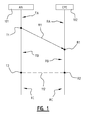
- FIG. 1 illustrates schematically an embodiment of a system according to the present invention.
- the system comprises an access node 101 (AN, such as a FTU-O, G.Fast Transmission Unit-Central Office side) and a customer premises equipment 102 (CPE, such as a FTU-R, G.Fast Transmission Unit - Remote Terminal side) that are remote from each other and that are connected via a communication channel comprising at least a group of vectoring lines (not shown explicitly), i.e., lines for which a vectoring mechanism to cancel crosstalk interference is active.
- the group of vectoring lines is subject to pre-determined transmitted signal power requirements. These requirements constitute frequency-dependent limitations on signal power to reduce interference across neighbouring frequencies, and may take the form of a power spectral density (PSD) mask as imposed by a regulator of a technological specification.
- PSD power spectral density
- the AN 101 operates during period of time TA, which is a period of time before point in time T1, using the following settings: an initial precoding matrix P0, and an initial gain scaling matrix S0.
- the initial precoding matrix P0 serves to compensate the crosstalk over said group of vectoring lines, and has been determined based on estimated expected crosstalk over said group of vectoring lines, obtained for example from a management entity coupled to a detector on the CPE 102 side.
- the initial gain scaling matrix S0 serves to compensate the impact of the initial precoding matrix P0, since signal transmission over the communication channel should comply with (i.e., adhere to) the pre-determined transmitted signal power requirements.
- the CPE 102 may also determine an initial bit loading table b0, which serves to allocate a number of bits to respective carriers of the communication channel, and communicate this initial bit loading table b0 back to the AN 101.
- the CPE 102 operates during period of time RA, which is a period of time before point in time R1, using the inverse of the initial gain scaling matrix S0 in order to equalize the receive carriers, and if applicable the initial bit loading table b0.
- the initial gain scaling matrix S0 and if applicable the initial bit loading table b0 have previously been communicated and agreed upon by the AN 101 and the CPE 102, either amongst themselves or under the management of a separate entity.
- the AN 101 obtains estimated expected crosstalk over said group of vectoring lines, for example in the form of a crosstalk channel matrix, for example, via a management entity coupled to a channel crosstalk detector on the CPE 102 side, and finds that due to some reason the estimated expected crosstalk has changed, requiring that the signal adaptation should be changed in order to compensate the changed estimated expected crosstalk so as to correctly compensate crosstalk over said group of vectoring lines.
- Possible reasons may include disturbance events, such as a joining event and/or a leaving event, wherein respectively a DSL line is activated and/or a DSL line is deactivated. The effects of such events can be detected when a neighbouring line joins or leaves, which impacts the noise floor.
- the AN 101 determines a new precoding matrix P1 for compensating the changed crosstalk channel matrix.
- the new precoding matrix P1 serves to replace the initial precoding matrix P0 that was in use during (at least) period of time TA.
- the AN 101 (or more specifically, the vector controller) also determines a new associated gain scaling matrix S1 based on the new precoding matrix PI, in order to retain compliance with said pre-determined transmitted signal power requirements, to replace S0, and optionally a new bit loading table b1 based on the initial bit loading table b0.
- AN 101 (or more specifically, a timing controller (not shown) of the AN 101) also determines a synchronized point in time T2/R2, on which itself and the CPE 102 agree to adapt signal transmission in a synchronized manner 112.
- T2/R2 time synchronized point in time
- the skilled person is aware of techniques for ensuring the synchronicity between AN 101 and CPE 102.
- AN 101 transmits a transmitter-initiated command 111, sometimes named a TIGA or Transmitter-Initiated Gain Adaptation command, to CPE 102.
- the command 111 comprises information representing the new gain scaling matrix S0 and if applicable the new bit loading table b1. There is no need to include the new precoding matrix P1 in the command 111, since it is only applied at the AN 101 and not at the CPE 102.
- CPE 102 receives the transmitter-initiated command 111.
- the CPE 102 consequently decides to change, at point in time R2, its signal adaptation to using the new settings, comprising the new gain scaling matrix S1 for updated frequency equalization and if applicable the new bit loading table b0.
- the AN 101 may determine at least one intermediate precoding matrix P' configured for gradually replacing P0 with PI, each intermediate precoding matrix P' based on at least a part of P0 and at least a part of PI, in order to replace the initial precoding matrix P0, preferably gradually. Also, it will be appreciated that having a single intermediate precoding matrix P' to go from P0 to P1 may also be termed 'gradually'. Moreover, meanwhile, the AN 101 may determine at least one gain scaling matrix S configured for gain scaling said signals (since signal adaptation with the precoding matrix typically exceeds the pre-determined transmitted signal power requirements to which the group of vectoring lines is subject). The at least one gain scaling matrix S may be determined in such a way, that it complies with the pre-determined transmitted signal power requirements, either singularly or as an aggregate.
- the selection of the part of P0 and the part of P1 may be done by swapping select parts of P0 with corresponding parts of P1.
- the parts may be chosen as one or more elements, one or more sub-matrices, and/or one or more columns and/or rows.
- swapping columns is chosen, since this most closely follows the structure of typical precoding and gain scaling matrices that represent lines in DSL binders.
- both the AN 101 and the CPE 102 coordinate the change in their signal adaptation in a synchronized manner 112.
- the AN 101 writes the new precoding matrix P1 to its memory storage for signal adaptation, as well as the new gain scaling matrix S1 and if applicable the new bit loading table b1.
- the CPE 102 writes the new gain scaling matrix S1 (or a frequency equalization scheme derived from that matrix) and if applicable the new bit loading table b1 to its memory storage for signal adaptation.
- the AN 101 and the CPE 102 make use of compatible signal adaptation settings, such that signal transmission can take place in an effective manner.
- a conservative gain scaling matrix S may be chosen. This matrix is conservative, in that it is chosen to satisfy the pre-determined transmitted signal power requirements for multiple corresponding precoding matrices P (intermediate P' and/or initial P0 and/or new PI). Specifically, by determining a gain scaling matrix S based on (at least one intermediate precoding matrix P' itself based on) the element-wise maximum of the initial precoding matrix P0 and the new precoding matrix PI, that gain scaling matrix S will be compatible in view of the pre-determined transmitted signal power requirements with any matrix that is a combination of the initial precoding matrix P0 and the new precoding matrix P1.
- the at least one intermediate precoding matrix P' may simply be chosen along a linear matrix dimension. For example, a first intermediate precoding matrix P'1 may be determined by combining the leftmost column of the initial precoding matrix P0 and all other columns of the new precoding matrix P1. A second intermediate precoding matrix P'2 may then be determined by combining the two leftmost columns of the initial precoding matrix P0 and all other columns of the new precoding matrix PI, and so on.
- the at least one gain scaling matrix S can be chosen by selecting a migration path from the initial precoding matrix P0 to the new precoding matrix P1 (wherein the migration path represents a possible sequence of intermediate precoding matrices P' allowing to gradually replace P0 with PI), and by computing for each intermediate precoding matrix P' on that migration path its associated gain scaling matrix S', and by choosing from those the gain scaling matrix S that has, for example, a sufficiently high or the highest column sum over all of the associated gain scaling matrices S' for the migration path ( i.e., a valid or respectively the maximal associated gain scaling matrix S').
- the at least one gain scaling matrix S can be chosen by determining some or all possible migration paths, with each migration path for example determined as described hereinabove, and then by selecting the optimal migration path, i.e., the migration path that has the highest potential associated gain scaling matrix S'.
- Figures 2A and 2B illustrate schematically the operation of an embodiment of a method according to the present invention.
- Arrow 221 represents a direct replacement of an initial precoding matrix P0 with a new precoding matrix P1 in a precoder memory storage of a AN's vectoring processor 310 (where precoding takes place).
- Writing the new precoding matrix P1 to memory in a single step (so as to ensure that precoding is done with an effective precoding matrix) requires a very high write-speed memory, which is expensive, since the precoding matrix contains a row and column for every line in the binder, and since the precoding matrix may also be three-dimensional to include a frequency dimension for the frequencies on which the communication channel including the group of vectoring lines operates.
- arrow 222 represents a gradual replacement of an initial precoding matrix P0 with a new precoding matrix P1 in the precoder memory storage of the AN's vectoring processor 310.
- arrow 222 represents two intermediate precoding matrices P'1 and P'2, and an ellipsis sign indicating that there may be zero or more additional intermediate precoding matrices P' in certain embodiments. In other embodiments, there may be as few as only one intermediate precoding matrix P'.
- Each intermediate precoding matrix P' is shown to be based on both the initial precoding matrix P0 and the new precoding matrix P1, for example by including at least a part of P0 and at least a part of P1 - if appropriate, one or more of the parts may be further processed before or after inclusion in P'. This is illustrated visually by including striped columns in the intermediate precoding matrices P'1 and P'2 that represent corresponding columns of the new precoding matrix P1.
- the intermediate precoding matrices P' may comprise other corresponding elements than columns from the initial precoding matrix P0 and the new precoding matrix PI, such as select elements, rows or sub-matrices.
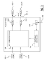
- FIG. 3 illustrates schematically an embodiment of an access node 301 according to the present invention.
- the access node 301 comprises a number of transmitters 303 1-N, each coupled via a subscriber line 304 1-N to a respective receiver 302 1-N (outside of and typically remote from the access node 301).
- the subscriber lines 304 1-N form a group of vectoring lines 304 1-N.
- the group of vectoring lines is subject to pre-determined transmitted signal power requirements, such as a transmit power spectral density (TxPSD) mask, for example imposed by a regulator.
- the access node 301 also comprises a vectoring processor 310 configured for joint signal processing of signals to be transmitted from the transmitters 303 1-N to the receivers 302 1-N.
- the signals are provided respectively from a number of signal sources 320 1-N.
- the access node 301 further also comprises a vectoring controller 330 configured for controlling the joint processing.
- the access node 301 also comprises a management entity 340.
- the vectoring controller 330 is coupled to the vectoring processor 310, such that the vectoring controller 330 may control the joint processing taking place at the vectoring processor 310. In this manner, it is also coupled (indirectly) to the group of vectoring lines 304 1-N.
- the management entity 340 is connected to, for example, a crosstalk measurement or estimation module, that is configured to provide 350 to the management entity 340 measured and/or estimated crosstalk coefficients representing crosstalk interference over the group of vectoring lines 304 1-N.
- the vectoring controller 330 is configured to obtain from the management entity 340 estimated expected crosstalk over the group of vectoring lines 304 1-N, i.e., the crosstalk interference that is expected to occur for signals that are to be transmitted over the group of vectoring lines. In order to pre-compensate the estimated expected crosstalk, the vectoring controller 330 is configured to determine an initial precoding matrix P0 allowing to adapt ( i.e., precode) the signals to be transmitted.
- the vectoring controller 330 is further configured to, after a disturbance event, wherein a subscriber joins or leaves, or the like, obtain from the management entity 340 re-estimated expected crosstalk over said group of vectoring lines. Such disturbance events typically change the crosstalk interference over the group of vectoring lines, and may therefore require a change in the signal adaptation.
- the vectoring controller 330 is configured to determine a new precoding matrix PI, allowing to replace P0. This replacement may be done at a synchronized point in time, as described hereinabove.
- the vectoring controller 330 is configured to determine at least one intermediate precoding matrix P' configured for gradually replacing P0 with P1.
- An example of gradual replacing has been described hereinabove with reference to figure 2 .
- Each such intermediate precoding matrix P' may be based on at least a part of P0 ( e.g., may use a number of columns of P0, without or with some additional processing), and at least a part of P1 ( e.g., may use a number of columns of PI, without or with some additional processing).
- the vectoring controller 330 may also be configured to determine at least one gain scaling matrix S configured for gain scaling the signals to be transmitted.
- the at least one gain scaling matrix S may be based on the at least one precoding matrix P', since precoding may add power to signals (especially in higher frequencies) that can be compensated by gain scaling and frequency equalization.
- the at least one gain scaling matrix S may be determined in compliance with the pre-determined transmitted signal power requirements for each gain scaling matrix S separately, or aggregately over a number of gain scaling matrices S.
- the at least one gain scaling matrix S may also be based on the initial precoding matrix P0 and/or the new precoding matrix P1.
- the vectoring controller 330 is capable of controlling joint signal processing (to be performed at the vectoring processor 310) in such a way that the memory write-speed can be kept low, saving on hardware costs, and that the pre-determined transmitted signal power requirements can be complied with.
- the vectoring processor 310 is meant for joint signal processing of the signals to be transmitted. To that end, it comprises a precoder memory and precoder processor, and a gain scaler memory and gain scaler processor (not shown separately).
- the precoding memory is configured for storing and for replacing (or allowing replacement) of the precoding matrices determined by the vectoring controller 330.
- the precoder processor can use the respective precoding matrices to adapt the signals to be transmitted without needing to provide a very high write-speed memory.
- the gain scaler memory is configured for storing at least one gain scaling matrix S configured for gain scaling said signals, as determined by the vectoring controller 330.
- the gain scaler processor is configured for actually gain scaling said signals using said at least one gain scaling matrix S. By using that at least one gain scaling matrix S, it is possible to comply with the pre-determined transmitted signal power requirements.
- the access node 301 also may comprise a timing controller (not shown in Figure 3 ) configured for determining a synchronized point in time on which to begin using said new precoding matrix P1 in order to pre-compensate said re-estimated expected crosstalk.
- the timing controller is further configured for transmitting or causing the transmission of a transmitter-initiated command to begin using said new precoding matrix P1 at said synchronized point in time, and for, in a period of time before said synchronized point in time, causing said vectoring processor 330 to gradually replace said initial precoding matrix P0 with said at least one intermediate precoding matrix P'.
- the timing controller is configured for, after said synchronized point in time, causing said vectoring processor 330 to use said new precoding matrix P1.
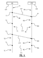
- FIG 4 illustrates schematically another embodiment of a system according to the present invention.
- the system embodiment corresponds to the system embodiment shown in Figure 1 , with the following differences.
- the AN 401 determines sometime during period of time TA that the signal adaptation settings that it uses (as in the system embodiment shown in Figure 1 ) need to be changed due to some disturbance event, such as a joining event or a leaving event, for example detected by a management entity 340. It transmits a preliminary transmitter-initiated command 411 to the CPE 402 comprising a partial update using intermediate precoding matrices P' of a first phase whose associated gain scaling matrices S are equal to the initial gain scaling matrix S0 (which is already known and in use at the CPE 402).
- the AN 401 may therefore update its signal adaptation settings independently. Additionally or alternatively, the partial update may comprise a part of the new signal adaptation settings (i.e., the new precoding matrix P1 and/or a new gain scaling matrix S1 and/or a new bit loading table b1).
- the AN 401 and the CPE 402 change to the preliminary newly determined signal adaptation settings in a coordinated manner 412. In particular, on that point in time, they agree to update their memory storage to the (preliminary) new signal adaptation settings. In some embodiments, it may happen that by point in time T2/R2 the relevant matrix or matrices has or have already been replaced entirely by the gradual replacement described above, in which case no specific action is necessary anymore at point in time T2/R2.
- the AN 401 may transmit an updated transmitter-initiated command 413 to the CPE 402, which receives the command 413 at point in time R3.
- the updated command 413 may represent a second phase of intermediate precoding matrices P' for which it is not necessarily so that their associated gain scaling matrices are equal to the initial gain scaling matrix S0. Additionally or alternatively, the updated command 413 may simply comprise a bigger part of the new signal adaptation settings.
- the AN 401 may gradually replace the precoding matrix P in use by the vectoring processor 310, while still satisfying the pre-determined transmitted signal power requirements by appropriately determining the at least one gain scaling matrix S based on the precoding matrices P in compliance with those requirements.
- the AN 401 and the CPE 401 change to the updated newly determined signal adaptation settings in a coordinated manner 414. In particular, on that point in time, they agree to update their respective memory storages to the (updated) new signal adaptation settings. In some embodiments, it may happen that by point in time T4/R4 the relevant matrix or matrices has or have already been replaced entirely by the gradual replacement described above, in which case no specific action is necessary anymore at point in time T4/R4.
- the AN 401 uses the updated new signal adaptation settings.
- the CPE 402 uses its updated new signal adaptation settings. Since these signal adaptation settings have been determined in a compatible manner, signal transmission between the AN 401 and the CPE 402 can take place in an effective manner. In particular, the pre-determined transmitted signal power requirements are satisfied.
- the advantage to using a preliminary command 411 and an updated command 413, is that the CPE 402 can follow updates at the AN 401 more quickly, and more effectively (since it is made aware of more detailed differences). Moreover, the AN 401 can already commence gradual replacement of its signal adaptation settings in parallel with transmitting the updated command 413, so as to reduce the total time that is needed for completing the entire change.
- program storage devices e.g. digital data storage media, which are machine or computer readable and encode machine-executable or computer-executable programs of instructions, wherein said instructions perform some or all of the steps of said above-described methods.
- the program storage devices may be, e.g. digital memories, magnetic storage media such as magnetic disks and magnetic tapes, hard drives, or optically readable digital data storage media.
- the embodiments are also intended to cover computers programmed to perform said steps of the above-described methods.
- processors may be provided through the use of dedicated hardware as well as hardware capable of executing software in association with appropriate software.
- the functions may be provided by a single dedicated processor, by a single shared processor, or by a plurality of individual processors, some of which may be shared.
- explicit use of the term "processor” or “controller” should not be construed to refer exclusively to hardware capable of executing software, and may implicitly include, without limitation, digital signal processor (DSP) hardware, network processor, application specific integrated circuit (ASIC), field programmable gate array (FPGA), read only memory (ROM) for storing software, random access memory (RAM), and non volatile storage.
- DSP digital signal processor
- ASIC application specific integrated circuit
- FPGA field programmable gate array
- ROM read only memory
- RAM random access memory
- any switches shown in the figures are conceptual only. Their function may be carried out through the operation of program logic, through dedicated logic, through the interaction of program control and dedicated logic, or even manually, the particular technique being selectable by the implementer as more specifically understood from the context.
Landscapes
- Engineering & Computer Science (AREA)
- Computer Networks & Wireless Communication (AREA)
- Signal Processing (AREA)
- Cable Transmission Systems, Equalization Of Radio And Reduction Of Echo (AREA)
Abstract
Description
- The field of the invention relates to joint signal processing. Particular embodiments relate to a method and a vectoring controller for controlling joint signal processing, a vectoring processor for joint signal processing, an access node, a communication system, and a computer program product for controlling joint signal processing.
- Communication systems liable to interference, especially crosstalk interference, utilize precoding to compensate the effect of the interference, and gain scaling to compensate the effect of the precoding. Typically, the interference changes over time due to disturbance events (e.g., a modem activation, deactivation or reactivation), such that new precoding schemes and, consequently, new gain scaling schemes must be set. The setting of these new schemes can be initiated from the transmitter-side (Transmitter-Initiated Gain Adaptation, TIGA). In particular, transmitters in DSL systems initiate such signal adaptation. To ensure effectiveness of the communication system, it is desired that such signal adaptation takes place in a coordinated way.
- Known systems coordinate signal adaptation by agreeing on a synchronized point in time on which to set signal adaptation to use the new schemes. However, given the very high-speed operation of communication systems, switching to such new schemes requires that the new schemes are electronically stored very quickly from one symbol of the signal to the next. This in turn requires very high-cost hardware, since the write-speed of the electronic memory must be very high.
- It is an object of embodiments of the present invention to reduce write speed requirements for coordinated signal adaptation. Other objects of embodiments of the present invention are to reduce the cost of hardware provisioning and to adhere to regulations.
- According to an aspect of the invention, there is provided a method for controlling joint signal processing of signals to be transmitted respectively from a number of transmitters to a number of receivers via a group of vectoring lines subject to pre-determined transmitted signal power requirements. Said method comprises: obtaining estimated expected crosstalk over said group of vectoring lines; determining an initial precoding matrix P0 configured for adapting said signals in order to pre-compensate said estimated expected crosstalk; obtaining re-estimated expected crosstalk over said group of vectoring lines after a disturbance event; determining a new precoding matrix P1 configured for pre-compensating said re-estimated expected crosstalk; determining at least one intermediate precoding matrix P' configured for gradually replacing P0 with PI, each intermediate precoding matrix P' based on at least a part of P0 and at least a part of PI; and determining at least one gain scaling matrix S configured for gain scaling said signals, based on said at least one precoding matrix P', in compliance with said pre-determined transmitted signal power requirements.
- Said pre-determined transmitted signal power requirements may constitute frequency-dependent limitations on signal power to reduce interference across neighbouring frequencies, such as a transmit power spectral density (TxPSD) mask.
- Embodiments of the present invention are based inter alia on the inventive insight that determining one or more intermediate precoding matrices P' configured to replace the initial precoding matrix P' allows for gradual replacement up to the new precoding matrix P1 after a disturbance event, which may reduce the need for very high write-speed hardware, and consequently allow for cheaper hardware provisioning, while taking into account that the gain scaling, for each separate symbol of the signal to be transmitted or over a number of symbols, should still comply with the pre-determined transmitted signal power requirements.
- Specifically, by determining one or more intermediate precoding matrices P' that contain respective parts of P0 and PI, it is possible to strive to multiple objects of embodiments of the invention concurrently. Moreover, the time after the disturbance event can thus be used more efficiently.
- In an embodiment, said at least one intermediate precoding matrix P' is determined by: swapping one or more elements of P0 for one or more corresponding elements of PI; swapping one or more sub-matrices of P0 for one or more corresponding sub-matrices of PI; swapping one or more columns of P0 for one or more corresponding columns of PI; or swapping one or more rows of P0 for one or more corresponding rows of P1.
- In this manner, the replacement can be performed in an efficient manner, since swapping of the listed parts can be performed efficiently in existing hardware.
- In an embodiment, said at least one intermediate precoding matrix P' is determined by iteratively selecting one or more parts of P0 to be replaced with one or more corresponding parts of P1 along a linear matrix dimension (e.g. from left to right, from right to left, from top to bottom or from bottom to top).
- In this manner, a limited amount of resources is required for the selection process.
- In another embodiment, said at least one intermediate precoding matrix P' is determined by selecting for each element of P' the maximum of the corresponding elements of P0 and P1.
- In this manner, a conservative intermediate precoding matrix P' can be determined, such that associated gain scaling matrices S may be determined with greater liberty.
- In yet another embodiment: said at least one intermediate precoding matrix P' is determined by selecting a migration path from P0 to PI; for each intermediate precoding matrix P' of said migration path, an associated gain scaling matrix S' is computed; and said at least one gain scaling matrix S is determined by selecting a valid, preferably the maximal, associated gain scaling matrix S' from amongst said associated gain scaling matrices S'.
- In this manner, the one or more gain scaling matrices S can be determined efficiently yet effectively.
- In a further developed embodiment, selecting a migration path is performed using a search algorithm or heuristic, in order to optimize a pre-determined condition.
The skilled person will understand that example pre-determined conditions may comprise such conditions as: achieving a highest possible data rate during transmission, achieving least complexity for writing / reading (in a particular example, by addressing columns of the corresponding matrix as sequentially as possible), optimizing transmission for prioritized user classes or users (e.g. by giving priority to business users over residential users), or any combination thereof, etc. Moreover, the skilled person will appreciate that the notion 'to optimize' is to be seen from a computer science / artificial intelligence point of view, i.e. striving for an optimal or sub-optimal solution to a condition. Example search algorithms or heuristics for such optimization may comprise simulated annealing, reinforcement learning, and gradient-based optimization. - In yet another embodiment: a plurality of potential migration paths from P0 to P1 are determined, each potential migration path containing at least one potential intermediate precoding matrix P'; for each potential migration path of said plurality of potential migration paths, for each potential intermediate precoding matrix P' of said potential migration path, a potential associated gain scaling matrix S' is computed; for each potential migration path of said plurality of potential migration paths, a valid, preferably the maximal, potential associated gain scaling matrix S' for that potential migration path is selected; said at least one gain scaling matrix S is determined by selecting a valid, preferably the maximal, associated gain scaling matrix S' from amongst said valid or maximal potential associated gain scaling matrices S'; and said at least one intermediate precoding matrix P' is determined by selecting the migration path from amongst said potential migration paths that corresponds to said selected valid or maximal associated gain scaling matrix S'.
- In this manner, the one or more gain scaling matrices S can be determined efficiently yet very effectively.
- In a further developed embodiment, said or each migration path comprises at least a phase containing one or more intermediate precoding matrices P' whose at least one associated gain scaling matrix S is equal to an initial gain scaling matrix S0 associated with said initial precoding matrix P0.
- In this manner, the phase can be used efficiently to commence gradual replacement of the initial precoding matrix P0 without endangering the compatibility of the gain scaling matrix S in view of the pre-determined transmitted signal power requirements.
- In an embodiment, the method comprises: determining a synchronized point in time on which to begin using said new precoding matrix P1 in order to pre-compensate said re-estimated expected crosstalk; transmitting a transmitter-initiated command to begin using said new precoding matrix P1 at said synchronized point in time; in a period of time before said synchronized point in time, gradually replacing said initial precoding matrix P0 with said at least one intermediate precoding matrix P'; and after said synchronized point in time, using said new precoding matrix P1.
- In this manner, signal adaptation can be coordinated while allowing the use of less costly hardware.
- In another embodiment, the method comprises determining at least one bit loading table b, based on said at least one intermediate precoding matrix P', in order to match an observed signal-to-noise ratio.
- In this manner, it is possible to adaptively assign a different number of bits to each line according to changing channel conditions due to a disturbance event.
- In an embodiment, signal transmission via said communication channel adheres to a communication technique, such as G.Fast, characterized by potentially suffering from relative crosstalk interference levels greater than -6 dB.
- According to another aspect of the invention, there is provided a vectoring controller for controlling joint signal processing of signals to be transmitted respectively from a number of transmitters to a number of receivers via a group of vectoring lines subject to pre-determined transmitted signal power requirements. Said vectoring controller comprises a management entity interface and a processor. The management entity interface is configured for: obtaining estimated expected crosstalk over said group of vectoring lines; and obtaining re-estimated expected crosstalk over said group of vectoring lines after a disturbance event. The processor is configured for: determining an initial precoding matrix P0 configured for adapting said signals in order to pre-compensate said estimated expected crosstalk; determining a new precoding matrix P1 configured for pre-compensating said re-estimated expected crosstalk; determining at least one intermediate precoding matrix P' configured for gradually replacing P0 with PI, each intermediate precoding matrix P' based on at least a part of P0 and at least a part of PI; and determining at least one gain scaling matrix S configured for gain scaling said signals, based on said at least one precoding matrix P', in compliance with said pre-determined transmitted signal power requirements.
- The skilled person will understand that the hereinabove described considerations and advantages also apply for embodiments of the vectoring controller, mutatis mutandis.
- In an embodiment, said processor is configured for performing all of the steps of any one of the method embodiments described hereinabove.
- According to another aspect of the invention, there is provided a vectoring processor for joint signal processing of signals to be transmitted respectively from a number of transmitters to a number of receivers via a group of vectoring lines subject to pre-determined transmitted signal power requirements. Said vectoring processor comprises a precoder memory and a precoder processor, and a gain scaler memory and a gain scaler processor. The precoder memory is configured for: storing an initial precoding matrix P0 configured for adapting said signals in order to pre-compensate estimated expected crosstalk over said group of vectoring lines; gradually replacing said initial precoding matrix P0 with at least one intermediate precoding matrix P', each intermediate precoding matrix P' based on at least a part of P0 and at least a part of a new precoding matrix PI, said new precoding matrix P1 being configured for pre-compensating re-estimated expected crosstalk over said group of vectoring lines after a disturbance event; and replacing said at least one intermediate precoding matrix P' with said new precoding matrix P1. The precoder processor is configured for: adapting said signals using said initial precoding matrix P0 stored in said precoder memory; adapting said signals using said at least one intermediate precoding matrix P' stored in said precoder memory; and adapting said signals using said new precoding matrix P1 stored in said precoder memory. The gain scaler memory is configured for storing at least one gain scaling matrix S configured for gain scaling said signals, based on said at least one precoding matrix P', in compliance with said pre-determined transmitted signal power requirements. The gain scaler processor is configured for gain scaling said signals using said at least one gain scaling matrix S stored in said gain scaler memory.
- The skilled person will understand that the hereinabove described considerations and advantages also apply for embodiments of the vectoring processor, mutatis mutandis.
- According to another aspect of the invention, there is provided an access node comprising: a vectoring controller described hereinabove; a vectoring processor described hereinabove, said vectoring processor being coupled to said vectoring controller and to a group of vectoring lines connecting a number of transmitters and a respective number of receivers; and a management entity. The management entity is configured for: providing to said vectoring controller estimated expected crosstalk over said group of vectoring lines; detecting a disturbance event on said group of vectoring lines; and providing to said vectoring controller re-estimated expected crosstalk over said group of vectoring lines after detecting said disturbance event.
- The skilled person will understand that the hereinabove described considerations and advantages also apply for embodiments of the access node, mutatis mutandis.
- In an embodiment, the access node comprises a timing controller configured for: determining a synchronized point in time on which to begin using said new precoding matrix P1 in order to pre-compensate said re-estimated expected crosstalk; transmitting a transmitter-initiated command to begin using said new precoding matrix P1 at said synchronized point in time; in a period of time before said synchronized point in time, causing said vectoring processor to gradually replace said initial precoding matrix P0 with said at least one intermediate precoding matrix P'; and after said synchronized point in time, causing said vectoring processor to use said new precoding matrix P1.
- According to another aspect of the invention, there is provided a communication system comprising a number of access nodes described hereinabove, each access node connected to a number of CPEs, customer premises equipment, via a group of vectoring lines.
- The skilled person will understand that the hereinabove described considerations and advantages also apply for embodiments of the communication system, mutatis mutandis.
- According to another aspect of the invention, there is provided a computer program product comprising computer-executable instructions for performing a method when the program is run on a computer, the method comprising the steps of any one of the methods described hereinabove.
- The skilled person will understand that the hereinabove described considerations and advantages also apply for embodiments of the computer program product, mutatis mutandis.
- The accompanying drawings are used to illustrate presently preferred non-limiting exemplary embodiments according to the present invention. The above and other advantages of the features of embodiments according to the invention and objects of the invention will become more apparent and the invention will be better understood from the following detailed description when read in conjunction with the accompanying drawings, in which:
-
Figure 1 illustrates schematically an embodiment of a system according to the present invention; -
Figures 2A and 2B illustrate schematically operation of an embodiment of a method according to the present invention; -
Figure 3 illustrates schematically operation of an embodiment of an access node according to the present invention; and -
Figure 4 illustrates schematically another embodiment of a system according to the present invention. -
Figure 1 illustrates schematically an embodiment of a system according to the present invention. The system comprises an access node 101 (AN, such as a FTU-O, G.Fast Transmission Unit-Central Office side) and a customer premises equipment 102 (CPE, such as a FTU-R, G.Fast Transmission Unit - Remote Terminal side) that are remote from each other and that are connected via a communication channel comprising at least a group of vectoring lines (not shown explicitly), i.e., lines for which a vectoring mechanism to cancel crosstalk interference is active. The group of vectoring lines is subject to pre-determined transmitted signal power requirements. These requirements constitute frequency-dependent limitations on signal power to reduce interference across neighbouring frequencies, and may take the form of a power spectral density (PSD) mask as imposed by a regulator of a technological specification. - The
AN 101 operates during period of time TA, which is a period of time before point in time T1, using the following settings: an initial precoding matrix P0, and an initial gain scaling matrix S0. The initial precoding matrix P0 serves to compensate the crosstalk over said group of vectoring lines, and has been determined based on estimated expected crosstalk over said group of vectoring lines, obtained for example from a management entity coupled to a detector on theCPE 102 side. The initial gain scaling matrix S0 serves to compensate the impact of the initial precoding matrix P0, since signal transmission over the communication channel should comply with (i.e., adhere to) the pre-determined transmitted signal power requirements.
Moreover, in some embodiments, theCPE 102 may also determine an initial bit loading table b0, which serves to allocate a number of bits to respective carriers of the communication channel, and communicate this initial bit loading table b0 back to theAN 101. - The
CPE 102 operates during period of time RA, which is a period of time before point in time R1, using the inverse of the initial gain scaling matrix S0 in order to equalize the receive carriers, and if applicable the initial bit loading table b0. - For the purposes of this example, we assume that the initial gain scaling matrix S0 and if applicable the initial bit loading table b0 have previously been communicated and agreed upon by the
AN 101 and theCPE 102, either amongst themselves or under the management of a separate entity. - Before point in time T1, the
AN 101 obtains estimated expected crosstalk over said group of vectoring lines, for example in the form of a crosstalk channel matrix, for example, via a management entity coupled to a channel crosstalk detector on theCPE 102 side, and finds that due to some reason the estimated expected crosstalk has changed, requiring that the signal adaptation should be changed in order to compensate the changed estimated expected crosstalk so as to correctly compensate crosstalk over said group of vectoring lines. Possible reasons may include disturbance events, such as a joining event and/or a leaving event, wherein respectively a DSL line is activated and/or a DSL line is deactivated. The effects of such events can be detected when a neighbouring line joins or leaves, which impacts the noise floor. - In response to finding that the signal adaptation should be changed, the AN 101 (or more specifically, a vector controller (not shown) of the AN 101) determines a new precoding matrix P1 for compensating the changed crosstalk channel matrix. The new precoding matrix P1 serves to replace the initial precoding matrix P0 that was in use during (at least) period of time TA. The AN 101 (or more specifically, the vector controller) also determines a new associated gain scaling matrix S1 based on the new precoding matrix PI, in order to retain compliance with said pre-determined transmitted signal power requirements, to replace S0, and optionally a new bit loading table b1 based on the initial bit loading table b0.
AN 101 (or more specifically, a timing controller (not shown) of the AN 101) also determines a synchronized point in time T2/R2, on which itself and theCPE 102 agree to adapt signal transmission in asynchronized manner 112. The skilled person is aware of techniques for ensuring the synchronicity between AN 101 andCPE 102. - At point in time T1 AN 101 transmits a transmitter-initiated
command 111, sometimes named a TIGA or Transmitter-Initiated Gain Adaptation command, toCPE 102. Thecommand 111 comprises information representing the new gain scaling matrix S0 and if applicable the new bit loading table b1. There is no need to include the new precoding matrix P1 in thecommand 111, since it is only applied at theAN 101 and not at theCPE 102. - In the present figure, it has been chosen to represent the transmission of the
command 111 as a single arrow, but it will be understood that the principles of good engineering may require acknowledgements and the like, which are not dealt with in detail in this specification. - At point in
time R1 CPE 102 receives the transmitter-initiatedcommand 111. TheCPE 102 consequently decides to change, at point in time R2, its signal adaptation to using the new settings, comprising the new gain scaling matrix S1 for updated frequency equalization and if applicable the new bit loading table b0. - During TB (after and/or before point in time R1), and optionally even during TA before point in time T1, the
AN 101 may determine at least one intermediate precoding matrix P' configured for gradually replacing P0 with PI, each intermediate precoding matrix P' based on at least a part of P0 and at least a part of PI, in order to replace the initial precoding matrix P0, preferably gradually. Also, it will be appreciated that having a single intermediate precoding matrix P' to go from P0 to P1 may also be termed 'gradually'. Moreover, meanwhile, theAN 101 may determine at least one gain scaling matrix S configured for gain scaling said signals (since signal adaptation with the precoding matrix typically exceeds the pre-determined transmitted signal power requirements to which the group of vectoring lines is subject). The at least one gain scaling matrix S may be determined in such a way, that it complies with the pre-determined transmitted signal power requirements, either singularly or as an aggregate. - In particular embodiments, the selection of the part of P0 and the part of P1 may be done by swapping select parts of P0 with corresponding parts of P1. In some embodiments, the parts may be chosen as one or more elements, one or more sub-matrices, and/or one or more columns and/or rows. In preferred embodiments, swapping columns is chosen, since this most closely follows the structure of typical precoding and gain scaling matrices that represent lines in DSL binders.
- At point in time T2/R2 both the
AN 101 and theCPE 102 coordinate the change in their signal adaptation in asynchronized manner 112. This means that theAN 101 writes the new precoding matrix P1 to its memory storage for signal adaptation, as well as the new gain scaling matrix S1 and if applicable the new bit loading table b1. Likewise, theCPE 102 writes the new gain scaling matrix S1 (or a frequency equalization scheme derived from that matrix) and if applicable the new bit loading table b1 to its memory storage for signal adaptation. - During period of time TC for the
AN 101 and period of time RC for theCPE 102, theAN 101 and theCPE 102 make use of compatible signal adaptation settings, such that signal transmission can take place in an effective manner. - In some embodiments, a conservative gain scaling matrix S may be chosen. This matrix is conservative, in that it is chosen to satisfy the pre-determined transmitted signal power requirements for multiple corresponding precoding matrices P (intermediate P' and/or initial P0 and/or new PI). Specifically, by determining a gain scaling matrix S based on (at least one intermediate precoding matrix P' itself based on) the element-wise maximum of the initial precoding matrix P0 and the new precoding matrix PI, that gain scaling matrix S will be compatible in view of the pre-determined transmitted signal power requirements with any matrix that is a combination of the initial precoding matrix P0 and the new precoding matrix P1.
- In certain embodiments, the at least one intermediate precoding matrix P' may simply be chosen along a linear matrix dimension. For example, a first intermediate precoding matrix P'1 may be determined by combining the leftmost column of the initial precoding matrix P0 and all other columns of the new precoding matrix P1. A second intermediate precoding matrix P'2 may then be determined by combining the two leftmost columns of the initial precoding matrix P0 and all other columns of the new precoding matrix PI, and so on.
- In other embodiments, the at least one gain scaling matrix S can be chosen by selecting a migration path from the initial precoding matrix P0 to the new precoding matrix P1 (wherein the migration path represents a possible sequence of intermediate precoding matrices P' allowing to gradually replace P0 with PI), and by computing for each intermediate precoding matrix P' on that migration path its associated gain scaling matrix S', and by choosing from those the gain scaling matrix S that has, for example, a sufficiently high or the highest column sum over all of the associated gain scaling matrices S' for the migration path (i.e., a valid or respectively the maximal associated gain scaling matrix S').
Alternatively, the at least one gain scaling matrix S can be chosen by determining some or all possible migration paths, with each migration path for example determined as described hereinabove, and then by selecting the optimal migration path, i.e., the migration path that has the highest potential associated gain scaling matrix S'. -
Figures 2A and 2B illustrate schematically the operation of an embodiment of a method according to the present invention. -
Arrow 221 represents a direct replacement of an initial precoding matrix P0 with a new precoding matrix P1 in a precoder memory storage of a AN's vectoring processor 310 (where precoding takes place). Writing the new precoding matrix P1 to memory in a single step (so as to ensure that precoding is done with an effective precoding matrix) requires a very high write-speed memory, which is expensive, since the precoding matrix contains a row and column for every line in the binder, and since the precoding matrix may also be three-dimensional to include a frequency dimension for the frequencies on which the communication channel including the group of vectoring lines operates. - By contrast,
arrow 222 represents a gradual replacement of an initial precoding matrix P0 with a new precoding matrix P1 in the precoder memory storage of the AN'svectoring processor 310. Along thearrow 222 are shown two intermediate precoding matrices P'1 and P'2, and an ellipsis sign indicating that there may be zero or more additional intermediate precoding matrices P' in certain embodiments. In other embodiments, there may be as few as only one intermediate precoding matrix P'.
Each intermediate precoding matrix P' is shown to be based on both the initial precoding matrix P0 and the new precoding matrix P1, for example by including at least a part of P0 and at least a part of P1 - if appropriate, one or more of the parts may be further processed before or after inclusion in P'. This is illustrated visually by including striped columns in the intermediate precoding matrices P'1 and P'2 that represent corresponding columns of the new precoding matrix P1. In other embodiments, the intermediate precoding matrices P' may comprise other corresponding elements than columns from the initial precoding matrix P0 and the new precoding matrix PI, such as select elements, rows or sub-matrices. It will be understood that by determining these intermediate precoding matrices P'1 and P'2 based on P0 and P1 in such a manner, it is possible to gradually replace the initial precoding matrix P0 with the new precoding matrix P1 and thus to save on the write-speed requirements for the memory storage that is configured to store the relevant matrices for signal adaptation, and ultimately to use less expensive hardware. Moreover, by determining one or more associated gain scaling matrices S for said at least one intermediate precoding matrix P' in compliance with pre-determined transmitted signal power requirements, it can be prevented that those power requirements would be exceeded by precoding using said at least one intermediate precoding matrix P'. The one or more associated gain scaling matrices S may be determined so as to comply with the pre-determined power requirements for each separate intermediate precoding matrix P', or over an aggregated number of intermediate precoding matrices P'. -
Figure 3 illustrates schematically an embodiment of an access node 301 according to the present invention. The access node 301 comprises a number oftransmitters 303 1-N, each coupled via asubscriber line 304 1-N to arespective receiver 302 1-N (outside of and typically remote from the access node 301). In this example, thesubscriber lines 304 1-N form a group of vectoringlines 304 1-N. The group of vectoring lines is subject to pre-determined transmitted signal power requirements, such as a transmit power spectral density (TxPSD) mask, for example imposed by a regulator. The access node 301 also comprises avectoring processor 310 configured for joint signal processing of signals to be transmitted from thetransmitters 303 1-N to thereceivers 302 1-N. The signals are provided respectively from a number ofsignal sources 320 1-N. The access node 301 further also comprises avectoring controller 330 configured for controlling the joint processing. The access node 301 also comprises amanagement entity 340. - The vectoring
controller 330 is coupled to thevectoring processor 310, such that the vectoringcontroller 330 may control the joint processing taking place at thevectoring processor 310. In this manner, it is also coupled (indirectly) to the group of vectoringlines 304 1-N. Themanagement entity 340 is connected to, for example, a crosstalk measurement or estimation module, that is configured to provide 350 to themanagement entity 340 measured and/or estimated crosstalk coefficients representing crosstalk interference over the group of vectoringlines 304 1-N. - The vectoring
controller 330 is configured to obtain from themanagement entity 340 estimated expected crosstalk over the group of vectoringlines 304 1-N, i.e., the crosstalk interference that is expected to occur for signals that are to be transmitted over the group of vectoring lines. In order to pre-compensate the estimated expected crosstalk, the vectoringcontroller 330 is configured to determine an initial precoding matrix P0 allowing to adapt (i.e., precode) the signals to be transmitted. - The vectoring
controller 330 is further configured to, after a disturbance event, wherein a subscriber joins or leaves, or the like, obtain from themanagement entity 340 re-estimated expected crosstalk over said group of vectoring lines. Such disturbance events typically change the crosstalk interference over the group of vectoring lines, and may therefore require a change in the signal adaptation. In order to pre-compensate the re-estimated expected crosstalk, the vectoringcontroller 330 is configured to determine a new precoding matrix PI, allowing to replace P0. This replacement may be done at a synchronized point in time, as described hereinabove. - In order to provide a more gradual replacement, the vectoring
controller 330 is configured to determine at least one intermediate precoding matrix P' configured for gradually replacing P0 with P1. An example of gradual replacing has been described hereinabove with reference tofigure 2 . Each such intermediate precoding matrix P' may be based on at least a part of P0 (e.g., may use a number of columns of P0, without or with some additional processing), and at least a part of P1 (e.g., may use a number of columns of PI, without or with some additional processing). - In order to comply with pre-determined transmitted signal power requirements to which the group of vectoring lines may be subject, the vectoring
controller 330 may also be configured to determine at least one gain scaling matrix S configured for gain scaling the signals to be transmitted. The at least one gain scaling matrix S may be based on the at least one precoding matrix P', since precoding may add power to signals (especially in higher frequencies) that can be compensated by gain scaling and frequency equalization. The at least one gain scaling matrix S may be determined in compliance with the pre-determined transmitted signal power requirements for each gain scaling matrix S separately, or aggregately over a number of gain scaling matrices S. The at least one gain scaling matrix S may also be based on the initial precoding matrix P0 and/or the new precoding matrix P1. - In this manner, the vectoring
controller 330 is capable of controlling joint signal processing (to be performed at the vectoring processor 310) in such a way that the memory write-speed can be kept low, saving on hardware costs, and that the pre-determined transmitted signal power requirements can be complied with. - The vectoring
processor 310 is meant for joint signal processing of the signals to be transmitted. To that end, it comprises a precoder memory and precoder processor, and a gain scaler memory and gain scaler processor (not shown separately). - The precoding memory is configured for storing and for replacing (or allowing replacement) of the precoding matrices determined by the vectoring
controller 330. By allowing gradual replacement of the precoding matrices stored in the precoding memory, the precoder processor can use the respective precoding matrices to adapt the signals to be transmitted without needing to provide a very high write-speed memory. - The gain scaler memory is configured for storing at least one gain scaling matrix S configured for gain scaling said signals, as determined by the vectoring
controller 330. The gain scaler processor is configured for actually gain scaling said signals using said at least one gain scaling matrix S. By using that at least one gain scaling matrix S, it is possible to comply with the pre-determined transmitted signal power requirements. - In some embodiments, the access node 301 also may comprise a timing controller (not shown in
Figure 3 ) configured for determining a synchronized point in time on which to begin using said new precoding matrix P1 in order to pre-compensate said re-estimated expected crosstalk. The timing controller is further configured for transmitting or causing the transmission of a transmitter-initiated command to begin using said new precoding matrix P1 at said synchronized point in time, and for, in a period of time before said synchronized point in time, causing saidvectoring processor 330 to gradually replace said initial precoding matrix P0 with said at least one intermediate precoding matrix P'. Also, the timing controller is configured for, after said synchronized point in time, causing saidvectoring processor 330 to use said new precoding matrix P1. -
Figure 4 illustrates schematically another embodiment of a system according to the present invention. The system embodiment corresponds to the system embodiment shown inFigure 1 , with the following differences.
TheAN 401 determines sometime during period of time TA that the signal adaptation settings that it uses (as in the system embodiment shown inFigure 1 ) need to be changed due to some disturbance event, such as a joining event or a leaving event, for example detected by amanagement entity 340. It transmits a preliminary transmitter-initiatedcommand 411 to theCPE 402 comprising a partial update using intermediate precoding matrices P' of a first phase whose associated gain scaling matrices S are equal to the initial gain scaling matrix S0 (which is already known and in use at the CPE 402). During the period of time TB, and even before point in time R1, theAN 401 may therefore update its signal adaptation settings independently. Additionally or alternatively, the partial update may comprise a part of the new signal adaptation settings (i.e., the new precoding matrix P1 and/or a new gain scaling matrix S1 and/or a new bit loading table b1). - At point in time T2/R2 the
AN 401 and theCPE 402 change to the preliminary newly determined signal adaptation settings in acoordinated manner 412. In particular, on that point in time, they agree to update their memory storage to the (preliminary) new signal adaptation settings. In some embodiments, it may happen that by point in time T2/R2 the relevant matrix or matrices has or have already been replaced entirely by the gradual replacement described above, in which case no specific action is necessary anymore at point in time T2/R2. - At point in time T3, the
AN 401 may transmit an updated transmitter-initiatedcommand 413 to theCPE 402, which receives thecommand 413 at point in time R3. The updatedcommand 413 may represent a second phase of intermediate precoding matrices P' for which it is not necessarily so that their associated gain scaling matrices are equal to the initial gain scaling matrix S0. Additionally or alternatively, the updatedcommand 413 may simply comprise a bigger part of the new signal adaptation settings. - During period of time TD (before and/or after point in time R3), and optionally even during period of time TC before point in time T3, the
AN 401 may gradually replace the precoding matrix P in use by the vectoringprocessor 310, while still satisfying the pre-determined transmitted signal power requirements by appropriately determining the at least one gain scaling matrix S based on the precoding matrices P in compliance with those requirements. - At point in time T4/R4, the
AN 401 and theCPE 401 change to the updated newly determined signal adaptation settings in acoordinated manner 414. In particular, on that point in time, they agree to update their respective memory storages to the (updated) new signal adaptation settings. In some embodiments, it may happen that by point in time T4/R4 the relevant matrix or matrices has or have already been replaced entirely by the gradual replacement described above, in which case no specific action is necessary anymore at point in time T4/R4. - During period of time TE, the
AN 401 uses the updated new signal adaptation settings. During period of time RE, theCPE 402 uses its updated new signal adaptation settings. Since these signal adaptation settings have been determined in a compatible manner, signal transmission between theAN 401 and theCPE 402 can take place in an effective manner. In particular, the pre-determined transmitted signal power requirements are satisfied. - The advantage to using a
preliminary command 411 and an updatedcommand 413, is that theCPE 402 can follow updates at theAN 401 more quickly, and more effectively (since it is made aware of more detailed differences). Moreover, theAN 401 can already commence gradual replacement of its signal adaptation settings in parallel with transmitting the updatedcommand 413, so as to reduce the total time that is needed for completing the entire change. - A person of skill in the art would readily recognize that steps of various above-described methods can be performed by programmed computers. Herein, some embodiments are also intended to cover program storage devices, e.g. digital data storage media, which are machine or computer readable and encode machine-executable or computer-executable programs of instructions, wherein said instructions perform some or all of the steps of said above-described methods. The program storage devices may be, e.g. digital memories, magnetic storage media such as magnetic disks and magnetic tapes, hard drives, or optically readable digital data storage media. The embodiments are also intended to cover computers programmed to perform said steps of the above-described methods.
- The description and drawings merely illustrate the principles of the invention. It will thus be appreciated that those skilled in the art will be able to devise various arrangements that, although not explicitly described or shown herein, embody the principles of the invention and are included within its spirit and scope. Furthermore, all examples recited herein are principally intended expressly to be only for pedagogical purposes to aid the reader in understanding the principles of the invention and the concepts contributed by the inventor(s) to furthering the art, and are to be construed as being without limitation to such specifically recited examples and conditions. Moreover, all statements herein reciting principles, aspects, and embodiments of the invention, as well as specific examples thereof, are intended to encompass equivalents thereof.
- The functions of the various elements shown in the figures, including any functional blocks labelled as "processors", may be provided through the use of dedicated hardware as well as hardware capable of executing software in association with appropriate software. When provided by a processor, the functions may be provided by a single dedicated processor, by a single shared processor, or by a plurality of individual processors, some of which may be shared. Moreover, explicit use of the term "processor" or "controller" should not be construed to refer exclusively to hardware capable of executing software, and may implicitly include, without limitation, digital signal processor (DSP) hardware, network processor, application specific integrated circuit (ASIC), field programmable gate array (FPGA), read only memory (ROM) for storing software, random access memory (RAM), and non volatile storage. Other hardware, conventional and/or custom, may also be included. Similarly, any switches shown in the figures are conceptual only. Their function may be carried out through the operation of program logic, through dedicated logic, through the interaction of program control and dedicated logic, or even manually, the particular technique being selectable by the implementer as more specifically understood from the context.
- It should be appreciated by those skilled in the art that any block diagrams herein represent conceptual views of illustrative circuitry embodying the principles of the invention. Similarly, it will be appreciated that any flow charts, flow diagrams, state transition diagrams, pseudo code, and the like represent various processes which may be substantially represented in computer readable medium and so executed by a computer.
- Whilst the principles of the invention have been set out above in connection with specific embodiments, it is to be understood that this description is merely made by way of example and not as a limitation of the scope of protection which is determined by the appended claims.
Claims (15)
- A method for controlling joint signal processing of signals to be transmitted respectively from a number of transmitters to a number of receivers via a group of vectoring lines subject to pre-determined transmitted signal power requirements; said method comprising:- obtaining estimated expected crosstalk over said group of vectoring lines;- determining an initial precoding matrix P0 configured for adapting said signals in order to pre-compensate said estimated expected crosstalk;- obtaining re-estimated expected crosstalk over said group of vectoring lines after a disturbance event;- determining a new precoding matrix P1 configured for pre-compensating said re-estimated expected crosstalk;- determining at least one intermediate precoding matrix P' configured for gradually replacing P0 with PI, each intermediate precoding matrix P' based on at least a part of P0 and at least a part of PI; and- determining at least one gain scaling matrix S configured for gain scaling said signals, based on said at least one precoding matrix P', in compliance with said pre-determined transmitted signal power requirements.
- The method of claim 1, wherein said at least one intermediate precoding matrix P' is determined by:- swapping one or more elements of P0 for one or more corresponding elements of PI;- swapping one or more sub-matrices of P0 for one or more corresponding sub-matrices of PI;- swapping one or more columns of P0 for one or more corresponding columns of PI; or- swapping one or more rows of P0 for one or more corresponding rows of P1.
- The method of any one of the claims 1-2, wherein said at least one intermediate precoding matrix P' is determined by iteratively selecting one or more parts of P0 to be replaced with one or more corresponding parts of P1 along a linear matrix dimension.
- The method of any one of the claims 1-2, wherein said at least one intermediate precoding matrix P' is determined by selecting for each element of P' the extremum of the corresponding elements of P0 and P1.
- The method of any one of the claims 1-2, wherein:- said at least one intermediate precoding matrix P' is determined by selecting a migration path from P0 to P1;- for each intermediate precoding matrix P' of said migration path, an associated gain scaling matrix S' is computed; and- said at least one gain scaling matrix S is determined by selecting a valid, preferably the maximal, associated gain scaling matrix S' from amongst said associated gain scaling matrices S'.
- The method of any one of the claims 1-2, wherein:- a plurality of potential migration paths from P0 to P1 are determined, each potential migration path containing at least one potential intermediate precoding matrix P';- for each potential migration path of said plurality of potential migration paths, for each potential intermediate precoding matrix P' of said potential migration path, a potential associated gain scaling matrix S' is computed;- for each potential migration path of said plurality of potential migration paths, a valid, preferably the maximal, potential associated gain scaling matrix S' for that potential migration path is selected;- said at least one gain scaling matrix S is determined by selecting a valid, preferably the maximal, associated gain scaling matrix S' from amongst said valid or maximal potential associated gain scaling matrices S'; and- said at least one intermediate precoding matrix P' is determined by selecting the migration path from amongst said potential migration paths that corresponds to said selected valid or maximal associated gain scaling matrix S'.
- The method of any one of the claims 5 or 6, wherein said or each migration path comprises at least a phase containing one or more intermediate precoding matrices P' whose at least one associated gain scaling matrix S is equal to an initial gain scaling matrix S0 associated with said initial precoding matrix P0.
- The method of any of the previous claims, comprising:- determining a synchronized point in time on which to begin using said new precoding matrix P1 in order to pre-compensate said re-estimated expected crosstalk;- transmitting a transmitter-initiated command to begin using said new precoding matrix P1 at said synchronized point in time;- in a period of time before said synchronized point in time, gradually replacing said initial precoding matrix P0 with said at least one intermediate precoding matrix P'; and- after said synchronized point in time, using said new precoding matrix P1.
- A vectoring controller for controlling joint signal processing of signals to be transmitted respectively from a number of transmitters to a number of receivers via a group of vectoring lines subject to pre-determined transmitted signal power requirements; said vectoring controller comprising:- a management entity interface configured for:- obtaining estimated expected crosstalk over said group of vectoring lines; and- obtaining re-estimated expected crosstalk over said group of vectoring lines after a disturbance event; and- a processor configured for:- determining an initial precoding matrix P0 configured for adapting said signals in order to pre-compensate said estimated expected crosstalk;- determining a new precoding matrix P1 configured for pre-compensating said re-estimated expected crosstalk;- determining at least one intermediate precoding matrix P' configured for gradually replacing P0 with PI, each intermediate precoding matrix P' based on at least a part of P0 and at least a part of PI; and- determining at least one gain scaling matrix S configured for gain scaling said signals, based on said at least one precoding matrix P', in compliance with said pre-determined transmitted signal power requirements.
- The vectoring controller of claim 9, wherein said processor is configured for performing all of the steps of any one of the methods 2-7.
- A vectoring processor for joint signal processing of signals to be transmitted respectively from a number of transmitters to a number of receivers via a group of vectoring lines subject to pre-determined transmitted signal power requirements; said vectoring processor comprising:- a precoder memory configured for:- storing an initial precoding matrix P0 configured for adapting said signals in order to pre-compensate estimated expected crosstalk over said group of vectoring lines;- gradually replacing said initial precoding matrix P0 with at least one intermediate precoding matrix P', each intermediate precoding matrix P' based on at least a part of P0 and at least a part of a new precoding matrix PI, said new precoding matrix P1 being configured for pre-compensating re-estimated expected crosstalk over said group of vectoring lines after a disturbance event; and- replacing said at least one intermediate precoding matrix P' with said new precoding matrix P1;- a precoder processor configured for:- adapting said signals using said initial precoding matrix P0 stored in said precoder memory;- adapting said signals using said at least one intermediate precoding matrix P' stored in said precoder memory; and- adapting said signals using said new precoding matrix P1 stored in said precoder memory;- a gain scaler memory configured for storing at least one gain scaling matrix S configured for gain scaling said signals, based on said at least one precoding matrix P', in compliance with said pre-determined transmitted signal power requirements; and- a gain scaler processor configured for gain scaling said signals using said at least one gain scaling matrix S stored in said gain scaler memory.
- An access node comprising:- a vectoring controller according to any one of the claims 9-10;- a vectoring processor according to claim 11, said vectoring processor being coupled to said vectoring controller and to a group of vectoring lines connecting a number of transmitters and a respective number of receivers; and- a management entity configured for:- providing to said vectoring controller estimated expected crosstalk over said group of vectoring lines;- detecting a disturbance event on said group of vectoring lines; and- providing to said vectoring controller re-estimated expected crosstalk over said group of vectoring lines after detecting said disturbance event.
- The access node of claim 12, comprising a timing controller configured for:- determining a synchronized point in time on which to begin using said new precoding matrix P1 in order to pre-compensate said re-estimated expected crosstalk;- transmitting a transmitter-initiated command to begin using said new precoding matrix P1 at said synchronized point in time;- in a period of time before said synchronized point in time, causing said vectoring processor to gradually replace said initial precoding matrix P0 with said at least one intermediate precoding matrix P'; and- after said synchronized point in time, causing said vectoring processor to use said new precoding matrix P1.
- A communication system comprising a number of access nodes according to claim 13, each access node connected to a number of CPEs, customer premises equipment, via a group of vectoring lines.
- A computer program product comprising computer-executable instructions for performing a method when the program is run on a computer, the method comprising the steps of any one of the methods of any one of the claims 1-8.
Priority Applications (1)
| Application Number | Priority Date | Filing Date | Title |
|---|---|---|---|
| EP15305076.0A EP3048742B1 (en) | 2015-01-23 | 2015-01-23 | Method and vectoring controller for controlling joint signal processing |
Applications Claiming Priority (1)
| Application Number | Priority Date | Filing Date | Title |
|---|---|---|---|
| EP15305076.0A EP3048742B1 (en) | 2015-01-23 | 2015-01-23 | Method and vectoring controller for controlling joint signal processing |
Publications (2)
| Publication Number | Publication Date |
|---|---|
| EP3048742A1 true EP3048742A1 (en) | 2016-07-27 |
| EP3048742B1 EP3048742B1 (en) | 2017-10-11 |
Family
ID=52462880
Family Applications (1)
| Application Number | Title | Priority Date | Filing Date |
|---|---|---|---|
| EP15305076.0A Not-in-force EP3048742B1 (en) | 2015-01-23 | 2015-01-23 | Method and vectoring controller for controlling joint signal processing |
Country Status (1)
| Country | Link |
|---|---|
| EP (1) | EP3048742B1 (en) |
-
2015
- 2015-01-23 EP EP15305076.0A patent/EP3048742B1/en not_active Not-in-force
Non-Patent Citations (3)
| Title |
|---|
| CHRISTOPHER LEUNG ET AL: "Vectored DSL: Potential, Implementation Issues and Challenges", IEEE COMMUNICATIONS SURVEYS AND TUTORIALS, 1 October 2013 (2013-10-01), New York, pages 1907, XP055181002, Retrieved from the Internet <URL:http://search.proquest.com/docview/1459136141> [retrieved on 20150402], DOI: 10.1109/SURV.2013.011413.00098 * |
| ITSIK BERGEL ET AL: "Convergence Analysis of Downstream VDSL Adaptive Multichannel Partial FEXT Cancellation", IEEE TRANSACTIONS ON COMMUNICATIONS, IEEE SERVICE CENTER, PISCATAWAY, NJ. USA, vol. 58, no. 10, 1 October 2010 (2010-10-01), pages 3021 - 3027, XP011317469, ISSN: 0090-6778, DOI: 10.1109/TCOMM.2010.082010.090140 * |
| ITU-T: "DRAFT RECOMMENDATION ITU-TG.993.5 SELF-FEXT CANCELLATION (VECTORING) FOR USE WITH VDSL2 TRANSCEIVERS", RECOMMENDATION ITU-T,, vol. G993.5, 22 April 2010 (2010-04-22), pages 1 - 80, XP008153737 * |
Also Published As
| Publication number | Publication date |
|---|---|
| EP3048742B1 (en) | 2017-10-11 |
Similar Documents
| Publication | Publication Date | Title |
|---|---|---|
| JP6980169B2 (en) | Reference signal transmission method, phase noise determination method and related equipment | |
| EP2536231A1 (en) | Pre-coding method and apparatus based on mixed multiplexing demodulation reference signals | |
| EP2587843B1 (en) | Resource configuration methods for dedicated demodulation reference signal and relevant apparatuses | |
| KR100594085B1 (en) | Time Domain Channel Estimation Method and Apparatus in Orthogonal Frequency Division Multiplexing System | |
| JP7690130B2 (en) | Data transmission method, apparatus and electronic device | |
| CA3114463A1 (en) | Indication method, information determination method, apparatus, base station, terminal and storage medium | |
| KR20150069032A (en) | Reference signal generation and determining reference signal resource allocation | |
| KR20130031889A (en) | Method for reference signal transmission, method for channel quality estimation, mobile station, base station, and wireless communication system | |
| JP2016524840A (en) | Time division for low power mode | |
| JP7229159B2 (en) | transmitter | |
| KR20090125189A (en) | Simplified Equalization for Correlated Channels in PFDMA | |
| JPH1188288A (en) | Address generating method and system for coefficient memory used for ofdm adaptive channel equalizer | |
| EP2852068B1 (en) | Method and system for data transmission between a distribution point unit and an end user device | |
| US20140205082A1 (en) | Methods and systems for reducing crosstalk | |
| WO2019129018A1 (en) | Reference signal sending method and apparatus, reference signal receiving method and apparatus, and device | |
| US10363765B2 (en) | Adaptive filter and method of operating an adaptive filter | |
| EP3048742A1 (en) | Method and vectoring controller for controlling joint signal processing | |
| US10367545B2 (en) | Adaptive filter with manageable resource sharing | |
| CN117917052A (en) | Terminal device and operation method for terminal device | |
| JP6205059B2 (en) | Method and system for activating and deactivating communication paths | |
| WO2018004855A1 (en) | Fast adaptation of vectoring in g.fast | |
| CN112764665B (en) | Method, apparatus and computer program product for storage management | |
| EP3873021B1 (en) | Method and system for pilot tone synchronization in point-to-multipoint systems | |
| EP3439189A1 (en) | Arrangement and method for processing signals at an access node of a digital communication system | |
| KR20220010615A (en) | Pucch transmission method, user equipment and device |
Legal Events
| Date | Code | Title | Description |
|---|---|---|---|
| PUAI | Public reference made under article 153(3) epc to a published international application that has entered the european phase |
Free format text: ORIGINAL CODE: 0009012 |
|
| AK | Designated contracting states |
Kind code of ref document: A1 Designated state(s): AL AT BE BG CH CY CZ DE DK EE ES FI FR GB GR HR HU IE IS IT LI LT LU LV MC MK MT NL NO PL PT RO RS SE SI SK SM TR |
|
| AX | Request for extension of the european patent |
Extension state: BA ME |
|
| 17P | Request for examination filed |
Effective date: 20170127 |
|
| RBV | Designated contracting states (corrected) |
Designated state(s): AL AT BE BG CH CY CZ DE DK EE ES FI FR GB GR HR HU IE IS IT LI LT LU LV MC MK MT NL NO PL PT RO RS SE SI SK SM TR |
|
| GRAP | Despatch of communication of intention to grant a patent |
Free format text: ORIGINAL CODE: EPIDOSNIGR1 |
|
| INTG | Intention to grant announced |
Effective date: 20170330 |
|
| GRAJ | Information related to disapproval of communication of intention to grant by the applicant or resumption of examination proceedings by the epo deleted |
Free format text: ORIGINAL CODE: EPIDOSDIGR1 |
|
| GRAP | Despatch of communication of intention to grant a patent |
Free format text: ORIGINAL CODE: EPIDOSNIGR1 |
|
| INTC | Intention to grant announced (deleted) | ||
| INTG | Intention to grant announced |
Effective date: 20170524 |
|
| GRAS | Grant fee paid |
Free format text: ORIGINAL CODE: EPIDOSNIGR3 |
|
| GRAA | (expected) grant |
Free format text: ORIGINAL CODE: 0009210 |
|
| AK | Designated contracting states |
Kind code of ref document: B1 Designated state(s): AL AT BE BG CH CY CZ DE DK EE ES FI FR GB GR HR HU IE IS IT LI LT LU LV MC MK MT NL NO PL PT RO RS SE SI SK SM TR |
|
| REG | Reference to a national code |
Ref country code: GB Ref legal event code: FG4D |
|
| REG | Reference to a national code |
Ref country code: CH Ref legal event code: EP |
|
| REG | Reference to a national code |
Ref country code: IE Ref legal event code: FG4D |
|
| REG | Reference to a national code |
Ref country code: AT Ref legal event code: REF Ref document number: 936868 Country of ref document: AT Kind code of ref document: T Effective date: 20171115 |
|
| REG | Reference to a national code |
Ref country code: DE Ref legal event code: R096 Ref document number: 602015005311 Country of ref document: DE |
|
| REG | Reference to a national code |
Ref country code: FR Ref legal event code: PLFP Year of fee payment: 4 |
|
| REG | Reference to a national code |
Ref country code: NL Ref legal event code: MP Effective date: 20171011 |
|
| REG | Reference to a national code |
Ref country code: LT Ref legal event code: MG4D |
|
| REG | Reference to a national code |
Ref country code: AT Ref legal event code: MK05 Ref document number: 936868 Country of ref document: AT Kind code of ref document: T Effective date: 20171011 |
|
| REG | Reference to a national code |
Ref country code: CH Ref legal event code: PCOW Free format text: NEW ADDRESS: SITE NOKIA PARIS SACLAY ROUTE DE VILLEJUST, 91620 NOZAY (FR) |
|
| PG25 | Lapsed in a contracting state [announced via postgrant information from national office to epo] |
Ref country code: NL Free format text: LAPSE BECAUSE OF FAILURE TO SUBMIT A TRANSLATION OF THE DESCRIPTION OR TO PAY THE FEE WITHIN THE PRESCRIBED TIME-LIMIT Effective date: 20171011 |
|
| RAP2 | Party data changed (patent owner data changed or rights of a patent transferred) |
Owner name: ALCATEL LUCENT |
|
| PG25 | Lapsed in a contracting state [announced via postgrant information from national office to epo] |
Ref country code: SE Free format text: LAPSE BECAUSE OF FAILURE TO SUBMIT A TRANSLATION OF THE DESCRIPTION OR TO PAY THE FEE WITHIN THE PRESCRIBED TIME-LIMIT Effective date: 20171011 Ref country code: ES Free format text: LAPSE BECAUSE OF FAILURE TO SUBMIT A TRANSLATION OF THE DESCRIPTION OR TO PAY THE FEE WITHIN THE PRESCRIBED TIME-LIMIT Effective date: 20171011 Ref country code: LT Free format text: LAPSE BECAUSE OF FAILURE TO SUBMIT A TRANSLATION OF THE DESCRIPTION OR TO PAY THE FEE WITHIN THE PRESCRIBED TIME-LIMIT Effective date: 20171011 Ref country code: FI Free format text: LAPSE BECAUSE OF FAILURE TO SUBMIT A TRANSLATION OF THE DESCRIPTION OR TO PAY THE FEE WITHIN THE PRESCRIBED TIME-LIMIT Effective date: 20171011 Ref country code: NO Free format text: LAPSE BECAUSE OF FAILURE TO SUBMIT A TRANSLATION OF THE DESCRIPTION OR TO PAY THE FEE WITHIN THE PRESCRIBED TIME-LIMIT Effective date: 20180111 |
|
| PG25 | Lapsed in a contracting state [announced via postgrant information from national office to epo] |
Ref country code: LV Free format text: LAPSE BECAUSE OF FAILURE TO SUBMIT A TRANSLATION OF THE DESCRIPTION OR TO PAY THE FEE WITHIN THE PRESCRIBED TIME-LIMIT Effective date: 20171011 Ref country code: BG Free format text: LAPSE BECAUSE OF FAILURE TO SUBMIT A TRANSLATION OF THE DESCRIPTION OR TO PAY THE FEE WITHIN THE PRESCRIBED TIME-LIMIT Effective date: 20180111 Ref country code: RS Free format text: LAPSE BECAUSE OF FAILURE TO SUBMIT A TRANSLATION OF THE DESCRIPTION OR TO PAY THE FEE WITHIN THE PRESCRIBED TIME-LIMIT Effective date: 20171011 Ref country code: HR Free format text: LAPSE BECAUSE OF FAILURE TO SUBMIT A TRANSLATION OF THE DESCRIPTION OR TO PAY THE FEE WITHIN THE PRESCRIBED TIME-LIMIT Effective date: 20171011 Ref country code: GR Free format text: LAPSE BECAUSE OF FAILURE TO SUBMIT A TRANSLATION OF THE DESCRIPTION OR TO PAY THE FEE WITHIN THE PRESCRIBED TIME-LIMIT Effective date: 20180112 Ref country code: AT Free format text: LAPSE BECAUSE OF FAILURE TO SUBMIT A TRANSLATION OF THE DESCRIPTION OR TO PAY THE FEE WITHIN THE PRESCRIBED TIME-LIMIT Effective date: 20171011 Ref country code: IS Free format text: LAPSE BECAUSE OF FAILURE TO SUBMIT A TRANSLATION OF THE DESCRIPTION OR TO PAY THE FEE WITHIN THE PRESCRIBED TIME-LIMIT Effective date: 20180211 |
|
| REG | Reference to a national code |
Ref country code: DE Ref legal event code: R097 Ref document number: 602015005311 Country of ref document: DE |
|
| PG25 | Lapsed in a contracting state [announced via postgrant information from national office to epo] |
Ref country code: DK Free format text: LAPSE BECAUSE OF FAILURE TO SUBMIT A TRANSLATION OF THE DESCRIPTION OR TO PAY THE FEE WITHIN THE PRESCRIBED TIME-LIMIT Effective date: 20171011 Ref country code: SK Free format text: LAPSE BECAUSE OF FAILURE TO SUBMIT A TRANSLATION OF THE DESCRIPTION OR TO PAY THE FEE WITHIN THE PRESCRIBED TIME-LIMIT Effective date: 20171011 Ref country code: CZ Free format text: LAPSE BECAUSE OF FAILURE TO SUBMIT A TRANSLATION OF THE DESCRIPTION OR TO PAY THE FEE WITHIN THE PRESCRIBED TIME-LIMIT Effective date: 20171011 Ref country code: EE Free format text: LAPSE BECAUSE OF FAILURE TO SUBMIT A TRANSLATION OF THE DESCRIPTION OR TO PAY THE FEE WITHIN THE PRESCRIBED TIME-LIMIT Effective date: 20171011 |
|
| PLBE | No opposition filed within time limit |
Free format text: ORIGINAL CODE: 0009261 |
|
| STAA | Information on the status of an ep patent application or granted ep patent |
Free format text: STATUS: NO OPPOSITION FILED WITHIN TIME LIMIT |
|
| PG25 | Lapsed in a contracting state [announced via postgrant information from national office to epo] |
Ref country code: PL Free format text: LAPSE BECAUSE OF FAILURE TO SUBMIT A TRANSLATION OF THE DESCRIPTION OR TO PAY THE FEE WITHIN THE PRESCRIBED TIME-LIMIT Effective date: 20171011 Ref country code: RO Free format text: LAPSE BECAUSE OF FAILURE TO SUBMIT A TRANSLATION OF THE DESCRIPTION OR TO PAY THE FEE WITHIN THE PRESCRIBED TIME-LIMIT Effective date: 20171011 Ref country code: IT Free format text: LAPSE BECAUSE OF FAILURE TO SUBMIT A TRANSLATION OF THE DESCRIPTION OR TO PAY THE FEE WITHIN THE PRESCRIBED TIME-LIMIT Effective date: 20171011 Ref country code: SM Free format text: LAPSE BECAUSE OF FAILURE TO SUBMIT A TRANSLATION OF THE DESCRIPTION OR TO PAY THE FEE WITHIN THE PRESCRIBED TIME-LIMIT Effective date: 20171011 |
|
| REG | Reference to a national code |
Ref country code: CH Ref legal event code: PL |
|
| 26N | No opposition filed |
Effective date: 20180712 |
|
| PG25 | Lapsed in a contracting state [announced via postgrant information from national office to epo] |
Ref country code: LU Free format text: LAPSE BECAUSE OF NON-PAYMENT OF DUE FEES Effective date: 20180123 |
|
| REG | Reference to a national code |
Ref country code: IE Ref legal event code: MM4A |
|
| REG | Reference to a national code |
Ref country code: BE Ref legal event code: MM Effective date: 20180131 |
|
| PG25 | Lapsed in a contracting state [announced via postgrant information from national office to epo] |
Ref country code: LI Free format text: LAPSE BECAUSE OF NON-PAYMENT OF DUE FEES Effective date: 20180131 Ref country code: BE Free format text: LAPSE BECAUSE OF NON-PAYMENT OF DUE FEES Effective date: 20180131 Ref country code: SI Free format text: LAPSE BECAUSE OF FAILURE TO SUBMIT A TRANSLATION OF THE DESCRIPTION OR TO PAY THE FEE WITHIN THE PRESCRIBED TIME-LIMIT Effective date: 20171011 Ref country code: CH Free format text: LAPSE BECAUSE OF NON-PAYMENT OF DUE FEES Effective date: 20180131 |
|
| PG25 | Lapsed in a contracting state [announced via postgrant information from national office to epo] |
Ref country code: IE Free format text: LAPSE BECAUSE OF NON-PAYMENT OF DUE FEES Effective date: 20180123 |
|
| PGFP | Annual fee paid to national office [announced via postgrant information from national office to epo] |
Ref country code: FR Payment date: 20181213 Year of fee payment: 5 |
|
| PGFP | Annual fee paid to national office [announced via postgrant information from national office to epo] |
Ref country code: GB Payment date: 20190123 Year of fee payment: 5 Ref country code: DE Payment date: 20190108 Year of fee payment: 5 |
|
| PG25 | Lapsed in a contracting state [announced via postgrant information from national office to epo] |
Ref country code: MC Free format text: LAPSE BECAUSE OF FAILURE TO SUBMIT A TRANSLATION OF THE DESCRIPTION OR TO PAY THE FEE WITHIN THE PRESCRIBED TIME-LIMIT Effective date: 20171011 |
|
| PG25 | Lapsed in a contracting state [announced via postgrant information from national office to epo] |
Ref country code: MT Free format text: LAPSE BECAUSE OF NON-PAYMENT OF DUE FEES Effective date: 20180123 |
|
| PG25 | Lapsed in a contracting state [announced via postgrant information from national office to epo] |
Ref country code: TR Free format text: LAPSE BECAUSE OF FAILURE TO SUBMIT A TRANSLATION OF THE DESCRIPTION OR TO PAY THE FEE WITHIN THE PRESCRIBED TIME-LIMIT Effective date: 20171011 |
|
| PG25 | Lapsed in a contracting state [announced via postgrant information from national office to epo] |
Ref country code: PT Free format text: LAPSE BECAUSE OF FAILURE TO SUBMIT A TRANSLATION OF THE DESCRIPTION OR TO PAY THE FEE WITHIN THE PRESCRIBED TIME-LIMIT Effective date: 20171011 |
|
| PG25 | Lapsed in a contracting state [announced via postgrant information from national office to epo] |
Ref country code: HU Free format text: LAPSE BECAUSE OF FAILURE TO SUBMIT A TRANSLATION OF THE DESCRIPTION OR TO PAY THE FEE WITHIN THE PRESCRIBED TIME-LIMIT; INVALID AB INITIO Effective date: 20150123 Ref country code: CY Free format text: LAPSE BECAUSE OF FAILURE TO SUBMIT A TRANSLATION OF THE DESCRIPTION OR TO PAY THE FEE WITHIN THE PRESCRIBED TIME-LIMIT Effective date: 20171011 Ref country code: MK Free format text: LAPSE BECAUSE OF NON-PAYMENT OF DUE FEES Effective date: 20171011 |
|
| PG25 | Lapsed in a contracting state [announced via postgrant information from national office to epo] |
Ref country code: AL Free format text: LAPSE BECAUSE OF FAILURE TO SUBMIT A TRANSLATION OF THE DESCRIPTION OR TO PAY THE FEE WITHIN THE PRESCRIBED TIME-LIMIT Effective date: 20171011 |
|
| REG | Reference to a national code |
Ref country code: DE Ref legal event code: R119 Ref document number: 602015005311 Country of ref document: DE |
|
| GBPC | Gb: european patent ceased through non-payment of renewal fee |
Effective date: 20200123 |
|
| PG25 | Lapsed in a contracting state [announced via postgrant information from national office to epo] |
Ref country code: DE Free format text: LAPSE BECAUSE OF NON-PAYMENT OF DUE FEES Effective date: 20200801 Ref country code: FR Free format text: LAPSE BECAUSE OF NON-PAYMENT OF DUE FEES Effective date: 20200131 Ref country code: GB Free format text: LAPSE BECAUSE OF NON-PAYMENT OF DUE FEES Effective date: 20200123 |