EP3048693B1 - Anomaly detector in mosfet switching element and method for detecting anomaly - Google Patents
Anomaly detector in mosfet switching element and method for detecting anomaly Download PDFInfo
- Publication number
- EP3048693B1 EP3048693B1 EP14846577.6A EP14846577A EP3048693B1 EP 3048693 B1 EP3048693 B1 EP 3048693B1 EP 14846577 A EP14846577 A EP 14846577A EP 3048693 B1 EP3048693 B1 EP 3048693B1
- Authority
- EP
- European Patent Office
- Prior art keywords
- switch element
- mosfet switch
- short circuit
- mosfet
- current
- Prior art date
- Legal status (The legal status is an assumption and is not a legal conclusion. Google has not performed a legal analysis and makes no representation as to the accuracy of the status listed.)
- Active
Links
Images


Classifications
-
- G—PHYSICS
- G01—MEASURING; TESTING
- G01R—MEASURING ELECTRIC VARIABLES; MEASURING MAGNETIC VARIABLES
- G01R31/00—Arrangements for testing electric properties; Arrangements for locating electric faults; Arrangements for electrical testing characterised by what is being tested not provided for elsewhere
- G01R31/327—Testing of circuit interrupters, switches or circuit-breakers
- G01R31/3277—Testing of circuit interrupters, switches or circuit-breakers of low voltage devices, e.g. domestic or industrial devices, such as motor protections, relays, rotation switches
- G01R31/3278—Testing of circuit interrupters, switches or circuit-breakers of low voltage devices, e.g. domestic or industrial devices, such as motor protections, relays, rotation switches of relays, solenoids or reed switches
-
- G—PHYSICS
- G01—MEASURING; TESTING
- G01R—MEASURING ELECTRIC VARIABLES; MEASURING MAGNETIC VARIABLES
- G01R31/00—Arrangements for testing electric properties; Arrangements for locating electric faults; Arrangements for electrical testing characterised by what is being tested not provided for elsewhere
- G01R31/50—Testing of electric apparatus, lines, cables or components for short-circuits, continuity, leakage current or incorrect line connections
- G01R31/52—Testing for short-circuits, leakage current or ground faults
-
- H—ELECTRICITY
- H01—ELECTRIC ELEMENTS
- H01M—PROCESSES OR MEANS, e.g. BATTERIES, FOR THE DIRECT CONVERSION OF CHEMICAL ENERGY INTO ELECTRICAL ENERGY
- H01M10/00—Secondary cells; Manufacture thereof
- H01M10/42—Methods or arrangements for servicing or maintenance of secondary cells or secondary half-cells
- H01M10/48—Accumulators combined with arrangements for measuring, testing or indicating the condition of cells, e.g. the level or density of the electrolyte
- H01M10/482—Accumulators combined with arrangements for measuring, testing or indicating the condition of cells, e.g. the level or density of the electrolyte for several batteries or cells simultaneously or sequentially
-
- H—ELECTRICITY
- H02—GENERATION; CONVERSION OR DISTRIBUTION OF ELECTRIC POWER
- H02H—EMERGENCY PROTECTIVE CIRCUIT ARRANGEMENTS
- H02H3/00—Emergency protective circuit arrangements for automatic disconnection directly responsive to an undesired change from normal electric working condition with or without subsequent reconnection ; integrated protection
- H02H3/08—Emergency protective circuit arrangements for automatic disconnection directly responsive to an undesired change from normal electric working condition with or without subsequent reconnection ; integrated protection responsive to excess current
- H02H3/087—Emergency protective circuit arrangements for automatic disconnection directly responsive to an undesired change from normal electric working condition with or without subsequent reconnection ; integrated protection responsive to excess current for dc applications
-
- H—ELECTRICITY
- H02—GENERATION; CONVERSION OR DISTRIBUTION OF ELECTRIC POWER
- H02H—EMERGENCY PROTECTIVE CIRCUIT ARRANGEMENTS
- H02H7/00—Emergency protective circuit arrangements specially adapted for specific types of electric machines or apparatus or for sectionalised protection of cable or line systems, and effecting automatic switching in the event of an undesired change from normal working conditions
- H02H7/18—Emergency protective circuit arrangements specially adapted for specific types of electric machines or apparatus or for sectionalised protection of cable or line systems, and effecting automatic switching in the event of an undesired change from normal working conditions for batteries; for accumulators
-
- H—ELECTRICITY
- H02—GENERATION; CONVERSION OR DISTRIBUTION OF ELECTRIC POWER
- H02J—CIRCUIT ARRANGEMENTS OR SYSTEMS FOR SUPPLYING OR DISTRIBUTING ELECTRIC POWER; SYSTEMS FOR STORING ELECTRIC ENERGY
- H02J7/00—Circuit arrangements for charging or depolarising batteries or for supplying loads from batteries
- H02J7/0029—Circuit arrangements for charging or depolarising batteries or for supplying loads from batteries with safety or protection devices or circuits
- H02J7/00308—Overvoltage protection
-
- H—ELECTRICITY
- H02—GENERATION; CONVERSION OR DISTRIBUTION OF ELECTRIC POWER
- H02J—CIRCUIT ARRANGEMENTS OR SYSTEMS FOR SUPPLYING OR DISTRIBUTING ELECTRIC POWER; SYSTEMS FOR STORING ELECTRIC ENERGY
- H02J7/00—Circuit arrangements for charging or depolarising batteries or for supplying loads from batteries
- H02J7/0068—Battery or charger load switching, e.g. concurrent charging and load supply
-
- H—ELECTRICITY
- H03—ELECTRONIC CIRCUITRY
- H03K—PULSE TECHNIQUE
- H03K17/00—Electronic switching or gating, i.e. not by contact-making and –breaking
- H03K17/08—Modifications for protecting switching circuit against overcurrent or overvoltage
- H03K17/082—Modifications for protecting switching circuit against overcurrent or overvoltage by feedback from the output to the control circuit
- H03K17/0822—Modifications for protecting switching circuit against overcurrent or overvoltage by feedback from the output to the control circuit in field-effect transistor switches
-
- Y—GENERAL TAGGING OF NEW TECHNOLOGICAL DEVELOPMENTS; GENERAL TAGGING OF CROSS-SECTIONAL TECHNOLOGIES SPANNING OVER SEVERAL SECTIONS OF THE IPC; TECHNICAL SUBJECTS COVERED BY FORMER USPC CROSS-REFERENCE ART COLLECTIONS [XRACs] AND DIGESTS
- Y02—TECHNOLOGIES OR APPLICATIONS FOR MITIGATION OR ADAPTATION AGAINST CLIMATE CHANGE
- Y02E—REDUCTION OF GREENHOUSE GAS [GHG] EMISSIONS, RELATED TO ENERGY GENERATION, TRANSMISSION OR DISTRIBUTION
- Y02E60/00—Enabling technologies; Technologies with a potential or indirect contribution to GHG emissions mitigation
- Y02E60/10—Energy storage using batteries
Definitions
- the present invention relates to an abnormality diagnostic device and an abnormality diagnostic method for a MOSFET (metal-oxide-semiconductor field-effect transistor) switch element included in a rechargeable battery pack, in particular, for diagnosing a short circuit abnormality (fusion) that is a state in which a MOSFET switch element remains on (short circuited) even if the MOSFET switch element is controlled to be off.
- MOSFET metal-oxide-semiconductor field-effect transistor
- FIG. 7 illustrates an example of a battery pack used for, for example, an electric vehicle that is driven by a rechargeable battery.
- a battery pack 100 includes one or more battery modules 101, and the battery module 101 includes one or more rechargeable batteries, a sensor that monitors states of the batteries, and a battery monitoring unit (not shown).
- the battery module 101 is connected to a charger 200 through positive and negative feed lines 103a and 103b, a charge relay 104, and a charger-side connector 201, and is charged by the charger 200 . Further, the battery module 101 is disconnected from the charger 200 after the charging is completed, and supplies current to a load 300 of, for example, a motor through the feed lines 103a and 103b and a main switch 301.
- first and second MOSFET switch elements 102a and 102b that interrupt a charge current flowing into a battery or a discharge current flowing out of the battery are provided in series between one of the feed lines 103a and 103b and each of the battery modules 101.
- FIG. 7 illustrates an exemplary configuration in which the first and second MOSFET switch elements 102a and 102b are provided on the side of the negative feed line 103b, but the first and second MOSFET switch elements 102a and 102b may be provided on the side of the positive feed line 103a.
- the exemplary configuration in which the first and second MOSFET switch elements 102a and 102b are provided on the side of the negative feed line 103b will be described below, but it is also operable with an exemplary configuration in which they are provided on the side of the positive feed line 103a.
- a holding current flowing through the first and second MOSFET switch elements 102a and 102b that are made of a semiconductor is lower than that of a mechanical relay, and in the first and second MOSFET switch elements 102a and 102b, the degradation of the conduction/interruption characteristics due to, for example, an abrasion or fusion of a contact is small, but there coexists a parasitic diode between a source and a drain.
- MOSFET switch element is hereinafter simply referred to as a MOSFET.
- the first MOSFET 102a causes a charge current to flow into the battery module 101 when it is on.
- a charge current flows into the battery module 101 through a parasitic diode of the second MOSFET 102b, regardless of whether the second MOSFET 102b is on or off.
- the second MOSFET 102b causes a discharge current to flow out of the battery module 101 when it is on.
- a discharge current flows out of the battery module 101 through the parasitic diode of the first MOSFET 102a, regardless of whether the first MOSFET 102a is on or off.
- switch elements such as the first and second MOSFET 102a and 102b and the charge relay 104
- a short circuit abnormality in which a switch element remains in a short-circuited (on) state even if it is controlled to be off such that a current path is interrupted, so a frequent diagnosis of a short circuit abnormality (fusion) is required to be performed on these switch elements.
- a discharging circuit 106 that is constituted of, for example, a transistor switch and resistance is provided in a control unit 105 in the battery pack 100, and the discharging circuit 106 is connected such that a closed circuit is formed in the order of "battery module 101 ⁇ positive feed line 103a ⁇ discharging circuit 106 ⁇ charge relay 104 ⁇ negative feed line 103b ⁇ second MOSFET 102b ⁇ first MOSFET 102a ⁇ battery module 101".
- an on/off controller 107 in the control unit 105 determines whether a discharge current is flowing through the discharging circuit 106 in a state in which the charge relay 104 is off and the second MOSFET 102b is on. It is determined that a short circuit abnormality (fusion) has occurred in the charge relay 104 when it is determined that a discharge current has flowed through the discharging circuit 106, and it is determined that a short circuit abnormality (fusion) has not occurred in the charge relay 104 when it is determined that a discharge current has not flowed.
- a short circuit abnormality (fusion) in the second MOSFET 102b is diagnosed by use of the discharging circuit 106 described above.
- the on/off controller 107 in the control unit 105 determines whether a discharge current is flowing through the discharging circuit 106 in a state in which the charge relay 104 is on and the second MOSFET 102b is off.
- Patent Document 1 discloses a method for diagnosing a short circuit abnormality (fusion) in a relay that is turned on when charging is allowed to be performed, the method including controlling the relay to be off when the diagnosis is performed, measuring voltage on one of the contact sides of the relay and voltage on the other contact side of the relay, and diagnosing fusion in the relay on the basis of these voltages.
- fusion short circuit abnormality
- Patent Document 1 Japanese Laid-open Patent Publication No. 2011-109872
- the first MOSFET 102a is a switch element that is another switch element connected to the battery module 101 and that causes a charge current to flow in.
- the reason is that, even if the first MOSFET 102a is controlled to be off in a state in which the charge relay 104 and the second MOSFET 102b are on, a discharge current flows into the discharging circuit 106 through the parasitic diode of the first MOSFET 102a, regardless of whether there exists a short circuit abnormality (fusion).
- an object of the present invention is to provide an abnormality diagnostic device and method for diagnosing an abnormality in a MOSFET switch element, the abnormality diagnostic device and method permitting a diagnosis of the occurrence of a short circuit abnormality (fusion) in a first MOSFET 102a that is connected to the battery module 101 in the battery pack 100 and that causes a charge current to flow in.
- a short circuit abnormality fusion
- An abnormality diagnostic device for diagnosing an abnormality in a MOSFET switch element includes a current sensor detecting current that flows through a battery module, and a control unit that turns off a MOSFET switch element that causes a charge current to flow into the battery module, transmits, to a charger that charges the battery module, an instruction signal to start a charging operation, and determines, on the basis of an output signal of the current sensor, whether current is flowing through the MOSFET switch element due to the charging operation of the charger, so as to diagnose a short circuit abnormality in the MOSFET switch element on the basis of a result of the determination.
- the control unit diagnoses a short circuit abnormality in the first MOSFET switch element after the charging of the battery module performed by the charger is completed and turns off the second MOSFET switch element after the diagnosis, or before the diagnosis and after the charging is completed, and determines whether a discharge current is flowing through the second MOSFET switch element, so as to diagnose a short circuit abnormality in the second MOSFET switch element.
- the control unit diagnoses, after the charging of the battery module performed by the charger is completed, a short circuit abnormality in the first MOSFET switch element and a short circuit abnormality in the second MOSFET switch element in a state in which the charge relay is on, turns off, after that, the charge relay in a state in which the first MOSFET switch element and the second MOSFET switch element are on, and determines whether a discharge current is flowing through the charge relay, so as to diagnose a short circuit abnormality in the charge relay.
- the control unit diagnoses a short circuit abnormality in the first MOSFET switch element before the charging of the battery module performed by the charger is started and turns off the second MOSFET switch element before the diagnosis, or after the diagnosis and before the charging is started, and determines whether a discharge current is flowing through the second MOSFET switch element, so as to diagnose a short circuit abnormality in the second MOSFET switch element.
- the control unit determines, before the charging of the battery module performed by the charger is started, whether a discharge current is flowing through the charge relay in a state in which the charge relay is off, so as to diagnose a short circuit abnormality in the charge relay, and diagnoses, after that, a short circuit abnormality in the first MOSFET switch element and a short circuit abnormality in the second MOSFET switch element in a state in which the charge relay is on.
- a short circuit abnormality (fusion) in a MOSFET that is connected to a battery module and that causes a charge current to flow in without an increase in cost, by causing a charger that charges a battery module in the battery pack to supply a charging current and by determining whether there exists a charge current that is flowing at that time.
- a diagnosis of a short circuit abnormality (fusion) in a first MOSFET switch element and a second MOSFET switch element that are connected to a battery module is performed, and then a diagnosis of a short circuit abnormality (fusion) in a charge relay is performed, the number of on/off switching controls of each of the switch elements for performing a diagnosis is minimal, which results in efficiently diagnosing a short circuit abnormality (fusion) in these switch elements.
- a diagnosis of a short circuit abnormality (fusion) in a charge relay is performed, and then a diagnosis of a short circuit abnormality (fusion) in a first MOSFET switch element and a second MOSFET switch element that are connected to a battery module is performed, the number of on/off switching controls of each of the switch elements for performing a diagnosis is minimal, which results in efficiently diagnosing a short circuit abnormality (fusion) in these switch elements.
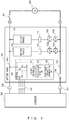
- FIG. 1 is a diagram that illustrates an example of an abnormality diagnostic device according to the present embodiment.
- a battery pack 100 includes a current sensor 110 that detects a charge current and a discharge current that flow through a battery module 101, an on/off controller 107 that performs an on/off control on MOSFETs 102a and 102b and a charge relay 104, a start-of-charge instruction unit 108 that transmits, to a charger 200 that charges the battery module 101, an instruction signal to start a charging operation, and a short circuit abnormality diagnostic unit 109 that determines, on the basis of an output signal of the current sensor 110, whether a charge current is flowing through the MOSFET 102a due to the charging operation of the charger 200, so as to diagnose a short circuit abnormality in the MOSFET 102a on the basis of a result of the determination, or that determines, on the basis of an output signal of the current sensor 110, whether a discharge
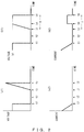
- FIG. 2 illustrates charge voltage waveforms and charge current waveforms when performing a diagnosis of the MOSFET 102a that causes a charge current to flow in.
- (a1) and (a2) of FIG. 2 respectively represent waveforms of an output voltage and a charge current of the charger 200 when the MOSFET 102a is in a normal state (without fusion).
- (b1) and (b2) of FIG. 2 respectively represent waveforms of an output voltage and a charge current of the charger 200 when there exists a short circuit abnormality in the MOSFET 102a (with fusion).
- the charging is completed at time t1, the MOSFET 102a is turned off at time t2, and then an instruction is issued to the charger 200 to start a charging operation at time t3, so as to cause the charger 200 to output a charge voltage.
- the charger 200 stops the charging operation at time t6 at which a certain period of time T has elapsed since time t3. It is determined, on the basis of a result of a detection performed by the current sensor 110, whether a charge current is flowing through the MOSFET 102a during the certain period of time T from time t3 to time t6, and it is determined that there exists a short circuit abnormality (fusion) when a charge current has flowed, and that there does not exist a short circuit abnormality (without fusion) when a charge current has not flowed.
- fusion short circuit abnormality
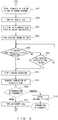
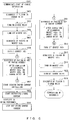
- FIG. 3 illustrates an operational flow for diagnosing a short circuit abnormality (fusion) in the MOSFET 102a by use of a charge current.
- an operation with a thick-lined border is an operation in the charger 200
- an operation with a thin-lined border is an operation in the battery pack 100.
- Step S301 When starting a diagnosis of a short circuit abnormality (fusion) by use of a charge current in a state in which the battery pack 100 is connected to the charger 200 and the charge relay 104 is on (Step S301), the on/off controller 107 of the battery pack 100 controls the MOSFET 102a that causes a charge current to flow in to be off (Step S302).
- the start-of-charge instruction unit 108 of the battery pack 100 sets a start-of-diagnosis flag that indicates that a diagnosis of a short circuit abnormality in the MOSFET 102a is started, and instructs the charger 200 to charge the battery pack 100 at a predetermined charge current rate for a certain period of time to diagnose a short circuit abnormality in the MOSFET 102a (Step S303).
- the charger 200 When receiving, from a control unit 105 of the battery pack 100, an instruction signal to start charging at the predetermined current rate for diagnosing a short circuit abnormality, the charger 200 starts applying a charge voltage to feed lines 103a and 103b of the battery pack 100 such that the battery pack 100 is charged at the predetermined current rate (Step S304).
- the charger 200 gradually increases a charge voltage to be applied while monitoring a charge current, such that the battery pack 100 is charged at the predetermined current rate described above, and monitors whether the charge voltage reaches a predetermined threshold and an overvoltage protection circuit operates (Step S305).
- Step S305 When the overvoltage protection circuit operates (YES in Step S305), the charger 200 stops outputting the charge voltage to stop the charging operation (Step S307) . On the other hand, when the overvoltage protection circuit does not operate (NO in Step S305), the charger 200 monitors whether a certain period of time has elapsed since the charging was started (Step S306) .
- Step S306 When the certain period of time has not elapsed since the charging was started (NO in Step S306), the process returns to the operation of Step S305 for the charger 200. On the other hand, when the certain period of time has elapsed since the charging was started (YES in Step S306), the charger 200 stops outputting the charge voltage to stop the charging operation (Step S307).
- the charger 200 transmits, to the battery pack 100, a completion-of-diagnosis flag that reports that the charging has been stopped (Step S308) .
- the short circuit abnormality diagnostic unit 109 of the battery pack 100 determines whether there exists a short circuit abnormality (fusion) in the MOSFET 102a by determining whether a charge current is flowing (Step S309) .
- the short circuit abnormality diagnostic unit 109 of the battery pack 100 monitors whether a charge current is flowing through the battery module 101 using the current sensor 110, and stores a result of the monitoring. In the determination of abnormality in Step S309, it is determined, on the basis of a result of the monitoring, that there exists a short circuit abnormality (fusion) in the MOSFET 102a when the fact that a charge current has flowed is stored.
- Step S309 When it is determined in Step S309 that there exists a short circuit abnormality (fusion), the short circuit abnormality diagnostic unit 109 of the battery pack 100 sets an abnormality flag reporting the short circuit abnormality (fusion) in the MOSFET 102a so as to report it to a user (Step S310), and terminates an operation for diagnosing a short circuit abnormality (fusion) .
- Step S310 when the fact that a charge current has flowed is not stored, it is determined that the MOSFET 102a is in a normal state (without fusion).
- Step S311 When the MOSFET 102a is determined to be in a normal state (without fusion) in Step S309, the on/off controller 107 turns on the MOSFET 102a (Step S311).
- Step S311 When the diagnosis of a short circuit abnormality (fusion) in the MOSFET 102a that is performed by use of a charge current is terminated, all of the MOSFETs 102a and 102b and the charge relay 104 are terminated in an on state. Before or after this diagnosis, a diagnosis of a short circuit abnormality (fusion) in the MOSFETs 102b or the charge relay 104 is appropriately performed.
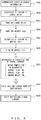
- FIG. 4 is a first operational flow for diagnosing a short circuit abnormality in each switch element by use of a charge current and a discharge current.
- Step S401 a diagnosis of a short circuit abnormality (fusion) in the MOSFET 102a by use of a charge current is performed (Step S402).
- the diagnosis in Step S402 is the diagnosis performed on the MOSFET 102a in Steps S301 to S311 described in FIG. 3 .
- the diagnosis is completed, all of the MOSFETs 102a and 102b and the charge relay 104 are in an on state.
- the on/off controller 107 of the battery pack 100 turns off the MOSFET 102b (Step S403), a transistor in the discharging circuit 106 is turned on, and the short circuit abnormality diagnostic unit 109 diagnoses a short circuit abnormality (fusion) in the MOSFET 102b (Step S404) .
- the short circuit abnormality diagnostic unit 109 determines whether there exists a short circuit abnormality (fusion) in the MOSFET 102b by determining whether a discharge current is flowing through the discharging circuit 106 (Step S405) . In the determination of abnormality in Step S405, it is determined that there exists a short circuit abnormality (fusion) in the MOSFET 102b when it is determined that a discharge current has flowed.
- Step S405 When it is determined in Step S405 that there exists an abnormality, the short circuit abnormality diagnostic unit 109 sets an abnormality flag reporting the short circuit abnormality (fusion) in the MOSFET 102b so as to report it to the user (Step S410), and terminates an operation for diagnosing an abnormality.
- Step S405 when it is determined that a discharge current has not flowed and the MOSFET 102b is determined to be in a normal state (without fusion) in Step S405, the on/off controller 107 turns on the MOSFET 102b (Step S406) and turns off the charge relay 104 (Step S407). Then, the transistor in the discharging circuit 106 is turned on, and the short circuit abnormality diagnostic unit 109 diagnoses a short circuit abnormality (fusion) in the charge relay 104 (Step S408) .
- the short circuit abnormality diagnostic unit 109 determines whether there exists a short circuit abnormality (fusion) in the charge relay 104 by determining whether a discharge current is flowing through the discharging circuit 106 (Step S409). In the determination of abnormality in Step S409, it is determined that there exists a short circuit abnormality (fusion) in the charge relay 104 when it is determined that a discharge current has flowed.
- the short circuit abnormality diagnostic unit 109 sets an abnormality flag reporting the short circuit abnormality (fusion) in the charge relay 104 so as to report it to the user (Step S410), and terminates an operation for diagnosing a short circuit abnormality (fusion).
- Step S409 that a discharge current has not flowed and the charge relay 104 is determined to be in a normal state, an operation for diagnosing a short circuit abnormality (fusion) is terminated.
- a diagnosis of a short circuit abnormality (fusion) in the first MOSFET 102a is performed in a state in which the first MOSFET 102a is off, and the first MOSFET 102a is turned on after the diagnosis
- a diagnosis of a short circuit abnormality (fusion) in the second MOSFET 102b is performed in a state in which the second MOSFET 102b is off, and the second MOSFET 102b is turned on after the diagnosis
- a diagnosis of a short circuit abnormality (fusion) in the charge relay 104 is performed in a state in which the charge relay 104 is off.
- a diagnostic operation is completed in a state in which the first and second MOSFETs 102a and 102b are on and the charge relay 104 is off when the diagnoses of a short circuit abnormality (fusion) in the first and second MOSFETs 102a and 102b and in the charge relay 104 are completed.
- This is a state in which the battery pack 100 can be immediately used for supplying power to a load 300.
- the number of on/off switching controls for diagnosing a short circuit abnormality (fusion) in each of the switch elements is minimal, which results in efficiently diagnosing a short circuit abnormality (fusion) in these switch elements.
- Step S402 may be performed next after "TURN ON MOSFET 102b" of Step S406 that is performed when the diagnosis of the second MOSFET 102b is completed, and before “TURN OFF CHARGE RELAY" of Step S407 that is performed before the diagnosis of the charge relay 104 is started.
- a diagnosis is only performed after the charging of the battery pack 100 is completed. If a diagnosis is only performed after the charging of the battery pack 100 is completed, there is a possibility that a short circuit abnormality (fusion) in each switch element will not be detected when the charging is not completed in a normal way.
- fusion short circuit abnormality
- a diagnosis of a short circuit abnormality (fusion) in each switch element is only performed after the charging of the battery pack 100 is completed, when a short circuit abnormality (fusion) occurs in any switch element, for example while a vehicle equipped with the battery pack 100 after being charged is moving, a next charging is performed without the short circuit abnormality (fusion) being detected when the charging is started, and the short circuit abnormality (fusion) is first detected after the next charging is completed.
- the first MOSFET 102a cannot be turned off due to the occurrence of a short circuit abnormality (fusion) when an abnormality occurs during the charging and the first MOSFET 102a needs to be turned off.
- a diagnosis is performed before the charging of the battery pack 100 is started.
- the problem described above can be solved by performing the second operational flow.
- the control unit 105 in the battery pack 100 communicates start-of-charge information with the charger 200 (Step S501).
- Step S502 the control unit 105 performs, on the charge relay 104 in an off state, a diagnosis of a short circuit abnormality (fusion) by use of a discharge current by a method similar to Step S408 in FIG. 4 (Step S502) .
- a short circuit abnormality (fusion) is detected as a result of the diagnosis in Step S502
- an abnormality flag is set and reported to the user as in Step S410, and the operation of the diagnosis of an abnormality is terminated (not shown).
- the charge relay 104 is turned on after the diagnosis is completed (Step S503).
- Step S504 the second MOSFET 102b is turned off (Step S504), and a diagnosis of a short circuit abnormality (fusion) in the second MOSFET 102b is performed by use of a discharge current by a method similar to Step S404 in FIG. 4 (Step S505).
- Step S505 a diagnosis of a short circuit abnormality (fusion) in the second MOSFET 102b is performed by use of a discharge current by a method similar to Step S404 in FIG. 4
- Step S505 a diagnosis of a short circuit abnormality (fusion) in the second MOSFET 102b is performed by use of a discharge current by a method similar to Step S404 in FIG. 4
- Step S505 an abnormality flag is set and reported to the user in a similar way, and the operation of the diagnosis of an abnormality is terminated (not shown) .
- Step S506 the diagnosis of an abnormality is completed.
- Step S507 a diagnosis of a short circuit abnormality (fusion) in the MOSFET 102a is performed by use of a charge current (Step S507) .
- the diagnosis in Step S507 is the diagnosis performed on the MOSFET 102a in Steps S301 to S311 described in FIG. 3 .
- the control unit 105 immediately starts issuing a charge-current instruction to the charger 200 (Step S508) .
- the charger 200 starts outputting a charge current to the battery pack 100 (Step S509).
- the diagnosis of a short circuit abnormality (fusion) before the charging is started is performed by the procedures in the second operational flow described above, the number of on/off switching controls of the first and second MOSFET 102a and 102b and the charge relay 104 is minimal, which results in efficiently diagnosing a short circuit abnormality (fusion) in these switch elements.
- Step S507 may be performed between "TURN ON CHARGE RELAY" of Step S503 and "TURN OFF MOSFET 102b" of Step S504.
- the diagnosis of a short circuit abnormality (fusion) according to the second operational flow described above is only performed before the charging of the battery pack 100 is started, and it is possible to diagnose, before the charging is started, a short circuit abnormality (fusion) that has occurred while a vehicle equipped with the battery pack 100 is moving, but it is not possible to detect a short circuit abnormality (fusion) that occurs during the charging before a next charging is started.
- a diagnosis of a short circuit abnormality (fusion) in each switch element is performed before the charging of the battery pack 100 is started and after the charging is completed. This permits solving of the problem.
- diagnoses of a short circuit abnormality (fusion) in the first and second MOSFETs 102a and 102b and the charge relay 104 are performed in Steps S601 to S609 by procedures similar to Steps S501 to S509 illustrated in FIG. 5 .
- the battery pack 100 starts to be charged by the charger 200 (Step S609), and when the charging is completed and the output of the charge current from the charger 200 is stopped (Step S610), then a diagnosis of a short circuit abnormality (fusion) after the charging is completed is performed.
- Step S611 to S616 As a diagnosis of a short circuit abnormality (fusion) after the charging is completed, a diagnosis of a short circuit abnormality (fusion) in each switch element is performed in Steps S611 to S616 by procedures similar to Steps S402 to S410 illustrated in FIG. 4 .
- Step S613 When a short circuit abnormality (fusion) is detected as a result of the diagnosis of the second MOSFET 102b in Step S613, an abnormality flag is set and reported to the user as in Step S410 in FIG. 4 , and the operation of the diagnosis of an abnormality is terminated (not shown) .
- the second MOSFET 102b is turned on after the diagnosis is completed (Step S613) .
- Step S616 when a short circuit abnormality (fusion) is detected as a result of the diagnosis of the charge relay 104 in Step S616, an abnormality flag is also set and reported to the user as in Step S410 in FIG. 4 , and the operation of the diagnosis of an abnormality is terminated (not shown) .
- Step S410 the diagnosis of an abnormality
- the order of performing the diagnosis of the first MOSFET 102a and the diagnosis of the second MOSFET 102b also may be changed in the third operational flow, but if a diagnosis of each switch element is performed in the order of the third operational flow, the number of on/off switching controls of each of the switch elements for performing a diagnosis is minimal, which results in efficiently diagnosing a short circuit abnormality (fusion) in these switch elements.
- the on/off controls of the first and second MOSFETs 102a and 102b may be performed by a battery monitoring unit (not shown) in each battery module 101 instead of the on/off controller 107 in the control unit 105 common to each battery module 101.
- start-of-charge instruction unit 108 and the short circuit abnormality diagnostic unit 109 may be included in the battery monitoring unit. Furthermore, the determination of whether a charge current is flowing may be performed by the charger 200 instead of the battery pack 100, and a diagnosis of an abnormality may be performed by the charger 200. Moreover, the charge relay 104 is not limited to a mechanical relay, and various types of switches may be applicable to it.
Description
- The present invention relates to an abnormality diagnostic device and an abnormality diagnostic method for a MOSFET (metal-oxide-semiconductor field-effect transistor) switch element included in a rechargeable battery pack, in particular, for diagnosing a short circuit abnormality (fusion) that is a state in which a MOSFET switch element remains on (short circuited) even if the MOSFET switch element is controlled to be off.
-
FIG. 7 illustrates an example of a battery pack used for, for example, an electric vehicle that is driven by a rechargeable battery. Abattery pack 100 includes one ormore battery modules 101, and thebattery module 101 includes one or more rechargeable batteries, a sensor that monitors states of the batteries, and a battery monitoring unit (not shown). - The
battery module 101 is connected to acharger 200 through positive andnegative feed lines charge relay 104, and a charger-side connector 201, and is charged by thecharger 200 . Further, thebattery module 101 is disconnected from thecharger 200 after the charging is completed, and supplies current to aload 300 of, for example, a motor through thefeed lines main switch 301. - In order to protect against an abnormality due to, for example, overcharging or overdischarging, for each
battery module 101, first and secondMOSFET switch elements feed lines battery modules 101. -
FIG. 7 illustrates an exemplary configuration in which the first and secondMOSFET switch elements negative feed line 103b, but the first and secondMOSFET switch elements positive feed line 103a. However, in order to simplify the description, the exemplary configuration in which the first and secondMOSFET switch elements negative feed line 103b will be described below, but it is also operable with an exemplary configuration in which they are provided on the side of thepositive feed line 103a. - A holding current flowing through the first and second
MOSFET switch elements MOSFET switch elements - Further, a charge current and a discharge current each flow through the
battery module 101 in opposite directions, so the first and secondMOSFET switch elements - The
first MOSFET 102a causes a charge current to flow into thebattery module 101 when it is on. When thefirst MOSFET 102a is turned on, a charge current flows into thebattery module 101 through a parasitic diode of thesecond MOSFET 102b, regardless of whether thesecond MOSFET 102b is on or off. - On the other hand, when the
first MOSFET 102a is turned off, a charge current is not allowed to flow into thebattery module 101, regardless of whether thesecond MOSFET 102b is on or off, because the direction of a parasitic diode of thefirst MOSFET 102a is opposite to that of the charge current. - Further, the
second MOSFET 102b causes a discharge current to flow out of thebattery module 101 when it is on. When thesecond MOSFET 102b is turned on, a discharge current flows out of thebattery module 101 through the parasitic diode of thefirst MOSFET 102a, regardless of whether thefirst MOSFET 102a is on or off. - On the other hand, when the
second MOSFET 102b is turned off, a discharge current is not allowed to flow out of thebattery module 101, regardless of whether thefirst MOSFET 102a is on or off, because the direction of the parasitic diode of thesecond MOSFET 102b is opposite to that of the discharge current. - In switch elements such as the first and
second MOSFET charge relay 104, there may occur a short circuit abnormality (fusion) in which a switch element remains in a short-circuited (on) state even if it is controlled to be off such that a current path is interrupted, so a frequent diagnosis of a short circuit abnormality (fusion) is required to be performed on these switch elements. - In order to diagnose a short circuit abnormality (fusion) in the
charge relay 104, for example, adischarging circuit 106 that is constituted of, for example, a transistor switch and resistance is provided in acontrol unit 105 in thebattery pack 100, and thedischarging circuit 106 is connected such that a closed circuit is formed in the order of "battery module 101→positive feed line 103a→discharging circuit 106→charge relay 104→negative feed line 103b→second MOSFET 102b→first MOSFET 102a→battery module 101". - Then, an on/off
controller 107 in thecontrol unit 105 determines whether a discharge current is flowing through thedischarging circuit 106 in a state in which thecharge relay 104 is off and thesecond MOSFET 102b is on. It is determined that a short circuit abnormality (fusion) has occurred in thecharge relay 104 when it is determined that a discharge current has flowed through thedischarging circuit 106, and it is determined that a short circuit abnormality (fusion) has not occurred in thecharge relay 104 when it is determined that a discharge current has not flowed. - Further, a short circuit abnormality (fusion) in the
second MOSFET 102b is diagnosed by use of thedischarging circuit 106 described above. For the diagnosis of a short circuit abnormality (fusion) in thesecond MOSFET 102b, the on/offcontroller 107 in thecontrol unit 105 determines whether a discharge current is flowing through thedischarging circuit 106 in a state in which thecharge relay 104 is on and thesecond MOSFET 102b is off. - It is determined that a short circuit abnormality (fusion) has occurred in the
second MOSFET 102b when it is determined that a discharge current has flowed through thedischarging circuit 106, and it is determined that a short circuit abnormality (fusion) has not occurred in thesecond MOSFET 102b when it is determined that a discharge current has not flowed. -
Patent Document 1 below discloses a method for diagnosing a short circuit abnormality (fusion) in a relay that is turned on when charging is allowed to be performed, the method including controlling the relay to be off when the diagnosis is performed, measuring voltage on one of the contact sides of the relay and voltage on the other contact side of the relay, and diagnosing fusion in the relay on the basis of these voltages. - Patent Document 1: Japanese Laid-open Patent Publication No.
2011-109872 - As described above, it is possible to diagnose a short circuit abnormality (fusion) in the
charge relay 104 and thesecond MOSFET 102b in thebattery pack 100 by determining whether a discharge current is flowing through thedischarging circuit 106 included in thebattery pack 100, wherein thesecond MOSFET 102b is a switch element that causes a discharge current to flow out. - However, it is not possible to diagnose a short circuit abnormality (fusion) in the
first MOSFET 102a by use of, for example, thedischarging circuit 106 included in the battery pack, wherein thefirst MOSFET 102a is a switch element that is another switch element connected to thebattery module 101 and that causes a charge current to flow in. The reason is that, even if thefirst MOSFET 102a is controlled to be off in a state in which thecharge relay 104 and thesecond MOSFET 102b are on, a discharge current flows into thedischarging circuit 106 through the parasitic diode of thefirst MOSFET 102a, regardless of whether there exists a short circuit abnormality (fusion). - In light of the problem described above, an object of the present invention is to provide an abnormality diagnostic device and method for diagnosing an abnormality in a MOSFET switch element, the abnormality diagnostic device and method permitting a diagnosis of the occurrence of a short circuit abnormality (fusion) in a
first MOSFET 102a that is connected to thebattery module 101 in thebattery pack 100 and that causes a charge current to flow in. - An abnormality diagnostic device for diagnosing an abnormality in a MOSFET switch element according to an aspect of the present invention includes a current sensor detecting current that flows through a battery module, and a control unit that turns off a MOSFET switch element that causes a charge current to flow into the battery module, transmits, to a charger that charges the battery module, an instruction signal to start a charging operation, and determines, on the basis of an output signal of the current sensor, whether current is flowing through the MOSFET switch element due to the charging operation of the charger, so as to diagnose a short circuit abnormality in the MOSFET switch element on the basis of a result of the determination.
- Further, in a battery pack in which a first MOSFET switch element that is the MOSFET switch element that causes the charge current to flow into and a second MOSFET switch element that is a MOSFET switch element that causes a discharge current to flow out of the battery module are connected to the battery module in series, the control unit diagnoses a short circuit abnormality in the first MOSFET switch element after the charging of the battery module performed by the charger is completed and turns off the second MOSFET switch element after the diagnosis, or before the diagnosis and after the charging is completed, and determines whether a discharge current is flowing through the second MOSFET switch element, so as to diagnose a short circuit abnormality in the second MOSFET switch element.
- Furthermore, in the battery pack in which a charge relay is further provided in a current path through which a charge current flows from the charger to the battery module, the control unit diagnoses, after the charging of the battery module performed by the charger is completed, a short circuit abnormality in the first MOSFET switch element and a short circuit abnormality in the second MOSFET switch element in a state in which the charge relay is on, turns off, after that, the charge relay in a state in which the first MOSFET switch element and the second MOSFET switch element are on, and determines whether a discharge current is flowing through the charge relay, so as to diagnose a short circuit abnormality in the charge relay.
- Moreover, in a battery pack in which a first MOSFET switch element that is the MOSFET switch element that causes a charge current to flow into and a second MOSFET switch element that is a MOSFET switch element that causes a discharge current to flow out of the battery module are connected to the battery module in series, the control unit diagnoses a short circuit abnormality in the first MOSFET switch element before the charging of the battery module performed by the charger is started and turns off the second MOSFET switch element before the diagnosis, or after the diagnosis and before the charging is started, and determines whether a discharge current is flowing through the second MOSFET switch element, so as to diagnose a short circuit abnormality in the second MOSFET switch element.
- Further, in the battery pack in which a charge relay is further provided in a current path through which a charge current flows from the charger to the battery module, the control unit determines, before the charging of the battery module performed by the charger is started, whether a discharge current is flowing through the charge relay in a state in which the charge relay is off, so as to diagnose a short circuit abnormality in the charge relay, and diagnoses, after that, a short circuit abnormality in the first MOSFET switch element and a short circuit abnormality in the second MOSFET switch element in a state in which the charge relay is on.
- According to embodiments of the present invention, it is possible to diagnose a short circuit abnormality (fusion) in a MOSFET that is connected to a battery module and that causes a charge current to flow in without an increase in cost, by causing a charger that charges a battery module in the battery pack to supply a charging current and by determining whether there exists a charge current that is flowing at that time.
- Further, if, after charging is completed, a diagnosis of a short circuit abnormality (fusion) in a first MOSFET switch element and a second MOSFET switch element that are connected to a battery module is performed, and then a diagnosis of a short circuit abnormality (fusion) in a charge relay is performed, the number of on/off switching controls of each of the switch elements for performing a diagnosis is minimal, which results in efficiently diagnosing a short circuit abnormality (fusion) in these switch elements.
- Furthermore, if, before charging is started, a diagnosis of a short circuit abnormality (fusion) in a charge relay is performed, and then a diagnosis of a short circuit abnormality (fusion) in a first MOSFET switch element and a second MOSFET switch element that are connected to a battery module is performed, the number of on/off switching controls of each of the switch elements for performing a diagnosis is minimal, which results in efficiently diagnosing a short circuit abnormality (fusion) in these switch elements.
-
-
FIG. 1 is a diagram that illustrates an example of an abnormality diagnostic device that diagnoses a short circuit abnormality in a switch element including a MOSFET that causes a charge current to flow in; -
FIG. 2 illustrates charge voltage waveforms and charge current waveforms when performing a diagnosis of the MOSFET that causes a charge current to flow in; -
FIG. 3 illustrates a flowchart of a MOSFET diagnosis by use of a charge current; -
FIG. 4 is a first flowchart for performing a diagnosis of each switch element by use of a charge current and a discharge current; -
FIG. 5 is a second flowchart for performing a diagnosis of each switch element by use of a charge current and a discharge current; -
FIG. 6 is a third flowchart for performing a diagnosis of each switch element by use of a charge current and a discharge current; and -
FIG. 7 illustrates an example of a battery pack used for diagnosing a short circuit abnormality in a MOSFET that causes a discharge current to flow out and a short circuit abnormality in a charge relay. - Embodiments of the present invention will now be described with reference to the drawings.
FIG. 1 is a diagram that illustrates an example of an abnormality diagnostic device according to the present embodiment. In the present embodiment, abattery pack 100 includes acurrent sensor 110 that detects a charge current and a discharge current that flow through abattery module 101, an on/offcontroller 107 that performs an on/off control onMOSFETs charge relay 104, a start-of-charge instruction unit 108 that transmits, to acharger 200 that charges thebattery module 101, an instruction signal to start a charging operation, and a short circuit abnormalitydiagnostic unit 109 that determines, on the basis of an output signal of thecurrent sensor 110, whether a charge current is flowing through theMOSFET 102a due to the charging operation of thecharger 200, so as to diagnose a short circuit abnormality in theMOSFET 102a on the basis of a result of the determination, or that determines, on the basis of an output signal of thecurrent sensor 110, whether a discharge current is flowing through theMOSFET 102b or thecharge relay 104 by a discharging operation of adischarging circuit 106, so as to diagnose a short circuit abnormality in theMOSFET 102b or thecharge relay 104 on the basis of a result of the determination. - An operation of the abnormality diagnostic device according to the present embodiment will be described with reference to
FIGS. 2 to 6 .FIG. 2 illustrates charge voltage waveforms and charge current waveforms when performing a diagnosis of theMOSFET 102a that causes a charge current to flow in. (a1) and (a2) ofFIG. 2 respectively represent waveforms of an output voltage and a charge current of thecharger 200 when theMOSFET 102a is in a normal state (without fusion). (b1) and (b2) ofFIG. 2 respectively represent waveforms of an output voltage and a charge current of thecharger 200 when there exists a short circuit abnormality in theMOSFET 102a (with fusion). - When the
battery pack 100 is charged by thecharger 200, as illustrated inFIG. 2 , the charging is completed at time t1, theMOSFET 102a is turned off at time t2, and then an instruction is issued to thecharger 200 to start a charging operation at time t3, so as to cause thecharger 200 to output a charge voltage. - When the
MOSFET 102a is in a normal state (without fusion), a charge current does not flow as indicated in (a2) ofFIG. 2 , so thecharger 200 increases an output voltage as indicated in (a1) ofFIG. 2 such that a predetermined charge current flows. As a result, an overvoltage protection circuit of thecharger 200 operates at time t5, and stops the charging operation. - On the other hand, when there exists a short circuit abnormality in the
MOSFET 102a (with fusion), an instruction is issued to thecharger 200 to start a charging operation at time t3, so as to cause thecharger 200 to output a charge voltage, a charge current starts flowing through theMOSFET 102a at time t4 at which the charge voltage has reached a battery voltage V1, as indicated in (b2) ofFIG. 2 , and the output voltage of thecharger 200 does not increase only up to the battery voltage V1 as illustrated in (b1) ofFIG. 2 , with the result that the overvoltage protection circuit does not operate. - The
charger 200 stops the charging operation at time t6 at which a certain period of time T has elapsed since time t3. It is determined, on the basis of a result of a detection performed by thecurrent sensor 110, whether a charge current is flowing through theMOSFET 102a during the certain period of time T from time t3 to time t6, and it is determined that there exists a short circuit abnormality (fusion) when a charge current has flowed, and that there does not exist a short circuit abnormality (without fusion) when a charge current has not flowed. -
FIG. 3 illustrates an operational flow for diagnosing a short circuit abnormality (fusion) in theMOSFET 102a by use of a charge current. InFIG. 3 , an operation with a thick-lined border is an operation in thecharger 200, and an operation with a thin-lined border is an operation in thebattery pack 100. - When starting a diagnosis of a short circuit abnormality (fusion) by use of a charge current in a state in which the
battery pack 100 is connected to thecharger 200 and thecharge relay 104 is on (Step S301), the on/offcontroller 107 of thebattery pack 100 controls theMOSFET 102a that causes a charge current to flow in to be off (Step S302). - Next, the start-of-
charge instruction unit 108 of thebattery pack 100 sets a start-of-diagnosis flag that indicates that a diagnosis of a short circuit abnormality in theMOSFET 102a is started, and instructs thecharger 200 to charge thebattery pack 100 at a predetermined charge current rate for a certain period of time to diagnose a short circuit abnormality in theMOSFET 102a (Step S303). - When receiving, from a
control unit 105 of thebattery pack 100, an instruction signal to start charging at the predetermined current rate for diagnosing a short circuit abnormality, thecharger 200 starts applying a charge voltage to feedlines battery pack 100 such that thebattery pack 100 is charged at the predetermined current rate (Step S304). - The
charger 200 gradually increases a charge voltage to be applied while monitoring a charge current, such that thebattery pack 100 is charged at the predetermined current rate described above, and monitors whether the charge voltage reaches a predetermined threshold and an overvoltage protection circuit operates (Step S305). - When the overvoltage protection circuit operates (YES in Step S305), the
charger 200 stops outputting the charge voltage to stop the charging operation (Step S307) . On the other hand, when the overvoltage protection circuit does not operate (NO in Step S305), thecharger 200 monitors whether a certain period of time has elapsed since the charging was started (Step S306) . - When the certain period of time has not elapsed since the charging was started (NO in Step S306), the process returns to the operation of Step S305 for the
charger 200. On the other hand, when the certain period of time has elapsed since the charging was started (YES in Step S306), thecharger 200 stops outputting the charge voltage to stop the charging operation (Step S307). - After stopping the charging operation, the
charger 200 transmits, to thebattery pack 100, a completion-of-diagnosis flag that reports that the charging has been stopped (Step S308) . When receiving the completion-of-diagnosis flag, the short circuit abnormalitydiagnostic unit 109 of thebattery pack 100 determines whether there exists a short circuit abnormality (fusion) in theMOSFET 102a by determining whether a charge current is flowing (Step S309) . - From when the start-of-diagnosis flag is set in Step S303 described above until the completion-of-diagnosis flag is received from the
charger 200, the short circuit abnormalitydiagnostic unit 109 of thebattery pack 100 monitors whether a charge current is flowing through thebattery module 101 using thecurrent sensor 110, and stores a result of the monitoring. In the determination of abnormality in Step S309, it is determined, on the basis of a result of the monitoring, that there exists a short circuit abnormality (fusion) in theMOSFET 102a when the fact that a charge current has flowed is stored. - When it is determined in Step S309 that there exists a short circuit abnormality (fusion), the short circuit abnormality
diagnostic unit 109 of thebattery pack 100 sets an abnormality flag reporting the short circuit abnormality (fusion) in theMOSFET 102a so as to report it to a user (Step S310), and terminates an operation for diagnosing a short circuit abnormality (fusion) . On the other hand, when the fact that a charge current has flowed is not stored, it is determined that theMOSFET 102a is in a normal state (without fusion). - When the
MOSFET 102a is determined to be in a normal state (without fusion) in Step S309, the on/offcontroller 107 turns on theMOSFET 102a (Step S311). When the diagnosis of a short circuit abnormality (fusion) in theMOSFET 102a that is performed by use of a charge current is terminated, all of theMOSFETs charge relay 104 are terminated in an on state. Before or after this diagnosis, a diagnosis of a short circuit abnormality (fusion) in theMOSFETs 102b or thecharge relay 104 is appropriately performed. - A series of operational flows for diagnosing a short circuit abnormality (fusion) in each switch element such as the
MOSFETs charge relay 104 will be described below with reference toFIGS. 4 to 6 .FIG. 4 is a first operational flow for diagnosing a short circuit abnormality in each switch element by use of a charge current and a discharge current. - In the first operational flow, after the charging of the
battery pack 100 is completed, a diagnosis is performed on the first andsecond MOSFETs charge relay 104. Thebattery pack 100 is connected to thecharger 200 to be charged, and after the charging performed by thecharger 200 is completed and the charging is stopped (Step S401), a diagnosis of a short circuit abnormality (fusion) in theMOSFET 102a by use of a charge current is performed (Step S402). - The diagnosis in Step S402 is the diagnosis performed on the
MOSFET 102a in Steps S301 to S311 described inFIG. 3 . When the diagnosis is completed, all of theMOSFETs charge relay 104 are in an on state. - Next, the on/off
controller 107 of thebattery pack 100 turns off theMOSFET 102b (Step S403), a transistor in the dischargingcircuit 106 is turned on, and the short circuit abnormalitydiagnostic unit 109 diagnoses a short circuit abnormality (fusion) in theMOSFET 102b (Step S404) . - The short circuit abnormality
diagnostic unit 109 determines whether there exists a short circuit abnormality (fusion) in theMOSFET 102b by determining whether a discharge current is flowing through the discharging circuit 106 (Step S405) . In the determination of abnormality in Step S405, it is determined that there exists a short circuit abnormality (fusion) in theMOSFET 102b when it is determined that a discharge current has flowed. - When it is determined in Step S405 that there exists an abnormality, the short circuit abnormality
diagnostic unit 109 sets an abnormality flag reporting the short circuit abnormality (fusion) in theMOSFET 102b so as to report it to the user (Step S410), and terminates an operation for diagnosing an abnormality. - On the other hand, when it is determined that a discharge current has not flowed and the
MOSFET 102b is determined to be in a normal state (without fusion) in Step S405, the on/offcontroller 107 turns on theMOSFET 102b (Step S406) and turns off the charge relay 104 (Step S407). Then, the transistor in the dischargingcircuit 106 is turned on, and the short circuit abnormalitydiagnostic unit 109 diagnoses a short circuit abnormality (fusion) in the charge relay 104 (Step S408) . - The short circuit abnormality
diagnostic unit 109 determines whether there exists a short circuit abnormality (fusion) in thecharge relay 104 by determining whether a discharge current is flowing through the discharging circuit 106 (Step S409). In the determination of abnormality in Step S409, it is determined that there exists a short circuit abnormality (fusion) in thecharge relay 104 when it is determined that a discharge current has flowed. - When in it determined in Step S409 that there exists an abnormality, the short circuit abnormality
diagnostic unit 109 sets an abnormality flag reporting the short circuit abnormality (fusion) in thecharge relay 104 so as to report it to the user (Step S410), and terminates an operation for diagnosing a short circuit abnormality (fusion). When it is determined in Step S409 that a discharge current has not flowed and thecharge relay 104 is determined to be in a normal state, an operation for diagnosing a short circuit abnormality (fusion) is terminated. - In the first operational flow, after the charging of the
battery module 101 is completed, in a state in which thecharge relay 104 remains on, (1) first, a diagnosis of a short circuit abnormality (fusion) in thefirst MOSFET 102a is performed in a state in which thefirst MOSFET 102a is off, and thefirst MOSFET 102a is turned on after the diagnosis, and (2) next, a diagnosis of a short circuit abnormality (fusion) in thesecond MOSFET 102b is performed in a state in which thesecond MOSFET 102b is off, and thesecond MOSFET 102b is turned on after the diagnosis, and then, (3) finally, a diagnosis of a short circuit abnormality (fusion) in thecharge relay 104 is performed in a state in which thecharge relay 104 is off. - If a diagnosis is performed using these procedures, a diagnostic operation is completed in a state in which the first and
second MOSFETs charge relay 104 is off when the diagnoses of a short circuit abnormality (fusion) in the first andsecond MOSFETs charge relay 104 are completed. This is a state in which thebattery pack 100 can be immediately used for supplying power to aload 300. - Thus, when diagnosing a short circuit abnormality (fusion) in each switch element such as the first and
second MOSFETs charge relay 104 after the charging performed by thecharger 200 is completed, the number of on/off switching controls for diagnosing a short circuit abnormality (fusion) in each of the switch elements is minimal, which results in efficiently diagnosing a short circuit abnormality (fusion) in these switch elements. - In the first operational flow, even if the order of performing the diagnoses on the
first MOSFET 102a and thesecond MOSFET 102b is changed, the number of on/off switching controls for diagnosing a short circuit abnormality (fusion) in each switch element remains unchanged. - Thus, "DIAGNOSIS OF FUSION BY USE OF CHARGE CURRENT (the diagnosis of the
first MOSFET 102a)" of Step S402 may be performed next after "TURN ON MOSFET 102b" of Step S406 that is performed when the diagnosis of thesecond MOSFET 102b is completed, and before "TURN OFF CHARGE RELAY" of Step S407 that is performed before the diagnosis of thecharge relay 104 is started. - In the first operational flow illustrated in
FIG. 4 described above, a diagnosis is only performed after the charging of thebattery pack 100 is completed. If a diagnosis is only performed after the charging of thebattery pack 100 is completed, there is a possibility that a short circuit abnormality (fusion) in each switch element will not be detected when the charging is not completed in a normal way. - As an example, when the charging is stopped by pulling out a charger-
side connector 201, with the result that thecharger 200 and thebattery pack 100 are separated from each other, or when the charging is stopped by the user pushing an emergency stop button down, with the result that a power circuit of thecharger 200 powers down, the charging of thebattery pack 100 is not completed in a normal way. - Further, if a diagnosis of a short circuit abnormality (fusion) in each switch element is only performed after the charging of the
battery pack 100 is completed, when a short circuit abnormality (fusion) occurs in any switch element, for example while a vehicle equipped with thebattery pack 100 after being charged is moving, a next charging is performed without the short circuit abnormality (fusion) being detected when the charging is started, and the short circuit abnormality (fusion) is first detected after the next charging is completed. - Thus, there may occur a problem in which, after the charging of the
battery pack 100 is started, thefirst MOSFET 102a cannot be turned off due to the occurrence of a short circuit abnormality (fusion) when an abnormality occurs during the charging and thefirst MOSFET 102a needs to be turned off. - Thus, as illustrated in
FIG. 5 as a second operational flow, a diagnosis is performed before the charging of thebattery pack 100 is started. The problem described above can be solved by performing the second operational flow. In the second operational flow, when thebattery pack 100 is connected to thecharger 200, thecontrol unit 105 in thebattery pack 100 communicates start-of-charge information with the charger 200 (Step S501). - Next, the
control unit 105 performs, on thecharge relay 104 in an off state, a diagnosis of a short circuit abnormality (fusion) by use of a discharge current by a method similar to Step S408 inFIG. 4 (Step S502) . When a short circuit abnormality (fusion) is detected as a result of the diagnosis in Step S502, an abnormality flag is set and reported to the user as in Step S410, and the operation of the diagnosis of an abnormality is terminated (not shown). When a short circuit abnormality (fusion) is not detected, thecharge relay 104 is turned on after the diagnosis is completed (Step S503). - Next, the
second MOSFET 102b is turned off (Step S504), and a diagnosis of a short circuit abnormality (fusion) in thesecond MOSFET 102b is performed by use of a discharge current by a method similar to Step S404 inFIG. 4 (Step S505). When a short circuit abnormality (fusion) is detected as a result of the diagnosis in Step S505, an abnormality flag is set and reported to the user in a similar way, and the operation of the diagnosis of an abnormality is terminated (not shown) . When a short circuit abnormality (fusion) is not detected, thesecond MOSFET 102b is turned on after the diagnosis is completed (Step S506) . - Then, a diagnosis of a short circuit abnormality (fusion) in the
MOSFET 102a is performed by use of a charge current (Step S507) . The diagnosis in Step S507 is the diagnosis performed on theMOSFET 102a in Steps S301 to S311 described inFIG. 3 . - When the diagnosis is completed, all of the
MOSFETs charge relay 104 are in an on state and in a state in which charging can be started immediately. Thus, thecontrol unit 105 immediately starts issuing a charge-current instruction to the charger 200 (Step S508) . In response to a signal of the charge-current instruction, thecharger 200 starts outputting a charge current to the battery pack 100 (Step S509). - If the diagnosis of a short circuit abnormality (fusion) before the charging is started is performed by the procedures in the second operational flow described above, the number of on/off switching controls of the first and
second MOSFET charge relay 104 is minimal, which results in efficiently diagnosing a short circuit abnormality (fusion) in these switch elements. - In the second operational flow described above, even if the order of performing the diagnosis of the
first MOSFET 102a in Step S507 and the diagnosis of thesecond MOSFET 102b in Steps S504 to S506 is changed, the number of on/off switching controls for diagnosing a short circuit abnormality (fusion) in each switch element remains unchanged. Thus, the diagnosis in Step S507 may be performed between "TURN ON CHARGE RELAY" of Step S503 and "TURN OFF MOSFET 102b" of Step S504. - The diagnosis of a short circuit abnormality (fusion) according to the second operational flow described above is only performed before the charging of the
battery pack 100 is started, and it is possible to diagnose, before the charging is started, a short circuit abnormality (fusion) that has occurred while a vehicle equipped with thebattery pack 100 is moving, but it is not possible to detect a short circuit abnormality (fusion) that occurs during the charging before a next charging is started. - Thus, as illustrated in
FIG. 6 as a third operational flow, a diagnosis of a short circuit abnormality (fusion) in each switch element is performed before the charging of thebattery pack 100 is started and after the charging is completed. This permits solving of the problem. - In the third operational flow, as a diagnosis before the charging is started, diagnoses of a short circuit abnormality (fusion) in the first and
second MOSFETs charge relay 104 are performed in Steps S601 to S609 by procedures similar to Steps S501 to S509 illustrated inFIG. 5 . - After the diagnosis before the charging is started is completed, the
battery pack 100 starts to be charged by the charger 200 (Step S609), and when the charging is completed and the output of the charge current from thecharger 200 is stopped (Step S610), then a diagnosis of a short circuit abnormality (fusion) after the charging is completed is performed. - As a diagnosis of a short circuit abnormality (fusion) after the charging is completed, a diagnosis of a short circuit abnormality (fusion) in each switch element is performed in Steps S611 to S616 by procedures similar to Steps S402 to S410 illustrated in
FIG. 4 . When a short circuit abnormality (fusion) is detected as a result of the diagnosis of thesecond MOSFET 102b in Step S613, an abnormality flag is set and reported to the user as in Step S410 inFIG. 4 , and the operation of the diagnosis of an abnormality is terminated (not shown) . When a short circuit abnormality (fusion) is not detected, thesecond MOSFET 102b is turned on after the diagnosis is completed (Step S613) . - Further, when a short circuit abnormality (fusion) is detected as a result of the diagnosis of the
charge relay 104 in Step S616, an abnormality flag is also set and reported to the user as in Step S410 inFIG. 4 , and the operation of the diagnosis of an abnormality is terminated (not shown) . When a short circuit abnormality (fusion) is not detected, the operation of the diagnosis of an abnormality is terminated at this point. - The order of performing the diagnosis of the
first MOSFET 102a and the diagnosis of thesecond MOSFET 102b also may be changed in the third operational flow, but if a diagnosis of each switch element is performed in the order of the third operational flow, the number of on/off switching controls of each of the switch elements for performing a diagnosis is minimal, which results in efficiently diagnosing a short circuit abnormality (fusion) in these switch elements. - The embodiments of the present invention have been described above, but the present invention is not limited to the embodiments described above, and various modifications and alterations may be made thereto without departing from the spirit and scope of the invention.
- For example, the on/off controls of the first and
second MOSFETs battery module 101 instead of the on/offcontroller 107 in thecontrol unit 105 common to eachbattery module 101. - Further, the start-of-
charge instruction unit 108 and the short circuit abnormalitydiagnostic unit 109 may be included in the battery monitoring unit. Furthermore, the determination of whether a charge current is flowing may be performed by thecharger 200 instead of thebattery pack 100, and a diagnosis of an abnormality may be performed by thecharger 200. Moreover, thecharge relay 104 is not limited to a mechanical relay, and various types of switches may be applicable to it. -
- 100
- battery pack
- 101
- battery module
- 102a
- first MOSFET switch element
- 102b
- second MOSFET switch element
- 103a
- positive feed line
- 103b
- negative feed line
- 104
- charge relay
- 105
- control unit (control ECU)
- 106
- discharging circuit
- 107
- on/off controller
- 108
- start-of-charge instruction unit
- 109
- short circuit abnormality diagnostic unit
- 110
- current sensor
- 200
- charger
- 201
- a charger-side connector
- 300
- load
- 301
- main switch
Claims (4)
- An abnormality diagnostic device for diagnosing an abnormality in a MOSFET switch element (102), the abnormality diagnostic device comprising:a current sensor(110) detecting current that flows through a battery module(101);a first MOSFET switch element (102a) that causes a charge current to flow into the battery module (101) and is connected to the battery module(101) in series;a second MOSFET switch element(102b) that causes a discharge current to flow out of the battery module (101) and is connected to the first MOSFET switch element (102a) and the battery module(101) in series;a charge relay(104) that is provided in a current path through which a charge current flows from a charger (200) to the battery module(101); anda control unit(105)that turns off, after the charging of the battery module(101) performed by the charger(200) is completed, the first MOSFET switch element (102a) in a state in which the charge relay(104) is on, transmits, to the charger(200), an instruction signal to start a charging operation, and determines, on the basis of an output signal of the current sensor, whether current is flowing through the first MOSFET switch element(102a) due to the charging operation of the charger(200), so as to diagnose a short circuit abnormality in the first MOSFET switch element (102a) on the basis of a result of the determination;that turns off, after the charging is completed, the second MOSFET switch element (102b) in a state in which the charge relay(104) is on, and determines whether a discharge current is flowing through the second MOSFET switch element(102b), so as to diagnose a short circuit abnormality in the second MOSFET switch element(102b); andthat turns off, after the diagnoses of a short circuit abnormality in the first MOSFET switch element(102a) and a short circuit abnormality in the second MOSFET switch element(102b) are completed, the charge relay(104) in a state in which the first MOSFET switch element(102a) and the second MOSFET switch element(102b) are on, and determines whether a discharge current is flowing through the charge relay (104), so as to diagnose a short circuit abnormality in the charge relay(104) .
- An abnormality diagnostic device for diagnosing an abnormality in a MOSFET switch element(102), the abnormality diagnostic device comprising:a current sensor(110) detecting current that flows through a battery module(101);a first MOSFET switch element (102a) that causes a charge current to flow into the battery module (101) and is connected to the battery module(101) in series;a second MOSFET switch element(102b) that causes a discharge current to flow out of the battery module(101) and is connected to the first MOSFET switch element(102a) and the battery module(101) in series;a charge relay(104) that is provided in a current path through which a charge current flows from a charger (200) to the battery module(101); anda control unit(105)that determines, before the charging of the battery module(101) performed by the charger(200) is started, whether a discharge current is flowing through the charge relay(104) in a state in which the charge relay(104) is off, so as to diagnose a short circuit abnormality in the charge relay (104) ;that turns off, after the diagnosis of a short circuit abnormality in the charge relay(104) is completed and before the charging is started, the first MOSFET switch element (102a) in a state in which the charge relay (104) is on, transmits, to the charger (200), an instruction signal to start a charging operation, determines, on the basis of an output signal of the current sensor(110), whether current is flowing through the first MOSFET switch element(102a) due to the charging operation of the charger(200), so as to diagnose a short circuit abnormality in the first MOSFET switch element(102a) on the basis of a result of the determination, and turns on, after the diagnosis, the first MOSFET switch element(102a) when a short circuit abnormality has not been detected; andthat turns off, after the diagnosis of a short circuit abnormality in the charge relay(104) is completed and before the charging is started, the second MOSFET switch element (102b) in a state in which the charge relay (104) is on, determines whether a discharge current is flowing through the second MOSFET switch element (102b), so as to diagnose a short circuit abnormality in the second MOSFET switch element (102b), and turns on, after the diagnosis, the second MOSFET switch element(102b) when a short circuit abnormality has not been detected.
- An abnormality diagnostic method for diagnosing an abnormality in a MOSFET switch element(102), wherein the diagnosis is performed with respect to a battery pack(100) including a current sensor(110) detecting current that flows through a battery module(101), a first MOSFET switch element(102a) that causes a charge current to flow into the battery module (101) and is connected to the battery module (101) in series, a second MOSFET switch element (102b) that causes a discharge current to flow out of the battery module(101) and is connected to the first MOSFET switch element (102a) and the battery module (101) in series, and a charge relay (104) that is provided in a current path through which a charge current flows from a charger (200) to the battery module(101), the abnormality diagnostic method comprising:turning off, after the charging of the battery module(101) performed by the charger(200) is completed, the first MOSFET switch element (102a) in a state in which the charge relay(104) is on, transmitting, to the charger(200), an instruction signal to start a charging operation, and determining, on the basis of an output signal of the current sensor(110), whether current is flowing through the first MOSFET switch element(102a) due to the charging operation of the charger(200), so as to diagnose a short circuit abnormality in the first MOSFET switch element(102a) on the basis of a result of the determination;turning off, after the charging is completed, the second MOSFET switch element(102b) in a state in which the charge relay(104) is on, and determining whether a discharge current is flowing through the second MOSFET switch element(102b), so as to diagnose a short circuit abnormality in the second MOSFET switch element(102b); andturning off, after the diagnoses of a short circuit abnormality in the first MOSFET switch element (102a) and a short circuit abnormality in the second MOSFET switch element (102b) are completed, the charge relay(104) in a state in which the first MOSFET switch element (102a) and the second MOSFET switch element(102b) are on, and determining whether a discharge current is flowing through the charge relay(104), so as to diagnose a short circuit abnormality in the charge relay(104) .
- An abnormality diagnostic method for diagnosing an abnormality in a MOSFET switch element(102), wherein the diagnosis is performed with respect to a battery pack(100) including a current sensor(110) detecting current that flows through a battery module(101), a first MOSFET switch element(102a) that causes a charge current to flow into the battery module (101) and is connected to the battery module (101) in series, a second MOSFET switch element (102b) that causes a discharge current to flow out of the battery module (101) and is connected to the first MOSFET switch element (102a) and the battery module (101) in series, and a charge relay (104) that is provided in a current path through which a charge current flows from a charger(200) to the battery module(101), the abnormality diagnostic method comprising:determining, before the charging of the battery module(101) performed by the charger(200) is started, whether a discharge current is flowing through the charge relay(104) in a state in which the charge relay (104) is off, so as to diagnose a short circuit abnormality in the charge relay (104) ;turning off, after the diagnosis of a short circuit abnormality in the charge relay (104) is completed and before the charging is started, the first MOSFET switch element (102a) in a state in which the charge relay (104) is on, transmitting, to the charger (200), an instruction signal to start a charging operation, determining, on the basis of an output signal of the current sensor (110), whether current is flowing through the first MOSFET switch element (102a) due to the charging operation of the charger (200), so as to diagnose a short circuit abnormality in the first MOSFET switch element (102a) on the basis of a result of the determination, and turning on, after the diagnosis, the first MOSFET switch element (102a) when a short circuit abnormality has not been detected; andturning off, after the diagnosis of a short circuit abnormality in the charge relay (104) is completed and before the charging is started, the second MOSFET switch element (102b) in a state in which the charge relay (104) is on, determining whether a discharge current is flowing through the second MOSFET switch element (102b), so as to diagnose a short circuit abnormality in the second MOSFET switch element (102b), and turning on, after the diagnosis, the second MOSFET switch element (102b) when a short circuit abnormality has not been detected.
Applications Claiming Priority (3)
| Application Number | Priority Date | Filing Date | Title |
|---|---|---|---|
| JP2013193594 | 2013-09-19 | ||
| JP2014053305A JP5652562B1 (en) | 2013-09-19 | 2014-03-17 | MOSFET switch element abnormality diagnosis apparatus and method |
| PCT/JP2014/067341 WO2015040923A1 (en) | 2013-09-19 | 2014-06-30 | Anomaly detector in mosfet switching element and method for detecting anomaly |
Publications (3)
| Publication Number | Publication Date |
|---|---|
| EP3048693A1 EP3048693A1 (en) | 2016-07-27 |
| EP3048693A4 EP3048693A4 (en) | 2016-10-05 |
| EP3048693B1 true EP3048693B1 (en) | 2018-01-17 |
Family
ID=52339817
Family Applications (1)
| Application Number | Title | Priority Date | Filing Date |
|---|---|---|---|
| EP14846577.6A Active EP3048693B1 (en) | 2013-09-19 | 2014-06-30 | Anomaly detector in mosfet switching element and method for detecting anomaly |
Country Status (4)
| Country | Link |
|---|---|
| US (1) | US9766292B2 (en) |
| EP (1) | EP3048693B1 (en) |
| JP (1) | JP5652562B1 (en) |
| WO (1) | WO2015040923A1 (en) |
Families Citing this family (24)
| Publication number | Priority date | Publication date | Assignee | Title |
|---|---|---|---|---|
| DE102014202198A1 (en) * | 2014-02-06 | 2015-08-06 | Robert Bosch Gmbh | Method for checking an automatic parking brake system |
| US10033213B2 (en) | 2014-09-30 | 2018-07-24 | Johnson Controls Technology Company | Short circuit wake-up system and method for automotive battery while in key-off position |
| CN104578307B (en) * | 2015-01-23 | 2017-01-18 | 浙江大学 | Structure of fault-tolerant lithium-ion battery pack and fault detection method |
| CN104953557A (en) * | 2015-07-01 | 2015-09-30 | 珠海银隆电器有限公司 | Protection device for power battery contactor of electric automobile and control method of protection device |
| JP2017030464A (en) * | 2015-07-30 | 2017-02-09 | 株式会社オートネットワーク技術研究所 | Power supply control device and power supply control system |
| US10103556B2 (en) * | 2015-11-17 | 2018-10-16 | Motorola Solutions, Inc. | Load side method of blocking charger voltage from a battery load |
| US10283982B2 (en) * | 2016-01-27 | 2019-05-07 | Gm Global Technology Operations Llc. | Voltage disconnect architecture |
| EP3336956B1 (en) * | 2016-12-14 | 2023-08-30 | Robert Bosch GmbH | Method for monitoring a discharge device of a battery |
| US10883895B2 (en) * | 2016-12-15 | 2021-01-05 | Mitsubishi Electric Corporation | Abnormality diagnostic device for power transmission mechanism and abnormality diagnostic method for power transmission mechanism |
| US10229873B2 (en) * | 2017-02-07 | 2019-03-12 | International Business Machines Corporation | Three plate MIM capacitor via integrity verification |
| JP6898122B2 (en) * | 2017-03-23 | 2021-07-07 | 株式会社マキタ | Charger |
| CN107170924B (en) * | 2017-04-24 | 2020-05-01 | 北京长城华冠汽车科技股份有限公司 | Battery box and electric automobile |
| TWM576750U (en) | 2017-07-25 | 2019-04-11 | 美商米沃奇電子工具公司 | Electrical composition, electric device system, battery pack, electric motor, motor assembly and electric motor assembly |
| GB2551081B (en) * | 2017-08-18 | 2018-12-19 | O2Micro Inc | Fault detection for battery management systems |
| KR102423301B1 (en) * | 2017-12-11 | 2022-07-19 | 주식회사 엘지에너지솔루션 | Apparatus and method for preventing short |
| KR102364572B1 (en) * | 2017-12-14 | 2022-02-17 | 주식회사 엘지에너지솔루션 | System and method for diagnosing relay fault |
| CN108258754A (en) * | 2017-12-29 | 2018-07-06 | 惠州市蓝微新源技术有限公司 | A kind of charge and discharge quick seamless handoff system |
| KR102412313B1 (en) * | 2018-07-17 | 2022-06-22 | 주식회사 엘지에너지솔루션 | Apparatus and method for diagnosing switch |
| JP6779949B2 (en) * | 2018-09-04 | 2020-11-04 | 本田技研工業株式会社 | Power storage system and abnormality judgment method |
| CN110970962A (en) * | 2018-12-07 | 2020-04-07 | 宁德时代新能源科技股份有限公司 | Charging and discharging circuit |
| CN110347143B (en) * | 2019-08-07 | 2020-10-16 | 中国核动力研究设计院 | Nuclear safety level optimization module field drive output loop diagnosis system and method |
| CN111152659B (en) * | 2019-12-25 | 2021-09-10 | 浙江合众新能源汽车有限公司 | Battery pack high-voltage topological structure and relay adhesion detection method based on structure |
| CN112834918B (en) * | 2020-12-21 | 2023-05-05 | 深圳供电局有限公司 | Switch fault detection method and switch fault detection device |
| US11929698B2 (en) * | 2021-03-23 | 2024-03-12 | Snap-On Incorporated | Short circuit protection for a BLDC motor |
Family Cites Families (8)
| Publication number | Priority date | Publication date | Assignee | Title |
|---|---|---|---|---|
| JP3433000B2 (en) * | 1996-05-29 | 2003-08-04 | 三洋電機株式会社 | Charge method for pulse charging of assembled batteries |
| JP2004343850A (en) * | 2003-05-14 | 2004-12-02 | Nippon Telegr & Teleph Corp <Ntt> | Charging system |
| US7642750B2 (en) * | 2005-10-04 | 2010-01-05 | O2Micro International Limited | Battery charge/discharge control circuit |
| JP2007215309A (en) | 2006-02-08 | 2007-08-23 | Sanyo Electric Co Ltd | Battery pack control method |
| JP4591560B2 (en) * | 2008-06-24 | 2010-12-01 | ソニー株式会社 | Battery pack and control method |
| JP5087064B2 (en) | 2009-11-20 | 2012-11-28 | パナソニック株式会社 | Power supply control device |
| JP5733786B2 (en) * | 2010-11-02 | 2015-06-10 | Necエナジーデバイス株式会社 | Secondary battery system |
| JP5414818B2 (en) * | 2012-02-23 | 2014-02-12 | 三菱電機株式会社 | Electric vehicle power converter |
-
2014
- 2014-03-17 JP JP2014053305A patent/JP5652562B1/en active Active
- 2014-06-30 WO PCT/JP2014/067341 patent/WO2015040923A1/en active Application Filing
- 2014-06-30 US US15/021,582 patent/US9766292B2/en active Active
- 2014-06-30 EP EP14846577.6A patent/EP3048693B1/en active Active
Non-Patent Citations (1)
| Title |
|---|
| None * |
Also Published As
| Publication number | Publication date |
|---|---|
| EP3048693A4 (en) | 2016-10-05 |
| WO2015040923A1 (en) | 2015-03-26 |
| JP2015084631A (en) | 2015-04-30 |
| JP5652562B1 (en) | 2015-01-14 |
| US9766292B2 (en) | 2017-09-19 |
| US20160231382A1 (en) | 2016-08-11 |
| EP3048693A1 (en) | 2016-07-27 |
Similar Documents
| Publication | Publication Date | Title |
|---|---|---|
| EP3048693B1 (en) | Anomaly detector in mosfet switching element and method for detecting anomaly | |
| US9225182B2 (en) | Charge controller with protective function and battery pack | |
| JP6614443B2 (en) | Battery device, vehicle, battery management program, and battery device management method | |
| US20190271743A1 (en) | Power supply protective device, power supply device and switch failure diagnosing method | |
| US10284193B2 (en) | Semiconductor switch control device | |
| EP1897661B1 (en) | Power tool | |
| KR101614202B1 (en) | Current measurement relay apparatus | |
| US9966639B2 (en) | Battery monitoring device | |
| US20160156258A1 (en) | Power source control device and method for detecting relay abnormality | |
| US9843184B2 (en) | Voltage conversion apparatus | |
| JP2015077933A (en) | Vehicle power supply system | |
| US10177560B2 (en) | Battery monitoring device | |
| KR20160041495A (en) | Apparatus and method for diagnosing MOSFET of MOSFET switch operating apparatus | |
| CN111699605B (en) | Battery control device | |
| KR20190072276A (en) | Apparatus and method for diagnosing a watchdog timer | |
| US10377239B2 (en) | Auxiliary battery status determination device and auxiliary battery status determination method | |
| EP3683099A1 (en) | Door latch power supply device, door latch power supply system, and vehicle using same | |
| EP2998200B1 (en) | Electric power steering device | |
| US11368015B2 (en) | Process for testing the operability of a circuit breaker device | |
| WO2016060009A1 (en) | Relay control device and relay control method | |
| JP5638795B2 (en) | Battery state monitoring circuit and battery device | |
| JP6825678B2 (en) | vehicle | |
| JP6323162B2 (en) | Battery monitoring device | |
| JPWO2013118401A1 (en) | Battery control device | |
| CN103997070A (en) | Voltage monitoring apparatus of assembled battery |
Legal Events
| Date | Code | Title | Description |
|---|---|---|---|
| PUAI | Public reference made under article 153(3) epc to a published international application that has entered the european phase |
Free format text: ORIGINAL CODE: 0009012 |
|
| 17P | Request for examination filed |
Effective date: 20160311 |
|
| AK | Designated contracting states |
Kind code of ref document: A1 Designated state(s): AL AT BE BG CH CY CZ DE DK EE ES FI FR GB GR HR HU IE IS IT LI LT LU LV MC MK MT NL NO PL PT RO RS SE SI SK SM TR |
|
| AX | Request for extension of the european patent |
Extension state: BA ME |
|
| A4 | Supplementary search report drawn up and despatched |
Effective date: 20160901 |
|
| RIC1 | Information provided on ipc code assigned before grant |
Ipc: H01M 10/48 20060101ALI20160826BHEP Ipc: H02H 7/18 20060101ALI20160826BHEP Ipc: G01R 31/02 20060101ALI20160826BHEP Ipc: H02H 3/087 20060101ALI20160826BHEP Ipc: H03K 17/00 20060101ALI20160826BHEP Ipc: G01R 31/327 20060101ALI20160826BHEP Ipc: H03K 17/082 20060101ALI20160826BHEP Ipc: H03K 17/08 20060101ALI20160826BHEP Ipc: H02J 7/00 20060101AFI20160826BHEP |
|
| DAX | Request for extension of the european patent (deleted) | ||
| RIC1 | Information provided on ipc code assigned before grant |
Ipc: G01R 31/02 20060101ALI20170330BHEP Ipc: H02J 7/00 20060101AFI20170330BHEP Ipc: H01M 10/48 20060101ALI20170330BHEP Ipc: H03K 17/08 20060101ALI20170330BHEP Ipc: H03K 17/082 20060101ALI20170330BHEP Ipc: H02H 7/18 20060101ALI20170330BHEP Ipc: H02H 3/087 20060101ALI20170330BHEP Ipc: G01R 31/327 20060101ALI20170330BHEP Ipc: H03K 17/00 20060101ALI20170330BHEP |
|
| GRAP | Despatch of communication of intention to grant a patent |
Free format text: ORIGINAL CODE: EPIDOSNIGR1 |
|
| INTG | Intention to grant announced |
Effective date: 20170927 |
|
| GRAS | Grant fee paid |
Free format text: ORIGINAL CODE: EPIDOSNIGR3 |
|
| GRAA | (expected) grant |
Free format text: ORIGINAL CODE: 0009210 |
|
| AK | Designated contracting states |
Kind code of ref document: B1 Designated state(s): AL AT BE BG CH CY CZ DE DK EE ES FI FR GB GR HR HU IE IS IT LI LT LU LV MC MK MT NL NO PL PT RO RS SE SI SK SM TR |
|
| REG | Reference to a national code |
Ref country code: GB Ref legal event code: FG4D |
|
| REG | Reference to a national code |
Ref country code: CH Ref legal event code: EP |
|
| REG | Reference to a national code |
Ref country code: IE Ref legal event code: FG4D |
|
| REG | Reference to a national code |
Ref country code: AT Ref legal event code: REF Ref document number: 965041 Country of ref document: AT Kind code of ref document: T Effective date: 20180215 |
|
| REG | Reference to a national code |
Ref country code: DE Ref legal event code: R096 Ref document number: 602014020188 Country of ref document: DE |
|
| REG | Reference to a national code |
Ref country code: NL Ref legal event code: MP Effective date: 20180117 |
|
| REG | Reference to a national code |
Ref country code: LT Ref legal event code: MG4D |
|
| REG | Reference to a national code |
Ref country code: AT Ref legal event code: MK05 Ref document number: 965041 Country of ref document: AT Kind code of ref document: T Effective date: 20180117 |
|
| PG25 | Lapsed in a contracting state [announced via postgrant information from national office to epo] |
Ref country code: NL Free format text: LAPSE BECAUSE OF FAILURE TO SUBMIT A TRANSLATION OF THE DESCRIPTION OR TO PAY THE FEE WITHIN THE PRESCRIBED TIME-LIMIT Effective date: 20180117 |
|
| PG25 | Lapsed in a contracting state [announced via postgrant information from national office to epo] |
Ref country code: NO Free format text: LAPSE BECAUSE OF FAILURE TO SUBMIT A TRANSLATION OF THE DESCRIPTION OR TO PAY THE FEE WITHIN THE PRESCRIBED TIME-LIMIT Effective date: 20180417 Ref country code: LT Free format text: LAPSE BECAUSE OF FAILURE TO SUBMIT A TRANSLATION OF THE DESCRIPTION OR TO PAY THE FEE WITHIN THE PRESCRIBED TIME-LIMIT Effective date: 20180117 Ref country code: FI Free format text: LAPSE BECAUSE OF FAILURE TO SUBMIT A TRANSLATION OF THE DESCRIPTION OR TO PAY THE FEE WITHIN THE PRESCRIBED TIME-LIMIT Effective date: 20180117 Ref country code: CY Free format text: LAPSE BECAUSE OF FAILURE TO SUBMIT A TRANSLATION OF THE DESCRIPTION OR TO PAY THE FEE WITHIN THE PRESCRIBED TIME-LIMIT Effective date: 20180117 Ref country code: ES Free format text: LAPSE BECAUSE OF FAILURE TO SUBMIT A TRANSLATION OF THE DESCRIPTION OR TO PAY THE FEE WITHIN THE PRESCRIBED TIME-LIMIT Effective date: 20180117 Ref country code: HR Free format text: LAPSE BECAUSE OF FAILURE TO SUBMIT A TRANSLATION OF THE DESCRIPTION OR TO PAY THE FEE WITHIN THE PRESCRIBED TIME-LIMIT Effective date: 20180117 |
|
| PG25 | Lapsed in a contracting state [announced via postgrant information from national office to epo] |
Ref country code: RS Free format text: LAPSE BECAUSE OF FAILURE TO SUBMIT A TRANSLATION OF THE DESCRIPTION OR TO PAY THE FEE WITHIN THE PRESCRIBED TIME-LIMIT Effective date: 20180117 Ref country code: BG Free format text: LAPSE BECAUSE OF FAILURE TO SUBMIT A TRANSLATION OF THE DESCRIPTION OR TO PAY THE FEE WITHIN THE PRESCRIBED TIME-LIMIT Effective date: 20180417 Ref country code: AT Free format text: LAPSE BECAUSE OF FAILURE TO SUBMIT A TRANSLATION OF THE DESCRIPTION OR TO PAY THE FEE WITHIN THE PRESCRIBED TIME-LIMIT Effective date: 20180117 Ref country code: SE Free format text: LAPSE BECAUSE OF FAILURE TO SUBMIT A TRANSLATION OF THE DESCRIPTION OR TO PAY THE FEE WITHIN THE PRESCRIBED TIME-LIMIT Effective date: 20180117 Ref country code: IS Free format text: LAPSE BECAUSE OF FAILURE TO SUBMIT A TRANSLATION OF THE DESCRIPTION OR TO PAY THE FEE WITHIN THE PRESCRIBED TIME-LIMIT Effective date: 20180517 Ref country code: LV Free format text: LAPSE BECAUSE OF FAILURE TO SUBMIT A TRANSLATION OF THE DESCRIPTION OR TO PAY THE FEE WITHIN THE PRESCRIBED TIME-LIMIT Effective date: 20180117 Ref country code: GR Free format text: LAPSE BECAUSE OF FAILURE TO SUBMIT A TRANSLATION OF THE DESCRIPTION OR TO PAY THE FEE WITHIN THE PRESCRIBED TIME-LIMIT Effective date: 20180418 Ref country code: PL Free format text: LAPSE BECAUSE OF FAILURE TO SUBMIT A TRANSLATION OF THE DESCRIPTION OR TO PAY THE FEE WITHIN THE PRESCRIBED TIME-LIMIT Effective date: 20180117 |
|
| REG | Reference to a national code |
Ref country code: DE Ref legal event code: R097 Ref document number: 602014020188 Country of ref document: DE |
|
| PG25 | Lapsed in a contracting state [announced via postgrant information from national office to epo] |
Ref country code: EE Free format text: LAPSE BECAUSE OF FAILURE TO SUBMIT A TRANSLATION OF THE DESCRIPTION OR TO PAY THE FEE WITHIN THE PRESCRIBED TIME-LIMIT Effective date: 20180117 Ref country code: IT Free format text: LAPSE BECAUSE OF FAILURE TO SUBMIT A TRANSLATION OF THE DESCRIPTION OR TO PAY THE FEE WITHIN THE PRESCRIBED TIME-LIMIT Effective date: 20180117 Ref country code: RO Free format text: LAPSE BECAUSE OF FAILURE TO SUBMIT A TRANSLATION OF THE DESCRIPTION OR TO PAY THE FEE WITHIN THE PRESCRIBED TIME-LIMIT Effective date: 20180117 Ref country code: AL Free format text: LAPSE BECAUSE OF FAILURE TO SUBMIT A TRANSLATION OF THE DESCRIPTION OR TO PAY THE FEE WITHIN THE PRESCRIBED TIME-LIMIT Effective date: 20180117 |
|
| PLBE | No opposition filed within time limit |
Free format text: ORIGINAL CODE: 0009261 |
|
| STAA | Information on the status of an ep patent application or granted ep patent |
Free format text: STATUS: NO OPPOSITION FILED WITHIN TIME LIMIT |
|
| PG25 | Lapsed in a contracting state [announced via postgrant information from national office to epo] |
Ref country code: CZ Free format text: LAPSE BECAUSE OF FAILURE TO SUBMIT A TRANSLATION OF THE DESCRIPTION OR TO PAY THE FEE WITHIN THE PRESCRIBED TIME-LIMIT Effective date: 20180117 Ref country code: SK Free format text: LAPSE BECAUSE OF FAILURE TO SUBMIT A TRANSLATION OF THE DESCRIPTION OR TO PAY THE FEE WITHIN THE PRESCRIBED TIME-LIMIT Effective date: 20180117 Ref country code: SM Free format text: LAPSE BECAUSE OF FAILURE TO SUBMIT A TRANSLATION OF THE DESCRIPTION OR TO PAY THE FEE WITHIN THE PRESCRIBED TIME-LIMIT Effective date: 20180117 Ref country code: DK Free format text: LAPSE BECAUSE OF FAILURE TO SUBMIT A TRANSLATION OF THE DESCRIPTION OR TO PAY THE FEE WITHIN THE PRESCRIBED TIME-LIMIT Effective date: 20180117 |
|
| 26N | No opposition filed |
Effective date: 20181018 |
|
| REG | Reference to a national code |
Ref country code: CH Ref legal event code: PL |
|
| GBPC | Gb: european patent ceased through non-payment of renewal fee |
Effective date: 20180630 |
|
| PG25 | Lapsed in a contracting state [announced via postgrant information from national office to epo] |
Ref country code: SI Free format text: LAPSE BECAUSE OF FAILURE TO SUBMIT A TRANSLATION OF THE DESCRIPTION OR TO PAY THE FEE WITHIN THE PRESCRIBED TIME-LIMIT Effective date: 20180117 |
|
| REG | Reference to a national code |
Ref country code: BE Ref legal event code: MM Effective date: 20180630 |
|
| PG25 | Lapsed in a contracting state [announced via postgrant information from national office to epo] |
Ref country code: MC Free format text: LAPSE BECAUSE OF FAILURE TO SUBMIT A TRANSLATION OF THE DESCRIPTION OR TO PAY THE FEE WITHIN THE PRESCRIBED TIME-LIMIT Effective date: 20180117 Ref country code: LU Free format text: LAPSE BECAUSE OF NON-PAYMENT OF DUE FEES Effective date: 20180630 |
|
| REG | Reference to a national code |
Ref country code: IE Ref legal event code: MM4A |
|
| PG25 | Lapsed in a contracting state [announced via postgrant information from national office to epo] |
Ref country code: FR Free format text: LAPSE BECAUSE OF NON-PAYMENT OF DUE FEES Effective date: 20180630 Ref country code: GB Free format text: LAPSE BECAUSE OF NON-PAYMENT OF DUE FEES Effective date: 20180630 Ref country code: IE Free format text: LAPSE BECAUSE OF NON-PAYMENT OF DUE FEES Effective date: 20180630 Ref country code: LI Free format text: LAPSE BECAUSE OF NON-PAYMENT OF DUE FEES Effective date: 20180630 Ref country code: CH Free format text: LAPSE BECAUSE OF NON-PAYMENT OF DUE FEES Effective date: 20180630 |
|
| PG25 | Lapsed in a contracting state [announced via postgrant information from national office to epo] |
Ref country code: BE Free format text: LAPSE BECAUSE OF NON-PAYMENT OF DUE FEES Effective date: 20180630 |
|
| PG25 | Lapsed in a contracting state [announced via postgrant information from national office to epo] |
Ref country code: MT Free format text: LAPSE BECAUSE OF NON-PAYMENT OF DUE FEES Effective date: 20180630 |
|
| PG25 | Lapsed in a contracting state [announced via postgrant information from national office to epo] |
Ref country code: TR Free format text: LAPSE BECAUSE OF FAILURE TO SUBMIT A TRANSLATION OF THE DESCRIPTION OR TO PAY THE FEE WITHIN THE PRESCRIBED TIME-LIMIT Effective date: 20180117 |
|
| PG25 | Lapsed in a contracting state [announced via postgrant information from national office to epo] |
Ref country code: PT Free format text: LAPSE BECAUSE OF FAILURE TO SUBMIT A TRANSLATION OF THE DESCRIPTION OR TO PAY THE FEE WITHIN THE PRESCRIBED TIME-LIMIT Effective date: 20180117 |
|
| PG25 | Lapsed in a contracting state [announced via postgrant information from national office to epo] |
Ref country code: HU Free format text: LAPSE BECAUSE OF FAILURE TO SUBMIT A TRANSLATION OF THE DESCRIPTION OR TO PAY THE FEE WITHIN THE PRESCRIBED TIME-LIMIT; INVALID AB INITIO Effective date: 20140630 Ref country code: MK Free format text: LAPSE BECAUSE OF NON-PAYMENT OF DUE FEES Effective date: 20180117 |
|
| P01 | Opt-out of the competence of the unified patent court (upc) registered |
Effective date: 20230519 |
|
| PGFP | Annual fee paid to national office [announced via postgrant information from national office to epo] |
Ref country code: DE Payment date: 20230502 Year of fee payment: 10 |