EP3048628A1 - Bypass switch - Google Patents
Bypass switch Download PDFInfo
- Publication number
- EP3048628A1 EP3048628A1 EP14873245.6A EP14873245A EP3048628A1 EP 3048628 A1 EP3048628 A1 EP 3048628A1 EP 14873245 A EP14873245 A EP 14873245A EP 3048628 A1 EP3048628 A1 EP 3048628A1
- Authority
- EP
- European Patent Office
- Prior art keywords
- contact
- latch
- closing
- end side
- insulating rod
- Prior art date
- Legal status (The legal status is an assumption and is not a legal conclusion. Google has not performed a legal analysis and makes no representation as to the accuracy of the status listed.)
- Granted
Links
Images

Classifications
-
- H—ELECTRICITY
- H01—ELECTRIC ELEMENTS
- H01H—ELECTRIC SWITCHES; RELAYS; SELECTORS; EMERGENCY PROTECTIVE DEVICES
- H01H3/00—Mechanisms for operating contacts
- H01H3/32—Driving mechanisms, i.e. for transmitting driving force to the contacts
- H01H3/38—Driving mechanisms, i.e. for transmitting driving force to the contacts using spring or other flexible shaft coupling
-
- H—ELECTRICITY
- H01—ELECTRIC ELEMENTS
- H01H—ELECTRIC SWITCHES; RELAYS; SELECTORS; EMERGENCY PROTECTIVE DEVICES
- H01H3/00—Mechanisms for operating contacts
- H01H3/22—Power arrangements internal to the switch for operating the driving mechanism
- H01H3/30—Power arrangements internal to the switch for operating the driving mechanism using spring motor
- H01H3/3031—Means for locking the spring in a charged state
-
- H—ELECTRICITY
- H01—ELECTRIC ELEMENTS
- H01H—ELECTRIC SWITCHES; RELAYS; SELECTORS; EMERGENCY PROTECTIVE DEVICES
- H01H33/00—High-tension or heavy-current switches with arc-extinguishing or arc-preventing means
- H01H33/60—Switches wherein the means for extinguishing or preventing the arc do not include separate means for obtaining or increasing flow of arc-extinguishing fluid
- H01H33/66—Vacuum switches
- H01H33/666—Operating arrangements
-
- H—ELECTRICITY
- H01—ELECTRIC ELEMENTS
- H01H—ELECTRIC SWITCHES; RELAYS; SELECTORS; EMERGENCY PROTECTIVE DEVICES
- H01H79/00—Protective switches in which excess current causes the closing of contacts, e.g. for short-circuiting the apparatus to be protected
-
- H—ELECTRICITY
- H01—ELECTRIC ELEMENTS
- H01H—ELECTRIC SWITCHES; RELAYS; SELECTORS; EMERGENCY PROTECTIVE DEVICES
- H01H9/00—Details of switching devices, not covered by groups H01H1/00 - H01H7/00
- H01H9/20—Interlocking, locking, or latching mechanisms
-
- H—ELECTRICITY
- H01—ELECTRIC ELEMENTS
- H01H—ELECTRIC SWITCHES; RELAYS; SELECTORS; EMERGENCY PROTECTIVE DEVICES
- H01H2235/00—Springs
- H01H2235/01—Spiral spring
-
- H—ELECTRICITY
- H01—ELECTRIC ELEMENTS
- H01H—ELECTRIC SWITCHES; RELAYS; SELECTORS; EMERGENCY PROTECTIVE DEVICES
- H01H3/00—Mechanisms for operating contacts
- H01H3/22—Power arrangements internal to the switch for operating the driving mechanism
- H01H3/30—Power arrangements internal to the switch for operating the driving mechanism using spring motor
- H01H3/3052—Linear spring motors
-
- H—ELECTRICITY
- H01—ELECTRIC ELEMENTS
- H01H—ELECTRIC SWITCHES; RELAYS; SELECTORS; EMERGENCY PROTECTIVE DEVICES
- H01H3/00—Mechanisms for operating contacts
- H01H3/32—Driving mechanisms, i.e. for transmitting driving force to the contacts
- H01H3/46—Driving mechanisms, i.e. for transmitting driving force to the contacts using rod or lever linkage, e.g. toggle
Definitions
- the present invention relates to a bypass switch used in power electronics equipment or the like.
- a voltage converter is needed, and in the voltage converter, a semiconductor such as an IGBT is used as a switch for current.
- a bypass switch is needed for protecting a diode or preventing breakdown of the system upon failure of the IGBT.
- the bypass switch is to protect the diode or prevent breakdown of the system by short-circuiting and closing the bypass switch itself upon failure of the IGBT. Therefore, the bypass switch needs to operate before the diode fails.
- the time until the diode fails is very short, it is important, as a required function of the bypass switch, that the time until closing since reception of a signal is as short as possible.
- the bypass switch used in the power electronics equipment is required to allow high voltage or large current to be applied by means of short-circuit closing. Therefore, a vacuum valve may be employed for a switch main unit.
- An example of conventional operation mechanism units for the vacuum valve includes: an open/close rod connected to a movable contact of the vacuum valve; an open/close block which is provided to the open/close rod, movable in the axial direction, and engaged via a predetermined play; and a disk-like open/close spring which is displaced in accordance with movement of the open/close block and has a greater turnover load to the open/close block than a vacuum-self-closing force of the vacuum valve, wherein the open/close block is moved in the axial direction by an operation lever, whereby the open/close spring acts in a contact-opening or contact-closing direction to perform contact opening or contact closing (for example, see Patent Document 1).
- Patent Document 1 Japanese Examined Patent Publication No. 59-8932 (pages 1 and 2, FIGS. 1 to 4 )
- the present invention has been made to solve the above problems, and an object thereof is to obtain a bypass switch with the closing time shortened.
- a bypass switch is a bypass switch using a vacuum valve having a fixed contact and a movable contact, the bypass switch including:
- the insulating rod connected to the movable contact, the closing spring having the closing function and the contact-pressing function, and the operation unit having the latch function to keep the contact-opened state are provided on the drive side of the vacuum valve composing the switch main unit, and these components are arranged in series along the axial direction of the vacuum valve. Therefore, a force of the closing spring can be smoothly transmitted to the movable contact, and the closing time taken to cancel the engagement of the latch and complete the closing can be shortened.
- the structure of the operation unit is simplified and the number of components in the movable part is reduced, the weight of the operation unit can be reduced. Further, since the assembly is facilitated, the assembly time can be shortened.
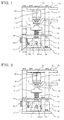
- FIG. 1 and FIG. 2 are side views of a bypass switch according to embodiment 1 of the present invention.
- FIG. 1 shows a contact-opened state
- FIG. 2 shows a contact-closed state.
- the left side is referred to as a front side.
- FIG. 1 For a switch main unit of the bypass switch, a vacuum valve is used.
- FIG. 1 and FIG. 2 the sectional views are shown in a partially broken manner so as to facilitate understanding of the internal structure.
- a vacuum valve 1 has a fixed contact 2a and a movable contact 2b provided in a vacuum chamber so as to be able to contact with each other and be separated from each other.
- the fixed contact 2a is connected to a fixed-side conductor 4a via a fixed-side electrode rod 3a
- the movable contact 2b is connected to a movable-side electrode rod 3b
- the other end of the movable-side electrode rod 3b is led out of the vacuum chamber, to be connected to an insulating rod 5.
- the movable-side electrode rod 3b is connected to a movable-side conductor 4b via a flexible conductor 6.
- a coupling metal member 7 is connected to an end of the insulating rod 5 opposite to the side connected to the movable-side electrode rod 3b, and the coupling metal member 7 is coupled with a lever 8 via a coupling pin 9.
- the fixed-side conductor 4a is fixed to a horizontal frame 10 on the upper side, the horizontal frame 10 is supported by a vertical frame 11, and a lower end side of the vertical frame 11 is fixed to a base 12.
- An intermediate horizontal frame 13 is provided at an intermediate part of the vertical frame 11, and a part below the intermediate horizontal frame 13 is an operation unit.
- a coil-like closing spring 14 is fitted to the insulating rod 5, and energizes the movable contact 2b in the contact-closing direction, between the insulating rod 5 and the intermediate horizontal frame 13.
- the closing spring 14 drives the movable contact 2b in the closing direction, and energizes the movable contact 2b to the fixed contact 2a side in the contact-closed state.
- FIG. 3 is a front sectional view as seen from an A-A direction in FIG. 1 .
- FIG. 4 is a front sectional view as seen from a B-B direction in FIG. 1 .
- a support member 15 for supporting the operation unit is fixed by a bolt.
- the support member 15 is composed of two plate-like members each having an L shape as seen from the front side, and is fixed on the base 12 such that the vertical planes of the plate-like members face each other via a predetermined interval.
- one end side of the lever 8 is rotatably supported by a lever fixation pin 16.
- a latch 17 is provided which can be engaged at an engagement part C (see FIG. 1 ) formed on the other end side of the lever 8.
- the latch 17 is rotatably provided on the support member 15.
- the latch 17 is formed by a round-bar member a part of which along the longitudinal direction is cut so as to have a semicircular cross section, and thus formed as a so-called semicircular latch. The corner of the semicircular part corresponds to the engagement part C.
- the latch is a mechanical latch.
- the coupling metal member 7 provided at the end of the insulating rod 5 is connected by the coupling pin 9 at an intermediate part between the lever fixation pin 16 serving as a pivot of the lever 8 and the engagement part on the front end side.
- a latch drive piece 18 is fixed being directed orthogonally to the axial direction of the latch 17.
- a return spring 19 formed by, for example, a coil spring is provided between the latch 17 and the support member 15. By the return spring 19, the latch 17 is energized in the counterclockwise direction as seen from the direction in FIG. 1 .
- a solenoid 20 of a direct-acting type is provided at a position opposed to the latch drive piece 18.
- the solenoid 20 is fixed on the vertical frame 11 side or the support member 15 side, although not shown.
- the latch drive piece 18 is pressed and the latch 17 is turned in the clockwise direction in FIG. 1 .
- the lever fixation pin 16 has, at one end side thereof (in the present embodiment, the right side as seen from the front side), a protrusion 16a protruding outward of the support member 15.
- the coupling pin 9 for fastening the coupling metal member 7 has, at one end side thereof (the same side as the protrusion 16a), a protrusion 9a protruding outward of the support member 15.
- a relief hole is formed at a part where the protrusion 9a penetrates through the support member 15, so that the vertical movement of the protrusion 9a is not regulated by the support member 15. The purposes of the protrusions 9a and 16a will be described later.
- the latch drive piece 18 is pressed and the latch 17 is turned in the clockwise direction.
- the closing spring 14 is released, and then the movable contact 2b together with the insulating rod 5 and the movable-side electrode rod 3b instantaneously moves to the fixed contact 2a side, to come into contact with the fixed contact 2a, whereby the movement is stopped, leading to the contact-closed state as shown in FIG. 2 .
- the closing spring 14 is set so as to contract from its natural length even in the contact-closed state. Therefore, in the contact-closed state, the contacts 2a and 2b are in contact with each other under a constant contact-pressure load. Even if the excitation of the solenoid 20 is cancelled, the contact state is kept.
- FIG. 5 is an explanation diagram for explaining the contact-opening operation.
- the contact-opening operation is manually performed using an operation handle 21.
- a hole provided at one end of the operation handle 21 is fitted to the protrusion 16a of the lever fixation pin 16, and an engagement recess formed in a side surface of the operation handle 21 is engaged with the protrusion 9a of the coupling pin 9.
- the coupling pin 9 moves downward, and along with this, the insulating rod 5 moves downward, whereby the contact pressure load is released and contact opening is started.
- the closing spring 14 provided directly under the insulating rod 5 is released by operation of the operation unit provided under the closing spring 14. Therefore, it becomes possible to perform high-speed operation after the closing operation is started, whereby the closing time can be shortened.
- the structure is simplified and the weight is reduced, as compared to the case of using a link or the case of using the disk-like spring as in Patent Document 1.
- the bypass switch of embodiment 1 is a bypass switch using a vacuum valve having a fixed contact and a movable contact, and including: an insulating rod having one end side connected to the movable contact; a closing spring having a closing function and contact-pressing function and fitted to the other end side of the insulating rod; and an operation unit having a latch function to keep a contact-opened state and connected to the other end side of the insulating rod, wherein the insulating rod, the closing spring, and the operation unit are arranged in series along the axial direction of the vacuum valve. Therefore, a force of the closing spring can be smoothly transmitted to the movable contact, and the closing time taken to cancel the engagement of the latch and complete the closing can be shortened.
- the structure of the operation unit is simplified and the number of components in the movable part is reduced, the weight of the operation unit can be reduced. Further, since the assembly is facilitated, the assembly time can be shortened.
- the operation unit includes: a lever having one end side rotatably supported by a support member, the other end side at which an engagement part is formed, and an intermediate part coupled with the other end side of the insulating rod; a latch that can be engaged with an engagement part of the lever; and a solenoid for driving the latch, wherein the contact-opened state is kept by the latch being engaged with the engagement part of the lever, and the closing spring is released to perform contact closing by the engagement being cancelled by excitation of the solenoid. Therefore, it becomes possible to keep the contact-opened state and perform quick contact-closing operation, with a simple configuration.
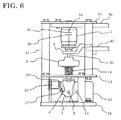
- FIG. 6 is a side view of a bypass switch according to embodiment 2. While the components corresponding to those in FIG. 1 in embodiment 1 are denoted by the same reference characters and the description thereof is omitted, a different part will be mainly described. The different part is the structure of the operation unit below the closing spring 14. In FIG. 6 , the sectional view is shown in a partially broken manner so as to facilitate understanding of the internal structure.
- the shape of the latch 17 and the shape of the latch drive piece 18 fixed thereto are the same as in embodiment 1.
- the latch 17 is located at such a position that, depending on the turn position thereof, allows the latch 17 to be engaged with the engagement part of the coupling metal member 7, and is rotatably attached to the support member 15.
- the solenoid 20 for pressing the latch drive piece 18 is fixed on the support member 15 side.
- FIG. 6 shows a contact-opened state, in which the latch 17 is turned in the counterclockwise direction by the return spring 19, to be engaged at the engagement part C, thereby keeping the contact-opened state. From this state, when the solenoid 20 is excited in response to a contact-closing command, the latch drive piece 18 is pressed to turn the latch 17 in the clockwise direction, the engagement is cancelled, and the closing spring 14 is released, whereby the contacts are closed.
- a contact-opening operation is performed by the operation handle 21 as in embodiment 1.
- the latch 17 and the solenoid 20 are provided only on one side of the coupling metal member 7. However, such components may be provided on both sides. In this case, a force is applied evenly with respect to the central axis, whereby more stable operation is achieved.
- the operation unit includes: a latch that can be engaged with an engagement part of the coupling metal member coupled with the other end side of the insulating rod; and a solenoid for driving the latch, wherein the contact-opened state is kept by the latch being engaged with the engagement part of the coupling metal member, and the closing spring is released to perform contact closing by the engagement being cancelled by excitation of the solenoid. Therefore, the structure of the operation unit is simplified, and downsizing and weight reduction of the movable part can be achieved.
Landscapes
- Driving Mechanisms And Operating Circuits Of Arc-Extinguishing High-Tension Switches (AREA)
- High-Tension Arc-Extinguishing Switches Without Spraying Means (AREA)
Abstract
Description
- The present invention relates to a bypass switch used in power electronics equipment or the like.
- In recent years, renewable energy has been increasingly introduced in an electric power field, and as a measure for system stabilization, introduction or enhancement of power electronics equipment such as a STATCOM (static synchronous compensator) is performed. In the power electronics equipment, a voltage converter is needed, and in the voltage converter, a semiconductor such as an IGBT is used as a switch for current. In the converter, a bypass switch is needed for protecting a diode or preventing breakdown of the system upon failure of the IGBT. The bypass switch is to protect the diode or prevent breakdown of the system by short-circuiting and closing the bypass switch itself upon failure of the IGBT. Therefore, the bypass switch needs to operate before the diode fails. However, since the time until the diode fails is very short, it is important, as a required function of the bypass switch, that the time until closing since reception of a signal is as short as possible.
- The bypass switch used in the power electronics equipment is required to allow high voltage or large current to be applied by means of short-circuit closing. Therefore, a vacuum valve may be employed for a switch main unit.
- An example of conventional operation mechanism units for the vacuum valve includes: an open/close rod connected to a movable contact of the vacuum valve; an open/close block which is provided to the open/close rod, movable in the axial direction, and engaged via a predetermined play; and a disk-like open/close spring which is displaced in accordance with movement of the open/close block and has a greater turnover load to the open/close block than a vacuum-self-closing force of the vacuum valve, wherein the open/close block is moved in the axial direction by an operation lever, whereby the open/close spring acts in a contact-opening or contact-closing direction to perform contact opening or contact closing (for example, see Patent Document 1).
- Patent Document 1: Japanese Examined Patent Publication No.
59-8932 pages 1 and 2,FIGS. 1 to 4 ) - In the case of using, as the bypass switch, such a vacuum valve having an operation mechanism as in
Patent Document 1, in the closing operation, the open/close block connected to the movable contact is directly driven by a drive mechanism, and there is a problem that it takes some time since the operation lever is pressed to the open/close block to start operation until the disk-like open/close spring turns over in the contact-closing direction and the contact is closed. - Instead of the disk-like open/close spring, a method in which an operation rod and an operation mechanism unit are linked via a link mechanism to perform a closing operation is also widely known. However, even in this case, it still takes a time of, for example, about several tens ms since start of the closing operation until completion thereof.
- The present invention has been made to solve the above problems, and an object thereof is to obtain a bypass switch with the closing time shortened.
- A bypass switch according to the present invention is a bypass switch using a vacuum valve having a fixed contact and a movable contact, the bypass switch including:
- an insulating rod having one end side connected to the movable contact; a closing spring having a closing function and a contact-pressing function, and fitted to another end side of the insulating rod; and an operation unit having a latch function to keep a contact-opened state, and connected to the other end side of the insulating rod, wherein the insulating rod, the closing spring, and the operation unit are arranged in series along an axial direction of the vacuum valve.
- In the bypass switch of the present invention, the insulating rod connected to the movable contact, the closing spring having the closing function and the contact-pressing function, and the operation unit having the latch function to keep the contact-opened state are provided on the drive side of the vacuum valve composing the switch main unit, and these components are arranged in series along the axial direction of the vacuum valve. Therefore, a force of the closing spring can be smoothly transmitted to the movable contact, and the closing time taken to cancel the engagement of the latch and complete the closing can be shortened.
- In addition, since the structure of the operation unit is simplified and the number of components in the movable part is reduced, the weight of the operation unit can be reduced. Further, since the assembly is facilitated, the assembly time can be shortened.
-
- [
FIG. 1] FIG. 1 is a side view showing a contact-opened state of a bypass switch according toembodiment 1 of the present invention. - [
FIG. 2] FIG. 2 is a side view showing a contact-closed state of the bypass switch according toembodiment 1 of the present invention. - [
FIG. 3] FIG. 3 is a sectional view of an operation unit as seen from an A-A direction inFIG. 1 . - [
FIG. 4] FIG. 4 is a sectional view of the operation unit as seen from a B-B direction inFIG. 1 . - [
FIG. 5] FIG. 5 is an explanation diagram for explaining a contact-opening operation of the bypass switch inFIG. 1 . - [
FIG. 6] FIG. 6 is a side view of a bypass switch according to embodiment 2 of the present invention. - Hereinafter, the description will be given based on the drawings.
FIG. 1 and FIG. 2 are side views of a bypass switch according toembodiment 1 of the present invention.FIG. 1 shows a contact-opened state, andFIG. 2 shows a contact-closed state. InFIG. 1 and FIG. 2 , for convenience sake, the left side is referred to as a front side. - For a switch main unit of the bypass switch, a vacuum valve is used. First, the entire configuration will be described with reference to
FIG. 1 . InFIG. 1 and FIG. 2 , the sectional views are shown in a partially broken manner so as to facilitate understanding of the internal structure. - A
vacuum valve 1 has a fixedcontact 2a and amovable contact 2b provided in a vacuum chamber so as to be able to contact with each other and be separated from each other. Thefixed contact 2a is connected to a fixed-side conductor 4a via a fixed-side electrode rod 3a, themovable contact 2b is connected to a movable-side electrode rod 3b, and the other end of the movable-side electrode rod 3b is led out of the vacuum chamber, to be connected to aninsulating rod 5. The movable-side electrode rod 3b is connected to a movable-side conductor 4b via aflexible conductor 6. - A
coupling metal member 7 is connected to an end of theinsulating rod 5 opposite to the side connected to the movable-side electrode rod 3b, and thecoupling metal member 7 is coupled with alever 8 via acoupling pin 9. - The fixed-
side conductor 4a is fixed to ahorizontal frame 10 on the upper side, thehorizontal frame 10 is supported by avertical frame 11, and a lower end side of thevertical frame 11 is fixed to abase 12. An intermediatehorizontal frame 13 is provided at an intermediate part of thevertical frame 11, and a part below the intermediatehorizontal frame 13 is an operation unit. - Directly under the
insulating rod 5, a coil-like closing spring 14 is fitted to theinsulating rod 5, and energizes themovable contact 2b in the contact-closing direction, between theinsulating rod 5 and the intermediatehorizontal frame 13. - The
closing spring 14 drives themovable contact 2b in the closing direction, and energizes themovable contact 2b to the fixedcontact 2a side in the contact-closed state. -
FIG. 3 is a front sectional view as seen from an A-A direction inFIG. 1 .FIG. 4 is a front sectional view as seen from a B-B direction inFIG. 1 . With reference to alsoFIG. 3 and FIG. 4 , the configuration of the operation unit will be described. - On the
base 12, asupport member 15 for supporting the operation unit is fixed by a bolt. As shown inFIG. 3 , thesupport member 15 is composed of two plate-like members each having an L shape as seen from the front side, and is fixed on thebase 12 such that the vertical planes of the plate-like members face each other via a predetermined interval. - On the back side as seen from the front side of the
support member 15, one end side of thelever 8 is rotatably supported by alever fixation pin 16. On the front side of thelever 8, alatch 17 is provided which can be engaged at an engagement part C (seeFIG. 1 ) formed on the other end side of thelever 8. Thelatch 17 is rotatably provided on thesupport member 15. Thelatch 17 is formed by a round-bar member a part of which along the longitudinal direction is cut so as to have a semicircular cross section, and thus formed as a so-called semicircular latch. The corner of the semicircular part corresponds to the engagement part C. Thus, the latch is a mechanical latch. - The
coupling metal member 7 provided at the end of theinsulating rod 5 is connected by thecoupling pin 9 at an intermediate part between thelever fixation pin 16 serving as a pivot of thelever 8 and the engagement part on the front end side. - On the
latch 17, alatch drive piece 18 is fixed being directed orthogonally to the axial direction of thelatch 17. As shown inFIG. 4 , areturn spring 19 formed by, for example, a coil spring is provided between thelatch 17 and thesupport member 15. By thereturn spring 19, thelatch 17 is energized in the counterclockwise direction as seen from the direction inFIG. 1 . - A
solenoid 20 of a direct-acting type is provided at a position opposed to thelatch drive piece 18. Thesolenoid 20 is fixed on thevertical frame 11 side or thesupport member 15 side, although not shown. By a coil of thesolenoid 20 being excited, thelatch drive piece 18 is pressed and thelatch 17 is turned in the clockwise direction inFIG. 1 . - As shown in
FIG. 3 , thelever fixation pin 16 has, at one end side thereof (in the present embodiment, the right side as seen from the front side), aprotrusion 16a protruding outward of thesupport member 15. Similarly, thecoupling pin 9 for fastening thecoupling metal member 7 has, at one end side thereof (the same side as theprotrusion 16a), aprotrusion 9a protruding outward of thesupport member 15. As shown inFIG. 1 , a relief hole is formed at a part where theprotrusion 9a penetrates through thesupport member 15, so that the vertical movement of theprotrusion 9a is not regulated by thesupport member 15. The purposes of theprotrusions - Next, operation of each part will be described. First, the closing operation of the
vacuum valve 1 will be described. - In the contact-opened state as shown in
FIG. 1 , thesolenoid 20 is not excited, thelatch 17 is energized by thereturn spring 19 so as to turn in the counterclockwise direction, and the semicircular-shapedlatch 17 and thelever 8 are engaged with each other at the engagement part C as shown inFIG. 1 , whereby thelever 8 is prevented from turning in the clockwise direction and the contact-opened state is kept. At this time, the closingspring 14 stores energy. - Here, when the
solenoid 20 is excited in response to a contact-closing command, thelatch drive piece 18 is pressed and thelatch 17 is turned in the clockwise direction. By this operation, the engagement between thelatch 17 and thelever 8 is cancelled, the closingspring 14 is released, and then themovable contact 2b together with the insulatingrod 5 and the movable-side electrode rod 3b instantaneously moves to the fixedcontact 2a side, to come into contact with the fixedcontact 2a, whereby the movement is stopped, leading to the contact-closed state as shown inFIG. 2 . The closingspring 14 is set so as to contract from its natural length even in the contact-closed state. Therefore, in the contact-closed state, thecontacts solenoid 20 is cancelled, the contact state is kept. - Next, the contact-opening operation will be described.
-
FIG. 5 is an explanation diagram for explaining the contact-opening operation. The contact-opening operation is manually performed using anoperation handle 21. As shown inFIG. 5 , a hole provided at one end of the operation handle 21 is fitted to theprotrusion 16a of thelever fixation pin 16, and an engagement recess formed in a side surface of the operation handle 21 is engaged with theprotrusion 9a of thecoupling pin 9. By pushing down the other end side of the operation handle 21 in a thick-arrow direction with a force equal to or greater than the energization force of theclosing spring 14, thecoupling pin 9 moves downward, and along with this, the insulatingrod 5 moves downward, whereby the contact pressure load is released and contact opening is started. When the operation handle 21 is further pushed down to move the engagement part of thelever 8 downward over thelatch 17 and thereby the interference is cancelled, thelatch 17 turns in the counterclockwise direction by thereturn spring 19, and thelatch 17 and thelever 8 can be engaged with each other at the engagement part C, leading to the state as shown inFIG. 1 . - Thus, the closing
spring 14 provided directly under the insulatingrod 5 is released by operation of the operation unit provided under theclosing spring 14. Therefore, it becomes possible to perform high-speed operation after the closing operation is started, whereby the closing time can be shortened. In addition, the structure is simplified and the weight is reduced, as compared to the case of using a link or the case of using the disk-like spring as inPatent Document 1. - Since a semicircular latch is employed as the latch, the engagement with the engagement part can be cancelled by slight turning of the latch, thus contributing to increase in the speed of the closing operation.
- As described above, the bypass switch of
embodiment 1 is a bypass switch using a vacuum valve having a fixed contact and a movable contact, and including: an insulating rod having one end side connected to the movable contact; a closing spring having a closing function and contact-pressing function and fitted to the other end side of the insulating rod; and an operation unit having a latch function to keep a contact-opened state and connected to the other end side of the insulating rod, wherein the insulating rod, the closing spring, and the operation unit are arranged in series along the axial direction of the vacuum valve. Therefore, a force of the closing spring can be smoothly transmitted to the movable contact, and the closing time taken to cancel the engagement of the latch and complete the closing can be shortened. - In addition, since the structure of the operation unit is simplified and the number of components in the movable part is reduced, the weight of the operation unit can be reduced. Further, since the assembly is facilitated, the assembly time can be shortened.
- The operation unit includes: a lever having one end side rotatably supported by a support member, the other end side at which an engagement part is formed, and an intermediate part coupled with the other end side of the insulating rod; a latch that can be engaged with an engagement part of the lever; and a solenoid for driving the latch, wherein the contact-opened state is kept by the latch being engaged with the engagement part of the lever, and the closing spring is released to perform contact closing by the engagement being cancelled by excitation of the solenoid. Therefore, it becomes possible to keep the contact-opened state and perform quick contact-closing operation, with a simple configuration.
-
FIG. 6 is a side view of a bypass switch according to embodiment 2. While the components corresponding to those inFIG. 1 inembodiment 1 are denoted by the same reference characters and the description thereof is omitted, a different part will be mainly described. The different part is the structure of the operation unit below the closingspring 14. InFIG. 6 , the sectional view is shown in a partially broken manner so as to facilitate understanding of the internal structure. - As shown in
FIG. 6 , in the structure of the operation unit, thelever 8 inFIG. 1 is removed, and an engagement part that can be engaged with thelatch 17 is directly provided to thecoupling metal member 7 provided at the end of the insulatingrod 5. - The shape of the
latch 17 and the shape of thelatch drive piece 18 fixed thereto are the same as inembodiment 1. Thelatch 17 is located at such a position that, depending on the turn position thereof, allows thelatch 17 to be engaged with the engagement part of thecoupling metal member 7, and is rotatably attached to thesupport member 15. Thesolenoid 20 for pressing thelatch drive piece 18 is fixed on thesupport member 15 side. -
FIG. 6 shows a contact-opened state, in which thelatch 17 is turned in the counterclockwise direction by thereturn spring 19, to be engaged at the engagement part C, thereby keeping the contact-opened state. From this state, when thesolenoid 20 is excited in response to a contact-closing command, thelatch drive piece 18 is pressed to turn thelatch 17 in the clockwise direction, the engagement is cancelled, and theclosing spring 14 is released, whereby the contacts are closed. A contact-opening operation is performed by the operation handle 21 as inembodiment 1. - By such a configuration, since the
latch 17 is directly engaged with thecoupling metal member 7, as compared toembodiment 1, thelever 8 is removed and downsizing and weight reduction of the movable part can be achieved, and further, the closing time can be shortened. - In
FIG. 6 , thelatch 17 and thesolenoid 20 are provided only on one side of thecoupling metal member 7. However, such components may be provided on both sides. In this case, a force is applied evenly with respect to the central axis, whereby more stable operation is achieved. - As described above, in the bypass switch of embodiment 2, the operation unit includes: a latch that can be engaged with an engagement part of the coupling metal member coupled with the other end side of the insulating rod; and a solenoid for driving the latch, wherein the contact-opened state is kept by the latch being engaged with the engagement part of the coupling metal member, and the closing spring is released to perform contact closing by the engagement being cancelled by excitation of the solenoid. Therefore, the structure of the operation unit is simplified, and downsizing and weight reduction of the movable part can be achieved.
- It is noted that, within the scope of the present invention, the above embodiments may be freely combined with each other, or each of the above embodiments may be modified or abbreviated as appropriate.
-
- 1
- vacuum valve
- 2a
- fixed contact
- 2b
- movable contact
- 3a
- fixed-side electrode rod
- 3b
- movable-side electrode rod
- 4a
- fixed-side conductor
- 4b
- movable-side conductor
- 5
- insulating rod
- 6
- flexible conductor
- 7
- coupling metal member
- 8
- lever
- 9
- coupling pin
- 9a
- protrusion
- 10
- horizontal frame
- 11
- vertical frame
- 12
- base
- 13
- intermediate horizontal frame
- 14
- closing spring
- 15
- support member
- 16
- lever fixation pin
- 16a
- protrusion
- 17
- latch
- 18
- latch drive piece
- 19
- return spring
- 20
- solenoid
- 21
- operation handle
Claims (3)
- A bypass switch using a vacuum valve having a fixed contact and a movable contact, the bypass switch comprising:an insulating rod having one end side connected to the movable contact;a closing spring having a closing function and a contact-pressing function, and fitted to another end side of the insulating rod; andan operation unit having a latch function to keep a contact-opened state, and connected to the other end side of the insulating rod, whereinthe insulating rod, the closing spring, and the operation unit are arranged in series along an axial direction of the vacuum valve.
- The bypass switch according to claim 1, wherein
the operation unit includes:a lever having one end side rotatably supported by a support member, another end side at which an engagement part is formed, and an intermediate part coupled with the other end side of the insulating rod;a latch that can be engaged with the engagement part of the lever; anda solenoid for driving the latch,the contact-opened state is kept by the latch being engaged with the engagement part of the lever, and
the closing spring is released to perform contact closing by the engagement being cancelled by excitation of the solenoid. - The bypass switch according to claim 1, wherein
the operation unit includes:a latch that can be engaged with an engagement part of a coupling metal member coupled with the other end side of the insulating rod; anda solenoid for driving the latch,the contact-opened state is kept by the latch being engaged with the engagement part of the coupling metal member, and
the closing spring is released to perform contact closing by the engagement being cancelled by excitation of the solenoid.
Applications Claiming Priority (2)
| Application Number | Priority Date | Filing Date | Title |
|---|---|---|---|
| JP2013268297 | 2013-12-26 | ||
| PCT/JP2014/060940 WO2015098142A1 (en) | 2013-12-26 | 2014-04-17 | Bypass switch |
Publications (3)
| Publication Number | Publication Date |
|---|---|
| EP3048628A1 true EP3048628A1 (en) | 2016-07-27 |
| EP3048628A4 EP3048628A4 (en) | 2016-09-07 |
| EP3048628B1 EP3048628B1 (en) | 2020-02-26 |
Family
ID=53478034
Family Applications (1)
| Application Number | Title | Priority Date | Filing Date |
|---|---|---|---|
| EP14873245.6A Active EP3048628B1 (en) | 2013-12-26 | 2014-04-17 | Bypass switch |
Country Status (5)
| Country | Link |
|---|---|
| US (1) | US9530579B2 (en) |
| EP (1) | EP3048628B1 (en) |
| JP (1) | JP5791847B1 (en) |
| CN (1) | CN105849844B (en) |
| WO (1) | WO2015098142A1 (en) |
Families Citing this family (12)
| Publication number | Priority date | Publication date | Assignee | Title |
|---|---|---|---|---|
| KR20190002819U (en) | 2018-05-03 | 2019-11-13 | 엘에스산전 주식회사 | Bypass switch |
| WO2020026357A1 (en) * | 2018-07-31 | 2020-02-06 | 三菱電機株式会社 | Breaker |
| KR102110759B1 (en) * | 2018-10-19 | 2020-05-14 | 주식회사 비츠로이엠 | Bypass switch |
| CN109801800A (en) * | 2019-04-04 | 2019-05-24 | 江苏宏强电气集团有限公司 | A kind of high and low voltage switchgear blocking device |
| EP3979286B1 (en) * | 2019-05-24 | 2025-10-15 | LS Electric Co., Ltd. | Bypass switch |
| KR102346808B1 (en) * | 2020-03-12 | 2022-01-04 | 효성중공업 주식회사 | Bypass switch for statcom and high voltage direct current system |
| CN111681906B (en) * | 2020-03-13 | 2022-06-17 | 安德利集团有限公司 | Vacuum circuit breaker |
| CN111540639A (en) * | 2020-05-14 | 2020-08-14 | 湖南创安防爆电器有限公司 | Vacuum contactor |
| CN112002599A (en) * | 2020-09-10 | 2020-11-27 | 合肥言臻科技有限公司 | Eddy repulsion permanent magnet mechanism for driving vacuum circuit breaker |
| EP4202965A1 (en) * | 2021-12-23 | 2023-06-28 | General Electric Technology GmbH | Improvements in or relating to bypass switches for chain-link modules |
| CN114336339B (en) * | 2021-12-29 | 2023-10-13 | 杭州杰耀电力设备有限公司 | Manual bypass cabinet of high pressure frequency conversion with auto-lock effect |
| CN119993778B (en) * | 2025-01-06 | 2025-11-14 | 广东电网有限责任公司广州供电局 | Vacuum interrupter opening and holding device and assembly method of vacuum interrupter |
Family Cites Families (24)
| Publication number | Priority date | Publication date | Assignee | Title |
|---|---|---|---|---|
| US3679852A (en) * | 1970-03-27 | 1972-07-25 | Meidensha Electric Mfg Co Ltd | Spring operated making driving mechanism for circuit breaking and switching device |
| JPS5135713B1 (en) * | 1970-10-05 | 1976-10-04 | ||
| US3845263A (en) * | 1972-11-07 | 1974-10-29 | Westinghouse Electric Corp | Circuit breaker with spring charged operating mechanism |
| US3849619A (en) * | 1973-06-14 | 1974-11-19 | Westinghouse Electric Corp | Circuit breaker with reverse override device |
| US3921109A (en) * | 1974-06-20 | 1975-11-18 | Westinghouse Electric Corp | Circuit-interrupter |
| JPS598932B2 (en) | 1979-03-30 | 1984-02-28 | 三菱電機株式会社 | Vacuum switch opening/closing mechanism |
| US4419553A (en) * | 1981-01-19 | 1983-12-06 | Mitsubishi Denki Kabushiki Kaisha | Vacuum type circuit breaker |
| JPS5827829A (en) | 1981-08-12 | 1983-02-18 | Mitsubishi Electric Corp | Fuel injecting device for internal combustion engine |
| JPS5827829U (en) * | 1981-08-19 | 1983-02-23 | 東京電力株式会社 | Switchgear contact shock absorber |
| JPS598932A (en) | 1982-07-09 | 1984-01-18 | 株式会社ニコン | Focus position detection device for fundus observation device |
| US4791250A (en) | 1987-08-06 | 1988-12-13 | Square D Company | Trip-free, three-link switch assembly |
| JPH07105796A (en) * | 1993-10-04 | 1995-04-21 | Mitsubishi Electric Corp | Circuit breaker |
| US5864109A (en) * | 1998-01-30 | 1999-01-26 | Lg Industrial Systems Co., Ltd. | Terminal connection locking apparatus for vacuum circuit breaker |
| US6545234B1 (en) * | 2001-12-18 | 2003-04-08 | Abb Technology | Circuit breaker with mechanical interlock |
| US6657150B1 (en) | 2002-06-14 | 2003-12-02 | Eaton Corporation | Shorting switch and system to eliminate arcing faults in power distribution equipment |
| US7154361B2 (en) * | 2005-05-04 | 2006-12-26 | General Electric Company | Accessories for a rotatable latching shaft of a circuit breaker |
| JP4174495B2 (en) * | 2005-06-29 | 2008-10-29 | 株式会社日立製作所 | Switchgear switchgear |
| MX2008001886A (en) * | 2005-08-10 | 2008-04-11 | Siemens Ag | Circuit breaker. |
| US7557682B2 (en) * | 2006-12-01 | 2009-07-07 | Eaton Corporation | Inertial solenoid delay for the opening of medium voltage circuit breakers |
| KR101300979B1 (en) * | 2009-11-03 | 2013-08-27 | 미쓰비시덴키 가부시키가이샤 | Switch device operating mechanism |
| JP2011216245A (en) * | 2010-03-31 | 2011-10-27 | Mitsubishi Electric Corp | Electromagnetic operation mechanism and manual switching device thereof |
| JP2013065480A (en) * | 2011-09-20 | 2013-04-11 | Toshiba Corp | Switchgear operating mechanism and switchgear |
| CN202772036U (en) * | 2012-01-17 | 2013-03-06 | 南车株洲电力机车有限公司 | Vacuum circuit breaker |
| ES2618532T3 (en) * | 2013-11-06 | 2017-06-21 | Lsis Co., Ltd. | Circuit breaker |
-
2014
- 2014-04-17 WO PCT/JP2014/060940 patent/WO2015098142A1/en not_active Ceased
- 2014-04-17 JP JP2015503599A patent/JP5791847B1/en active Active
- 2014-04-17 US US14/914,082 patent/US9530579B2/en active Active
- 2014-04-17 CN CN201480070665.8A patent/CN105849844B/en active Active
- 2014-04-17 EP EP14873245.6A patent/EP3048628B1/en active Active
Also Published As
| Publication number | Publication date |
|---|---|
| EP3048628B1 (en) | 2020-02-26 |
| US9530579B2 (en) | 2016-12-27 |
| JPWO2015098142A1 (en) | 2017-03-23 |
| EP3048628A4 (en) | 2016-09-07 |
| WO2015098142A1 (en) | 2015-07-02 |
| JP5791847B1 (en) | 2015-10-07 |
| CN105849844A (en) | 2016-08-10 |
| CN105849844B (en) | 2018-09-04 |
| US20160211088A1 (en) | 2016-07-21 |
Similar Documents
| Publication | Publication Date | Title |
|---|---|---|
| US9530579B2 (en) | Bypass switch | |
| EP2863404B1 (en) | Rapid tri-state bidirectional switching device | |
| KR101704807B1 (en) | operation device using electromagnetic repulsion force for circuit breaker | |
| US8686311B2 (en) | Breaking device with arc breaking shield | |
| EP2892069B1 (en) | Interlocking apparatus of transfer switch | |
| US9530578B2 (en) | Electrical switching apparatus and transmission assembly therefor | |
| US6777635B2 (en) | Very high-speed limiting electrical switchgear apparatus | |
| US20140048514A1 (en) | Contact assembly and vacuum switch including the same | |
| KR101943402B1 (en) | Sealed dc relay with auxiliary contact device | |
| US10276315B2 (en) | Operating device for power switchgear | |
| JPH0152846B2 (en) | ||
| KR101678000B1 (en) | Dual motion structure of circuit breaker for gis | |
| US20170294280A1 (en) | Arrangement and a method for switching an open contact gap by a switching device | |
| CN111433879B (en) | Contactor | |
| US10008355B2 (en) | Control system for a breaker pole with forcing, and breaker gear | |
| US10043623B2 (en) | Device for transmission of forces | |
| JP2814012B2 (en) | Switch device for current control | |
| US9064644B2 (en) | Structure for limiting back-travel of interrupters on circuit breakers | |
| RU2284603C1 (en) | High-voltage switch on/off mechanism | |
| CN213303977U (en) | Isolating switch device | |
| CN219591338U (en) | Double-brake-separating coil operating mechanism | |
| CN221041009U (en) | Moving contact assembly for circuit breaker and switching device | |
| EP3048632B1 (en) | Method for operating a circuit breaker and circuit breaker | |
| CN117995620A (en) | Control structure and circuit breaker | |
| US20170309427A1 (en) | Arrangement and method for switching open contact gaps using switching devices |
Legal Events
| Date | Code | Title | Description |
|---|---|---|---|
| PUAI | Public reference made under article 153(3) epc to a published international application that has entered the european phase |
Free format text: ORIGINAL CODE: 0009012 |
|
| 17P | Request for examination filed |
Effective date: 20160422 |
|
| AK | Designated contracting states |
Kind code of ref document: A1 Designated state(s): AL AT BE BG CH CY CZ DE DK EE ES FI FR GB GR HR HU IE IS IT LI LT LU LV MC MK MT NL NO PL PT RO RS SE SI SK SM TR |
|
| AX | Request for extension of the european patent |
Extension state: BA ME |
|
| A4 | Supplementary search report drawn up and despatched |
Effective date: 20160804 |
|
| RIC1 | Information provided on ipc code assigned before grant |
Ipc: H01H 79/00 20060101ALI20160729BHEP Ipc: H01H 33/666 20060101AFI20160729BHEP Ipc: H01H 3/30 20060101ALI20160729BHEP |
|
| DAX | Request for extension of the european patent (deleted) | ||
| GRAP | Despatch of communication of intention to grant a patent |
Free format text: ORIGINAL CODE: EPIDOSNIGR1 |
|
| STAA | Information on the status of an ep patent application or granted ep patent |
Free format text: STATUS: GRANT OF PATENT IS INTENDED |
|
| INTG | Intention to grant announced |
Effective date: 20191029 |
|
| GRAS | Grant fee paid |
Free format text: ORIGINAL CODE: EPIDOSNIGR3 |
|
| GRAA | (expected) grant |
Free format text: ORIGINAL CODE: 0009210 |
|
| STAA | Information on the status of an ep patent application or granted ep patent |
Free format text: STATUS: THE PATENT HAS BEEN GRANTED |
|
| AK | Designated contracting states |
Kind code of ref document: B1 Designated state(s): AL AT BE BG CH CY CZ DE DK EE ES FI FR GB GR HR HU IE IS IT LI LT LU LV MC MK MT NL NO PL PT RO RS SE SI SK SM TR |
|
| REG | Reference to a national code |
Ref country code: GB Ref legal event code: FG4D |
|
| REG | Reference to a national code |
Ref country code: CH Ref legal event code: EP |
|
| REG | Reference to a national code |
Ref country code: AT Ref legal event code: REF Ref document number: 1238650 Country of ref document: AT Kind code of ref document: T Effective date: 20200315 |
|
| REG | Reference to a national code |
Ref country code: IE Ref legal event code: FG4D |
|
| REG | Reference to a national code |
Ref country code: DE Ref legal event code: R096 Ref document number: 602014061691 Country of ref document: DE |
|
| PG25 | Lapsed in a contracting state [announced via postgrant information from national office to epo] |
Ref country code: FI Free format text: LAPSE BECAUSE OF FAILURE TO SUBMIT A TRANSLATION OF THE DESCRIPTION OR TO PAY THE FEE WITHIN THE PRESCRIBED TIME-LIMIT Effective date: 20200226 Ref country code: NO Free format text: LAPSE BECAUSE OF FAILURE TO SUBMIT A TRANSLATION OF THE DESCRIPTION OR TO PAY THE FEE WITHIN THE PRESCRIBED TIME-LIMIT Effective date: 20200526 Ref country code: RS Free format text: LAPSE BECAUSE OF FAILURE TO SUBMIT A TRANSLATION OF THE DESCRIPTION OR TO PAY THE FEE WITHIN THE PRESCRIBED TIME-LIMIT Effective date: 20200226 |
|
| REG | Reference to a national code |
Ref country code: NL Ref legal event code: MP Effective date: 20200226 |
|
| REG | Reference to a national code |
Ref country code: LT Ref legal event code: MG4D |
|
| PG25 | Lapsed in a contracting state [announced via postgrant information from national office to epo] |
Ref country code: SE Free format text: LAPSE BECAUSE OF FAILURE TO SUBMIT A TRANSLATION OF THE DESCRIPTION OR TO PAY THE FEE WITHIN THE PRESCRIBED TIME-LIMIT Effective date: 20200226 Ref country code: LV Free format text: LAPSE BECAUSE OF FAILURE TO SUBMIT A TRANSLATION OF THE DESCRIPTION OR TO PAY THE FEE WITHIN THE PRESCRIBED TIME-LIMIT Effective date: 20200226 Ref country code: HR Free format text: LAPSE BECAUSE OF FAILURE TO SUBMIT A TRANSLATION OF THE DESCRIPTION OR TO PAY THE FEE WITHIN THE PRESCRIBED TIME-LIMIT Effective date: 20200226 Ref country code: BG Free format text: LAPSE BECAUSE OF FAILURE TO SUBMIT A TRANSLATION OF THE DESCRIPTION OR TO PAY THE FEE WITHIN THE PRESCRIBED TIME-LIMIT Effective date: 20200526 Ref country code: GR Free format text: LAPSE BECAUSE OF FAILURE TO SUBMIT A TRANSLATION OF THE DESCRIPTION OR TO PAY THE FEE WITHIN THE PRESCRIBED TIME-LIMIT Effective date: 20200527 Ref country code: IS Free format text: LAPSE BECAUSE OF FAILURE TO SUBMIT A TRANSLATION OF THE DESCRIPTION OR TO PAY THE FEE WITHIN THE PRESCRIBED TIME-LIMIT Effective date: 20200626 |
|
| PG25 | Lapsed in a contracting state [announced via postgrant information from national office to epo] |
Ref country code: NL Free format text: LAPSE BECAUSE OF FAILURE TO SUBMIT A TRANSLATION OF THE DESCRIPTION OR TO PAY THE FEE WITHIN THE PRESCRIBED TIME-LIMIT Effective date: 20200226 |
|
| PG25 | Lapsed in a contracting state [announced via postgrant information from national office to epo] |
Ref country code: EE Free format text: LAPSE BECAUSE OF FAILURE TO SUBMIT A TRANSLATION OF THE DESCRIPTION OR TO PAY THE FEE WITHIN THE PRESCRIBED TIME-LIMIT Effective date: 20200226 Ref country code: SM Free format text: LAPSE BECAUSE OF FAILURE TO SUBMIT A TRANSLATION OF THE DESCRIPTION OR TO PAY THE FEE WITHIN THE PRESCRIBED TIME-LIMIT Effective date: 20200226 Ref country code: CZ Free format text: LAPSE BECAUSE OF FAILURE TO SUBMIT A TRANSLATION OF THE DESCRIPTION OR TO PAY THE FEE WITHIN THE PRESCRIBED TIME-LIMIT Effective date: 20200226 Ref country code: PT Free format text: LAPSE BECAUSE OF FAILURE TO SUBMIT A TRANSLATION OF THE DESCRIPTION OR TO PAY THE FEE WITHIN THE PRESCRIBED TIME-LIMIT Effective date: 20200719 Ref country code: LT Free format text: LAPSE BECAUSE OF FAILURE TO SUBMIT A TRANSLATION OF THE DESCRIPTION OR TO PAY THE FEE WITHIN THE PRESCRIBED TIME-LIMIT Effective date: 20200226 Ref country code: RO Free format text: LAPSE BECAUSE OF FAILURE TO SUBMIT A TRANSLATION OF THE DESCRIPTION OR TO PAY THE FEE WITHIN THE PRESCRIBED TIME-LIMIT Effective date: 20200226 Ref country code: ES Free format text: LAPSE BECAUSE OF FAILURE TO SUBMIT A TRANSLATION OF THE DESCRIPTION OR TO PAY THE FEE WITHIN THE PRESCRIBED TIME-LIMIT Effective date: 20200226 Ref country code: DK Free format text: LAPSE BECAUSE OF FAILURE TO SUBMIT A TRANSLATION OF THE DESCRIPTION OR TO PAY THE FEE WITHIN THE PRESCRIBED TIME-LIMIT Effective date: 20200226 Ref country code: SK Free format text: LAPSE BECAUSE OF FAILURE TO SUBMIT A TRANSLATION OF THE DESCRIPTION OR TO PAY THE FEE WITHIN THE PRESCRIBED TIME-LIMIT Effective date: 20200226 |
|
| REG | Reference to a national code |
Ref country code: DE Ref legal event code: R119 Ref document number: 602014061691 Country of ref document: DE |
|
| REG | Reference to a national code |
Ref country code: AT Ref legal event code: MK05 Ref document number: 1238650 Country of ref document: AT Kind code of ref document: T Effective date: 20200226 |
|
| PG25 | Lapsed in a contracting state [announced via postgrant information from national office to epo] |
Ref country code: MC Free format text: LAPSE BECAUSE OF FAILURE TO SUBMIT A TRANSLATION OF THE DESCRIPTION OR TO PAY THE FEE WITHIN THE PRESCRIBED TIME-LIMIT Effective date: 20200226 |
|
| REG | Reference to a national code |
Ref country code: CH Ref legal event code: PL |
|
| PLBE | No opposition filed within time limit |
Free format text: ORIGINAL CODE: 0009261 |
|
| STAA | Information on the status of an ep patent application or granted ep patent |
Free format text: STATUS: NO OPPOSITION FILED WITHIN TIME LIMIT |
|
| PG25 | Lapsed in a contracting state [announced via postgrant information from national office to epo] |
Ref country code: AT Free format text: LAPSE BECAUSE OF FAILURE TO SUBMIT A TRANSLATION OF THE DESCRIPTION OR TO PAY THE FEE WITHIN THE PRESCRIBED TIME-LIMIT Effective date: 20200226 Ref country code: CH Free format text: LAPSE BECAUSE OF NON-PAYMENT OF DUE FEES Effective date: 20200430 Ref country code: LU Free format text: LAPSE BECAUSE OF NON-PAYMENT OF DUE FEES Effective date: 20200417 Ref country code: LI Free format text: LAPSE BECAUSE OF NON-PAYMENT OF DUE FEES Effective date: 20200430 Ref country code: DE Free format text: LAPSE BECAUSE OF NON-PAYMENT OF DUE FEES Effective date: 20201103 Ref country code: IT Free format text: LAPSE BECAUSE OF FAILURE TO SUBMIT A TRANSLATION OF THE DESCRIPTION OR TO PAY THE FEE WITHIN THE PRESCRIBED TIME-LIMIT Effective date: 20200226 Ref country code: FR Free format text: LAPSE BECAUSE OF NON-PAYMENT OF DUE FEES Effective date: 20200426 |
|
| 26N | No opposition filed |
Effective date: 20201127 |
|
| REG | Reference to a national code |
Ref country code: BE Ref legal event code: MM Effective date: 20200430 |
|
| PG25 | Lapsed in a contracting state [announced via postgrant information from national office to epo] |
Ref country code: BE Free format text: LAPSE BECAUSE OF NON-PAYMENT OF DUE FEES Effective date: 20200430 Ref country code: SI Free format text: LAPSE BECAUSE OF FAILURE TO SUBMIT A TRANSLATION OF THE DESCRIPTION OR TO PAY THE FEE WITHIN THE PRESCRIBED TIME-LIMIT Effective date: 20200226 Ref country code: PL Free format text: LAPSE BECAUSE OF FAILURE TO SUBMIT A TRANSLATION OF THE DESCRIPTION OR TO PAY THE FEE WITHIN THE PRESCRIBED TIME-LIMIT Effective date: 20200226 |
|
| PG25 | Lapsed in a contracting state [announced via postgrant information from national office to epo] |
Ref country code: IE Free format text: LAPSE BECAUSE OF NON-PAYMENT OF DUE FEES Effective date: 20200417 |
|
| PG25 | Lapsed in a contracting state [announced via postgrant information from national office to epo] |
Ref country code: TR Free format text: LAPSE BECAUSE OF FAILURE TO SUBMIT A TRANSLATION OF THE DESCRIPTION OR TO PAY THE FEE WITHIN THE PRESCRIBED TIME-LIMIT Effective date: 20200226 Ref country code: MT Free format text: LAPSE BECAUSE OF FAILURE TO SUBMIT A TRANSLATION OF THE DESCRIPTION OR TO PAY THE FEE WITHIN THE PRESCRIBED TIME-LIMIT Effective date: 20200226 Ref country code: CY Free format text: LAPSE BECAUSE OF FAILURE TO SUBMIT A TRANSLATION OF THE DESCRIPTION OR TO PAY THE FEE WITHIN THE PRESCRIBED TIME-LIMIT Effective date: 20200226 |
|
| PG25 | Lapsed in a contracting state [announced via postgrant information from national office to epo] |
Ref country code: MK Free format text: LAPSE BECAUSE OF FAILURE TO SUBMIT A TRANSLATION OF THE DESCRIPTION OR TO PAY THE FEE WITHIN THE PRESCRIBED TIME-LIMIT Effective date: 20200226 Ref country code: AL Free format text: LAPSE BECAUSE OF FAILURE TO SUBMIT A TRANSLATION OF THE DESCRIPTION OR TO PAY THE FEE WITHIN THE PRESCRIBED TIME-LIMIT Effective date: 20200226 |
|
| PGFP | Annual fee paid to national office [announced via postgrant information from national office to epo] |
Ref country code: GB Payment date: 20260313 Year of fee payment: 13 |