EP3048442A1 - X-ray topography systems and methods for analysing micro-textured regions in metal samples - Google Patents
X-ray topography systems and methods for analysing micro-textured regions in metal samples Download PDFInfo
- Publication number
- EP3048442A1 EP3048442A1 EP16152126.5A EP16152126A EP3048442A1 EP 3048442 A1 EP3048442 A1 EP 3048442A1 EP 16152126 A EP16152126 A EP 16152126A EP 3048442 A1 EP3048442 A1 EP 3048442A1
- Authority
- EP
- European Patent Office
- Prior art keywords
- detector
- sample
- rays
- arm
- automated
- Prior art date
- Legal status (The legal status is an assumption and is not a legal conclusion. Google has not performed a legal analysis and makes no representation as to the accuracy of the status listed.)
- Pending
Links
Images

Classifications
-
- G—PHYSICS
- G01—MEASURING; TESTING
- G01N—INVESTIGATING OR ANALYSING MATERIALS BY DETERMINING THEIR CHEMICAL OR PHYSICAL PROPERTIES
- G01N23/00—Investigating or analysing materials by the use of wave or particle radiation, e.g. X-rays or neutrons, not covered by groups G01N3/00 – G01N17/00, G01N21/00 or G01N22/00
- G01N23/20—Investigating or analysing materials by the use of wave or particle radiation, e.g. X-rays or neutrons, not covered by groups G01N3/00 – G01N17/00, G01N21/00 or G01N22/00 by using diffraction of the radiation by the materials, e.g. for investigating crystal structure; by using scattering of the radiation by the materials, e.g. for investigating non-crystalline materials; by using reflection of the radiation by the materials
- G01N23/207—Diffractometry using detectors, e.g. using a probe in a central position and one or more displaceable detectors in circumferential positions
-
- G—PHYSICS
- G01—MEASURING; TESTING
- G01N—INVESTIGATING OR ANALYSING MATERIALS BY DETERMINING THEIR CHEMICAL OR PHYSICAL PROPERTIES
- G01N23/00—Investigating or analysing materials by the use of wave or particle radiation, e.g. X-rays or neutrons, not covered by groups G01N3/00 – G01N17/00, G01N21/00 or G01N22/00
- G01N23/20—Investigating or analysing materials by the use of wave or particle radiation, e.g. X-rays or neutrons, not covered by groups G01N3/00 – G01N17/00, G01N21/00 or G01N22/00 by using diffraction of the radiation by the materials, e.g. for investigating crystal structure; by using scattering of the radiation by the materials, e.g. for investigating non-crystalline materials; by using reflection of the radiation by the materials
- G01N23/20008—Constructional details of analysers, e.g. characterised by X-ray source, detector or optical system; Accessories therefor; Preparing specimens therefor
-
- G—PHYSICS
- G01—MEASURING; TESTING
- G01N—INVESTIGATING OR ANALYSING MATERIALS BY DETERMINING THEIR CHEMICAL OR PHYSICAL PROPERTIES
- G01N23/00—Investigating or analysing materials by the use of wave or particle radiation, e.g. X-rays or neutrons, not covered by groups G01N3/00 – G01N17/00, G01N21/00 or G01N22/00
- G01N23/20—Investigating or analysing materials by the use of wave or particle radiation, e.g. X-rays or neutrons, not covered by groups G01N3/00 – G01N17/00, G01N21/00 or G01N22/00 by using diffraction of the radiation by the materials, e.g. for investigating crystal structure; by using scattering of the radiation by the materials, e.g. for investigating non-crystalline materials; by using reflection of the radiation by the materials
- G01N23/20008—Constructional details of analysers, e.g. characterised by X-ray source, detector or optical system; Accessories therefor; Preparing specimens therefor
- G01N23/20016—Goniometers
-
- G—PHYSICS
- G01—MEASURING; TESTING
- G01N—INVESTIGATING OR ANALYSING MATERIALS BY DETERMINING THEIR CHEMICAL OR PHYSICAL PROPERTIES
- G01N2223/00—Investigating materials by wave or particle radiation
- G01N2223/60—Specific applications or type of materials
- G01N2223/605—Specific applications or type of materials phases
-
- G—PHYSICS
- G01—MEASURING; TESTING
- G01N—INVESTIGATING OR ANALYSING MATERIALS BY DETERMINING THEIR CHEMICAL OR PHYSICAL PROPERTIES
- G01N2223/00—Investigating materials by wave or particle radiation
- G01N2223/60—Specific applications or type of materials
- G01N2223/606—Specific applications or type of materials texture
-
- G—PHYSICS
- G01—MEASURING; TESTING
- G01N—INVESTIGATING OR ANALYSING MATERIALS BY DETERMINING THEIR CHEMICAL OR PHYSICAL PROPERTIES
- G01N2223/00—Investigating materials by wave or particle radiation
- G01N2223/60—Specific applications or type of materials
- G01N2223/632—Specific applications or type of materials residual life, life expectancy
Definitions
- This disclosure generally relates to systems and methods for the analysis of samples and, more specifically, to x-ray topography systems and methods for the analysis of samples.
- Elemental titanium is an allotropic material. With proper conditioning, a sample of elemental titanium exists as a hexagonal close-packed (HCP) crystalline phase at ambient temperatures and pressures referred to as the alpha-phase. When the temperature of such sample is increased to around 890 degrees Celsius, a body-centered cubic (BCC) crystalline phase begins to form that remains stable to titanium's melting temperature of 1668 degrees Celsius. This BCC phase is known as the beta-phase. Alloying elements, such as aluminum or germanium, may be added to such sample to increase or depress its alpha-to-beta phase transition temperature.
- HCP hexagonal close-packed
- BCC body-centered cubic
- Alloying elements such as aluminum or germanium, may be added to such sample to increase or depress its alpha-to-beta phase transition temperature.
- alpha-phase and beta-phase crystalline phases always coexist to some degree if such sample is heated to or above a certain temperature coinciding with its alpha-to-beta phase transition temperature.
- a sample contains both alpha and beta phases, it is referred to as dual-phase titanium.
- MTR micro-textured regions
- X-ray crystallography machines that can confirm the presence MTRs.
- X-ray topography systems are better suited to undertake such analyses.
- X-ray topography systems are not without their limitations.
- Known X-ray topography systems may incorporate the necessary resolution to characterize and quantify the shape, size, density and orientation of MTRs in samples, but are best suited for use in a low-throughput, research-based environment.
- Other known X-ray topography systems include the speed necessary for a manufacturing environment, but lack the resolution necessary to characterize and quantify the shape, size, density and orientation of MTRs in samples.
- a system for the x-ray topography analysis of a sample may include a goniometer having a base, a tube arm rotatably associated with the base, a detector arm rotatably associated with the base and a sample stage operatively associated with the base.
- the system may further include an x-ray source that is operatively coupled with the tube arm and capable of emitting a non-collimated beam of x-rays and a collimator operatively associated with the x-ray source.
- the collimator may be capable of converting the non-collimated beam of x-rays into a collimated beam of x-rays having a quasi-rectangular shape with a divergence less than three degrees in all directions.
- a detector may be operatively coupled to the detector arm.
- the sample stage may further include one to three axes of translation.
- the sample stage may translate in one hundred micrometer increments.
- the sample stage may further include one to three axes of rotation.
- the sample stage may rotate in one hundred micrometer increments.
- the detector may be an area detector including a plurality of pixels.
- each of the plurality of pixels may have a detection surface having a width between one micrometer and one thousand micrometers.
- the detector may have a detector surface and the detector arm may be an automated detector arm capable of varying the distance between the detector surface and the sample, or an angle between the collimated beam of x-rays and the detector surface.
- the tube arm and detector arm may be rotatable with respect to the base so that the angle between the collimated beam of x-rays and a diffracted beam of x-rays may vary between zero degrees and one hundred and seventy degrees.
- the detector may be in electrical communication with a computer capable of analyzing an output signal of the detector.
- an X-ray diffraction system for the characterization of micro-textured regions in a metal sample containing more than one crystalline phase.
- the system may include a goniometer having a base, an automated tube arm rotatably associated with the base, an automated detector arm rotatably associated with the base, and an automated sample stage operatively associated with the base.
- the system may also include an x-ray source that radiatively supplies an array of non-collimated x-rays coupled to the automated tube arm.
- a collimator may also be included that is operatively associated with and downstream of the x-ray source, the collimator providing a beam of x-rays that has a divergence in all directions less than or about equal to three degrees.
- a pixelated area detector may be coupled to the automated detector arm. The detector may have a plurality of pixels that extend in a first direction from a point and extend in a second direction from the point, each pixel having a detection surface having a width between one micrometer and one thousand micrometers and the detector may generate an output signal.
- a computer may be in electrical communication with the goniometer and contain a first algorithm that controls the movement of the automated tube arm, the automated detector arm and the automated stage.
- the output signal may be sent to the computer and the computer comprises a second algorithm that quantifies shape, size, density and orientation of the micro-textured regions in the sample based on the output signal.
- the automated stage may also include three axes of translation, three axes of rotation and the first algorithm translates and rotates the stage in one hundred micrometer increments.
- the first algorithm may vary the distance between the sample and the pixelated detector by moving the automated detector arm.
- the automated tube arm and automated detector arm may be rotatable with respect to the base, and the first algorithm may rotate these arms with respect to the base so that the angle between beam of x-rays and a diffracted beam of x-rays varies between zero degrees and one hundred and seventy degrees.
- a method for the characterization of micro-textured regions in a metal sample containing more than one crystalline phase may include a first step of providing an x-ray diffraction system having a sample stage that includes three axes of translation and three axes of rotation, an x-ray source, a collimator that provides a collimated beam of x-rays with a divergence less than three degrees in all directions, a pixelated area detector whose distance between it and the sample stage is variable, and wherein the angle between the X-ray source and the pixelated area detector may be varied between zero degrees and one hundred and seventy degrees.
- the pixelated area detector may be turned on and the detector may continuously create an output signal.
- the X-ray source may be turned on. Then, the sample stage, X-ray source and the detector may be moved until a portion of the collimated beam of X-rays is diffracted from the metal sample into the detector. Finally, the output signal may be sent to a computer.
- the moving of the sample stage is translation and the method may further include the step of translating the sample stage in one hundred micrometer increments along all three axes of translation.
- the computer quantifies the shape, size, density and orientation of the micro-textured regions in the sample.
- the moving of the sample stage is rotation and the method may include the step of rotating the sample stage in one hundred micrometer increments along one axis of rotation.
- the computer quantifies the shape, size, density and orientation of the micro-textured regions in the sample.
- the present disclosure provides a system for the x-ray topography analysis of a sample, comprising: a goniometer, the goniometer having a base, a tube arm rotatably associated with the base, a detector arm rotatably associated with the base, and a sample stage operatively associated with the base; an x-ray source, the x-ray source operatively coupled with the tube arm and capable of emitting a non-collimated beam of x-rays; a collimator operatively associated with the x-ray source, the collimator capable of converting the non-collimated beam of x-rays into a collimated beam of x-rays having a quasi-rectangular shape with a divergence less than three degrees in all directions; and a detector operatively coupled to the detector arm.
- the stage further includes one to three axes of translation.
- the stage translates in one hundred micrometer increments.
- the stage further includes one to three axes of rotation.
- the stage rotates in one hundred micrometer increments.
- the detector is an area detector including a plurality of pixels.
- each of the plurality of pixels has a detection surface having a width between one micrometer and one thousand micrometers.
- the detector has a detector surface and the detector arm is an automated detector arm capable of varying the distance between the detector surface and the sample or an angle between the collimated beam of x-rays and the detector surface.
- the tube arm and detector arm are rotatable with respect to the base so that the angle between the collimated beam of x-rays and a diffracted beam of x-rays may vary between zero degrees and one hundred and seventy degrees.
- the detector is in electrical communication with a computer capable of analyzing an output signal of the detector.
- the present disclosure provides an X-ray diffraction system for the characterization of micro-textured regions in a metal sample containing more than one crystalline phase, comprising: a goniometer, the goniometer having a base, an automated tube arm rotatably associated with the base, an automated detector arm rotatably associated with the base, and an automated sample stage operatively associated with the base; an x-ray source, the x-ray source coupled to the automated tube arm, the x-ray source radiatively supplying an array of non-collimated x-rays; a collimator, operatively associated with and downstream of the x-ray source, the collimator providing a beam of x-rays that has a divergence in all directions less than or about equal to three degrees; a pixelated detector coupled to the automated detector arm, the detector having a plurality of pixels that extend in a first direction from a point and extend in a second direction from the point, each pixel having a detection surface having
- the output signal is sent to the computer and the computer comprises a second algorithm that quantifies shape, size, density and orientation of the micro-textured regions in the sample based on the output signal.
- the automated stage further includes three axes of translation, three axes of rotation and the first algorithm translates and rotates the stage in one hundred micrometer increments.
- the first algorithm varies distance between the sample and the pixelated detector by moving the automated detector arm.
- the automated tube arm and automated detector arm are rotatable with respect to the base, and the first algorithm rotates these arms with respect to the base so that the angle between beam of x-rays and a diffracted beam of x-rays varies between zero degrees and one hundred and seventy degrees.
- the present invention provides a method for the characterization of micro-textured regions in a metal sample containing more than one crystalline phase, comprising: providing an x-ray diffraction system, the system having a sample stage that includes three axes of translation and three axes of rotation, an x-ray source, a collimator that provides a collimated beam of x-rays with a divergence less than three degrees in all directions, a pixelated area detector whose distance between it and the sample stage is variable, and wherein the angle between the X-ray source and the pixelated area detector may be varied between zero degrees and one hundred and seventy degrees; activating the pixelated area detector, the detector continuously creating an output signal; turning on the X-ray source; moving the sample stage, the X-ray source and the detector until a portion of the collimated beam of X-rays is diffracted from the metal sample into the detector; and sending the output signal to a computer.
- the moving the sample stage is translation and further comprises the step of translating the sample stage in one hundred micrometer increments along all three axes of translation.
- the computer quantifies the shape, size, density and orientation of the micro-textured regions in the sample.
- the moving the sample stage is rotation and further comprises the step of rotating the sample stage in one hundred micrometer increments along one axis of rotation.
- the computer quantifies the shape, size, density and orientation of the micro-textured regions in the sample.
- an X-ray diffraction system for the characterization of micro-textured regions in a metal sample containing more than one crystalline phase constructed in accordance with an exemplary embodiment of the present disclosure is generally referred to by reference numeral 10.
- the X-ray diffraction system includes a goniometer 12 having a base 14, a tube arm 16 rotatably associated with the base 14, a detector arm 18 rotatably associated with the base 14 and a sample stage 20 operatively associated with the base 14.
- the X-ray diffraction system 10 may further include a computer 22.
- This computer 22 may be in electrical communication with the goniometer 12 and include a first algorithm 24.
- the first algorithm 24 may control the movement of the tube arm 16, the detector arm 18 and the sample stage 20. Accordingly, the movement of the tube arm 16, the detector arm 18 and sample stage 20 may be automated by their interaction with the computer 22.
- the tube arm 16 may rotate around the base 14 between an angle of zero degrees and one hundred seventy degrees.
- the detector arm 18 may also rotate around the base 14 between an angle of zero degrees and one hundred and seventy degrees.
- the arms 16, 18 are rotatable around the base 14 so that a sample 26 may be analyzed from multiple locations.
- the X-ray diffraction system further comprises an X-ray source 28 that is operatively coupled to the tube arm 16. Since the X-ray source 28 is coupled to the tube arm 16, the movement of the source 28 coincides with the automated movement of the arm 16.
- This X-ray source 28 is capable of radiatively supplying an array of non-collimated x-rays. While not all inclusive, examples of an x-ray source 28 that may be used with this system include a copper target, molybdenum target, nickel target, titanium target and silver target sources.
- a collimator 30 may be operatively associated with and located downstream of the X-ray source 28. As the X-rays from the source 28 pass through the collimator 30, the array of non-collimated X-rays may be converted into a collimated beam of x-rays. In one embodiment, this collimated beam may have a quasi-rectangular shape with a divergence less than three degrees in all directions. In another embodiment, this collimated beam may have a quasi-rectangular shape with a divergence less than two degrees in all directions. In a further embodiment, this collimated beam may have a quasi-rectangular shape with a divergence less than one degree in all directions. While not meant to be exhaustive, collimator 30 that may be used with a system 10 constructed in accordance with the present disclosure include slits and X-ray lenses on optical fibers.
- This X-ray diffraction system may further include a detector 32 that is operatively coupled to the detector arm 18. Since the detector 32 is coupled to the detector arm 18, the movement of the detector 32 coincides with the automated movement of the detector arm 18. Additionally, the tube arm 18 may also move so that the distance between the sample 26 and the detector 32 is adjustable. This movement allows for focusing of the detector 32 with respect to the sample 26 when the system 10 is in operation.
- the detector 32 may be a pixelated area detector that comprises a plurality of pixels that extend in a first direction from a point, and the plurality of pixels may also extend in a second direction from the same point thereby generating an area of pixels.
- Each pixel of this detector 32 may act as an individual detector having a detection surface, and the width of each detection surface may be between one micrometer and one thousand micrometers.
- the detector 32 may be a charge-coupled device.
- a detector 32 that may be used with this system 10 is an active pixel sensor.
- the detector 32 may be a scintillation detector, Xe-field detector or even a solid-state detector.
- the detector 32 may generate an output signal 34.
- This output signal 34 may then be sent to the computer 22 that comprises a second algorithm 36 that is utilized to characterize the sample 26 for the presence of micro-textured regions 38.
- the second algorithm 36 may further quantify the shape, size, density and orientation of any micro-textured regions 38 present in the sample 26. Limits may be set on the shape, size, density and orientation of any micro-textured regions 38 in the sample 26, and the computer 22 may provide a report whether the sample 26 falls below such limits.
- the computer 22 may be preloaded with multiple first algorithms 24 based on the shape of the sample 26 such as by Computer Aided Design (CAD) drawings. Then, when a sample 26 having a particular shape is loaded onto the system 10, a first algorithm 24 specific to the shape of the sample 26 may be utilized to control the movement of the tube arm 16, detector arm 18 and the sample stage 20.
- CAD Computer Aided Design
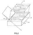
- FIG. 2 The operation of the diffraction-detection portion of the X-ray diffraction system manufactured in accordance with the present disclosure is depicted in FIG. 2 .
- the collimated beam of X-rays is emitted upon the sample 26.
- the incoming angle 40 of collimated beam of X-rays with respect to a surface of the sample 26 is adjusted until a portions of the X-rays diffract away from, rather than transmitting through, the sample 26.
- These diffracted X-rays will be captured by the detector 32. More specifically, the sample 26 will diffract X-rays in locations where micro-textured regions 38 are present. The capture of diffracted X-rays by the detector 32 confirms the presence of these micro-textured regions in the sample 26 under analysis.
- an x-ray diffraction system the system having a sample stage that includes three axes of translation and three axes of rotation, an x-ray source, a collimator that provides a collimated beam of x-rays with a divergence less than three degrees in all directions, a pixelated area detector whose distance between it and the sample stage is variable, and wherein the angle between the X-ray source and the pixelated area detector may be varied between zero degrees and one hundred and seventy degrees is provided.
- the pixelated detector is turned on and continuously creates an output signal.
- the X-ray source is turned on.
- the sample stage, the X-ray source and the detector are moved until a portion of the collimated beam of X-rays is diffracted from the metal sample into the detector.
- the output signal is sent to a computer.
- the method further comprises the step of translating the sample stage in one hundred micrometer increments along three axes of rotation. If the moving the sample stage is translation, then at a step 52, the method further includes the computer quantifying the shape, size, density and orientation of the micro-textured regions in the sample.
- the method further comprises the step of rotating the sample stage in one hundred micrometer increments along one axis of rotation. If the moving the sample stage is rotation, then at a step 56, the method further includes the computer quantifying the shape, size, density and orientation of the micro-textured regions in the sample.
- the X-ray diffraction system for the characterization of micro-textured regions in a metal sample containing more than one crystalline phase can find use in many industrial settings, such as in a manufacturing environment. More specifically, such a system finds use as a quality control tool in the manufacturing processes of aerospace component manufacturers, such as in the manufacture of gas turbine engines.
- a system includes a goniometer having a base, an automated tube arm rotatably associated with the base, an automated detector arm rotatably associated with the base, and an automated sample stage operatively associated with the base.
- the system may also include an x-ray source that radiatively supplies an array of non-collimated x-rays coupled to the automated tube arm.
- a collimator may also be included that is operatively associated with and downstream of the x-ray source, the collimator providing a beam of x-rays that has a divergence in all directions less than or about equal to three degrees.
- a pixelated area detector may be coupled to the automated detector arm. The detector may have a plurality of pixels that extend in a first direction from a point and extend in a second direction from the point, each pixel having a detection surface having a width between one micrometer and one thousand micrometers and the detector may generate an output signal.
- a computer may be in electrical communication with the goniometer and contain a first algorithm that controls the movement of the automated tube arm, the automated detector arm and the automated stage. The computer may also comprise a second algorithm that quantifies the shape, size, density and orientation of micro-textured regions in sample.
Landscapes
- Chemical & Material Sciences (AREA)
- Crystallography & Structural Chemistry (AREA)
- Physics & Mathematics (AREA)
- Health & Medical Sciences (AREA)
- Life Sciences & Earth Sciences (AREA)
- Analytical Chemistry (AREA)
- Biochemistry (AREA)
- General Health & Medical Sciences (AREA)
- General Physics & Mathematics (AREA)
- Immunology (AREA)
- Pathology (AREA)
- Analysing Materials By The Use Of Radiation (AREA)
Abstract
Description
- This disclosure generally relates to systems and methods for the analysis of samples and, more specifically, to x-ray topography systems and methods for the analysis of samples.
- Elemental titanium is an allotropic material. With proper conditioning, a sample of elemental titanium exists as a hexagonal close-packed (HCP) crystalline phase at ambient temperatures and pressures referred to as the alpha-phase. When the temperature of such sample is increased to around 890 degrees Celsius, a body-centered cubic (BCC) crystalline phase begins to form that remains stable to titanium's melting temperature of 1668 degrees Celsius. This BCC phase is known as the beta-phase. Alloying elements, such as aluminum or germanium, may be added to such sample to increase or depress its alpha-to-beta phase transition temperature. However, the alpha-phase and beta-phase crystalline phases always coexist to some degree if such sample is heated to or above a certain temperature coinciding with its alpha-to-beta phase transition temperature. When a sample contains both alpha and beta phases, it is referred to as dual-phase titanium.
- Literature reports that dual-phase titanium alloy samples are susceptible to the formation of a beta-phase interspersed with large, commonly oriented regions of alpha-phase particles known as micro-textured regions (MTR). While not conclusive, literature suggests that the formation of such MTRs may lead to a reduction in such samples' fatigue life during dwell loading. Literature additionally proposes that this reduction occurs when the samples are exposed to temperatures less than or equal to about 200 degrees Celsius when coupled with a stress level of 0.60 of the samples' yield strength.
- Different systems, such as X-ray crystallography machines, exist that can confirm the presence MTRs. However, such systems are not designed to characterize and quantify the shape, size, density and orientation of MTRs in samples. Instead, X-ray topography systems are better suited to undertake such analyses. Yet, X-ray topography systems are not without their limitations. Known X-ray topography systems may incorporate the necessary resolution to characterize and quantify the shape, size, density and orientation of MTRs in samples, but are best suited for use in a low-throughput, research-based environment. Other known X-ray topography systems include the speed necessary for a manufacturing environment, but lack the resolution necessary to characterize and quantify the shape, size, density and orientation of MTRs in samples. Thus a need exists for an X-ray topography system that combines the resolution found in research-based machinery with the greater speed necessary for manufacturing environments. The present disclosure is directed toward this end.
- In accordance with one aspect of the present disclosure, a system for the x-ray topography analysis of a sample is disclosed. The system may include a goniometer having a base, a tube arm rotatably associated with the base, a detector arm rotatably associated with the base and a sample stage operatively associated with the base. The system may further include an x-ray source that is operatively coupled with the tube arm and capable of emitting a non-collimated beam of x-rays and a collimator operatively associated with the x-ray source. The collimator may be capable of converting the non-collimated beam of x-rays into a collimated beam of x-rays having a quasi-rectangular shape with a divergence less than three degrees in all directions. A detector may be operatively coupled to the detector arm.
- In a refinement of the system for the x-ray topography analysis of a sample, the system, the sample stage may further include one to three axes of translation.
- In another refinement of the system for the x-ray topography analysis of a sample, the sample stage may translate in one hundred micrometer increments.
- In another refinement of the system for the x-ray topography analysis of a sample, the sample stage may further include one to three axes of rotation.
- In another refinement of the system for the x-ray topography analysis of a sample, the sample stage may rotate in one hundred micrometer increments.
- In another refinement of the system for the x-ray topography analysis of a sample, the detector may be an area detector including a plurality of pixels.
- In another refinement of the system for the x-ray topography analysis of a sample, each of the plurality of pixels may have a detection surface having a width between one micrometer and one thousand micrometers.
- In another refinement of the system for the x-ray topography analysis of a sample, the detector may have a detector surface and the detector arm may be an automated detector arm capable of varying the distance between the detector surface and the sample, or an angle between the collimated beam of x-rays and the detector surface.
- In another refinement of the system for the x-ray topography analysis of a sample, the tube arm and detector arm may be rotatable with respect to the base so that the angle between the collimated beam of x-rays and a diffracted beam of x-rays may vary between zero degrees and one hundred and seventy degrees.
- In another refinement of the system for the x-ray topography analysis of a sample, the detector may be in electrical communication with a computer capable of analyzing an output signal of the detector.
- In accordance with another aspect of the present disclosure, an X-ray diffraction system for the characterization of micro-textured regions in a metal sample containing more than one crystalline phase is disclosed. The system may include a goniometer having a base, an automated tube arm rotatably associated with the base, an automated detector arm rotatably associated with the base, and an automated sample stage operatively associated with the base. The system may also include an x-ray source that radiatively supplies an array of non-collimated x-rays coupled to the automated tube arm. A collimator may also be included that is operatively associated with and downstream of the x-ray source, the collimator providing a beam of x-rays that has a divergence in all directions less than or about equal to three degrees. A pixelated area detector may be coupled to the automated detector arm. The detector may have a plurality of pixels that extend in a first direction from a point and extend in a second direction from the point, each pixel having a detection surface having a width between one micrometer and one thousand micrometers and the detector may generate an output signal. Finally, a computer may be in electrical communication with the goniometer and contain a first algorithm that controls the movement of the automated tube arm, the automated detector arm and the automated stage.
- In a refinement of the X-ray diffraction system for the characterization of micro-textured regions in a metal sample containing more than one crystalline phase the output signal may be sent to the computer and the computer comprises a second algorithm that quantifies shape, size, density and orientation of the micro-textured regions in the sample based on the output signal.
- In another refinement of the X-ray diffraction system for the characterization of micro-textured regions in a metal sample containing more than one crystalline phase, the automated stage may also include three axes of translation, three axes of rotation and the first algorithm translates and rotates the stage in one hundred micrometer increments.
- In another refinement of the X-ray diffraction system for the characterization of micro-textured regions in a metal sample containing more than one crystalline phase, the first algorithm may vary the distance between the sample and the pixelated detector by moving the automated detector arm.
- In another refinement of the X-ray diffraction system for the characterization of micro-textured regions in a metal sample containing more than one crystalline phase the automated tube arm and automated detector arm may be rotatable with respect to the base, and the first algorithm may rotate these arms with respect to the base so that the angle between beam of x-rays and a diffracted beam of x-rays varies between zero degrees and one hundred and seventy degrees.
- In accordance with another aspect of the present disclosure, a method for the characterization of micro-textured regions in a metal sample containing more than one crystalline phase is disclosed. The method may include a first step of providing an x-ray diffraction system having a sample stage that includes three axes of translation and three axes of rotation, an x-ray source, a collimator that provides a collimated beam of x-rays with a divergence less than three degrees in all directions, a pixelated area detector whose distance between it and the sample stage is variable, and wherein the angle between the X-ray source and the pixelated area detector may be varied between zero degrees and one hundred and seventy degrees. In a next step, the pixelated area detector may be turned on and the detector may continuously create an output signal. In a next step, the X-ray source may be turned on. Then, the sample stage, X-ray source and the detector may be moved until a portion of the collimated beam of X-rays is diffracted from the metal sample into the detector. Finally, the output signal may be sent to a computer.
- In a refinement of the method for the characterization of micro-textured regions in a metal sample containing more than one crystalline phase, the method of
claim 16, the moving of the sample stage is translation and the method may further include the step of translating the sample stage in one hundred micrometer increments along all three axes of translation. - In another refinement of the method for the characterization of micro-textured regions in a metal sample containing more than one crystalline phase, the computer quantifies the shape, size, density and orientation of the micro-textured regions in the sample.
- In another refinement of the method for the characterization of micro-textured regions in a metal sample containing more than one crystalline phase, the moving of the sample stage is rotation and the method may include the step of rotating the sample stage in one hundred micrometer increments along one axis of rotation.
- In another refinement of the method for the characterization of micro-textured regions in a metal sample containing more than one crystalline phase, the computer quantifies the shape, size, density and orientation of the micro-textured regions in the sample.
- According to a first aspect, the present disclosure provides a system for the x-ray topography analysis of a sample, comprising: a goniometer, the goniometer having a base, a tube arm rotatably associated with the base, a detector arm rotatably associated with the base, and a sample stage operatively associated with the base; an x-ray source, the x-ray source operatively coupled with the tube arm and capable of emitting a non-collimated beam of x-rays; a collimator operatively associated with the x-ray source, the collimator capable of converting the non-collimated beam of x-rays into a collimated beam of x-rays having a quasi-rectangular shape with a divergence less than three degrees in all directions; and a detector operatively coupled to the detector arm.
- In addition to one or more of the features described above, or as an alternative to any of the foregoing embodiments, the stage further includes one to three axes of translation.
- In addition to one or more of the features described above, or as an alternative to any of the foregoing embodiments, the stage translates in one hundred micrometer increments.
- In addition to one or more of the features described above, or as an alternative to any of the foregoing embodiments, the stage further includes one to three axes of rotation.
- In addition to one or more of the features described above, or as an alternative to any of the foregoing embodiments, the stage rotates in one hundred micrometer increments.
- In addition to one or more of the features described above, or as an alternative to any of the foregoing embodiments, the detector is an area detector including a plurality of pixels.
- In addition to one or more of the features described above, or as an alternative to any of the foregoing embodiments, each of the plurality of pixels has a detection surface having a width between one micrometer and one thousand micrometers.
- In addition to one or more of the features described above, or as an alternative to any of the foregoing embodiments, the detector has a detector surface and the detector arm is an automated detector arm capable of varying the distance between the detector surface and the sample or an angle between the collimated beam of x-rays and the detector surface.
- In addition to one or more of the features described above, or as an alternative to any of the foregoing embodiments, the tube arm and detector arm are rotatable with respect to the base so that the angle between the collimated beam of x-rays and a diffracted beam of x-rays may vary between zero degrees and one hundred and seventy degrees.
- In addition to one or more of the features described above, or as an alternative to any of the foregoing embodiments, the detector is in electrical communication with a computer capable of analyzing an output signal of the detector.
- According to a second aspect, the present disclosure provides an X-ray diffraction system for the characterization of micro-textured regions in a metal sample containing more than one crystalline phase, comprising: a goniometer, the goniometer having a base, an automated tube arm rotatably associated with the base, an automated detector arm rotatably associated with the base, and an automated sample stage operatively associated with the base; an x-ray source, the x-ray source coupled to the automated tube arm, the x-ray source radiatively supplying an array of non-collimated x-rays; a collimator, operatively associated with and downstream of the x-ray source, the collimator providing a beam of x-rays that has a divergence in all directions less than or about equal to three degrees; a pixelated detector coupled to the automated detector arm, the detector having a plurality of pixels that extend in a first direction from a point and extend in a second direction from the point, each pixel having a detection surface having a width between one micrometer and one thousand micrometers, the detector generating an output signal; a computer in electrical communication with the goniometer having a first algorithm that controls the movement of the automated tube arm, the automated detector arm and the automated stage.
- In addition to one or more of the features described above, or as an alternative to any of the foregoing embodiments, the output signal is sent to the computer and the computer comprises a second algorithm that quantifies shape, size, density and orientation of the micro-textured regions in the sample based on the output signal.
- In addition to one or more of the features described above, or as an alternative to any of the foregoing embodiments, the automated stage further includes three axes of translation, three axes of rotation and the first algorithm translates and rotates the stage in one hundred micrometer increments.
- In addition to one or more of the features described above, or as an alternative to any of the foregoing embodiments, the first algorithm varies distance between the sample and the pixelated detector by moving the automated detector arm.
- In addition to one or more of the features described above, or as an alternative to any of the foregoing embodiments, the automated tube arm and automated detector arm are rotatable with respect to the base, and the first algorithm rotates these arms with respect to the base so that the angle between beam of x-rays and a diffracted beam of x-rays varies between zero degrees and one hundred and seventy degrees.
- According to a third aspect, the present invention provides a method for the characterization of micro-textured regions in a metal sample containing more than one crystalline phase, comprising: providing an x-ray diffraction system, the system having a sample stage that includes three axes of translation and three axes of rotation, an x-ray source, a collimator that provides a collimated beam of x-rays with a divergence less than three degrees in all directions, a pixelated area detector whose distance between it and the sample stage is variable, and wherein the angle between the X-ray source and the pixelated area detector may be varied between zero degrees and one hundred and seventy degrees; activating the pixelated area detector, the detector continuously creating an output signal; turning on the X-ray source; moving the sample stage, the X-ray source and the detector until a portion of the collimated beam of X-rays is diffracted from the metal sample into the detector; and sending the output signal to a computer.
- In addition to one or more of the features described above, or as an alternative to any of the foregoing embodiments, the moving the sample stage is translation and further comprises the step of translating the sample stage in one hundred micrometer increments along all three axes of translation.
- In addition to one or more of the features described above, or as an alternative to any of the foregoing embodiments, the computer quantifies the shape, size, density and orientation of the micro-textured regions in the sample.
- In addition to one or more of the features described above, or as an alternative to any of the foregoing embodiments, the moving the sample stage is rotation and further comprises the step of rotating the sample stage in one hundred micrometer increments along one axis of rotation.
- In addition to one or more of the features described above, or as an alternative to any of the foregoing embodiments, the computer quantifies the shape, size, density and orientation of the micro-textured regions in the sample.
- Certain exemplary embodiments of the present disclosure will now be described in greater detail by way of example only and with reference to the accompanying drawings, in which:
-
FIG. 1 is a side elevation view of an X-ray diffraction system for the characterization of micro-textured regions in a metal sample containing more than one crystalline phase constructed in accordance with an exemplary embodiment of the present disclosure. -
FIG. 2 is a partial isometric side view depicting the operation of the diffraction-detection portion of X-ray diffraction system ofFIG. 1 . -
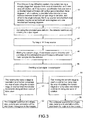
FIG. 3 is a flowchart depicting an exemplary method for the characterization of micro-textured regions in a metal sample containing more than one crystalline phase utilizing a system depicted inFIG. 1 . - Referring now to the drawings, and with specific reference to
FIG. 1 , an X-ray diffraction system for the characterization of micro-textured regions in a metal sample containing more than one crystalline phase constructed in accordance with an exemplary embodiment of the present disclosure is generally referred to byreference numeral 10. The X-ray diffraction system includes agoniometer 12 having a base 14, atube arm 16 rotatably associated with thebase 14, adetector arm 18 rotatably associated with thebase 14 and asample stage 20 operatively associated with thebase 14. - The
X-ray diffraction system 10 may further include acomputer 22. Thiscomputer 22 may be in electrical communication with thegoniometer 12 and include afirst algorithm 24. Thefirst algorithm 24 may control the movement of thetube arm 16, thedetector arm 18 and thesample stage 20. Accordingly, the movement of thetube arm 16, thedetector arm 18 andsample stage 20 may be automated by their interaction with thecomputer 22. - The
tube arm 16 may rotate around thebase 14 between an angle of zero degrees and one hundred seventy degrees. Like thetube arm 16, thedetector arm 18 may also rotate around thebase 14 between an angle of zero degrees and one hundred and seventy degrees. Thearms base 14 so that asample 26 may be analyzed from multiple locations. - Still referring to
FIG. 1 , the X-ray diffraction system further comprises anX-ray source 28 that is operatively coupled to thetube arm 16. Since theX-ray source 28 is coupled to thetube arm 16, the movement of thesource 28 coincides with the automated movement of thearm 16. ThisX-ray source 28 is capable of radiatively supplying an array of non-collimated x-rays. While not all inclusive, examples of anx-ray source 28 that may be used with this system include a copper target, molybdenum target, nickel target, titanium target and silver target sources. - A
collimator 30 may be operatively associated with and located downstream of theX-ray source 28. As the X-rays from thesource 28 pass through thecollimator 30, the array of non-collimated X-rays may be converted into a collimated beam of x-rays. In one embodiment, this collimated beam may have a quasi-rectangular shape with a divergence less than three degrees in all directions. In another embodiment, this collimated beam may have a quasi-rectangular shape with a divergence less than two degrees in all directions. In a further embodiment, this collimated beam may have a quasi-rectangular shape with a divergence less than one degree in all directions. While not meant to be exhaustive,collimator 30 that may be used with asystem 10 constructed in accordance with the present disclosure include slits and X-ray lenses on optical fibers. - This X-ray diffraction system may further include a
detector 32 that is operatively coupled to thedetector arm 18. Since thedetector 32 is coupled to thedetector arm 18, the movement of thedetector 32 coincides with the automated movement of thedetector arm 18. Additionally, thetube arm 18 may also move so that the distance between thesample 26 and thedetector 32 is adjustable. This movement allows for focusing of thedetector 32 with respect to thesample 26 when thesystem 10 is in operation. - The
detector 32 may be a pixelated area detector that comprises a plurality of pixels that extend in a first direction from a point, and the plurality of pixels may also extend in a second direction from the same point thereby generating an area of pixels. Each pixel of thisdetector 32 may act as an individual detector having a detection surface, and the width of each detection surface may be between one micrometer and one thousand micrometers. In one instance, thedetector 32 may be a charge-coupled device. In another instance, adetector 32 that may be used with thissystem 10 is an active pixel sensor. In yet other examples, thedetector 32 may be a scintillation detector, Xe-field detector or even a solid-state detector. - The
detector 32 may generate an output signal 34. This output signal 34 may then be sent to thecomputer 22 that comprises asecond algorithm 36 that is utilized to characterize thesample 26 for the presence ofmicro-textured regions 38. Thesecond algorithm 36 may further quantify the shape, size, density and orientation of anymicro-textured regions 38 present in thesample 26. Limits may be set on the shape, size, density and orientation of anymicro-textured regions 38 in thesample 26, and thecomputer 22 may provide a report whether thesample 26 falls below such limits. - If the
system 10 is utilized in a manufacturing environment, then thecomputer 22 may be preloaded with multiplefirst algorithms 24 based on the shape of thesample 26 such as by Computer Aided Design (CAD) drawings. Then, when asample 26 having a particular shape is loaded onto thesystem 10, afirst algorithm 24 specific to the shape of thesample 26 may be utilized to control the movement of thetube arm 16,detector arm 18 and thesample stage 20. - The operation of the diffraction-detection portion of the X-ray diffraction system manufactured in accordance with the present disclosure is depicted in
FIG. 2 . As seen there, the collimated beam of X-rays is emitted upon thesample 26. Then, theincoming angle 40 of collimated beam of X-rays with respect to a surface of thesample 26 is adjusted until a portions of the X-rays diffract away from, rather than transmitting through, thesample 26. These diffracted X-rays will be captured by thedetector 32. More specifically, thesample 26 will diffract X-rays in locations wheremicro-textured regions 38 are present. The capture of diffracted X-rays by thedetector 32 confirms the presence of these micro-textured regions in thesample 26 under analysis. - Referring next to
FIG. 3 , steps of a method for the characterization of micro-textured regions in a metal sample containing more than one crystalline phase are illustrated. At astep 40, an x-ray diffraction system, the system having a sample stage that includes three axes of translation and three axes of rotation, an x-ray source, a collimator that provides a collimated beam of x-rays with a divergence less than three degrees in all directions, a pixelated area detector whose distance between it and the sample stage is variable, and wherein the angle between the X-ray source and the pixelated area detector may be varied between zero degrees and one hundred and seventy degrees is provided. At astep 42, the pixelated detector is turned on and continuously creates an output signal. At astep 44, the X-ray source is turned on. At astep 46, the sample stage, the X-ray source and the detector are moved until a portion of the collimated beam of X-rays is diffracted from the metal sample into the detector. At astep 48, the output signal is sent to a computer. - If the moving the sample stage is translation, then at a
step 50, the method further comprises the step of translating the sample stage in one hundred micrometer increments along three axes of rotation. If the moving the sample stage is translation, then at astep 52, the method further includes the computer quantifying the shape, size, density and orientation of the micro-textured regions in the sample. - If the moving the sample stage is rotation, then at a
step 54, the method further comprises the step of rotating the sample stage in one hundred micrometer increments along one axis of rotation. If the moving the sample stage is rotation, then at astep 56, the method further includes the computer quantifying the shape, size, density and orientation of the micro-textured regions in the sample. - In operation, the X-ray diffraction system for the characterization of micro-textured regions in a metal sample containing more than one crystalline phase can find use in many industrial settings, such as in a manufacturing environment. More specifically, such a system finds use as a quality control tool in the manufacturing processes of aerospace component manufacturers, such as in the manufacture of gas turbine engines. Such a system includes a goniometer having a base, an automated tube arm rotatably associated with the base, an automated detector arm rotatably associated with the base, and an automated sample stage operatively associated with the base. The system may also include an x-ray source that radiatively supplies an array of non-collimated x-rays coupled to the automated tube arm. A collimator may also be included that is operatively associated with and downstream of the x-ray source, the collimator providing a beam of x-rays that has a divergence in all directions less than or about equal to three degrees. A pixelated area detector may be coupled to the automated detector arm. The detector may have a plurality of pixels that extend in a first direction from a point and extend in a second direction from the point, each pixel having a detection surface having a width between one micrometer and one thousand micrometers and the detector may generate an output signal. Finally, a computer may be in electrical communication with the goniometer and contain a first algorithm that controls the movement of the automated tube arm, the automated detector arm and the automated stage. The computer may also comprise a second algorithm that quantifies the shape, size, density and orientation of micro-textured regions in sample.
- The above description is meant to be representative only, and thus modifications may be made to the embodiments described herein without departing from the scope of the disclosure. Thus, these modifications fall within the scope of present disclosure and are intended to fall within the appended claims.
- The following clauses set out features of the present disclosure which may or may not presently be claimed but which may form basis for future amendments and/or a divisional application.
- 1. A system for the x-ray topography analysis of a sample, comprising:
- a goniometer, the goniometer having a base, a tube arm rotatably associated with the base, a detector arm rotatably associated with the base, and a sample stage operatively associated with the base;
- an x-ray source, the x-ray source operatively coupled with the tube arm and capable of emitting a non-collimated beam of x-rays;
- a collimator operatively associated with the x-ray source, the collimator capable of converting the non-collimated beam of x-rays into a collimated beam of x-rays having a quasi-rectangular shape with a divergence less than three degrees in all directions; and
- a detector operatively coupled to the detector arm.
- 2. The system of clause 1, wherein the stage further includes one to three axes of translation.
- 3. The system of clause 2, wherein the stage translates in one hundred micrometer increments.
- 4. The system of clause 1, wherein the stage further includes one to three axes of rotation.
- 5. The system of clause 4, wherein the stage rotates in one hundred micrometer increments.
- 6. The system of clause 1, wherein the detector is an area detector including a plurality of pixels.
- 7. The system of clause 6, wherein each of the plurality of pixels has a detection surface having a width between one micrometer and one thousand micrometers.
- 8. The system of clause 1, wherein the detector has a detector surface and the detector arm is an automated detector arm capable of varying the distance between the detector surface and the sample or an angle between the collimated beam of x-rays and the detector surface.
- 9. The system of clause 1, wherein the tube arm and detector arm are rotatable with respect to the base so that the angle between the collimated beam of x-rays and a diffracted beam of x-rays may vary between zero degrees and one hundred and seventy degrees.
- 10. The system of clause 1, wherein the detector is in electrical communication with a computer capable of analyzing an output signal of the detector.
- 11. An X-ray diffraction system for the characterization of micro-textured regions in a metal sample containing more than one crystalline phase, comprising:
- a goniometer, the goniometer having a base, an automated tube arm rotatably associated with the base, an automated detector arm rotatably associated with the base, and an automated sample stage operatively associated with the base;
- an x-ray source, the x-ray source coupled to the automated tube arm, the x-ray source radiatively supplying an array of non-collimated x-rays;
- a collimator, operatively associated with and downstream of the x-ray source, the collimator providing a beam of x-rays that has a divergence in all directions less than or about equal to three degrees;
- a pixelated detector coupled to the automated detector arm, the detector having a plurality of pixels that extend in a first direction from a point and extend in a second direction from the point, each pixel having a detection surface having a width between one micrometer and one thousand micrometers, the detector generating an output signal;
- a computer in electrical communication with the goniometer having a first algorithm that controls the movement of the automated tube arm, the automated detector arm and the automated stage.
- 12. The system of clause 11, wherein the output signal is sent to the computer and the computer comprises a second algorithm that quantifies shape, size, density and orientation of the micro-textured regions in the sample based on the output signal.
- 13. The system of clause 11, wherein the automated stage further includes three axes of translation, three axes of rotation and the first algorithm translates and rotates the stage in one hundred micrometer increments.
- 14. The system of clause 11, wherein the first algorithm varies distance between the sample and the pixelated detector by moving the automated detector arm.
- 15. The system of clause 11, wherein the automated tube arm and automated detector arm are rotatable with respect to the base, and the first algorithm rotates these arms with respect to the base so that the angle between beam of x-rays and a diffracted beam of x-rays varies between zero degrees and one hundred and seventy degrees.
- 16. A method for the characterization of micro-textured regions in a metal sample containing more than one crystalline phase, comprising:
- providing an x-ray diffraction system, the system having a sample stage that includes three axes of translation and three axes of rotation, an x-ray source, a collimator that provides a collimated beam of x-rays with a divergence less than three degrees in all directions, a pixelated area detector whose distance between it and the sample stage is variable, and wherein the angle between the X-ray source and the pixelated area detector may be varied between zero degrees and one hundred and seventy degrees;
- activating the pixelated area detector, the detector continuously creating an output signal;
- turning on the X-ray source;
- moving the sample stage, the X-ray source and the detector until a portion of the collimated beam of X-rays is diffracted from the metal sample into the detector; and
- sending the output signal to a computer.
- 17. The method of
clause 16, wherein the moving the sample stage is translation and further comprises the step of translating the sample stage in one hundred micrometer increments along all three axes of translation. - 18. The method of clause 17, wherein the computer quantifies the shape, size, density and orientation of the micro-textured regions in the sample.
- 19. The method of
clause 16, wherein the moving the sample stage is rotation and further comprises the step of rotating the sample stage in one hundred micrometer increments along one axis of rotation. - 20. The method of clause 19, wherein the computer quantifies the shape, size, density and orientation of the micro-textured regions in the sample.
Claims (15)
- A system (10) for the x-ray topography analysis of a sample, comprising:a goniometer (12), the goniometer having a base (14), a tube arm (16) rotatably associated with the base, a detector arm (18) rotatably associated with the base, and a sample stage (20) operatively associated with the base;an x-ray source (28), the x-ray source operatively coupled with the tube arm and capable of emitting a non-collimated beam of x-rays;a collimator (30) operatively associated with the x-ray source, the collimator capable of converting the non-collimated beam of x-rays into a collimated beam of x-rays having a quasi-rectangular shape with a divergence less than three degrees in all directions; anda detector (32) operatively coupled to the detector arm.
- The system of claim 1, wherein the stage further includes one to three axes of translation, preferably wherein the stage translates in one hundred micrometer increments; and/or
wherein the stage further includes one to three axes of rotation, preferably wherein the stage rotates in one hundred micrometer increments. - The system of claim 1 or 2, wherein the detector is an area detector including a plurality of pixels, preferably wherein each of the plurality of pixels has a detection surface having a width between one micrometer and one thousand micrometers.
- The system of claim 1, 2, or 3, wherein the detector has a detector surface and the detector arm is an automated detector arm capable of varying the distance between the detector surface and the sample or an angle between the collimated beam of x-rays and the detector surface.
- The system of any preceding claim, wherein the tube arm and detector arm are rotatable with respect to the base so that the angle between the collimated beam of x-rays and a diffracted beam of x-rays may vary between zero degrees and one hundred and seventy degrees.
- The system of any preceding claim, wherein the detector is in electrical communication with a computer (22) capable of analyzing an output signal of the detector.
- An X-ray diffraction system (10) for the characterization of micro-textured regions in a metal sample containing more than one crystalline phase, comprising:a goniometer (12), the goniometer having a base (14), an automated tube arm (16) rotatably associated with the base, an automated detector arm (18) rotatably associated with the base, and an automated sample stage (20) operatively associated with the base;an x-ray source (28), the x-ray source coupled to the automated tube arm, the x-ray source radiatively supplying an array of non-collimated x-rays;a collimator (30), operatively associated with and downstream of the x-ray source, the collimator providing a beam of x-rays that has a divergence in all directions less than or about equal to three degrees;a pixelated detector (32) coupled to the automated detector arm, the detector having a plurality of pixels that extend in a first direction from a point and extend in a second direction from the point, each pixel having a detection surface having a width between one micrometer and one thousand micrometers, the detector generating an output signal;a computer (22) in electrical communication with the goniometer having a first algorithm that controls the movement of the automated tube arm, the automated detector arm and the automated stage.
- The system of claim 7, wherein the output signal is sent to the computer and the computer comprises a second algorithm that quantifies shape, size, density and orientation of the micro-textured regions in the sample based on the output signal.
- The system of claim 7 or 8, wherein the automated stage further includes three axes of translation, three axes of rotation and the first algorithm translates and rotates the stage in one hundred micrometer increments.
- The system of any of claims 7 to 9, wherein the first algorithm varies distance between the sample and the pixelated detector by moving the automated detector arm.
- The system of any of claims 7 to 10, wherein the automated tube arm and automated detector arm are rotatable with respect to the base, and the first algorithm rotates these arms with respect to the base so that the angle between beam of x-rays and a diffracted beam of x-rays varies between zero degrees and one hundred and seventy degrees.
- A method for the characterization of micro-textured regions in a metal sample containing more than one crystalline phase, comprising:providing (40) an x-ray diffraction system (10), the system having a sample stage (20) that includes three axes of translation and three axes of rotation, an x-ray source (28), a collimator (30) that provides a collimated beam of x-rays with a divergence less than three degrees in all directions, a pixelated area detector (32) whose distance between it and the sample stage is variable, and wherein the angle between the X-ray source and the pixelated area detector may be varied between zero degrees and one hundred and seventy degrees;activating (42) the pixelated area detector, the detector continuously creating an output signal;turning on (44) the X-ray source;moving (46) the sample stage, the X-ray source and the detector until a portion of the collimated beam of X-rays is diffracted from the metal sample into the detector; andsending (48) the output signal to a computer.
- The method of claim 12, wherein the moving the sample stage is translation (50) and further comprises the step of translating the sample stage in one hundred micrometer increments along all three axes of translation.
- The method of claims 12 or 13, wherein the moving the sample stage is rotation (54) and further comprises the step of rotating the sample stage in one hundred micrometer increments along one axis of rotation.
- The method of claim 12, 13 or 14, wherein the computer quantifies (52, 56) the shape, size, density and orientation of the micro-textured regions in the sample.
Applications Claiming Priority (1)
| Application Number | Priority Date | Filing Date | Title |
|---|---|---|---|
| US14/600,511 US10161887B2 (en) | 2015-01-20 | 2015-01-20 | Systems and methods for materials analysis |
Publications (1)
| Publication Number | Publication Date |
|---|---|
| EP3048442A1 true EP3048442A1 (en) | 2016-07-27 |
Family
ID=55182272
Family Applications (1)
| Application Number | Title | Priority Date | Filing Date |
|---|---|---|---|
| EP16152126.5A Pending EP3048442A1 (en) | 2015-01-20 | 2016-01-20 | X-ray topography systems and methods for analysing micro-textured regions in metal samples |
Country Status (2)
| Country | Link |
|---|---|
| US (2) | US10161887B2 (en) |
| EP (1) | EP3048442A1 (en) |
Families Citing this family (4)
| Publication number | Priority date | Publication date | Assignee | Title |
|---|---|---|---|---|
| US10161887B2 (en) | 2015-01-20 | 2018-12-25 | United Technologies Corporation | Systems and methods for materials analysis |
| US11519798B2 (en) * | 2018-12-18 | 2022-12-06 | Metal Industries Research & Development Centre | Residual stress detection device and detection method thereof |
| CN111380880B (en) * | 2018-12-28 | 2023-04-07 | 中国兵器工业第五九研究所 | Diffraction device and method for nondestructive testing of crystal orientation uniformity inside workpiece |
| US11333633B2 (en) * | 2019-09-09 | 2022-05-17 | Raytheon Technologies Corporation | Microtexture region characterization systems and methods |
Citations (6)
| Publication number | Priority date | Publication date | Assignee | Title |
|---|---|---|---|---|
| DE1961648A1 (en) * | 1968-12-10 | 1970-06-18 | Enraf Nonius | Goniometric device, especially for a refractometer or a similar device |
| DE4236291A1 (en) * | 1992-10-23 | 1994-04-28 | Freiberger Praezisionsmechanik | Texture and stress analysis and crystal orientation determn. method - involves exposing specimen to x-rays and measuring radiation from specimen with energy resolution detector at various output angles |
| EP1193492A1 (en) * | 2000-09-27 | 2002-04-03 | Euratom | A micro beam collimator for high resolution XRD investigations with conventional diffractometers |
| EP1947448A1 (en) * | 2007-01-19 | 2008-07-23 | Panalytical B.V. | X-ray Diffraction Equipment for X-ray Scattering |
| US7848489B1 (en) * | 2009-04-02 | 2010-12-07 | Broker Axs, Inc. | X-ray diffractometer having co-exiting stages optimized for single crystal and bulk diffraction |
| US8548123B2 (en) * | 2010-04-29 | 2013-10-01 | Bruker Axs, Inc. | Method and apparatus for using an area X-ray detector as a point detector in an X-ray diffractometer |
Family Cites Families (25)
| Publication number | Priority date | Publication date | Assignee | Title |
|---|---|---|---|---|
| US5148458A (en) | 1990-01-18 | 1992-09-15 | Clayton Ruud | Method and apparatus for simultaneous phase composition and residual stress measurement by x-ray diffraction |
| US6118850A (en) | 1997-02-28 | 2000-09-12 | Rutgers, The State University | Analysis methods for energy dispersive X-ray diffraction patterns |
| EP1149282A2 (en) * | 1998-12-18 | 2001-10-31 | Symyx Technologies, Inc. | Apparatus and method for characterizing libraries of different materials using x-ray scattering |
| JP3944330B2 (en) * | 1999-04-12 | 2007-07-11 | 株式会社リガク | X-ray diffractometer and method for measuring X-ray rocking curve |
| GB0222334D0 (en) * | 2001-10-04 | 2002-10-30 | X Ray Res Gmbh | Automatic adjusting method for a goniometer and associated device |
| JP3904543B2 (en) * | 2003-10-14 | 2007-04-11 | 株式会社リガク | X-ray crystal orientation measuring apparatus and X-ray crystal orientation measuring method |
| CN102890095B (en) * | 2004-07-08 | 2015-11-18 | 护照系统公司 | For the method and system of the average atomic number and quality of determining material |
| US7242745B2 (en) * | 2004-07-29 | 2007-07-10 | Bob Baoping He | X-ray diffraction screening system convertible between reflection and transmission modes |
| US7269245B2 (en) * | 2004-07-30 | 2007-09-11 | Bruker Axs, Inc. | Combinatorial screening system and X-ray diffraction and Raman spectroscopy |
| US7190762B2 (en) * | 2004-10-29 | 2007-03-13 | Broker Axs, Inc | Scanning line detector for two-dimensional x-ray diffractometer |
| JP4074874B2 (en) * | 2005-06-30 | 2008-04-16 | 株式会社リガク | X-ray diffractometer |
| JP4711430B2 (en) * | 2006-08-01 | 2011-06-29 | 株式会社リガク | X-ray diffractometer |
| WO2008097345A2 (en) * | 2006-08-10 | 2008-08-14 | X-Ray Optical Systems, Inc. | Wide parallel beam diffraction imaging method and system |
| US8322221B1 (en) | 2009-03-26 | 2012-12-04 | The United States Of America As Represented By The Secretary Of The Air Force | Non-contact high resolution near field acoustic imaging system |
| JP5788153B2 (en) * | 2010-07-28 | 2015-09-30 | 株式会社リガク | X-ray diffraction method and portable X-ray diffractometer using the same |
| JP5599062B2 (en) * | 2010-12-06 | 2014-10-01 | 株式会社リガク | X-ray diffraction apparatus and X-ray diffraction measurement method |
| JP5511020B2 (en) * | 2011-11-24 | 2014-06-04 | 株式会社リガク | X-ray analyzer |
| JP5838114B2 (en) * | 2012-04-02 | 2015-12-24 | 株式会社リガク | X-ray topography equipment |
| US9557299B2 (en) * | 2013-03-13 | 2017-01-31 | Mrl Materials Resources Llc | Adaptive data collection for local states of a material |
| US9188551B2 (en) * | 2013-09-20 | 2015-11-17 | Morpho Detction, Llc | Angle-dependent X-ray diffraction imaging system and method of operating the same |
| JP6270214B2 (en) * | 2013-11-25 | 2018-01-31 | 株式会社リガク | Optical axis adjustment method for X-ray analyzer and X-ray analyzer |
| US9976971B2 (en) * | 2014-03-06 | 2018-05-22 | United Technologies Corporation | Systems and methods for X-ray diffraction |
| JP6202684B2 (en) * | 2014-06-05 | 2017-09-27 | 株式会社リガク | X-ray diffractometer |
| US10161887B2 (en) | 2015-01-20 | 2018-12-25 | United Technologies Corporation | Systems and methods for materials analysis |
| US10060865B2 (en) * | 2015-03-10 | 2018-08-28 | Lyncean Technologies, Inc. | Measurement of critical dimensions of nanostructures using X-ray grazing incidence in-plane diffraction |
-
2015
- 2015-01-20 US US14/600,511 patent/US10161887B2/en active Active
-
2016
- 2016-01-20 EP EP16152126.5A patent/EP3048442A1/en active Pending
-
2018
- 2018-11-08 US US16/184,068 patent/US10458929B2/en active Active
Patent Citations (6)
| Publication number | Priority date | Publication date | Assignee | Title |
|---|---|---|---|---|
| DE1961648A1 (en) * | 1968-12-10 | 1970-06-18 | Enraf Nonius | Goniometric device, especially for a refractometer or a similar device |
| DE4236291A1 (en) * | 1992-10-23 | 1994-04-28 | Freiberger Praezisionsmechanik | Texture and stress analysis and crystal orientation determn. method - involves exposing specimen to x-rays and measuring radiation from specimen with energy resolution detector at various output angles |
| EP1193492A1 (en) * | 2000-09-27 | 2002-04-03 | Euratom | A micro beam collimator for high resolution XRD investigations with conventional diffractometers |
| EP1947448A1 (en) * | 2007-01-19 | 2008-07-23 | Panalytical B.V. | X-ray Diffraction Equipment for X-ray Scattering |
| US7848489B1 (en) * | 2009-04-02 | 2010-12-07 | Broker Axs, Inc. | X-ray diffractometer having co-exiting stages optimized for single crystal and bulk diffraction |
| US8548123B2 (en) * | 2010-04-29 | 2013-10-01 | Bruker Axs, Inc. | Method and apparatus for using an area X-ray detector as a point detector in an X-ray diffractometer |
Non-Patent Citations (1)
| Title |
|---|
| ADAM L. PILCHAK ET AL: "A Quantitative Assessment of Microtexture in Titanium Alloys using Destructive and Nondestructive Methods", MICROSCOPY AND MICROANALYSIS, vol. 20, no. S3, 27 August 2014 (2014-08-27), pages 1448 - 1449, XP055273295, ISSN: 1431-9276, DOI: 10.1017/S1431927614008976 * |
Also Published As
| Publication number | Publication date |
|---|---|
| US20190086343A1 (en) | 2019-03-21 |
| US20160209340A1 (en) | 2016-07-21 |
| US10161887B2 (en) | 2018-12-25 |
| US10458929B2 (en) | 2019-10-29 |
Similar Documents
| Publication | Publication Date | Title |
|---|---|---|
| US10458929B2 (en) | Systems and methods for materials analysis | |
| Tamura | XMAS: A versatile tool for analyzing synchrotron X-ray microdiffraction data | |
| Jackson et al. | Dictionary indexing of electron back-scatter diffraction patterns: a hands-on tutorial | |
| EP2239560A1 (en) | X-ray examining apparatus and x-ray examining method | |
| Geandier et al. | Development of a synchrotron biaxial tensile device for in situ characterization of thin films mechanical response | |
| US11933747B2 (en) | System and method for in-situ X-ray diffraction-based real-time monitoring of microstructure properties of printing objects | |
| JP6606503B2 (en) | Method for mapping crystal orientation in a sample made of polycrystalline material | |
| JP6839645B2 (en) | Computer tomography | |
| JP2011095224A (en) | Dispersive crystal, wavelength dispersion type x-ray analysis device, and element distribution measuring method | |
| Stewart et al. | Characterizing single isolated radiation-damage events from molecular dynamics via virtual diffraction methods | |
| Ben-Gharbia et al. | Kinematic design of manipulators with seven revolute joints optimized for fault tolerance | |
| Pateras et al. | Combining Laue diffraction with Bragg coherent diffraction imaging at 34-ID-C | |
| US20180082444A1 (en) | Tomographic imaging method | |
| US10908104B2 (en) | Radiation analysis apparatus | |
| Álvarez-Murga et al. | Development of synchrotron X-ray micro-tomography under extreme conditions of pressure and temperature | |
| Bouscaud et al. | Strain resolution of scanning electron microscopy based Kossel microdiffraction | |
| Schmidt et al. | Structural refinements of the individual grains within polycrystals and powders | |
| Butler et al. | Origin of preferred orientation in an isotropic material: High pressure synthesis of bc8-Si | |
| EP2775296A1 (en) | An X-ray diffraction method of mapping grain structures in a crystalline material sample, and an X-ray diffraction apparatus | |
| Lhuissier et al. | High-temperature deformation followed in situ by X-ray microtomography: a methodology to track features under large strain | |
| Arnaud et al. | A laboratory transmission diffraction Laue setup to evaluate single-crystal quality | |
| Lu et al. | A simplified focusing and astigmatism correction method for a scanning electron microscope | |
| Thomas et al. | X-ray diffraction imaging of deformations in thin films and nano-objects | |
| Zhang et al. | Mapping nanocrystal orientations via scanning Laue diffraction microscopy for multi-peak Bragg coherent diffraction imaging | |
| Porta et al. | Processing incommensurately modulated protein diffraction data with Eval15 |
Legal Events
| Date | Code | Title | Description |
|---|---|---|---|
| PUAI | Public reference made under article 153(3) epc to a published international application that has entered the european phase |
Free format text: ORIGINAL CODE: 0009012 |
|
| AK | Designated contracting states |
Kind code of ref document: A1 Designated state(s): AL AT BE BG CH CY CZ DE DK EE ES FI FR GB GR HR HU IE IS IT LI LT LU LV MC MK MT NL NO PL PT RO RS SE SI SK SM TR |
|
| AX | Request for extension of the european patent |
Extension state: BA ME |
|
| RAP1 | Party data changed (applicant data changed or rights of an application transferred) |
Owner name: UNITED TECHNOLOGIES CORPORATION |
|
| STAA | Information on the status of an ep patent application or granted ep patent |
Free format text: STATUS: REQUEST FOR EXAMINATION WAS MADE |
|
| 17P | Request for examination filed |
Effective date: 20170127 |
|
| RBV | Designated contracting states (corrected) |
Designated state(s): AL AT BE BG CH CY CZ DE DK EE ES FI FR GB GR HR HU IE IS IT LI LT LU LV MC MK MT NL NO PL PT RO RS SE SI SK SM TR |
|
| STAA | Information on the status of an ep patent application or granted ep patent |
Free format text: STATUS: EXAMINATION IS IN PROGRESS |
|
| 17Q | First examination report despatched |
Effective date: 20180709 |
|
| REG | Reference to a national code |
Ref country code: DE Ref legal event code: R079 Free format text: PREVIOUS MAIN CLASS: G01N0023200000 Ipc: G01N0023207000 |
|
| RIC1 | Information provided on ipc code assigned before grant |
Ipc: G01N 23/20016 20180101ALI20200619BHEP Ipc: G01N 23/207 20180101AFI20200619BHEP |
|
| RAP1 | Party data changed (applicant data changed or rights of an application transferred) |
Owner name: RAYTHEON TECHNOLOGIES CORPORATION |
|
| RAP3 | Party data changed (applicant data changed or rights of an application transferred) |
Owner name: RTX CORPORATION |
|
| GRAP | Despatch of communication of intention to grant a patent |
Free format text: ORIGINAL CODE: EPIDOSNIGR1 |
|
| STAA | Information on the status of an ep patent application or granted ep patent |
Free format text: STATUS: GRANT OF PATENT IS INTENDED |