EP3048289A1 - System for actuating an exhaust cowl - Google Patents
System for actuating an exhaust cowl Download PDFInfo
- Publication number
- EP3048289A1 EP3048289A1 EP15194546.6A EP15194546A EP3048289A1 EP 3048289 A1 EP3048289 A1 EP 3048289A1 EP 15194546 A EP15194546 A EP 15194546A EP 3048289 A1 EP3048289 A1 EP 3048289A1
- Authority
- EP
- European Patent Office
- Prior art keywords
- cowl
- actuation system
- bell crank
- point
- gas turbine
- Prior art date
- Legal status (The legal status is an assumption and is not a legal conclusion. Google has not performed a legal analysis and makes no representation as to the accuracy of the status listed.)
- Withdrawn
Links
Images

Classifications
-
- F—MECHANICAL ENGINEERING; LIGHTING; HEATING; WEAPONS; BLASTING
- F02—COMBUSTION ENGINES; HOT-GAS OR COMBUSTION-PRODUCT ENGINE PLANTS
- F02K—JET-PROPULSION PLANTS
- F02K1/00—Plants characterised by the form or arrangement of the jet pipe or nozzle; Jet pipes or nozzles peculiar thereto
- F02K1/06—Varying effective area of jet pipe or nozzle
-
- F—MECHANICAL ENGINEERING; LIGHTING; HEATING; WEAPONS; BLASTING
- F02—COMBUSTION ENGINES; HOT-GAS OR COMBUSTION-PRODUCT ENGINE PLANTS
- F02C—GAS-TURBINE PLANTS; AIR INTAKES FOR JET-PROPULSION PLANTS; CONTROLLING FUEL SUPPLY IN AIR-BREATHING JET-PROPULSION PLANTS
- F02C3/00—Gas-turbine plants characterised by the use of combustion products as the working fluid
- F02C3/04—Gas-turbine plants characterised by the use of combustion products as the working fluid having a turbine driving a compressor
- F02C3/10—Gas-turbine plants characterised by the use of combustion products as the working fluid having a turbine driving a compressor with another turbine driving an output shaft but not driving the compressor
-
- F—MECHANICAL ENGINEERING; LIGHTING; HEATING; WEAPONS; BLASTING
- F02—COMBUSTION ENGINES; HOT-GAS OR COMBUSTION-PRODUCT ENGINE PLANTS
- F02K—JET-PROPULSION PLANTS
- F02K1/00—Plants characterised by the form or arrangement of the jet pipe or nozzle; Jet pipes or nozzles peculiar thereto
- F02K1/06—Varying effective area of jet pipe or nozzle
- F02K1/09—Varying effective area of jet pipe or nozzle by axially moving an external member, e.g. a shroud
-
- F—MECHANICAL ENGINEERING; LIGHTING; HEATING; WEAPONS; BLASTING
- F02—COMBUSTION ENGINES; HOT-GAS OR COMBUSTION-PRODUCT ENGINE PLANTS
- F02K—JET-PROPULSION PLANTS
- F02K1/00—Plants characterised by the form or arrangement of the jet pipe or nozzle; Jet pipes or nozzles peculiar thereto
- F02K1/06—Varying effective area of jet pipe or nozzle
- F02K1/10—Varying effective area of jet pipe or nozzle by distorting the jet pipe or nozzle
-
- F—MECHANICAL ENGINEERING; LIGHTING; HEATING; WEAPONS; BLASTING
- F02—COMBUSTION ENGINES; HOT-GAS OR COMBUSTION-PRODUCT ENGINE PLANTS
- F02K—JET-PROPULSION PLANTS
- F02K1/00—Plants characterised by the form or arrangement of the jet pipe or nozzle; Jet pipes or nozzles peculiar thereto
- F02K1/06—Varying effective area of jet pipe or nozzle
- F02K1/12—Varying effective area of jet pipe or nozzle by means of pivoted flaps
- F02K1/1261—Varying effective area of jet pipe or nozzle by means of pivoted flaps of one series of flaps hinged at their upstream ends on a substantially axially movable structure
-
- F—MECHANICAL ENGINEERING; LIGHTING; HEATING; WEAPONS; BLASTING
- F02—COMBUSTION ENGINES; HOT-GAS OR COMBUSTION-PRODUCT ENGINE PLANTS
- F02K—JET-PROPULSION PLANTS
- F02K1/00—Plants characterised by the form or arrangement of the jet pipe or nozzle; Jet pipes or nozzles peculiar thereto
- F02K1/06—Varying effective area of jet pipe or nozzle
- F02K1/15—Control or regulation
Definitions
- the present disclosure relates to systems for actuating an exhaust cowl, and more particularly, to systems for creating and/or controlling exhaust flow by actuating an exhaust cowl.
- Typical cowl actuation systems make use of actuators that are installed at particular locations, such as, for example, the 3 o'clock position and the 9 o'clock position about the diameter of the gas turbine engine.
- the actuators may be installed at these locations to uniformly load the cowl.
- the installation envelope for the actuators may be limited or eliminated.
- an actuation system may comprise an actuator, a bell crank, and a guide arm.
- the bell crank may be operatively coupled to the actuator.
- the bell crank may be configured to pivot about a first point.
- the first point may be located along a diameter.
- the guide arm may have a first end and a second end.
- the first end may be configured to pivot about a second point.
- the second point may be located along the diameter.
- a gas turbine engine may comprise a fan, a compressor, a combustor, a turbine, an exhaust, a cowl, and a cowl actuation system.
- the fan may be configured to create a fan flow.
- the compressor may be configured to compress gas.
- the combustor may be in fluid communication with the compressor.
- the turbine may be in fluid communication with the combustor.
- the turbine may be configured to drive the fan.
- the exhaust may be configured to direct a fan flow and the exhaust flow from the turbine.
- the cowl may be configured to modulate at least a portion of the exhaust.
- the cowl actuation system coupled to the cowl.
- the cowl actuation system may comprise an actuator, a bell crank, and a guide arm. The actuator configured to modulate the cowl.
- the bell crank may have a first end and a second end.
- the first end may be operatively coupled to the actuator.
- the second end may be operatively coupled to the cowl.
- the bell crank may be configured to pivot about a first point.
- the first point may be located between the first end and the second end.
- the first point may be located along a diameter.
- the guide arm may have a third end and a fourth end.
- the third end may be mounted to a second point.
- the fourth end may be operatively coupled to the cowl.
- the second point may be located along the diameter.
- a cowl actuation system may comprise a cowl, an actuator, a bell crank, and a guide arm.
- the cowl may be configured to modulate at least a portion of the exhaust flow of a gas turbine engine.
- the bell crank may have a first end and a second end. The first end may be operatively coupled to the actuator. The second end may be operatively coupled to the cowl.
- the bell crank may be configured to pivot about a first point located between the first end and the second end. The first point may also be located along a diameter.
- the guide arm may have a third end and a fourth end. The third end may be mounted to a second point. The fourth end may be operatively coupled to the cowl. The second point may be located along the diameter.
- any reference to singular includes plural embodiments, and any reference to more than one component or step may include a singular embodiment or step.
- any reference to attached, fixed, connected or the like may include permanent, removable, temporary, partial, full and/or any other possible attachment option.
- any reference to without contact (or similar phrases) may also include reduced contact or minimal contact. Surface shading lines may be used throughout the figures to denote different parts but not necessarily to denote the same or different materials.
- Gas turbine engine 100 (such as a turbofan gas turbine engine) is illustrated according to various embodiments.
- Gas turbine engine 100 is disposed about axial centerline axis A-A, which may also be referred to as axis of rotation A-A.
- Gas turbine engine 100 may comprise a fan 102, compressor sections 104 and 105, a combustion section 106, and turbine sections 107, 108. Air compressed in the compressor sections 104, 105 may be mixed with fuel and burned in combustion section 106 and expanded across the turbine sections 107, 108.
- the turbine sections 107, 108 may include high pressure rotors and low pressure rotors, which rotate in response to the expansion of air.
- the turbine sections 107, 108 may comprise alternating rows of rotary airfoils or blades and static airfoils or vanes. Cooling air may be supplied to the turbine sections 107, 108 from the compressor sections 104, 105.
- a plurality of bearings including, for example, bearings 109, bearings 110 and/or the like, may support spools in the gas turbine engine 100.
- FIG. 1 provides a general understanding of the sections in a gas turbine engine, and is not intended to limit the disclosure. The present disclosure may extend to all types of turbine engines, including turbofan gas turbine engines and turbojet engines, for all types of applications.
- the forward-aft positions of gas turbine engine 100 lie along axis of rotation A-A.
- fan 102 may be referred to as forward of turbine section 107 and turbine section 107 may be referred to as aft of fan 102.
- aft of fan 102 Typically, during operation of gas turbine engine 100, air flows from forward to aft, for example, from fan 102 to turbine section 107.
- axis of rotation A-A may also generally define the direction of the air stream flow. It should be understood, however, that the above parameters are exemplary of various embodiments of a suitable geared architecture engine and that the present disclosure contemplates other gas turbine engines including direct drive turbofans.
- exhaust from the engine core and fan of the gas turbine engine are exhausted as main nozzle flow D.
- Main nozzle flow D travels generally down the center line A-A of the gas turbine engine in the aft direction and is directed and/or channeled by exhaust cowl 247.
- a third stream flow E may be exhausted in a channel 240 that is defined outboard of exhaust cowl 247. This third stream flow may be modulated to improve the overall efficiency of the gas turbine engine.
- third stream flow E may be activated in response to the gas turbine engine operating in a cruise condition and/or where the fuel efficiency of the gas turbine engine can be increased, improved or optimized.
- Third stream flow E may be activated and/or modulated by changing the relative distance between exhaust cowl 247 and cowl 270.
- Channel 240 configured to carry third stream flow E may be defined between exhaust cowl 247 and the exterior surface of the nacelle of the gas turbine engine (not shown).
- third stream flow E may be modulated by changing the relative distance between cowl 270 and exhaust cowl 247.
- exhaust cowl 247 may comprise a bump 249.
- Cowl 270 may comprise a corresponding bump 273.
- cowl 270 When cowl 270 is actuated from the closed position to the open position, cowl 270 may translate approximately 1.5 inches (approximately 3.81 centimeters) to approximately 4 inches (approximately 10.16 centimeters) aft. This translation is also relative to exhaust cowl 247 and/or a static structure of the gas turbine engine. The translation of cowl 270 from the closed position to the open position allows cowl 270 and, more particularly, inner surface 271 of cowl 270 to translate aft and move away from bump 249.
- bump 273 may be translated aft to define a substantially uniform flow path.
- the distance between bump 249 and bump 273 may be substantially similar to distance between the upstream walls defining channel 240.
- cowl 370 is depicted in both an open and closed configuration (as labeled in FIG. 3 ).
- Cowl 370 may be actuated between the open and closed configurations via an actuation system 371.
- Actuation system 371 may comprise an actuator 372 and a bell crank 374.
- Cowl 370 may comprise a bump 373.
- Actuator 372 may be coupled to bell crank 374.
- Bell crank 374 may have a first end 381 and a second end 383.
- Bell crank 374 may also be configured to pivot between a closed position (e.g., a first position) and an open position (e.g., a second position) about a pivot point P in response to an input or load from actuator 372.
- Pivot point P may be located between the first end 381 and the second end 383 of bell crank 374. Pivot point P may be further located on diameter of gas turbine engine 320.
- actuation system 371 may further comprise a plurality of guide arms 375, shown as guide arm 375-1 and guide arm 375-2 in FIG. 3 .
- Guide arms 375 may have a pivot point P that is circumferentially aligned with the pivot point P of bell crank 374.
- the one or more pivot points P associated with the guide arms 375 and/or bell crank 374 may be located along substantially the same diameter of gas turbine engine 320.
- bell crank 374 may have an angled configuration.
- bell crank may have an angle such that is configured to cause a determined or known amount of axial motion (e.g., motion along axis A-A of gas turbine engine 100 as shown in FIG. 1 ) and circumferential motion (e.g., circular motion about axis A-A of gas turbine engine 100 as shown in FIG. 1 ).
- the motion of the bell crank 374 about pivot point P in response to a load from actuator 372 may cause cowl 370 to translate both axially and circumferentially.
- the total axial translation of cowl 370 between the closed position and the open position may be approximately 1.5 inches (approximately 3.81 centimeters) to approximately 4 inches (approximately 10.16 centimeters).
- the total distance of translation may be any suitable distance based on the overall geometry of the gas turbine engine 320 where the cowl 370 and actuation system 371 are being implemented.
- the total circumferential translation may be between approximately 20 degrees and approximately 35 degrees.
- the circumferential translation may be any suitable circumferential translation depending on the geometry of gas turbine engine 320, cowl 370, and/or actuation system 371.
- one or more guide arms 375 may be substantially straight.
- Guide arms 375 may comprise first ends 385 and second ends 387.
- First ends 385 may be separately coupled to various pivot points P along a diameter of gas turbine engine 320, as discussed herein.
- Second ends 387 of guide arms 375 may be coupled to cowl 370 (e.g., a common structure).
- Guide arms 375 may be configured to translate cowl 370 circumferentially and axially in a manner that is consistent with bell crank 374.
- the pivot points of bell crank 374 and guide arms 375 may be commonly aligned along a diameter associated with gas turbine engine 320 so that the path of translation of cowl 370 by bell crank 374 and guide arms 375 is substantially uniform and/or consistent.
- actuation system 371 may comprise a single actuator 372.
- Actuation system 371 may also comprise multiple actuators depending on the load requirements to translate cowl 370 and the overall envelope and space available for installation of actuators.
- the overall weight of actuation system 371 may be reduced when compared to a typical cowl actuation system.
- the actuator 372 of actuation system 371 may be located at any point around the diameter of gas turbine engine 320.
- gas turbine engine 420 and, more specifically, cowl 470 (shown and labeled in cross-section in FIG. 4 ) is shown in an open configuration and a closed configuration as labeled.
- cowl 470 In the closed configuration, cowl 470 is translated forward such that an interior surface of cowl 470 contacts bump 449 of exhaust cowl 447.
- cowl 470 In the open configuration, cowl 470 may be translated aft causing the interior surface of cowl 470 to translate away from bump 449.
- channel 440 is defined between cowl 470 and exhaust cowl 447 and/or gas turbine engine static structure 412 (e.g., the turbine case) allowing third stream flow E to translate aft between exhaust cowl 447 and cowl 470.
- cowl 470 comprises a bump 473 with a geometry that corresponds to bump 449.
- bump 473 aligns with bump 449 defining channel 440 as a uniform flow channel for third stream flow E.
- third stream flow E may be open or closed regardless of and/or independently of the position (e.g., open or closed) of the main nozzle of the gas turbine engine.
- the cowl actuation systems defined herein may be used in any suitable application and/or on any suitable engine. Moreover, the cowl actuation systems defined herein may be used to modulate any cowl and control and/or modulate any flow. More specifically, the systems and methods described herein may be described in the context of modulating third stream flow. However, it should be understood that the cowl actuation systems described herein may be used to modulate any cowl and/or any corresponding flow.
- references to "various embodiments”, “one embodiment”, “an embodiment”, “an example embodiment”, etc. indicate that the embodiment described may include a particular feature, structure, or characteristic, but every embodiment may not necessarily include the particular feature, structure, or characteristic. Moreover, such phrases are not necessarily referring to the same embodiment. Further, when a particular feature, structure, or characteristic is described in connection with an embodiment, it is submitted that it is within the knowledge of one skilled in the art to affect such feature, structure, or characteristic in connection with other embodiments whether or not explicitly described. After reading the description, it will be apparent to one skilled in the relevant art(s) how to implement the disclosure in alternative embodiments.
Landscapes
- Engineering & Computer Science (AREA)
- General Engineering & Computer Science (AREA)
- Mechanical Engineering (AREA)
- Chemical & Material Sciences (AREA)
- Combustion & Propulsion (AREA)
- Supercharger (AREA)
Abstract
Description
- The present disclosure relates to systems for actuating an exhaust cowl, and more particularly, to systems for creating and/or controlling exhaust flow by actuating an exhaust cowl.
- Typical cowl actuation systems make use of actuators that are installed at particular locations, such as, for example, the 3 o'clock position and the 9 o'clock position about the diameter of the gas turbine engine. The actuators may be installed at these locations to uniformly load the cowl. However, as the design of gas turbine engines changes to improve operating efficiency, the installation envelope for the actuators may be limited or eliminated.
- In various embodiments, an actuation system may comprise an actuator, a bell crank, and a guide arm. The bell crank may be operatively coupled to the actuator. The bell crank may be configured to pivot about a first point. The first point may be located along a diameter. The guide arm may have a first end and a second end. The first end may be configured to pivot about a second point. The second point may be located along the diameter.
- In various embodiments, a gas turbine engine may comprise a fan, a compressor, a combustor, a turbine, an exhaust, a cowl, and a cowl actuation system. The fan may be configured to create a fan flow. The compressor may be configured to compress gas. The combustor may be in fluid communication with the compressor. The turbine may be in fluid communication with the combustor. The turbine may be configured to drive the fan. The exhaust may be configured to direct a fan flow and the exhaust flow from the turbine. The cowl may be configured to modulate at least a portion of the exhaust. The cowl actuation system coupled to the cowl. The cowl actuation system may comprise an actuator, a bell crank, and a guide arm. The actuator configured to modulate the cowl. The bell crank may have a first end and a second end. The first end may be operatively coupled to the actuator. The second end may be operatively coupled to the cowl. The bell crank may be configured to pivot about a first point. The first point may be located between the first end and the second end. The first point may be located along a diameter. The guide arm may have a third end and a fourth end. The third end may be mounted to a second point. The fourth end may be operatively coupled to the cowl. The second point may be located along the diameter.
- In various embodiments, a cowl actuation system may comprise a cowl, an actuator, a bell crank, and a guide arm. The cowl may be configured to modulate at least a portion of the exhaust flow of a gas turbine engine. The bell crank may have a first end and a second end. The first end may be operatively coupled to the actuator. The second end may be operatively coupled to the cowl. The bell crank may be configured to pivot about a first point located between the first end and the second end. The first point may also be located along a diameter. The guide arm may have a third end and a fourth end. The third end may be mounted to a second point. The fourth end may be operatively coupled to the cowl. The second point may be located along the diameter.
- The forgoing features and elements may be combined in various combinations without exclusivity, unless expressly indicated herein otherwise. These features and elements as well as the operation of the disclosed embodiments will become more apparent in light of the following description and accompanying drawings.
- The subject matter of the present disclosure is particularly pointed out and distinctly claimed in the concluding portion of the specification. A more complete understanding of the present disclosure, however, may best be obtained by referring to the detailed description and claims when considered in connection with the drawing figures, wherein like numerals denote like elements.
-
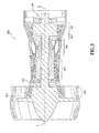
FIG. 1 illustrates cross-sectional view of an exemplary gas turbine engine, in accordance with various embodiments; -
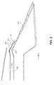
FIG. 2 illustrates a schematic cross-sectional view of an exhaust of a gas turbine engine, in accordance with various embodiments; -
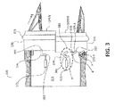
FIG. 3 illustrates a cross-sectional view of a gas turbine engine showing a portion of a cowl in an open configuration and a portion of a cowl in a closed configuration, in accordance with various embodiments; and -
FIG. 4 illustrates a cross-sectional view of a gas turbine engine showing a third stream flow corresponding to a cowl in an open configuration and a third stream flow corresponding to a cowl in a closed configuration, in accordance with various embodiments. - The detailed description of exemplary embodiments herein makes reference to the accompanying drawings, which show exemplary embodiments by way of illustration. While these exemplary embodiments are described in sufficient detail to enable those skilled in the art to practice these embodiments, it should be understood that other embodiments may be realized and that logical changes and adaptations in design and construction may be made in accordance with the present disclosure and the teachings herein. Thus, the detailed description herein is presented for purposes of illustration only and not for providing limitations on the scope of the disclosure. For example, the steps recited in any of the methods or process descriptions may be executed in any order and are not limited to the order presented.
- Furthermore, any reference to singular includes plural embodiments, and any reference to more than one component or step may include a singular embodiment or step. Also, any reference to attached, fixed, connected or the like may include permanent, removable, temporary, partial, full and/or any other possible attachment option. Additionally, any reference to without contact (or similar phrases) may also include reduced contact or minimal contact. Surface shading lines may be used throughout the figures to denote different parts but not necessarily to denote the same or different materials.
- Referring to
FIG. 1 , a gas turbine engine 100 (such as a turbofan gas turbine engine) is illustrated according to various embodiments.Gas turbine engine 100 is disposed about axial centerline axis A-A, which may also be referred to as axis of rotation A-A.Gas turbine engine 100 may comprise afan 102,compressor sections combustion section 106, andturbine sections compressor sections combustion section 106 and expanded across theturbine sections turbine sections turbine sections turbine sections compressor sections bearings 109,bearings 110 and/or the like, may support spools in thegas turbine engine 100.FIG. 1 provides a general understanding of the sections in a gas turbine engine, and is not intended to limit the disclosure. The present disclosure may extend to all types of turbine engines, including turbofan gas turbine engines and turbojet engines, for all types of applications. - The forward-aft positions of
gas turbine engine 100 lie along axis of rotation A-A. For example,fan 102 may be referred to as forward ofturbine section 107 andturbine section 107 may be referred to as aft offan 102. Typically, during operation ofgas turbine engine 100, air flows from forward to aft, for example, fromfan 102 toturbine section 107. As air flows fromfan 102 to the more aft components ofgas turbine engine 100, axis of rotation A-A may also generally define the direction of the air stream flow. It should be understood, however, that the above parameters are exemplary of various embodiments of a suitable geared architecture engine and that the present disclosure contemplates other gas turbine engines including direct drive turbofans. - In various embodiments and with reference to
FIG. 2 , exhaust from the engine core and fan of the gas turbine engine are exhausted as main nozzle flow D. Main nozzle flow D travels generally down the center line A-A of the gas turbine engine in the aft direction and is directed and/or channeled byexhaust cowl 247. A third stream flow E may be exhausted in achannel 240 that is defined outboard ofexhaust cowl 247. This third stream flow may be modulated to improve the overall efficiency of the gas turbine engine. For example, third stream flow E may be activated in response to the gas turbine engine operating in a cruise condition and/or where the fuel efficiency of the gas turbine engine can be increased, improved or optimized. Third stream flow E may be activated and/or modulated by changing the relative distance betweenexhaust cowl 247 andcowl 270.Channel 240 configured to carry third stream flow E may be defined betweenexhaust cowl 247 and the exterior surface of the nacelle of the gas turbine engine (not shown). - In various embodiments, third stream flow E may be modulated by changing the relative distance between
cowl 270 andexhaust cowl 247. In this regard,exhaust cowl 247 may comprise abump 249.Cowl 270 may comprise acorresponding bump 273. When cowl 270 is actuated from the closed position to the open position,cowl 270 may translate approximately 1.5 inches (approximately 3.81 centimeters) to approximately 4 inches (approximately 10.16 centimeters) aft. This translation is also relative toexhaust cowl 247 and/or a static structure of the gas turbine engine. The translation ofcowl 270 from the closed position to the open position allowscowl 270 and, more particularly,inner surface 271 ofcowl 270 to translate aft and move away frombump 249. This allowschannel 240 carrying third stream flow E to open and third stream flow E to exhaust aft. Moreover, bump 273 may be translated aft to define a substantially uniform flow path. In this regard, the distance betweenbump 249 and bump 273 may be substantially similar to distance between the upstreamwalls defining channel 240. - In various embodiments and with reference to
FIG. 3 ,cowl 370 is depicted in both an open and closed configuration (as labeled inFIG. 3 ).Cowl 370 may be actuated between the open and closed configurations via anactuation system 371.Actuation system 371 may comprise anactuator 372 and abell crank 374.Cowl 370 may comprise abump 373.Actuator 372 may be coupled to bell crank 374. Bell crank 374 may have afirst end 381 and asecond end 383. Bell crank 374 may also be configured to pivot between a closed position (e.g., a first position) and an open position (e.g., a second position) about a pivot point P in response to an input or load fromactuator 372. Pivot point P may be located between thefirst end 381 and thesecond end 383 ofbell crank 374. Pivot point P may be further located on diameter of gas turbine engine 320. - In various embodiments,
actuation system 371 may further comprise a plurality of guide arms 375, shown as guide arm 375-1 and guide arm 375-2 inFIG. 3 . Guide arms 375 may have a pivot point P that is circumferentially aligned with the pivot point P ofbell crank 374. In this regard, the one or more pivot points P associated with the guide arms 375 and/or bell crank 374 may be located along substantially the same diameter of gas turbine engine 320. - In various embodiments, bell crank 374 may have an angled configuration. For example, bell crank may have an angle such that is configured to cause a determined or known amount of axial motion (e.g., motion along axis A-A of
gas turbine engine 100 as shown inFIG. 1 ) and circumferential motion (e.g., circular motion about axis A-A ofgas turbine engine 100 as shown inFIG. 1 ). In this regard, the motion of the bell crank 374 about pivot point P in response to a load fromactuator 372 may causecowl 370 to translate both axially and circumferentially. The total axial translation ofcowl 370 between the closed position and the open position may be approximately 1.5 inches (approximately 3.81 centimeters) to approximately 4 inches (approximately 10.16 centimeters). However, the total distance of translation may be any suitable distance based on the overall geometry of the gas turbine engine 320 where thecowl 370 andactuation system 371 are being implemented. Moreover, the total circumferential translation may be between approximately 20 degrees and approximately 35 degrees. However, like the axial translation, the circumferential translation may be any suitable circumferential translation depending on the geometry of gas turbine engine 320,cowl 370, and/oractuation system 371. - In various embodiments, one or more guide arms 375 may be substantially straight. Guide arms 375 may comprise first ends 385 and second ends 387. First ends 385 may be separately coupled to various pivot points P along a diameter of gas turbine engine 320, as discussed herein. Second ends 387 of guide arms 375 may be coupled to cowl 370 (e.g., a common structure). Guide arms 375 may be configured to translate
cowl 370 circumferentially and axially in a manner that is consistent withbell crank 374. In this regard, the pivot points of bell crank 374 and guide arms 375 may be commonly aligned along a diameter associated with gas turbine engine 320 so that the path of translation ofcowl 370 by bell crank 374 and guide arms 375 is substantially uniform and/or consistent. - In various embodiments,
actuation system 371 may comprise asingle actuator 372.Actuation system 371 may also comprise multiple actuators depending on the load requirements to translatecowl 370 and the overall envelope and space available for installation of actuators. In this regard, in a configuration with oneactuator 372, the overall weight ofactuation system 371 may be reduced when compared to a typical cowl actuation system. Moreover, in a single actuator installation theactuator 372 ofactuation system 371 may be located at any point around the diameter of gas turbine engine 320. - In various embodiments and with reference to
FIG. 4 ,gas turbine engine 420 and, more specifically, cowl 470 (shown and labeled in cross-section inFIG. 4 ) is shown in an open configuration and a closed configuration as labeled. In the closed configuration,cowl 470 is translated forward such that an interior surface ofcowl 470 contacts bump 449 ofexhaust cowl 447. In the open configuration,cowl 470 may be translated aft causing the interior surface ofcowl 470 to translate away frombump 449. In this regard,channel 440 is defined betweencowl 470 andexhaust cowl 447 and/or gas turbine engine static structure 412 (e.g., the turbine case) allowing third stream flow E to translate aft betweenexhaust cowl 447 andcowl 470. Moreover,cowl 470 comprises abump 473 with a geometry that corresponds to bump 449. As such, whencowl 470 is translated aft,bump 473 aligns withbump 449 definingchannel 440 as a uniform flow channel for third stream flow E. Moreover, third stream flow E may be open or closed regardless of and/or independently of the position (e.g., open or closed) of the main nozzle of the gas turbine engine. - In various embodiments, the cowl actuation systems defined herein may be used in any suitable application and/or on any suitable engine. Moreover, the cowl actuation systems defined herein may be used to modulate any cowl and control and/or modulate any flow. More specifically, the systems and methods described herein may be described in the context of modulating third stream flow. However, it should be understood that the cowl actuation systems described herein may be used to modulate any cowl and/or any corresponding flow.
- Benefits and advantages have been described herein with regard to specific embodiments. Furthermore, the connecting lines shown in the various figures contained herein are intended to represent exemplary functional relationships and/or physical couplings between the various elements. It should be noted that many alternative or additional functional relationships or physical connections may be present in a practical system. However, such benefits, advantages, and any elements that may cause any benefit or advantage to occur or become more pronounced are not to be construed as critical, required, or essential features or elements of the disclosure. Reference to an element in the singular is not intended to mean "one and only one" unless explicitly so stated, but rather "one or more." Moreover, where a phrase similar to "at least one of A, B, or C" is used in the claims, it is intended that the phrase be interpreted to mean that A alone may be present in an embodiment, B alone may be present in an embodiment, C alone may be present in an embodiment, or that any combination of the elements A, B and C may be present in a single embodiment; for example, A and B, A and C, B and C, or A and B and C.
- Systems, methods and apparatus are provided herein. In the detailed description herein, references to "various embodiments", "one embodiment", "an embodiment", "an example embodiment", etc., indicate that the embodiment described may include a particular feature, structure, or characteristic, but every embodiment may not necessarily include the particular feature, structure, or characteristic. Moreover, such phrases are not necessarily referring to the same embodiment. Further, when a particular feature, structure, or characteristic is described in connection with an embodiment, it is submitted that it is within the knowledge of one skilled in the art to affect such feature, structure, or characteristic in connection with other embodiments whether or not explicitly described. After reading the description, it will be apparent to one skilled in the relevant art(s) how to implement the disclosure in alternative embodiments.
Claims (14)
- An actuation system (371), comprising:an actuator (372);a bell crank (374) operatively coupled to the actuator (372), the bell crank (374) configured to pivot about a first point, the first point located along a diameter; anda guide arm (375) having a first end (385) and a second end (387), the first end (385) configured to pivot about a second point, wherein the second point is located along the diameter.
- The actuation system of claim 1, wherein the bell crank (374) and the guide arm (375) are operatively coupled to a cowl (247,270;370;447,470).
- The actuation system of claim 2, wherein the cowl (247,270;370;447,470) is configured to translate from a closed position to an open position.
- The actuation system of claim 2 or 3, wherein the cowl (247,270;370;447,470) is an exhaust cowl (247,447) of a gas turbine engine (100;320;420).
- The actuation system of any preceding claim, wherein the bell crank (374) and the guide arm (375) are coupled to a common structure.
- The actuation system of claim 5, wherein the actuator (371) causes the bell crank (374) to pivot from a first position to a second position which also causes the guide arm (375) to actuate from a third position to a fourth position.
- The actuation system of claim 6, wherein the common structure moves axially and circumferentially in response to the bell crank (374) pivoting between the first position and the second position.
- A gas turbine engine (100;320;420), comprising:a fan (102) configured to create a fan flow;a compressor (104,105) configured to compress gas;a combustor (106) in fluid communication with the compressor (104,105);a turbine (107,108) in fluid communication with the combustor (106), the turbine (107,108) configured to drive the fan (102);an exhaust configured to direct a fan flow and the exhaust flow from the turbine (107,108);a cowl (247,270;370;447,470) configured to modulate at least a portion of the exhaust; anda cowl actuation system (371) coupled to the cowl (247,270;370;447,470) and comprising:an actuator (372) configured to modulate the cowl (247,270;370;447,470);a bell crank (374) having a first end (381) and a second end (383), the first end (381) operatively coupled to the actuator (372) and the second end (383) operatively coupled to the cowl (247,270;370;447,470), the bell crank (374) configured to pivot about a first point located between the first end (385) and the second end (387), the first point located along a diameter; anda guide arm (375) having a third end (385) and a fourth end (387), the third end (385) mounted to a second point and the fourth end (387) operatively coupled to the cowl (247,270;370;447,470), wherein the second point is located along the diameter.
- A cowl actuation system (371), comprising:a cowl (247,270;370;447,470) configured to modulate at least a portion of the exhaust flow of a gas turbine engine (100;320;420);an actuator (372);a bell crank (374) having a first end (381) and a second end (383), the first end (381) operatively coupled to the actuator (372) and the second end (383) operatively coupled to the cowl (247,270;370;447,470), the bell crank (374) configured to pivot about a first point located between the first end (381) and the second end (383), the first point located along a diameter; anda guide arm (375) having a third end (385) and a fourth end (387), the third end (385) mounted to a second point and the fourth end (387) operatively coupled to the cowl (247,270;370;447,470), wherein the second point is located along the diameter.
- The actuation system, gas turbine engine or cowl actuation system of any of claims 2 to 9, wherein the cowl (247; 270; 370; 447; 470) is configured to translate circumferentially and axially.
- The actuation system, gas turbine engine or cowl actuation system of claim 10, wherein the cowl (247,270;370;447,470) is actuated from a closed position to an open position to control a third stream flow (E) and in response to the actuator (372) pivoting the bell crank (374) from a first position to a second position.
- The actuation system, gas turbine engine or cowl actuation system of claim 10 or 11, wherein the cowl (247,270;370;447,470) defines a first bump (273;373;473) and wherein a static structure (412) of the gas turbine engine (100;320;420) defines a second bump (249;449).
- The actuation system of claim 12, wherein where the cowl (247,270;370;447,470) is in a/the open position the first bump (273;373;473) is spaced relative to the second bump (249;449) to provide a flow path that is substantially uniform.
- The actuation system of claim 12 or 13, wherein an interior surface of the cowl (247,270;370;447,470) is configured to contact the second bump (249;449) to seal a/the flow path.
Applications Claiming Priority (1)
| Application Number | Priority Date | Filing Date | Title |
|---|---|---|---|
| US14/600,824 US10371089B2 (en) | 2015-01-20 | 2015-01-20 | System for actuating an exhaust cowl |
Publications (1)
| Publication Number | Publication Date |
|---|---|
| EP3048289A1 true EP3048289A1 (en) | 2016-07-27 |
Family
ID=54548050
Family Applications (1)
| Application Number | Title | Priority Date | Filing Date |
|---|---|---|---|
| EP15194546.6A Withdrawn EP3048289A1 (en) | 2015-01-20 | 2015-11-13 | System for actuating an exhaust cowl |
Country Status (2)
| Country | Link |
|---|---|
| US (1) | US10371089B2 (en) |
| EP (1) | EP3048289A1 (en) |
Families Citing this family (2)
| Publication number | Priority date | Publication date | Assignee | Title |
|---|---|---|---|---|
| FR3075760B1 (en) * | 2017-12-21 | 2020-01-31 | Safran Nacelles | AIRCRAFT ENGINE PLATFORM |
| US12065937B1 (en) * | 2023-12-22 | 2024-08-20 | Rtx Corporation | Variable area nozzle assembly for an aircraft propulsion system |
Citations (6)
| Publication number | Priority date | Publication date | Assignee | Title |
|---|---|---|---|---|
| US2811831A (en) * | 1951-06-29 | 1957-11-05 | United Aircraft Corp | Variable area nozzle |
| US4043509A (en) * | 1976-05-13 | 1977-08-23 | General Electric Company | Actuation system for a gas turbine engine exhaust device |
| US5694767A (en) * | 1981-11-02 | 1997-12-09 | General Electric Company | Variable slot bypass injector system |
| EP1619376A2 (en) * | 2004-07-23 | 2006-01-25 | General Electric Company | Split shroud exhaust nozzle |
| US20100162684A1 (en) * | 2008-12-26 | 2010-07-01 | Von David Baker | Aircraft nozzle |
| WO2013192063A1 (en) * | 2012-06-20 | 2013-12-27 | United Technologies Corporation | Four bar drive mechanism for bleed system |
Family Cites Families (13)
| Publication number | Priority date | Publication date | Assignee | Title |
|---|---|---|---|---|
| US3289946A (en) * | 1963-08-07 | 1966-12-06 | Gen Electric | Annular convergent-divergent exhaust nozzle |
| GB1008322A (en) * | 1964-08-04 | 1965-10-27 | Rolls Royce | Gas turbine engine |
| US3598318A (en) * | 1970-04-10 | 1971-08-10 | Boeing Co | Movable acoustic splitter for nozzle area control and thrust reversal |
| CA1020365A (en) * | 1974-02-25 | 1977-11-08 | James E. Johnson | Modulating bypass variable cycle turbofan engine |
| US5261227A (en) * | 1992-11-24 | 1993-11-16 | General Electric Company | Variable specific thrust turbofan engine |
| DE69918531T2 (en) * | 1999-05-13 | 2005-08-18 | Industria De Turbo Propulsores S.A., Zamudio | Adjustment device for the outlet cross-section of a convergent-divergent exhaust nozzle |
| DE602006019925D1 (en) * | 2006-10-12 | 2011-03-10 | United Technologies Corp | TRANSLATORALLY MOVABLE INTERNAL HOOD WITH AERODYNAMIC FLAP SECTIONS |
| US7775032B2 (en) * | 2006-12-27 | 2010-08-17 | General Electric Company | Method of operating an exhaust nozzle assembly |
| US9010126B2 (en) * | 2008-02-20 | 2015-04-21 | United Technologies Corporation | Gas turbine engine with variable area fan nozzle bladder system |
| US8667802B2 (en) * | 2010-05-06 | 2014-03-11 | Spirit Aerosystems, Inc. | Variable fan duct nozzle translatable core/inner cowl including two overlapping portions made of different materials |
| WO2012174240A1 (en) * | 2011-06-14 | 2012-12-20 | Rolls-Royce North American Technologies, Inc. | Aircraft powerplant |
| WO2014160449A2 (en) * | 2013-03-13 | 2014-10-02 | Rolls-Royce North American Technologies, Inc. | Three stream, variable area fixed aperture nozzle with pneumatic actuation |
| US10145336B2 (en) * | 2013-10-24 | 2018-12-04 | United Technologies Corporation | Translating outer cowl flow modulation device and method |
-
2015
- 2015-01-20 US US14/600,824 patent/US10371089B2/en active Active
- 2015-11-13 EP EP15194546.6A patent/EP3048289A1/en not_active Withdrawn
Patent Citations (6)
| Publication number | Priority date | Publication date | Assignee | Title |
|---|---|---|---|---|
| US2811831A (en) * | 1951-06-29 | 1957-11-05 | United Aircraft Corp | Variable area nozzle |
| US4043509A (en) * | 1976-05-13 | 1977-08-23 | General Electric Company | Actuation system for a gas turbine engine exhaust device |
| US5694767A (en) * | 1981-11-02 | 1997-12-09 | General Electric Company | Variable slot bypass injector system |
| EP1619376A2 (en) * | 2004-07-23 | 2006-01-25 | General Electric Company | Split shroud exhaust nozzle |
| US20100162684A1 (en) * | 2008-12-26 | 2010-07-01 | Von David Baker | Aircraft nozzle |
| WO2013192063A1 (en) * | 2012-06-20 | 2013-12-27 | United Technologies Corporation | Four bar drive mechanism for bleed system |
Also Published As
| Publication number | Publication date |
|---|---|
| US10371089B2 (en) | 2019-08-06 |
| US20160208737A1 (en) | 2016-07-21 |
Similar Documents
| Publication | Publication Date | Title |
|---|---|---|
| US11092030B2 (en) | Adaptive case for a gas turbine engine | |
| US11085310B2 (en) | Variable pitch fan actuator | |
| EP2984315B1 (en) | Annular airflow actuation system for variable cycle gas turbine engines | |
| US10443412B2 (en) | Variable pitch fan pitch range limiter | |
| EP3693572B1 (en) | Power assisted engine start bleed system | |
| US10316686B2 (en) | High response turbine tip clearance control system | |
| US20160024959A1 (en) | Variable vane drive system | |
| EP3106624B1 (en) | Turbine engine tip clearance control system with rocker arms | |
| US20090067978A1 (en) | Variable area turbine vane arrangement | |
| EP3097274B1 (en) | Accessible rapid response blade tip clearance control system | |
| US9422825B2 (en) | Gas turbine engine synchronization ring | |
| US20170167438A1 (en) | Gas Turbine Engine | |
| US10060286B2 (en) | Geared annular airflow actuation system for variable cycle gas turbine engines | |
| EP3026217B1 (en) | Turbine rotor or stator segmented sideplates with anti-rotation | |
| EP3323979B1 (en) | Airfoil with panel having perimeter seal | |
| EP4242445A1 (en) | Variable area nozzle assembly | |
| EP3048289A1 (en) | System for actuating an exhaust cowl | |
| CN112443364A (en) | Actuation assembly for concentric variable stator vanes | |
| EP2952693B1 (en) | Case with vane retention feature | |
| US11970956B2 (en) | Pitch change mechanism for a fan of a gas turbine engine | |
| EP3626933B1 (en) | High pressure turbine rear side plate | |
| EP3324004A1 (en) | Airfoil with retention pocket holding airfoil piece |
Legal Events
| Date | Code | Title | Description |
|---|---|---|---|
| PUAI | Public reference made under article 153(3) epc to a published international application that has entered the european phase |
Free format text: ORIGINAL CODE: 0009012 |
|
| AK | Designated contracting states |
Kind code of ref document: A1 Designated state(s): AL AT BE BG CH CY CZ DE DK EE ES FI FR GB GR HR HU IE IS IT LI LT LU LV MC MK MT NL NO PL PT RO RS SE SI SK SM TR |
|
| AX | Request for extension of the european patent |
Extension state: BA ME |
|
| RAP1 | Party data changed (applicant data changed or rights of an application transferred) |
Owner name: UNITED TECHNOLOGIES CORPORATION |
|
| STAA | Information on the status of an ep patent application or granted ep patent |
Free format text: STATUS: REQUEST FOR EXAMINATION WAS MADE |
|
| 17P | Request for examination filed |
Effective date: 20170127 |
|
| RBV | Designated contracting states (corrected) |
Designated state(s): AL AT BE BG CH CY CZ DE DK EE ES FI FR GB GR HR HU IE IS IT LI LT LU LV MC MK MT NL NO PL PT RO RS SE SI SK SM TR |
|
| STAA | Information on the status of an ep patent application or granted ep patent |
Free format text: STATUS: EXAMINATION IS IN PROGRESS |
|
| 17Q | First examination report despatched |
Effective date: 20200128 |
|
| STAA | Information on the status of an ep patent application or granted ep patent |
Free format text: STATUS: THE APPLICATION IS DEEMED TO BE WITHDRAWN |
|
| 18D | Application deemed to be withdrawn |
Effective date: 20200808 |