EP3048260A1 - Seal for turbofan engine - Google Patents
Seal for turbofan engine Download PDFInfo
- Publication number
- EP3048260A1 EP3048260A1 EP14845489.5A EP14845489A EP3048260A1 EP 3048260 A1 EP3048260 A1 EP 3048260A1 EP 14845489 A EP14845489 A EP 14845489A EP 3048260 A1 EP3048260 A1 EP 3048260A1
- Authority
- EP
- European Patent Office
- Prior art keywords
- vane
- seal
- liner
- section
- tip
- Prior art date
- Legal status (The legal status is an assumption and is not a legal conclusion. Google has not performed a legal analysis and makes no representation as to the accuracy of the status listed.)
- Granted
Links
Images



Classifications
-
- F—MECHANICAL ENGINEERING; LIGHTING; HEATING; WEAPONS; BLASTING
- F01—MACHINES OR ENGINES IN GENERAL; ENGINE PLANTS IN GENERAL; STEAM ENGINES
- F01D—NON-POSITIVE DISPLACEMENT MACHINES OR ENGINES, e.g. STEAM TURBINES
- F01D11/00—Preventing or minimising internal leakage of working-fluid, e.g. between stages
- F01D11/005—Sealing means between non relatively rotating elements
-
- F—MECHANICAL ENGINEERING; LIGHTING; HEATING; WEAPONS; BLASTING
- F01—MACHINES OR ENGINES IN GENERAL; ENGINE PLANTS IN GENERAL; STEAM ENGINES
- F01D—NON-POSITIVE DISPLACEMENT MACHINES OR ENGINES, e.g. STEAM TURBINES
- F01D9/00—Stators
- F01D9/02—Nozzles; Nozzle boxes; Stator blades; Guide conduits, e.g. individual nozzles
- F01D9/04—Nozzles; Nozzle boxes; Stator blades; Guide conduits, e.g. individual nozzles forming ring or sector
- F01D9/041—Nozzles; Nozzle boxes; Stator blades; Guide conduits, e.g. individual nozzles forming ring or sector using blades
-
- F—MECHANICAL ENGINEERING; LIGHTING; HEATING; WEAPONS; BLASTING
- F01—MACHINES OR ENGINES IN GENERAL; ENGINE PLANTS IN GENERAL; STEAM ENGINES
- F01D—NON-POSITIVE DISPLACEMENT MACHINES OR ENGINES, e.g. STEAM TURBINES
- F01D9/00—Stators
- F01D9/02—Nozzles; Nozzle boxes; Stator blades; Guide conduits, e.g. individual nozzles
- F01D9/04—Nozzles; Nozzle boxes; Stator blades; Guide conduits, e.g. individual nozzles forming ring or sector
- F01D9/042—Nozzles; Nozzle boxes; Stator blades; Guide conduits, e.g. individual nozzles forming ring or sector fixing blades to stators
-
- F—MECHANICAL ENGINEERING; LIGHTING; HEATING; WEAPONS; BLASTING
- F02—COMBUSTION ENGINES; HOT-GAS OR COMBUSTION-PRODUCT ENGINE PLANTS
- F02K—JET-PROPULSION PLANTS
- F02K3/00—Plants including a gas turbine driving a compressor or a ducted fan
- F02K3/02—Plants including a gas turbine driving a compressor or a ducted fan in which part of the working fluid by-passes the turbine and combustion chamber
- F02K3/04—Plants including a gas turbine driving a compressor or a ducted fan in which part of the working fluid by-passes the turbine and combustion chamber the plant including ducted fans, i.e. fans with high volume, low pressure outputs, for augmenting the jet thrust, e.g. of double-flow type
-
- F—MECHANICAL ENGINEERING; LIGHTING; HEATING; WEAPONS; BLASTING
- F05—INDEXING SCHEMES RELATING TO ENGINES OR PUMPS IN VARIOUS SUBCLASSES OF CLASSES F01-F04
- F05D—INDEXING SCHEME FOR ASPECTS RELATING TO NON-POSITIVE-DISPLACEMENT MACHINES OR ENGINES, GAS-TURBINES OR JET-PROPULSION PLANTS
- F05D2220/00—Application
- F05D2220/30—Application in turbines
- F05D2220/36—Application in turbines specially adapted for the fan of turbofan engines
-
- F—MECHANICAL ENGINEERING; LIGHTING; HEATING; WEAPONS; BLASTING
- F05—INDEXING SCHEMES RELATING TO ENGINES OR PUMPS IN VARIOUS SUBCLASSES OF CLASSES F01-F04
- F05D—INDEXING SCHEME FOR ASPECTS RELATING TO NON-POSITIVE-DISPLACEMENT MACHINES OR ENGINES, GAS-TURBINES OR JET-PROPULSION PLANTS
- F05D2240/00—Components
- F05D2240/10—Stators
- F05D2240/14—Casings or housings protecting or supporting assemblies within
-
- F—MECHANICAL ENGINEERING; LIGHTING; HEATING; WEAPONS; BLASTING
- F05—INDEXING SCHEMES RELATING TO ENGINES OR PUMPS IN VARIOUS SUBCLASSES OF CLASSES F01-F04
- F05D—INDEXING SCHEME FOR ASPECTS RELATING TO NON-POSITIVE-DISPLACEMENT MACHINES OR ENGINES, GAS-TURBINES OR JET-PROPULSION PLANTS
- F05D2250/00—Geometry
- F05D2250/20—Three-dimensional
- F05D2250/29—Three-dimensional machined; miscellaneous
- F05D2250/292—Three-dimensional machined; miscellaneous tapered
-
- F—MECHANICAL ENGINEERING; LIGHTING; HEATING; WEAPONS; BLASTING
- F05—INDEXING SCHEMES RELATING TO ENGINES OR PUMPS IN VARIOUS SUBCLASSES OF CLASSES F01-F04
- F05D—INDEXING SCHEME FOR ASPECTS RELATING TO NON-POSITIVE-DISPLACEMENT MACHINES OR ENGINES, GAS-TURBINES OR JET-PROPULSION PLANTS
- F05D2300/00—Materials; Properties thereof
- F05D2300/40—Organic materials
- F05D2300/43—Synthetic polymers, e.g. plastics; Rubber
- F05D2300/431—Rubber
-
- F—MECHANICAL ENGINEERING; LIGHTING; HEATING; WEAPONS; BLASTING
- F05—INDEXING SCHEMES RELATING TO ENGINES OR PUMPS IN VARIOUS SUBCLASSES OF CLASSES F01-F04
- F05D—INDEXING SCHEME FOR ASPECTS RELATING TO NON-POSITIVE-DISPLACEMENT MACHINES OR ENGINES, GAS-TURBINES OR JET-PROPULSION PLANTS
- F05D2300/00—Materials; Properties thereof
- F05D2300/50—Intrinsic material properties or characteristics
- F05D2300/501—Elasticity
Definitions
- the present invention relates to a seal for a turbofan engine, and in particular relates to a seal for sealing a gap between a vane and a liner of an outlet guide vane.
- a turbofan engine is a jet engine of a type that has a bypass duct around an engine as a core. Part of energy generated by the engine drives a fan, part of an airflow generated by the fan is compressed by a compressor and then used for combustion in the engine while another part gushes out rearward directly through the bypass duct.
- the airflow through the bypass duct by itself produces thrust that contributes increase in engine thrust and also improves energy efficiency of the engine.
- outlet guide vanes In the bypass duct provided are outlet guide vanes.
- the outlet guide vanes are a plurality of vanes elongated in respective radial directions and such vanes are arranged circumferentially to form a circular structure.
- the airflow generated by the fan is at first whirling flow but is, after passing through the outlet guide vanes, rectified into flow going straight rearward.
- the outlet guide vanes may also function as a support that connects a fan case defining the bypass duct with the core portion, they require strength and stiffness required for such a function in addition.
- the seals in the outlet guide vanes are required to have sufficient gas-tightness.
- a vane and a liner form an angle akin to a right angle, an angular corner therebetween gives rise to cause of turbulence.
- the seals are therefore required to smoothly connect a face of the vane to a face of the liner.
- Such seals are not readily produced by any automated work but generally require laborsome processes, such as processes of building up paste-like sealing agent on objective sites by hand working, curing it and thereafter finishing it, for example.
- the present invention has been achieved in light of the aforementioned problem and, according to an aspect thereof, provides a seal capable of sealing airflow whereas this seal merely requires being attached to a liner and, along with the liner and a vane, being integrated into outlet guide vanes.
- a seal for sealing a gap between a vane and a liner of an outlet guide vane is comprised of: a joint section for joining with the liner; a flexible fillet section elongated from the joint section and tapering toward a tip so as to form a round corner between the vane and the liner when the tip is placed in contact with the vane; and a flexible rib section projecting from an inner surface and so dimensioned as to get in contact with an upper surface of an external structure for securing the vane to keep gas tightness.
- the rib section has a shape selected from the group consisting of a cylindrical column, an elliptic column, a polygonal column, and a fillet shape tapering toward a tip. More preferably, the rib section is hollow so as to facilitate elastic crush. Further preferably, the fillet section and the rib section are formed in a unitary body.
- a seal capable of sealing airflow which merely requires being attached to a liner and, along with the liner and a vane, being integrated into outlet guide vanes, is provided.
- a turbofan engine 1 is, as an example, comprised of a fan 3 at its center, and an inner wall of a nacelle 5 surrounding its circumference and a core portion 7 define a bypass duct.
- Part a of an airflow generated by the fan 3 flows into a low-pressure compressor 9 and is used by combustion in the engine but another part b thereof flows into the bypass duct.
- the part b of the airflow passing through the bypass duct is rectified by outlet guide vanes comprised of a plurality of vanes 11 and then gushes out rearward.
- each vane 11 is a plate-like structure having an airfoil shape for airflow rectification and being elongated in the radial direction. Its outer end is pinched by a support structure 13, and its inner end is pinched by a similar support structure 15, thereby being fixed to the nacelle 5 and the core portion 7.
- an outer liner 17 Adjacent to the structure 13 for fixing the outer end, having its edge in contact with a face of the vane 11, an outer liner 17 is disposed. Similarly, adjacent to the structure 15 for fixing the inner end, having its edge in contact with the face of the vane 11, an inner liner 19 is disposed. Plural combinations of the vanes 11 and the liners 17,19 are arranged circumferentially to meet side by side, thereby constituting a circular structure.
- the plurality of outer liners 17 arranged in a cylindrical shape constitutes a part of the inner wall of the nacelle 5, and the plurality of inner liners 19 similarly constitutes a part of the outer wall of the core portion.
- the outer liners 17 and the inner liners 19 thus define the bypass duct.
- a seal 21 of the present embodiment is used for sealing a gap between the inner liner 19 and the vane 11 for example.
- it may be applied to a gap between the outer liner 17 and the vane 11 or used in order to seal any other arbitrary gaps.
- An example where the seal is applied to the inner liner 19 will be described hereinafter but is of course not limiting.
- the structure 15 has a flat top face just above the inner end 11e.
- the seal 21 has its tip in contact with the surface of a face of the vane 11 and as well gets in contact with this top face, thereby sealing airflow.
- the seal 21 is combined with an end of the inner liner 19 and then used.
- the seal 21 is comprised of a joint section 23, which may have a proper structure adapted to combination with the inner liner 19.
- Such a structure may be either a proper concave-convex as shown in the drawing for the purpose of engagement or any other structure increasing contact area. Increase in contact area is advantageous for bonding the seal 21 with the inner liner 19.
- the seal 21 around its proximal end is comparable in thickness to the inner liner 19 for example but has a fillet section 27 that makes gradually thinner toward its tip.
- the seal 21 is, at least at the fillet section 27, flexible but may alternatively be totally flexible.
- an elastomer such as synthetic rubber may be applied to the seal 21.
- the fillet section 27 is so flexible to warp upward when it gets contact with the vane 11, thereby forming a round corner between the inner liner 19 and the vane 11.
- the fillet section 27 may be formed in advance to be curved upward as shown in the drawing.
- the seal 21 has a rib section 25 projecting from its inner surface.
- the rib section 25 is a projection along the lengthwise direction of the seal 21 and spans substantially its entire length.
- the rib section 25 is also flexible so as to elastically crush when it gets contact with the top face of the structure 15 for fixing the vane 11 and then comes in close contact therewith.
- the rib section 25 thus keeps gas tightness in combination with the top face of the structure 15. Proper position and dimensions are selected in the rib section 25 in accordance with the position of the top face of the structure 15 and the distance from the seal 21 to the top face of the structure 15.
- the rib section 25 and the fillet section 27 are preferably formed in a unitary body as shown in FIG. 4 . However, they may be separate bodies like as a rib 25t and a fillet 21f in a seal 21' as shown in FIG. 5 . In this case, the rib section 25t is directly joined with the inner liner 19'.
- a shape for the rib section applicable is a hollow and cylindrical column having a hole 25h in its interior in order to facilitate elastic crush, but a solid rib section 25s as shown in FIG. 6 may be also applicable.
- an elliptic column, a polygonal column, or any other proper shape may be selected.
- a fillet shape tapering toward a tip may be also applied to the rib section 25f.
- the rib section 25f may be properly warped so as to generate force pressing the fillet section 27 toward the vane 11 when it gets in contact with the structure 15.
- the seal 21 is, in a state of being combined with the inner liner 19, served for assembly.
- the fillet section 27 at its tip gets contact with the face of the vane 11 and then warps upward so as to form a round corner that is unlikely to disturb airflow.
- the fillet section 27 of the present embodiment is no exception.
- the rib section 25, however, gets in contact with the top face of the structure 15 so as to, in place of the fillet section 27, keep gas tightness.
- the seal 21 thereby successfully seals airflow in the bypass dust.
- the seal of the present embodiment does not necessitate laborsome work but only require being attached to the liner and integrated in the outlet guide vane in order to seal airflow, and also does not cause turbulence in the airflow.
- a seal that merely requires being attached to a liner and, along with the liner and a vane, being integrated into outlet guide vanes is provided.
Landscapes
- Engineering & Computer Science (AREA)
- Mechanical Engineering (AREA)
- General Engineering & Computer Science (AREA)
- Chemical & Material Sciences (AREA)
- Combustion & Propulsion (AREA)
- Structures Of Non-Positive Displacement Pumps (AREA)
- Turbine Rotor Nozzle Sealing (AREA)
Abstract
Description
- The present invention relates to a seal for a turbofan engine, and in particular relates to a seal for sealing a gap between a vane and a liner of an outlet guide vane.
- A turbofan engine is a jet engine of a type that has a bypass duct around an engine as a core. Part of energy generated by the engine drives a fan, part of an airflow generated by the fan is compressed by a compressor and then used for combustion in the engine while another part gushes out rearward directly through the bypass duct. The airflow through the bypass duct by itself produces thrust that contributes increase in engine thrust and also improves energy efficiency of the engine.
- In the bypass duct provided are outlet guide vanes. The outlet guide vanes are a plurality of vanes elongated in respective radial directions and such vanes are arranged circumferentially to form a circular structure. The airflow generated by the fan is at first whirling flow but is, after passing through the outlet guide vanes, rectified into flow going straight rearward. As the outlet guide vanes may also function as a support that connects a fan case defining the bypass duct with the core portion, they require strength and stiffness required for such a function in addition.
- Leakage of the airflow in the bypass duct to the exterior or mixture with secondary air should be avoided in view of efficiency of the fan. Therefore at any gaps between vanes and liners of the outlet guide vanes required are proper seals for sealing airflow therein.
- Related arts are disclosed in the Patent Literatures 1 and 2.
-
- PTL 1: Published
Japanese Translation of PCT Application No. 2012-511661 - PTL 2:
Japanese Patent Application Laid-open No. H10-325303 - As described above, the seals in the outlet guide vanes are required to have sufficient gas-tightness. In addition, while a vane and a liner form an angle akin to a right angle, an angular corner therebetween gives rise to cause of turbulence. The seals are therefore required to smoothly connect a face of the vane to a face of the liner. Such seals are not readily produced by any automated work but generally require laborsome processes, such as processes of building up paste-like sealing agent on objective sites by hand working, curing it and thereafter finishing it, for example.
- The present invention has been achieved in light of the aforementioned problem and, according to an aspect thereof, provides a seal capable of sealing airflow whereas this seal merely requires being attached to a liner and, along with the liner and a vane, being integrated into outlet guide vanes.
- According to an aspect of the present invention, a seal for sealing a gap between a vane and a liner of an outlet guide vane is comprised of: a joint section for joining with the liner; a flexible fillet section elongated from the joint section and tapering toward a tip so as to form a round corner between the vane and the liner when the tip is placed in contact with the vane; and a flexible rib section projecting from an inner surface and so dimensioned as to get in contact with an upper surface of an external structure for securing the vane to keep gas tightness.
- Preferably, the rib section has a shape selected from the group consisting of a cylindrical column, an elliptic column, a polygonal column, and a fillet shape tapering toward a tip. More preferably, the rib section is hollow so as to facilitate elastic crush. Further preferably, the fillet section and the rib section are formed in a unitary body.
- A seal capable of sealing airflow, which merely requires being attached to a liner and, along with the liner and a vane, being integrated into outlet guide vanes, is provided.
-
-
FIG. 1 is a schematic sectional view of a turbofan engine. -
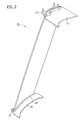
FIG. 2 is a perspective view of an outlet guide vane into which seals are integrated in accordance with an embodiment. -
FIG. 3A is a partial sectional view of the outlet guide vane, particularly showing a relation between the seal and a structure for securing the vane. -
FIG. 3B is a partial sectional view of the outlet guide vane, showing a magnified view of the seal in particular. -
FIG. 4 is a sectional view of the seal with a part of a liner. -
FIG. 5 is a sectional view of the seal in accordance with a modified example. -
FIG. 6 is a sectional view of the seal in accordance with another modified example. -
FIG. 7 is a sectional view of the seal in accordance with still another modified example. - Exemplary embodiments will be described hereinafter with reference to the appended drawings. It is particularly noted that these drawings are not always drawn to scale exactly and therefore dimensional relations among elements are not limited to those shown therein.
- Referring to
FIG. 1 , a turbofan engine 1 is, as an example, comprised of a fan 3 at its center, and an inner wall of anacelle 5 surrounding its circumference and acore portion 7 define a bypass duct. Part a of an airflow generated by the fan 3 flows into a low-pressure compressor 9 and is used by combustion in the engine but another part b thereof flows into the bypass duct. The part b of the airflow passing through the bypass duct is rectified by outlet guide vanes comprised of a plurality ofvanes 11 and then gushes out rearward. - Referring to
FIG. 2 , eachvane 11 is a plate-like structure having an airfoil shape for airflow rectification and being elongated in the radial direction. Its outer end is pinched by asupport structure 13, and its inner end is pinched by asimilar support structure 15, thereby being fixed to thenacelle 5 and thecore portion 7. - Adjacent to the
structure 13 for fixing the outer end, having its edge in contact with a face of thevane 11, anouter liner 17 is disposed. Similarly, adjacent to thestructure 15 for fixing the inner end, having its edge in contact with the face of thevane 11, aninner liner 19 is disposed. Plural combinations of thevanes 11 and theliners outer liners 17 arranged in a cylindrical shape constitutes a part of the inner wall of thenacelle 5, and the plurality ofinner liners 19 similarly constitutes a part of the outer wall of the core portion. Theouter liners 17 and theinner liners 19 thus define the bypass duct. - Referring to
FIGs. 3 in combination withFIG. 2 , aseal 21 of the present embodiment is used for sealing a gap between theinner liner 19 and thevane 11 for example. Of course it may be applied to a gap between theouter liner 17 and thevane 11 or used in order to seal any other arbitrary gaps. An example where the seal is applied to theinner liner 19 will be described hereinafter but is of course not limiting. - Referring mainly to
FIG. 3A and FIG. 3B , while theinner end 11e of thevane 11 is pinched by thestructure 15 for fixing the inner end as described above, thestructure 15 has a flat top face just above theinner end 11e. Theseal 21 has its tip in contact with the surface of a face of thevane 11 and as well gets in contact with this top face, thereby sealing airflow. - Referring to
FIG. 4 , theseal 21 is combined with an end of theinner liner 19 and then used. Theseal 21 is comprised of ajoint section 23, which may have a proper structure adapted to combination with theinner liner 19. Such a structure may be either a proper concave-convex as shown in the drawing for the purpose of engagement or any other structure increasing contact area. Increase in contact area is advantageous for bonding theseal 21 with theinner liner 19. - The
seal 21 around its proximal end is comparable in thickness to theinner liner 19 for example but has afillet section 27 that makes gradually thinner toward its tip. Theseal 21 is, at least at thefillet section 27, flexible but may alternatively be totally flexible. To give flexibility thereto, an elastomer such as synthetic rubber may be applied to theseal 21. Thefillet section 27 is so flexible to warp upward when it gets contact with thevane 11, thereby forming a round corner between theinner liner 19 and thevane 11. To make it easy to warp upward, thefillet section 27 may be formed in advance to be curved upward as shown in the drawing. - In addition, the
seal 21 has arib section 25 projecting from its inner surface. Therib section 25 is a projection along the lengthwise direction of theseal 21 and spans substantially its entire length. Therib section 25 is also flexible so as to elastically crush when it gets contact with the top face of thestructure 15 for fixing thevane 11 and then comes in close contact therewith. Therib section 25 thus keeps gas tightness in combination with the top face of thestructure 15. Proper position and dimensions are selected in therib section 25 in accordance with the position of the top face of thestructure 15 and the distance from theseal 21 to the top face of thestructure 15. - The
rib section 25 and thefillet section 27 are preferably formed in a unitary body as shown inFIG. 4 . However, they may be separate bodies like as arib 25t and a fillet 21f in a seal 21' as shown inFIG. 5 . In this case, therib section 25t is directly joined with the inner liner 19'. - To a shape for the rib section applicable is a hollow and cylindrical column having a
hole 25h in its interior in order to facilitate elastic crush, but asolid rib section 25s as shown inFIG. 6 may be also applicable. Alternatively, instead of the column, an elliptic column, a polygonal column, or any other proper shape may be selected. Still alternatively, as shown inFIG. 7 , a fillet shape tapering toward a tip may be also applied to therib section 25f. Therib section 25f may be properly warped so as to generate force pressing thefillet section 27 toward thevane 11 when it gets in contact with thestructure 15. - In any of the embodiments described above, the
seal 21 is, in a state of being combined with theinner liner 19, served for assembly. When integrated into the outlet guide vane along with theinner liner 19, thefillet section 27 at its tip gets contact with the face of thevane 11 and then warps upward so as to form a round corner that is unlikely to disturb airflow. As thevane 11 is formed in a curved surface, any structures could hardly establish gas-tight contact throughout its total length. Thefillet section 27 of the present embodiment is no exception. Therib section 25, however, gets in contact with the top face of thestructure 15 so as to, in place of thefillet section 27, keep gas tightness. Theseal 21 thereby successfully seals airflow in the bypass dust. - More specifically, the seal of the present embodiment does not necessitate laborsome work but only require being attached to the liner and integrated in the outlet guide vane in order to seal airflow, and also does not cause turbulence in the airflow.
- Although the invention has been described above by reference to certain embodiments of the invention, the invention is not limited to the embodiments described above. Modifications and variations of the embodiments described above will occur to those skilled in the art, in light of the above teachings.
- A seal that merely requires being attached to a liner and, along with the liner and a vane, being integrated into outlet guide vanes is provided.
Claims (4)
- A seal for sealing a gap between a vane and a liner of an outlet guide vane, comprising:a joint section for joining with the liner;a flexible fillet section elongated from the joint section and tapering toward a tip so as to form a round corner between the vane and the liner when the tip is placed in contact with the vane; anda flexible rib section projecting from an inner surface and so dimensioned as to get in contact with an upper surface of an external structure for securing the vane to keep gas tightness.
- The seal of claim 1, wherein the rib section comprises a shape selected from the group consisting of a cylindrical column, an elliptic column, a polygonal column, and a fillet shape tapering toward a tip.
- The seal of claim 1, wherein the rib section is hollow so as to facilitate elastic crush.
- The seal of any one of claims 1 through 3, wherein the fillet section and the rib section are formed in a unitary body.
Applications Claiming Priority (2)
| Application Number | Priority Date | Filing Date | Title |
|---|---|---|---|
| JP2013192710A JP6221544B2 (en) | 2013-09-18 | 2013-09-18 | Seal for turbofan engine |
| PCT/JP2014/073643 WO2015041083A1 (en) | 2013-09-18 | 2014-09-08 | Seal for turbofan engine |
Publications (3)
| Publication Number | Publication Date |
|---|---|
| EP3048260A1 true EP3048260A1 (en) | 2016-07-27 |
| EP3048260A4 EP3048260A4 (en) | 2017-04-19 |
| EP3048260B1 EP3048260B1 (en) | 2020-11-11 |
Family
ID=52688734
Family Applications (1)
| Application Number | Title | Priority Date | Filing Date |
|---|---|---|---|
| EP14845489.5A Active EP3048260B1 (en) | 2013-09-18 | 2014-09-08 | Seal for turbofan engine |
Country Status (7)
| Country | Link |
|---|---|
| US (1) | US10233765B2 (en) |
| EP (1) | EP3048260B1 (en) |
| JP (1) | JP6221544B2 (en) |
| CN (1) | CN105531445B (en) |
| CA (1) | CA2924425C (en) |
| RU (1) | RU2641421C2 (en) |
| WO (1) | WO2015041083A1 (en) |
Cited By (1)
| Publication number | Priority date | Publication date | Assignee | Title |
|---|---|---|---|---|
| US11738877B2 (en) | 2019-04-04 | 2023-08-29 | Rolls-Royce Plc | Seal assembly |
Families Citing this family (4)
| Publication number | Priority date | Publication date | Assignee | Title |
|---|---|---|---|---|
| US11035238B2 (en) * | 2012-06-19 | 2021-06-15 | Raytheon Technologies Corporation | Airfoil including adhesively bonded shroud |
| FR3048719B1 (en) * | 2016-03-14 | 2018-03-02 | Safran Aircraft Engines | FLOW RECTIFIER FOR TURBOMACHINE WITH INTEGRATED AND REPORTED PLATFORMS |
| FR3087831B1 (en) * | 2018-10-30 | 2022-06-24 | Safran Aircraft Engines | BLADE INCLUDING A STRUCTURE IN COMPOSITE MATERIAL AND A METAL STIFFENING PIECE |
| FR3089270B1 (en) * | 2018-11-29 | 2020-11-13 | Safran Aircraft Engines | GASKET FOR TURBOMACHINE DISCHARGE VALVE DOOR |
Family Cites Families (16)
| Publication number | Priority date | Publication date | Assignee | Title |
|---|---|---|---|---|
| FR2599081B1 (en) * | 1986-05-23 | 1988-07-29 | Snecma | MULTIFLUX TURBOJET BLOWER RECTIFIER |
| FR2600379B1 (en) * | 1986-06-18 | 1988-09-02 | Snecma | MULTIFLUX TURBOJET BLOWER RECTIFIER |
| FR2610673B1 (en) * | 1987-02-05 | 1991-03-15 | Snecma | MULTIFLUX TURBOREACTOR WITH EXTERNAL CROWN OF FREQUENCY BLOWER RECTIFIER ON THE CRANKCASE |
| GB9602129D0 (en) * | 1996-02-02 | 1996-04-03 | Rolls Royce Plc | Rotors for gas turbine engines |
| US5820338A (en) | 1997-04-24 | 1998-10-13 | United Technologies Corporation | Fan blade interplatform seal |
| US6290459B1 (en) | 1999-11-01 | 2001-09-18 | General Electric Company | Stationary flowpath components for gas turbine engines |
| US7637718B2 (en) * | 2005-09-12 | 2009-12-29 | Pratt & Whitney Canada Corp. | Vane assembly with outer grommets |
| US7628578B2 (en) | 2005-09-12 | 2009-12-08 | Pratt & Whitney Canada Corp. | Vane assembly with improved vane roots |
| GB0806171D0 (en) * | 2008-04-07 | 2008-05-14 | Rolls Royce Plc | Aeroengine fan assembly |
| US20100077612A1 (en) * | 2008-09-30 | 2010-04-01 | Courtney James Tudor | Method of manufacturing a fairing with an integrated seal |
| FR2939836B1 (en) | 2008-12-12 | 2015-05-15 | Snecma | SEAL FOR PLATFORM SEAL IN A TURBOMACHINE ROTOR |
| GB0910752D0 (en) * | 2009-06-23 | 2009-08-05 | Rolls Royce Plc | An annulus filler for a gas turbine engine |
| GB0914187D0 (en) * | 2009-08-14 | 2009-09-16 | Rolls Royce Plc | A sealing assembly |
| JP2011085056A (en) * | 2009-10-15 | 2011-04-28 | General Electric Co <Ge> | Method of manufacturing fairing seal with integrated seal |
| JP2011085055A (en) * | 2009-10-15 | 2011-04-28 | General Electric Co <Ge> | Fairing seal |
| GB2490858B (en) * | 2011-03-22 | 2014-01-01 | Rolls Royce Plc | A bladed rotor |
-
2013
- 2013-09-18 JP JP2013192710A patent/JP6221544B2/en active Active
-
2014
- 2014-09-08 WO PCT/JP2014/073643 patent/WO2015041083A1/en not_active Ceased
- 2014-09-08 CA CA2924425A patent/CA2924425C/en active Active
- 2014-09-08 CN CN201480050715.6A patent/CN105531445B/en not_active Expired - Fee Related
- 2014-09-08 RU RU2016114283A patent/RU2641421C2/en active
- 2014-09-08 EP EP14845489.5A patent/EP3048260B1/en active Active
-
2016
- 2016-03-14 US US15/068,750 patent/US10233765B2/en active Active
Non-Patent Citations (1)
| Title |
|---|
| See references of WO2015041083A1 * |
Cited By (1)
| Publication number | Priority date | Publication date | Assignee | Title |
|---|---|---|---|---|
| US11738877B2 (en) | 2019-04-04 | 2023-08-29 | Rolls-Royce Plc | Seal assembly |
Also Published As
| Publication number | Publication date |
|---|---|
| WO2015041083A1 (en) | 2015-03-26 |
| US20160194971A1 (en) | 2016-07-07 |
| EP3048260B1 (en) | 2020-11-11 |
| RU2641421C2 (en) | 2018-01-17 |
| JP6221544B2 (en) | 2017-11-01 |
| RU2016114283A (en) | 2017-10-23 |
| CN105531445B (en) | 2017-05-17 |
| CA2924425A1 (en) | 2015-03-26 |
| EP3048260A4 (en) | 2017-04-19 |
| JP2015059459A (en) | 2015-03-30 |
| CN105531445A (en) | 2016-04-27 |
| US10233765B2 (en) | 2019-03-19 |
| CA2924425C (en) | 2017-06-06 |
Similar Documents
| Publication | Publication Date | Title |
|---|---|---|
| US10233765B2 (en) | Seal for turbofan engine | |
| US20060127219A1 (en) | Seal usable between a transition and a turbine vane assembly in a turbine engine | |
| US10927689B2 (en) | Turbine vane assembly with ceramic matrix composite components mounted to case | |
| EP2836748B1 (en) | Duplex finger seal for joints with high relative displacement | |
| CA2810029C (en) | Grommet for gas turbine vane | |
| US11215062B2 (en) | Blade arrangement with damper for turbomachine | |
| KR20190089968A (en) | Rotor blades and wind turbines for wind turbines | |
| CN102536336A (en) | Turbomachine nozzle segment having integrated diaphragm | |
| US10047625B2 (en) | Fan blade root integrated sealing solution | |
| EP3026345B1 (en) | Nozzle guide with internal cooling for a gas turbine engine combustor | |
| US10550720B2 (en) | Guide vane segment | |
| US10895162B2 (en) | Guide vane segment for a turbomachine | |
| US11125095B2 (en) | Sliding seal | |
| EP3006712B1 (en) | Fan blade and fan | |
| EP3078813B1 (en) | Fan section comprising a blade platform seal with leading edge winglet and associated gas turbine engine | |
| US11746706B2 (en) | Air-sealing device intended to be inserted between an aircraft dual-flow turbine engine casing element, and a nacelle element | |
| US8474267B2 (en) | Radial turbine engine floating ring seal | |
| EP3712381B1 (en) | Inner shroud assembly for stator vanes | |
| US10190428B2 (en) | Universal seal | |
| WO2016148691A1 (en) | Shrouded turbine airfoil with knife edge seal |
Legal Events
| Date | Code | Title | Description |
|---|---|---|---|
| PUAI | Public reference made under article 153(3) epc to a published international application that has entered the european phase |
Free format text: ORIGINAL CODE: 0009012 |
|
| 17P | Request for examination filed |
Effective date: 20160331 |
|
| AK | Designated contracting states |
Kind code of ref document: A1 Designated state(s): AL AT BE BG CH CY CZ DE DK EE ES FI FR GB GR HR HU IE IS IT LI LT LU LV MC MK MT NL NO PL PT RO RS SE SI SK SM TR |
|
| AX | Request for extension of the european patent |
Extension state: BA ME |
|
| DAX | Request for extension of the european patent (deleted) | ||
| A4 | Supplementary search report drawn up and despatched |
Effective date: 20170317 |
|
| RIC1 | Information provided on ipc code assigned before grant |
Ipc: F01D 9/04 20060101ALI20170313BHEP Ipc: F01D 11/00 20060101AFI20170313BHEP Ipc: F02K 3/04 20060101ALI20170313BHEP |
|
| STAA | Information on the status of an ep patent application or granted ep patent |
Free format text: STATUS: EXAMINATION IS IN PROGRESS |
|
| 17Q | First examination report despatched |
Effective date: 20190515 |
|
| GRAP | Despatch of communication of intention to grant a patent |
Free format text: ORIGINAL CODE: EPIDOSNIGR1 |
|
| STAA | Information on the status of an ep patent application or granted ep patent |
Free format text: STATUS: GRANT OF PATENT IS INTENDED |
|
| INTG | Intention to grant announced |
Effective date: 20200513 |
|
| GRAS | Grant fee paid |
Free format text: ORIGINAL CODE: EPIDOSNIGR3 |
|
| GRAA | (expected) grant |
Free format text: ORIGINAL CODE: 0009210 |
|
| STAA | Information on the status of an ep patent application or granted ep patent |
Free format text: STATUS: THE PATENT HAS BEEN GRANTED |
|
| AK | Designated contracting states |
Kind code of ref document: B1 Designated state(s): AL AT BE BG CH CY CZ DE DK EE ES FI FR GB GR HR HU IE IS IT LI LT LU LV MC MK MT NL NO PL PT RO RS SE SI SK SM TR |
|
| REG | Reference to a national code |
Ref country code: GB Ref legal event code: FG4D |
|
| REG | Reference to a national code |
Ref country code: CH Ref legal event code: EP |
|
| REG | Reference to a national code |
Ref country code: AT Ref legal event code: REF Ref document number: 1333670 Country of ref document: AT Kind code of ref document: T Effective date: 20201115 |
|
| REG | Reference to a national code |
Ref country code: DE Ref legal event code: R096 Ref document number: 602014072340 Country of ref document: DE |
|
| REG | Reference to a national code |
Ref country code: IE Ref legal event code: FG4D |
|
| REG | Reference to a national code |
Ref country code: NL Ref legal event code: MP Effective date: 20201111 |
|
| REG | Reference to a national code |
Ref country code: AT Ref legal event code: MK05 Ref document number: 1333670 Country of ref document: AT Kind code of ref document: T Effective date: 20201111 |
|
| PG25 | Lapsed in a contracting state [announced via postgrant information from national office to epo] |
Ref country code: NO Free format text: LAPSE BECAUSE OF FAILURE TO SUBMIT A TRANSLATION OF THE DESCRIPTION OR TO PAY THE FEE WITHIN THE PRESCRIBED TIME-LIMIT Effective date: 20210211 Ref country code: PT Free format text: LAPSE BECAUSE OF FAILURE TO SUBMIT A TRANSLATION OF THE DESCRIPTION OR TO PAY THE FEE WITHIN THE PRESCRIBED TIME-LIMIT Effective date: 20210311 Ref country code: RS Free format text: LAPSE BECAUSE OF FAILURE TO SUBMIT A TRANSLATION OF THE DESCRIPTION OR TO PAY THE FEE WITHIN THE PRESCRIBED TIME-LIMIT Effective date: 20201111 Ref country code: FI Free format text: LAPSE BECAUSE OF FAILURE TO SUBMIT A TRANSLATION OF THE DESCRIPTION OR TO PAY THE FEE WITHIN THE PRESCRIBED TIME-LIMIT Effective date: 20201111 Ref country code: GR Free format text: LAPSE BECAUSE OF FAILURE TO SUBMIT A TRANSLATION OF THE DESCRIPTION OR TO PAY THE FEE WITHIN THE PRESCRIBED TIME-LIMIT Effective date: 20210212 |
|
| PG25 | Lapsed in a contracting state [announced via postgrant information from national office to epo] |
Ref country code: BG Free format text: LAPSE BECAUSE OF FAILURE TO SUBMIT A TRANSLATION OF THE DESCRIPTION OR TO PAY THE FEE WITHIN THE PRESCRIBED TIME-LIMIT Effective date: 20210211 Ref country code: AT Free format text: LAPSE BECAUSE OF FAILURE TO SUBMIT A TRANSLATION OF THE DESCRIPTION OR TO PAY THE FEE WITHIN THE PRESCRIBED TIME-LIMIT Effective date: 20201111 Ref country code: LV Free format text: LAPSE BECAUSE OF FAILURE TO SUBMIT A TRANSLATION OF THE DESCRIPTION OR TO PAY THE FEE WITHIN THE PRESCRIBED TIME-LIMIT Effective date: 20201111 Ref country code: IS Free format text: LAPSE BECAUSE OF FAILURE TO SUBMIT A TRANSLATION OF THE DESCRIPTION OR TO PAY THE FEE WITHIN THE PRESCRIBED TIME-LIMIT Effective date: 20210311 Ref country code: SE Free format text: LAPSE BECAUSE OF FAILURE TO SUBMIT A TRANSLATION OF THE DESCRIPTION OR TO PAY THE FEE WITHIN THE PRESCRIBED TIME-LIMIT Effective date: 20201111 Ref country code: PL Free format text: LAPSE BECAUSE OF FAILURE TO SUBMIT A TRANSLATION OF THE DESCRIPTION OR TO PAY THE FEE WITHIN THE PRESCRIBED TIME-LIMIT Effective date: 20201111 |
|
| REG | Reference to a national code |
Ref country code: LT Ref legal event code: MG9D |
|
| PG25 | Lapsed in a contracting state [announced via postgrant information from national office to epo] |
Ref country code: HR Free format text: LAPSE BECAUSE OF FAILURE TO SUBMIT A TRANSLATION OF THE DESCRIPTION OR TO PAY THE FEE WITHIN THE PRESCRIBED TIME-LIMIT Effective date: 20201111 |
|
| PG25 | Lapsed in a contracting state [announced via postgrant information from national office to epo] |
Ref country code: RO Free format text: LAPSE BECAUSE OF FAILURE TO SUBMIT A TRANSLATION OF THE DESCRIPTION OR TO PAY THE FEE WITHIN THE PRESCRIBED TIME-LIMIT Effective date: 20201111 Ref country code: SK Free format text: LAPSE BECAUSE OF FAILURE TO SUBMIT A TRANSLATION OF THE DESCRIPTION OR TO PAY THE FEE WITHIN THE PRESCRIBED TIME-LIMIT Effective date: 20201111 Ref country code: LT Free format text: LAPSE BECAUSE OF FAILURE TO SUBMIT A TRANSLATION OF THE DESCRIPTION OR TO PAY THE FEE WITHIN THE PRESCRIBED TIME-LIMIT Effective date: 20201111 Ref country code: SM Free format text: LAPSE BECAUSE OF FAILURE TO SUBMIT A TRANSLATION OF THE DESCRIPTION OR TO PAY THE FEE WITHIN THE PRESCRIBED TIME-LIMIT Effective date: 20201111 Ref country code: EE Free format text: LAPSE BECAUSE OF FAILURE TO SUBMIT A TRANSLATION OF THE DESCRIPTION OR TO PAY THE FEE WITHIN THE PRESCRIBED TIME-LIMIT Effective date: 20201111 Ref country code: CZ Free format text: LAPSE BECAUSE OF FAILURE TO SUBMIT A TRANSLATION OF THE DESCRIPTION OR TO PAY THE FEE WITHIN THE PRESCRIBED TIME-LIMIT Effective date: 20201111 |
|
| REG | Reference to a national code |
Ref country code: DE Ref legal event code: R097 Ref document number: 602014072340 Country of ref document: DE |
|
| PG25 | Lapsed in a contracting state [announced via postgrant information from national office to epo] |
Ref country code: DK Free format text: LAPSE BECAUSE OF FAILURE TO SUBMIT A TRANSLATION OF THE DESCRIPTION OR TO PAY THE FEE WITHIN THE PRESCRIBED TIME-LIMIT Effective date: 20201111 |
|
| PLBE | No opposition filed within time limit |
Free format text: ORIGINAL CODE: 0009261 |
|
| STAA | Information on the status of an ep patent application or granted ep patent |
Free format text: STATUS: NO OPPOSITION FILED WITHIN TIME LIMIT |
|
| 26N | No opposition filed |
Effective date: 20210812 |
|
| PG25 | Lapsed in a contracting state [announced via postgrant information from national office to epo] |
Ref country code: NL Free format text: LAPSE BECAUSE OF FAILURE TO SUBMIT A TRANSLATION OF THE DESCRIPTION OR TO PAY THE FEE WITHIN THE PRESCRIBED TIME-LIMIT Effective date: 20201111 Ref country code: AL Free format text: LAPSE BECAUSE OF FAILURE TO SUBMIT A TRANSLATION OF THE DESCRIPTION OR TO PAY THE FEE WITHIN THE PRESCRIBED TIME-LIMIT Effective date: 20201111 |
|
| PG25 | Lapsed in a contracting state [announced via postgrant information from national office to epo] |
Ref country code: SI Free format text: LAPSE BECAUSE OF FAILURE TO SUBMIT A TRANSLATION OF THE DESCRIPTION OR TO PAY THE FEE WITHIN THE PRESCRIBED TIME-LIMIT Effective date: 20201111 Ref country code: ES Free format text: LAPSE BECAUSE OF FAILURE TO SUBMIT A TRANSLATION OF THE DESCRIPTION OR TO PAY THE FEE WITHIN THE PRESCRIBED TIME-LIMIT Effective date: 20201111 |
|
| REG | Reference to a national code |
Ref country code: CH Ref legal event code: PL |
|
| REG | Reference to a national code |
Ref country code: BE Ref legal event code: MM Effective date: 20210930 |
|
| PG25 | Lapsed in a contracting state [announced via postgrant information from national office to epo] |
Ref country code: IS Free format text: LAPSE BECAUSE OF FAILURE TO SUBMIT A TRANSLATION OF THE DESCRIPTION OR TO PAY THE FEE WITHIN THE PRESCRIBED TIME-LIMIT Effective date: 20210311 Ref country code: MC Free format text: LAPSE BECAUSE OF FAILURE TO SUBMIT A TRANSLATION OF THE DESCRIPTION OR TO PAY THE FEE WITHIN THE PRESCRIBED TIME-LIMIT Effective date: 20201111 |
|
| PG25 | Lapsed in a contracting state [announced via postgrant information from national office to epo] |
Ref country code: LU Free format text: LAPSE BECAUSE OF NON-PAYMENT OF DUE FEES Effective date: 20210908 Ref country code: IE Free format text: LAPSE BECAUSE OF NON-PAYMENT OF DUE FEES Effective date: 20210908 Ref country code: BE Free format text: LAPSE BECAUSE OF NON-PAYMENT OF DUE FEES Effective date: 20210930 |
|
| PG25 | Lapsed in a contracting state [announced via postgrant information from national office to epo] |
Ref country code: LI Free format text: LAPSE BECAUSE OF NON-PAYMENT OF DUE FEES Effective date: 20210930 Ref country code: CH Free format text: LAPSE BECAUSE OF NON-PAYMENT OF DUE FEES Effective date: 20210930 |
|
| PGFP | Annual fee paid to national office [announced via postgrant information from national office to epo] |
Ref country code: IT Payment date: 20220825 Year of fee payment: 9 |
|
| PGFP | Annual fee paid to national office [announced via postgrant information from national office to epo] |
Ref country code: FR Payment date: 20220818 Year of fee payment: 9 |
|
| PG25 | Lapsed in a contracting state [announced via postgrant information from national office to epo] |
Ref country code: HU Free format text: LAPSE BECAUSE OF FAILURE TO SUBMIT A TRANSLATION OF THE DESCRIPTION OR TO PAY THE FEE WITHIN THE PRESCRIBED TIME-LIMIT; INVALID AB INITIO Effective date: 20140908 |
|
| PG25 | Lapsed in a contracting state [announced via postgrant information from national office to epo] |
Ref country code: CY Free format text: LAPSE BECAUSE OF FAILURE TO SUBMIT A TRANSLATION OF THE DESCRIPTION OR TO PAY THE FEE WITHIN THE PRESCRIBED TIME-LIMIT Effective date: 20201111 |
|
| PG25 | Lapsed in a contracting state [announced via postgrant information from national office to epo] |
Ref country code: MK Free format text: LAPSE BECAUSE OF FAILURE TO SUBMIT A TRANSLATION OF THE DESCRIPTION OR TO PAY THE FEE WITHIN THE PRESCRIBED TIME-LIMIT Effective date: 20201111 |
|
| PG25 | Lapsed in a contracting state [announced via postgrant information from national office to epo] |
Ref country code: TR Free format text: LAPSE BECAUSE OF FAILURE TO SUBMIT A TRANSLATION OF THE DESCRIPTION OR TO PAY THE FEE WITHIN THE PRESCRIBED TIME-LIMIT Effective date: 20201111 |
|
| PG25 | Lapsed in a contracting state [announced via postgrant information from national office to epo] |
Ref country code: FR Free format text: LAPSE BECAUSE OF NON-PAYMENT OF DUE FEES Effective date: 20230930 |
|
| PG25 | Lapsed in a contracting state [announced via postgrant information from national office to epo] |
Ref country code: MT Free format text: LAPSE BECAUSE OF FAILURE TO SUBMIT A TRANSLATION OF THE DESCRIPTION OR TO PAY THE FEE WITHIN THE PRESCRIBED TIME-LIMIT Effective date: 20201111 |
|
| PG25 | Lapsed in a contracting state [announced via postgrant information from national office to epo] |
Ref country code: IT Free format text: LAPSE BECAUSE OF NON-PAYMENT OF DUE FEES Effective date: 20230908 |
|
| PG25 | Lapsed in a contracting state [announced via postgrant information from national office to epo] |
Ref country code: IT Free format text: LAPSE BECAUSE OF NON-PAYMENT OF DUE FEES Effective date: 20230908 |
|
| PGFP | Annual fee paid to national office [announced via postgrant information from national office to epo] |
Ref country code: DE Payment date: 20250820 Year of fee payment: 12 |
|
| PGFP | Annual fee paid to national office [announced via postgrant information from national office to epo] |
Ref country code: GB Payment date: 20250820 Year of fee payment: 12 |