EP3048258A1 - Inner seal for a turbomachine transition piece frame assembly - Google Patents
Inner seal for a turbomachine transition piece frame assembly Download PDFInfo
- Publication number
- EP3048258A1 EP3048258A1 EP16151440.1A EP16151440A EP3048258A1 EP 3048258 A1 EP3048258 A1 EP 3048258A1 EP 16151440 A EP16151440 A EP 16151440A EP 3048258 A1 EP3048258 A1 EP 3048258A1
- Authority
- EP
- European Patent Office
- Prior art keywords
- flexible bridge
- bridge member
- frame
- transition piece
- inner seal
- Prior art date
- Legal status (The legal status is an assumption and is not a legal conclusion. Google has not performed a legal analysis and makes no representation as to the accuracy of the status listed.)
- Withdrawn
Links
- 230000007704 transition Effects 0.000 title claims abstract description 64
- 238000007789 sealing Methods 0.000 claims description 5
- 239000011248 coating agent Substances 0.000 description 12
- 238000000576 coating method Methods 0.000 description 12
- 239000007789 gas Substances 0.000 description 7
- 230000008602 contraction Effects 0.000 description 6
- 238000005299 abrasion Methods 0.000 description 3
- 239000007779 soft material Substances 0.000 description 3
- 230000004075 alteration Effects 0.000 description 1
- 239000000567 combustion gas Substances 0.000 description 1
- 238000002485 combustion reaction Methods 0.000 description 1
- 230000003137 locomotive effect Effects 0.000 description 1
- 238000006467 substitution reaction Methods 0.000 description 1
Images



Classifications
-
- F—MECHANICAL ENGINEERING; LIGHTING; HEATING; WEAPONS; BLASTING
- F01—MACHINES OR ENGINES IN GENERAL; ENGINE PLANTS IN GENERAL; STEAM ENGINES
- F01D—NON-POSITIVE DISPLACEMENT MACHINES OR ENGINES, e.g. STEAM TURBINES
- F01D11/00—Preventing or minimising internal leakage of working-fluid, e.g. between stages
-
- F—MECHANICAL ENGINEERING; LIGHTING; HEATING; WEAPONS; BLASTING
- F01—MACHINES OR ENGINES IN GENERAL; ENGINE PLANTS IN GENERAL; STEAM ENGINES
- F01D—NON-POSITIVE DISPLACEMENT MACHINES OR ENGINES, e.g. STEAM TURBINES
- F01D9/00—Stators
- F01D9/02—Nozzles; Nozzle boxes; Stator blades; Guide conduits, e.g. individual nozzles
- F01D9/023—Transition ducts between combustor cans and first stage of the turbine in gas-turbine engines; their cooling or sealings
-
- F—MECHANICAL ENGINEERING; LIGHTING; HEATING; WEAPONS; BLASTING
- F01—MACHINES OR ENGINES IN GENERAL; ENGINE PLANTS IN GENERAL; STEAM ENGINES
- F01D—NON-POSITIVE DISPLACEMENT MACHINES OR ENGINES, e.g. STEAM TURBINES
- F01D11/00—Preventing or minimising internal leakage of working-fluid, e.g. between stages
- F01D11/005—Sealing means between non relatively rotating elements
-
- F—MECHANICAL ENGINEERING; LIGHTING; HEATING; WEAPONS; BLASTING
- F02—COMBUSTION ENGINES; HOT-GAS OR COMBUSTION-PRODUCT ENGINE PLANTS
- F02C—GAS-TURBINE PLANTS; AIR INTAKES FOR JET-PROPULSION PLANTS; CONTROLLING FUEL SUPPLY IN AIR-BREATHING JET-PROPULSION PLANTS
- F02C3/00—Gas-turbine plants characterised by the use of combustion products as the working fluid
- F02C3/04—Gas-turbine plants characterised by the use of combustion products as the working fluid having a turbine driving a compressor
-
- F—MECHANICAL ENGINEERING; LIGHTING; HEATING; WEAPONS; BLASTING
- F02—COMBUSTION ENGINES; HOT-GAS OR COMBUSTION-PRODUCT ENGINE PLANTS
- F02C—GAS-TURBINE PLANTS; AIR INTAKES FOR JET-PROPULSION PLANTS; CONTROLLING FUEL SUPPLY IN AIR-BREATHING JET-PROPULSION PLANTS
- F02C7/00—Features, components parts, details or accessories, not provided for in, or of interest apart form groups F02C1/00 - F02C6/00; Air intakes for jet-propulsion plants
- F02C7/20—Mounting or supporting of plant; Accommodating heat expansion or creep
-
- F—MECHANICAL ENGINEERING; LIGHTING; HEATING; WEAPONS; BLASTING
- F02—COMBUSTION ENGINES; HOT-GAS OR COMBUSTION-PRODUCT ENGINE PLANTS
- F02C—GAS-TURBINE PLANTS; AIR INTAKES FOR JET-PROPULSION PLANTS; CONTROLLING FUEL SUPPLY IN AIR-BREATHING JET-PROPULSION PLANTS
- F02C7/00—Features, components parts, details or accessories, not provided for in, or of interest apart form groups F02C1/00 - F02C6/00; Air intakes for jet-propulsion plants
- F02C7/28—Arrangement of seals
-
- F—MECHANICAL ENGINEERING; LIGHTING; HEATING; WEAPONS; BLASTING
- F05—INDEXING SCHEMES RELATING TO ENGINES OR PUMPS IN VARIOUS SUBCLASSES OF CLASSES F01-F04
- F05D—INDEXING SCHEME FOR ASPECTS RELATING TO NON-POSITIVE-DISPLACEMENT MACHINES OR ENGINES, GAS-TURBINES OR JET-PROPULSION PLANTS
- F05D2220/00—Application
- F05D2220/30—Application in turbines
- F05D2220/32—Application in turbines in gas turbines
-
- F—MECHANICAL ENGINEERING; LIGHTING; HEATING; WEAPONS; BLASTING
- F05—INDEXING SCHEMES RELATING TO ENGINES OR PUMPS IN VARIOUS SUBCLASSES OF CLASSES F01-F04
- F05D—INDEXING SCHEME FOR ASPECTS RELATING TO NON-POSITIVE-DISPLACEMENT MACHINES OR ENGINES, GAS-TURBINES OR JET-PROPULSION PLANTS
- F05D2240/00—Components
- F05D2240/55—Seals
Definitions
- the subject matter disclosed herein relates to the art of turbomachines and, more particularly, to an inner seal for a turbomachine transition piece frame assembly.
- Turbomachine systems typically include a turbomachine coupled to an intake system and a load.
- the turbomachine typically includes a compressor portion and a turbine portion.
- An airstream passes through the intake system into the compressor portion.
- the compressor portion forms a compressed air stream that is introduced into the turbine portion.
- a portion of the compressed airstream mixes with products of combustion in a combustor assembly forming a hot gas stream that is introduced into the turbine portion through a transition piece.
- the hot gas stream flows along a hot gas path interacting with various components of the turbine portion.
- the combustor assembly includes a plurality of combustors arranged in an annular array about an inlet of the turbine portion.
- Each of the plurality of combustors is fluidically connected to the turbine portion through a corresponding one of a plurality of transition pieces.
- Each of the plurality of transition pieces includes a corresponding outlet that is linked to the turbine portion through a corresponding one of a plurality of frames.
- the plurality of frames forms an annular array about the inlet of the turbine portion.
- Each of the plurality of frames may include one or more seals that reduce leakage flow at an interface of the transition piece and the inlet of the turbine portion.
- a transition piece frame assembly includes a first frame having an inner frame member including a first end, a second end, and a first intermediate portion extending therebetween, and an outer frame member including a first end portion, a second end portion and a second intermediate portion extending therebetween.
- a first inner seal extends along the inner frame member of the first frame.
- the first inner seal includes a first end section, a second end section, and an intermediate section extending therebetween.
- a second frame includes an inner frame member having a first end, a second end, and a first intermediate portion extending therebetween, and an outer frame member including a first end portion, a second end portion and a second intermediate portion extending therebetween.
- a second inner seal extends along the inner frame member of the second frame.
- the second inner seal includes a first end section, a second end section, and an intermediate section extending therebetween.
- a flexible bridge member extends from one of the first and second end sections of the first inner seal. The flexible bridge member sealing against one of the first and second end sections of the second inner seal.
- a turbomachine includes a compressor portion, a turbine portion, a combustor assembly including one or more combustors fluidically connected to the turbine portion, and one or more transition pieces fluidically connecting each of the one or more combustors and the turbine portion.
- a transition piece frame assembly is connected to an outlet of each of the one or more transition pieces and an inlet of the turbine portion.
- the transition piece frame assembly includes a first frame coupled to one of the one or more transition pieces.
- the first frame includes an inner frame member including a first end, a second end, and a first intermediate portion extending therebetween, and an outer frame member including a first end portion, a second end portion and a second intermediate portion extending therebetween.
- a first inner seal extends along the inner frame member of the first frame.
- the seal includes a first end section, a second end section, and an intermediate section extending therebetween.
- a second frame is coupled to another of the one or more transition pieces.
- the second frame includes an inner frame member including a first end, a second end, and a first intermediate portion extending therebetween, and an outer frame member including a first end portion, a second end portion and a second intermediate portion extending therebetween.
- a second inner seal extends along the inner frame member of the second frame, the seal including a first end section, a second end section, and an intermediate section extending therebetween.
- a flexible bridge member extends from one of the first and second end sections of the first inner seal. The flexible bridge member seals against one of the first and second end sections of the second inner seal.
- Turbomachine system 1 includes a turbomachine 2 having a compressor portion 4 connected to a turbine portion 6 through a combustor assembly 8 including at least one combustor 9.
- Combustor assembly 8 may include a plurality of combustors 9 arranged in a can-annular array.
- Compressor portion 4 is also connected to turbine portion 6 via a common compressor/turbine shaft 10.
- An air inlet system 12 is fluidically connected to an inlet (not separately labeled) of compressor portion 4.
- a load, indicated generally at 14, is operatively connected to turbine portion 6.
- Load 14 may take on a variety of forms including generators, pumps, locomotive systems, and other driven loads.
- Turbine portion 6 may also be connected to an exhaust system (not shown).
- Combustor 9 includes a combustor body 30 having a combustor cap 33 and an outlet 36.
- a transition piece 45 connects combustor assembly 8 to an inlet 48 of turbine portion 6.
- Transition piece 45 includes a duct (not separately labeled) having an outlet 50 that is linked to turbine portion 6 through a transition piece frame assembly 54.
- Transition piece 45 channels combustion gases generated in combustor 9 downstream towards a first stage 58 of turbine portion 6. The hot gases expand through a hot gas path (not shown) of turbine portion 6. The hot gases interact with turbine buckets (also not shown) which rotate generating work that drives load 14.
- transition piece frame assembly 54 includes a first frame 70 and a second frame 72. At this point, it should be understood that the number of frames may vary. Typically, transition piece frame assembly 54 will include a frame for each combustor and associated transition piece.
- First frame 70 includes an inner frame member 80 and an outer frame member 82.
- Inner frame member 80 is arranged radially inwardly of outlet 50 of transition piece 45 towards a centerline of turbomachine 2.
- Outer frame member 82 is arranged radially outwardly of outlet 50 of transition piece 45.
- Inner frame member 80 includes a first end 84, a second end 85 and an intermediate portion 86 extending therebetween.
- Outer frame member 82 includes a first end portion 88, a second end portion 89 and an intermediate portion 90 extending therebetween.
- a first side frame member 93 extends between first end 84 and first end portion 88.
- a second side frame member 94 extends between second end 85 and second end portion 89.
- a first outer seal 98 extends along outer frame member 82 and a first inner seal 100 extends along inner frame member 80.
- First inner seal 100 includes a first end section 102, a second end section 103 and an intermediate section 104 extending therebetween.
- First inner seal 100 may be formed from one or more seal strips (not separately labeled) that are covered by a coating 106.
- Coating 106 may take on a variety of forms including both hard and soft materials. Coating 106 provides abrasion protection for first inner seal 100 during expansions and contractions of transition piece frame assembly 54. Of course it should be understood that first inner seal 100 may be devoid of a coating.
- Second frame 72 includes an inner frame member 108 and an outer frame member 110.
- Inner frame member 108 includes a first end 112, a second end 113, and an intermediate portion 114 extending therebetween.
- Outer frame member 110 includes a first end portion 116, a second end portion 117 and an intermediate portion 118 extending therebetween.
- a first side frame member 120 extends between first end 112 and first end portion 116.
- a second side frame member 121 extends between second end 113 and second end portion 117.
- a second outer seal 123 extends along outer frame member 110 and a second inner seal 125 extends along inner frame member 108.
- Second inner seal 125 includes a first end section 130, a second end section 131 and an intermediate section 132 extending therebetween.
- second inner seal 125 may be formed from one or more seal strips (not separately labeled) that are covered by a coating 134.
- Coating 134 may take on a variety of forms, including both hard and soft materials. Coating 134 provides abrasion protection for second inner seal 125 during expansions and contractions of transition piece frame assembly 54. Of course, it should be understood that second inner seal 125 may be devoid of a coating.
- first inner seal 100 includes a first flexible bridge member 140 arranged at second end section 103. It should be understood that another flexible bridge member (not separately labeled) may be arranged at first end section 102.
- First flexible bridge member 140 may be formed from one or more of the seal strips (not separately labeled) and includes a first end 142 and a second, cantilevered end 143.
- First flexible bridge member 140 may be covered by a coating 145 that provides abrasion protection. Coating 145 may take on a variety of forms including both hard and soft materials. Of course, it should be understood that first flexible bridge member 140 may be devoid of a coating.
- a second flexible bridge member 146 is provided at first end section 130 of second inner seal 125. It should be understood that second end section 131 of second inner seal 125 may also include a flexible bridge member (also not separately labeled).
- Second flexible bridge member 146 includes a first end 148 and a second, cantilevered end 149 as well as a recessed portion 150 that is configured to receive first flexible bridge member 140. Second flexible bridge member 146 may also be covered by a coating (not separately labeled). More specifically, first flexible bridge member 140 overlaps second flexible bridge member 146 and nests within recessed portion 150. In this manner, first and second flexible bridge members 140 and 146 may close any gaps that may exist between first and second inner seals 100 and 125. Further, by overlapping one another, first and second flexible bridge members 140 and 146 maintain contact, and thus continue to seal, during expansion and contraction of turbomachine 2 during operation.
- a first flexible bridge member 160 is arranged at second end section 103 of first inner seal 100.
- another flexible bridge member (not separately labeled) may be arranged at first end section 102.
- First flexible bridge member 160 may be formed by one or more of the seal layers (not separately labeled) and includes a first end 162 and a second, cantilevered end 163.
- a first wedge element 165 is arranged at second, cantilevered end 163.
- First wedge element 165 includes a first tapered surface 167 and an opposing, second tapered surface 168.
- First and second mechanical fasteners or pins 170 and 171 secure first wedge element 165 to first flexible bridge member 160.
- a second flexible bridge member 180 is arranged at first end section 130 of second inner seal 125.
- another flexible bridge member (not separately labeled) may be arranged at second end section 131.
- Second flexible bridge member 180 may be formed by one or more of the seal layers (not separately labeled) and includes a first end 182 and a second, cantilevered end 183.
- a second wedge element 185 is arranged at second, cantilevered end 183.
- Second wedge element 185 includes a first tapered surface 187 and an opposing, second tapered surface 188.
- First and second mechanical fasteners or pins 190 and 191 secure second wedge element 185 to second flexible bridge member 180.
- First and second wedge elements 165 and 185 overlap at corresponding ones of tapered surfaces 167 and 187.
- first and second wedge elements 165 and 185 may vary.
- first and second flexible bridge members 160 and 180 may close any gaps that may exist between first and second inner seals 100 and 125. Further, by overlapping one another, first and second wedge elements 165 and 185 maintain contact, and thus continue to seal, during expansion and contraction of turbomachine 2 during operation.
- a first flexible bridge member 200 is arranged at second end section 103 of first inner seal 100.
- another flexible bridge member (not separately labeled) may be arranged at first end section 102.
- First flexible bridge member 200 may be formed by one or more of the seal layers (not separately labeled) and includes a first end 202 and a second, cantilevered end 203.
- a first flexible coil 206 extends from second, cantilevered end 203.
- First flexible coil 206 includes a curvilinear portion 208.
- a second flexible bridge member 210 is arranged at first end section 130 of second inner seal 125.
- Second flexible bridge member 210 may be formed by one or more of the seal layers (not separately labeled) and includes a first end 212 and a second, cantilevered end 213.
- a second flexible coil 215 is arranged at second, cantilevered end 213.
- Second flexible coil 215 includes a curvilinear portion 218.
- Each inner seal may include flexible bridge members that interact with flexible bridge members on adjacent inner seals to reduce leakage on radial inner surfaces of the transition pieces.
- the flexible bridge members may interact by overlapping or, by direct contact, and maintain contact during operational phases of the turbomachine. More specifically, the flexible bridge members may accommodate expansions and contractions of various turbomachine components to maintain contact and reduce leakages.
Landscapes
- Engineering & Computer Science (AREA)
- Mechanical Engineering (AREA)
- General Engineering & Computer Science (AREA)
- Chemical & Material Sciences (AREA)
- Combustion & Propulsion (AREA)
- Turbine Rotor Nozzle Sealing (AREA)
- Gasket Seals (AREA)
- Structures Of Non-Positive Displacement Pumps (AREA)
Abstract
Description
- The subject matter disclosed herein relates to the art of turbomachines and, more particularly, to an inner seal for a turbomachine transition piece frame assembly.
- Turbomachine systems typically include a turbomachine coupled to an intake system and a load. The turbomachine typically includes a compressor portion and a turbine portion. An airstream passes through the intake system into the compressor portion. The compressor portion forms a compressed air stream that is introduced into the turbine portion. In a gas turbomachine, a portion of the compressed airstream mixes with products of combustion in a combustor assembly forming a hot gas stream that is introduced into the turbine portion through a transition piece. The hot gas stream flows along a hot gas path interacting with various components of the turbine portion.
- In certain cases, the combustor assembly includes a plurality of combustors arranged in an annular array about an inlet of the turbine portion. Each of the plurality of combustors is fluidically connected to the turbine portion through a corresponding one of a plurality of transition pieces. Each of the plurality of transition pieces includes a corresponding outlet that is linked to the turbine portion through a corresponding one of a plurality of frames. As such, the plurality of frames forms an annular array about the inlet of the turbine portion. Each of the plurality of frames may include one or more seals that reduce leakage flow at an interface of the transition piece and the inlet of the turbine portion.
- According to one aspect of an exemplary embodiment, a transition piece frame assembly includes a first frame having an inner frame member including a first end, a second end, and a first intermediate portion extending therebetween, and an outer frame member including a first end portion, a second end portion and a second intermediate portion extending therebetween. A first inner seal extends along the inner frame member of the first frame. The first inner seal includes a first end section, a second end section, and an intermediate section extending therebetween. A second frame includes an inner frame member having a first end, a second end, and a first intermediate portion extending therebetween, and an outer frame member including a first end portion, a second end portion and a second intermediate portion extending therebetween. A second inner seal extends along the inner frame member of the second frame. The second inner seal includes a first end section, a second end section, and an intermediate section extending therebetween. A flexible bridge member extends from one of the first and second end sections of the first inner seal. The flexible bridge member sealing against one of the first and second end sections of the second inner seal.
- According to another aspect of the invention a turbomachine includes a compressor portion, a turbine portion, a combustor assembly including one or more combustors fluidically connected to the turbine portion, and one or more transition pieces fluidically connecting each of the one or more combustors and the turbine portion. A transition piece frame assembly is connected to an outlet of each of the one or more transition pieces and an inlet of the turbine portion. The transition piece frame assembly includes a first frame coupled to one of the one or more transition pieces. The first frame includes an inner frame member including a first end, a second end, and a first intermediate portion extending therebetween, and an outer frame member including a first end portion, a second end portion and a second intermediate portion extending therebetween. A first inner seal extends along the inner frame member of the first frame. The seal includes a first end section, a second end section, and an intermediate section extending therebetween. A second frame is coupled to another of the one or more transition pieces. The second frame includes an inner frame member including a first end, a second end, and a first intermediate portion extending therebetween, and an outer frame member including a first end portion, a second end portion and a second intermediate portion extending therebetween. A second inner seal extends along the inner frame member of the second frame, the seal including a first end section, a second end section, and an intermediate section extending therebetween. A flexible bridge member extends from one of the first and second end sections of the first inner seal. The flexible bridge member seals against one of the first and second end sections of the second inner seal.
- These and other advantages and features will become more apparent from the following description taken in conjunction with the drawings.
- The subject matter, which is regarded as the invention, is particularly pointed out and distinctly claimed in the claims at the conclusion of the specification. The foregoing and other features, and advantages of the invention are apparent from the following detailed description taken in conjunction with the accompanying drawings in which:
-
FIG. 1 is a schematic view of a turbomachine system including a transition piece frame assembly having an inner seal, in accordance with an exemplary embodiment; -
FIG. 2 is a partial cross-sectional view a transition piece linked with a turbine portion of the turbomachine system ofFIG. 1 through the transition piece frame assembly, in accordance with an exemplary embodiment; -
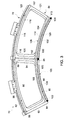
FIG. 3 is a partial plan view of the transition piece frame assembly including an inner seal, in accordance with an exemplary embodiment; -
FIG. 4 is a partial plan view of first and second inner seals, in accordance with an aspect of an exemplary embodiment; -
FIG. 5 is a partial plan view of first and second inner seals, in accordance with another aspect of an exemplary embodiment; and -
FIG. 6 is a partial plan view of first and second inner seals, in accordance with yet another aspect of an exemplary embodiment. - The detailed description explains embodiments of the invention, together with advantages and features, by way of example with reference to the drawings.
- With initial reference to
FIGs. 1 and 2 , a turbomachine system is indicated generally at 1.Turbomachine system 1 includes aturbomachine 2 having acompressor portion 4 connected to aturbine portion 6 through acombustor assembly 8 including at least onecombustor 9.Combustor assembly 8 may include a plurality ofcombustors 9 arranged in a can-annular array.Compressor portion 4 is also connected toturbine portion 6 via a common compressor/turbine shaft 10. Anair inlet system 12 is fluidically connected to an inlet (not separately labeled) ofcompressor portion 4. A load, indicated generally at 14, is operatively connected toturbine portion 6.Load 14 may take on a variety of forms including generators, pumps, locomotive systems, and other driven loads.Turbine portion 6 may also be connected to an exhaust system (not shown). - Combustor 9 includes a
combustor body 30 having acombustor cap 33 and anoutlet 36. Atransition piece 45 connectscombustor assembly 8 to aninlet 48 ofturbine portion 6.Transition piece 45 includes a duct (not separately labeled) having anoutlet 50 that is linked toturbine portion 6 through a transitionpiece frame assembly 54.Transition piece 45 channels combustion gases generated incombustor 9 downstream towards afirst stage 58 ofturbine portion 6. The hot gases expand through a hot gas path (not shown) ofturbine portion 6. The hot gases interact with turbine buckets (also not shown) which rotate generating work that drivesload 14. - As shown in
FIG. 3 , transitionpiece frame assembly 54 includes afirst frame 70 and asecond frame 72. At this point, it should be understood that the number of frames may vary. Typically, transitionpiece frame assembly 54 will include a frame for each combustor and associated transition piece.First frame 70 includes aninner frame member 80 and anouter frame member 82.Inner frame member 80 is arranged radially inwardly ofoutlet 50 oftransition piece 45 towards a centerline ofturbomachine 2.Outer frame member 82 is arranged radially outwardly ofoutlet 50 oftransition piece 45. -
Inner frame member 80 includes afirst end 84, asecond end 85 and anintermediate portion 86 extending therebetween.Outer frame member 82 includes afirst end portion 88, asecond end portion 89 and anintermediate portion 90 extending therebetween. A firstside frame member 93 extends betweenfirst end 84 andfirst end portion 88. A secondside frame member 94 extends betweensecond end 85 andsecond end portion 89. A firstouter seal 98 extends alongouter frame member 82 and a firstinner seal 100 extends alonginner frame member 80. Firstinner seal 100 includes afirst end section 102, asecond end section 103 and anintermediate section 104 extending therebetween. Firstinner seal 100 may be formed from one or more seal strips (not separately labeled) that are covered by acoating 106. Coating 106 may take on a variety of forms including both hard and soft materials. Coating 106 provides abrasion protection for firstinner seal 100 during expansions and contractions of transitionpiece frame assembly 54. Of course it should be understood that firstinner seal 100 may be devoid of a coating. -
Second frame 72 includes aninner frame member 108 and anouter frame member 110.Inner frame member 108 includes afirst end 112, asecond end 113, and anintermediate portion 114 extending therebetween.Outer frame member 110 includes afirst end portion 116, asecond end portion 117 and anintermediate portion 118 extending therebetween. A firstside frame member 120 extends betweenfirst end 112 andfirst end portion 116. A secondside frame member 121 extends betweensecond end 113 andsecond end portion 117. A secondouter seal 123 extends alongouter frame member 110 and a secondinner seal 125 extends alonginner frame member 108. Secondinner seal 125 includes afirst end section 130, asecond end section 131 and anintermediate section 132 extending therebetween. In a manner similar to that described above, secondinner seal 125 may be formed from one or more seal strips (not separately labeled) that are covered by acoating 134. Coating 134 may take on a variety of forms, including both hard and soft materials. Coating 134 provides abrasion protection for secondinner seal 125 during expansions and contractions of transitionpiece frame assembly 54. Of course, it should be understood that secondinner seal 125 may be devoid of a coating. - In accordance with an aspect of an exemplary embodiment illustrated in
FIG. 4 , firstinner seal 100 includes a firstflexible bridge member 140 arranged atsecond end section 103. It should be understood that another flexible bridge member (not separately labeled) may be arranged atfirst end section 102. Firstflexible bridge member 140 may be formed from one or more of the seal strips (not separately labeled) and includes a first end 142 and a second, cantileveredend 143. Firstflexible bridge member 140 may be covered by acoating 145 that provides abrasion protection. Coating 145 may take on a variety of forms including both hard and soft materials. Of course, it should be understood that firstflexible bridge member 140 may be devoid of a coating. A secondflexible bridge member 146 is provided atfirst end section 130 of secondinner seal 125. It should be understood thatsecond end section 131 of secondinner seal 125 may also include a flexible bridge member (also not separately labeled). - Second
flexible bridge member 146 includes afirst end 148 and a second, cantilevered end 149 as well as a recessedportion 150 that is configured to receive firstflexible bridge member 140. Secondflexible bridge member 146 may also be covered by a coating (not separately labeled). More specifically, firstflexible bridge member 140 overlaps secondflexible bridge member 146 and nests within recessedportion 150. In this manner, first and secondflexible bridge members inner seals flexible bridge members turbomachine 2 during operation. - Reference will now follow to
FIG. 5 , wherein like reference numbers represent corresponding parts in the respective views. A firstflexible bridge member 160 is arranged atsecond end section 103 of firstinner seal 100. Of course, another flexible bridge member (not separately labeled) may be arranged atfirst end section 102. Firstflexible bridge member 160 may be formed by one or more of the seal layers (not separately labeled) and includes afirst end 162 and a second, cantileveredend 163. Afirst wedge element 165 is arranged at second, cantileveredend 163.First wedge element 165 includes a firsttapered surface 167 and an opposing, secondtapered surface 168. First and second mechanical fasteners or pins 170 and 171 securefirst wedge element 165 to firstflexible bridge member 160. - A second
flexible bridge member 180 is arranged atfirst end section 130 of secondinner seal 125. Of course, another flexible bridge member (not separately labeled) may be arranged atsecond end section 131. Secondflexible bridge member 180 may be formed by one or more of the seal layers (not separately labeled) and includes afirst end 182 and a second, cantileveredend 183. Asecond wedge element 185 is arranged at second, cantileveredend 183.Second wedge element 185 includes a firsttapered surface 187 and an opposing, secondtapered surface 188. First and second mechanical fasteners or pins 190 and 191 securesecond wedge element 185 to secondflexible bridge member 180. - First and
second wedge elements surfaces second wedge elements flexible bridge members inner seals second wedge elements turbomachine 2 during operation. - Reference will now follow to
FIG. 6 , wherein like reference numbers represent corresponding parts in the respective views. A firstflexible bridge member 200 is arranged atsecond end section 103 of firstinner seal 100. Of course, another flexible bridge member (not separately labeled) may be arranged atfirst end section 102. Firstflexible bridge member 200 may be formed by one or more of the seal layers (not separately labeled) and includes afirst end 202 and a second, cantileveredend 203. A firstflexible coil 206 extends from second, cantileveredend 203. Firstflexible coil 206 includes acurvilinear portion 208. - A second
flexible bridge member 210 is arranged atfirst end section 130 of secondinner seal 125. Of course, another flexible bridge member (not separately labeled) may be arranged atsecond end section 131. Secondflexible bridge member 210 may be formed by one or more of the seal layers (not separately labeled) and includes afirst end 212 and a second, cantileveredend 213. A secondflexible coil 215 is arranged at second, cantileveredend 213. Secondflexible coil 215 includes acurvilinear portion 218. With this arrangement, first and secondflexible coils inner seals curvilinear portions flexible coils turbomachine 2 during operation. - At this point, it should be understood that the exemplary embodiments describe inner seals for a transition piece frame assembly that cooperate with one another to close gaps between adjacent transition piece frames. Each inner seal may include flexible bridge members that interact with flexible bridge members on adjacent inner seals to reduce leakage on radial inner surfaces of the transition pieces. The flexible bridge members may interact by overlapping or, by direct contact, and maintain contact during operational phases of the turbomachine. More specifically, the flexible bridge members may accommodate expansions and contractions of various turbomachine components to maintain contact and reduce leakages.
- While the invention has been described in detail in connection with only a limited number of embodiments, it should be readily understood that the invention is not limited to such disclosed embodiments. Rather, the invention can be modified to incorporate any number of variations, alterations, substitutions or equivalent arrangements not heretofore described, but which are commensurate with the spirit and scope of the invention. Additionally, while various embodiments of the invention have been described, it is to be understood that aspects of the invention may include only some of the described embodiments. Accordingly, the invention is not to be seen as limited by the foregoing description, but is only limited by the scope of the appended claims.
- Various aspects and embodiments of the present invention are defined by the following numbered clauses:
- 1. A transition piece frame assembly comprising:
- a first frame including an inner frame member including a first end, a second end, and a first intermediate portion extending therebetween, and an outer frame member including a first end portion, a second end portion and a second intermediate portion extending therebetween;
- a first inner seal extending along the inner frame member of the first frame, the seal including a first end section, a second end section, and an intermediate section extending therebetween;
- a second frame including an inner frame member including a first end, a second end, and a first intermediate portion extending therebetween, and an outer frame member including a first end portion, a second end portion and a second intermediate portion extending therebetween;
- a second inner seal extending along the inner frame member of the second frame, the seal including a first end section, a second end section, and an intermediate section extending therebetween; and
- a flexible bridge member extending from one of the first and second end sections of the first inner seal, the flexible bridge member sealing against one of the first and second end sections of the second inner seal.
- 2. The transition piece frame assembly according to
clause 1, further comprising: another flexible bridge member extending from the one of the first and second end sections of the second inner seal, the flexible bridge member and another flexible bridge member overlapping. - 3. The transition piece frame assembly according to any preceding clause, wherein one of the flexible bridge member and the other flexible bridge member includes a recessed portion.
- 4. The transition piece frame assembly according to any preceding clause, wherein the other of the flexible bridge member and the other flexible bridge member nests within the recessed portion.
- 5. The transition piece frame assembly according to any preceding clause, wherein the flexible bridge member includes a wedge element having at least one tapered surface.
- 6. The transition piece frame assembly according to any preceding clause, wherein the other flexible bridge member includes a wedge element having at least one tapered surface configured to overlap the at least one tapered surface.
- 7. The transition piece frame assembly according to any preceding clause, wherein the wedge element is secured to the one of the first and second inner seals through a fastener.
- 8. The transition piece frame assembly according to any preceding clause, wherein the flexible bridge member includes a curvilinear portion.
- 9. The transition piece frame assembly according to any preceding clause, wherein the another flexible bridge member includes a curvilinear portion configured and disposed to abut the curvilinear portion of the flexible bridge member.
- 10. The transition piece frame assembly according to any preceding clause, wherein each of the flexible bridge member and the another flexible bridge member comprise a flexible coil.
- 11. A turbomachine comprising:
- a compressor portion;
- a turbine portion;
- a combustor assembly including one or more combustors fluidically connected to the turbine portion;
- one or more transition pieces mechanically linking each of the one or more combustors and the turbine portion; and
- a transition piece frame assembly connected to an outlet of each of the one or more transition pieces and an inlet of the turbine portion, the transition piece frame assembly comprising:
- a first frame coupled to one of the one or more transition pieces, the first frame including an inner frame member including a first end, a second end, and a first intermediate portion extending therebetween, and an outer frame member including a first end portion;
- a first inner seal extending along the inner frame member of the first frame, the seal including a first end section, a second end section, and an intermediate section extending therebetween;
- a second frame coupled to another of the one or more transition pieces, the second frame including an inner frame member including a first end, a second end, and a first intermediate portion extending therebetween, and an outer frame member including a first end portion, a second end portion and a second intermediate portion extending therebetween;
- a second inner seal extending along the inner frame member of the second frame, the seal including a first end section, a second end section, and an intermediate section extending therebetween; and
- a flexible bridge member extending from one of the first and second end sections of the first inner seal, the flexible bridge member sealing against one of the first and second end sections of the second inner seal.
- 12. The turbomachine according to any preceding clause, further comprising: another flexible bridge member extending from the one of the first and second end sections of the second inner seal, the flexible bridge member and another flexible bridge member overlapping.
- 13. The turbomachine according to any preceding clause, wherein one of the flexible bridge member and the other flexible bridge member includes a recessed portion.
- 14. The turbomachine according to any preceding clause, wherein the other of the flexible bridge member and the other flexible bridge member nests within the recessed portion.
- 15. The turbomachine according to any preceding clause, wherein the flexible bridge member includes a wedge element having at least one tapered surface.
- 16. The turbomachine according to any preceding clause, wherein the other flexible bridge member includes a wedge element having at least one tapered surface configured to overlap the at least one tapered surface.
- 17. The turbomachine according to any preceding clause, wherein the wedge element is secured to the one of the first and second inner seals through a fastener.
- 18. The turbomachine according to any preceding clause, wherein the flexible bridge member includes a curvilinear portion.
- 19. The turbomachine according to any preceding clause, wherein the another flexible bridge member includes a curvilinear portion configured and disposed to abut the curvilinear portion of the flexible bridge member.
- 20. The turbomachine according to any preceding clause, wherein each of the flexible bridge member and the another flexible bridge member comprise a flexible coil.
Claims (15)
- A transition piece frame assembly (54) comprising:a first frame (70) including an inner frame member (80) including a first end (84), a second end (85), and a first intermediate portion (86) extending therebetween, and an outer frame member (82) including a first end portion (88), a second end portion (89) and a second intermediate portion (90) extending therebetween;a first inner seal (100) extending along the inner frame member (80) of the first frame (70), the seal (100) including a first end section (102), a second end section (103), and an intermediate section (104) extending therebetween;a second frame (72) including an inner frame member (108) including a first end (112), a second end (113), and a first intermediate portion (114) extending therebetween, and an outer frame member (110) including a first end portion (116), a second end portion (117) and a second intermediate portion (118) extending therebetween;a second inner seal (125) extending along the inner frame member (108) of the second frame (72), the seal (125) including a first end section (130), a second end section (131), and an intermediate section (132) extending therebetween; anda flexible bridge member (140) extending from one of the first and second end sections (102,103) of the first inner seal (100), the flexible bridge member (140) sealing against one of the first and second end sections (130,131) of the second inner seal (125).
- The transition piece frame assembly (54) according to claim 1, further comprising: another flexible bridge member (146) extending from the one of the first and second end sections (130,131) of the second inner seal (125), the flexible bridge member (140) and another flexible bridge member (146) overlapping.
- The transition piece frame assembly (54) according to claim 2, wherein one of the flexible bridge member (140) and the other flexible bridge member (146) includes a recessed portion (150).
- The transition piece frame assembly (54) according to claim 3, wherein the other of the flexible bridge member (140) and the other flexible bridge member (146) nests within the recessed portion (150).
- The transition piece frame assembly (54) according to claim 2, 3 or 4, wherein the flexible bridge member (160) includes a wedge element (165) having at least one tapered surface (167,168).
- The transition piece frame assembly (54) according to claim 5, wherein the other flexible bridge member (180) includes a wedge element (185) having at least one tapered surface (187,188) configured to overlap the at least one tapered surface (187,188).
- The transition piece frame assembly (54) according to claim 6, wherein the wedge element (185) is secured to the one of the first and second inner seals (100,125) through a fastener (190,191).
- The transition piece frame assembly (54) according to any of claims 2 to 7, wherein the flexible bridge member (200) includes a curvilinear portion (208).
- The transition piece frame assembly (54) according to claim 8, wherein the another flexible bridge member (210) includes a curvilinear portion (218) configured and disposed to abut the curvilinear portion (218) of the flexible bridge member (200).
- The transition piece frame assembly (54) according to claim 9, wherein each of the flexible bridge member (200) and the another flexible bridge member (210) comprise a flexible coil (206,215).
- A turbomachine (2) comprising:a compressor portion (4);a turbine portion (6);a combustor assembly (8) including one or more combustors (9) fluidically connected to the turbine portion (6);one or more transition pieces (45) mechanically linking each of the one or more combustors (9) and the turbine portion (6); anda transition piece frame assembly (54) connected to an outlet (50) of each of the one or more transition pieces (45) and an inlet (48) of the turbine portion (6), the transition piece frame assembly (54) comprising:a first frame (70) coupled to one of the one or more transition pieces (45), the first frame (70) including an inner frame member (80) including a first end (84), a second end (85), and a first intermediate portion (86) extending therebetween, and an outer frame member (82) including a first end portion (88);a first inner seal (100) extending along the inner frame member (80) of the first frame (70), the seal (100) including a first end section (102), a second end section (103), and an intermediate section (104) extending therebetween;a second frame (72) coupled to another of the one or more transition pieces (45), the second frame (72) including an inner frame member (108) including a first end (112), a second end (113), and a first intermediate portion (114) extending therebetween, and an outer frame member (110) including a first end portion (116), a second end portion (117) and a second intermediate portion (118) extending therebetween;a second inner seal (125) extending along the inner frame member (108) of the second frame (72), the seal (125) including a first end section (130), a second end section (131), and an intermediate section (132) extending therebetween; anda flexible bridge member (140) extending from one of the first and second end sections (102,103) of the first inner seal (100), the flexible bridge member (140) sealing against one of the first and second end sections (130,131) of the second inner seal (125).
- The turbomachine (2) according to claim 11, further comprising: another flexible bridge member (146) extending from the one of the first and second end sections (130,131) of the second inner seal (125), the flexible bridge member (140) and another flexible bridge member (146) overlapping.
- The turbomachine (2) according to claim 12, wherein one of the flexible bridge member (140) and the other flexible bridge member (146) includes a recessed portion (150).
- The turbomachine (2) according to claim 13, wherein the other of the flexible bridge member (140) and the other flexible bridge member (146) nests within the recessed portion (150).
- The turbomachine (2) according to any of claims 12 to 14, wherein the flexible bridge member (160) includes a wedge element (165) having at least one tapered surface (187,188).
Applications Claiming Priority (1)
| Application Number | Priority Date | Filing Date | Title |
|---|---|---|---|
| US14/602,899 US20160215701A1 (en) | 2015-01-22 | 2015-01-22 | Inner seal for a turbomachine transition piece frame assembly |
Publications (1)
| Publication Number | Publication Date |
|---|---|
| EP3048258A1 true EP3048258A1 (en) | 2016-07-27 |
Family
ID=55168178
Family Applications (1)
| Application Number | Title | Priority Date | Filing Date |
|---|---|---|---|
| EP16151440.1A Withdrawn EP3048258A1 (en) | 2015-01-22 | 2016-01-15 | Inner seal for a turbomachine transition piece frame assembly |
Country Status (4)
| Country | Link |
|---|---|
| US (1) | US20160215701A1 (en) |
| EP (1) | EP3048258A1 (en) |
| JP (1) | JP2016133118A (en) |
| CN (1) | CN105822357A (en) |
Cited By (1)
| Publication number | Priority date | Publication date | Assignee | Title |
|---|---|---|---|---|
| EP3299582A1 (en) * | 2016-09-26 | 2018-03-28 | General Electric Company | Sealing arrangement and gas turbine comprising a sealing arrangement |
Families Citing this family (1)
| Publication number | Priority date | Publication date | Assignee | Title |
|---|---|---|---|---|
| JP7149807B2 (en) * | 2018-11-01 | 2022-10-07 | 三菱重工業株式会社 | gas turbine combustor |
Citations (3)
| Publication number | Priority date | Publication date | Assignee | Title |
|---|---|---|---|---|
| EP1239118A2 (en) * | 2001-03-05 | 2002-09-11 | General Electric Company | Flexible cloth seal for turbine combustors |
| US20020187040A1 (en) * | 2001-06-06 | 2002-12-12 | Predmore Daniel Ross | Overlapping interference seal and methods for forming the seal |
| US20120292861A1 (en) * | 2011-05-20 | 2012-11-22 | Frank Moehrle | Turbine combustion system transition piece side seals |
Family Cites Families (3)
| Publication number | Priority date | Publication date | Assignee | Title |
|---|---|---|---|---|
| US20110146944A1 (en) * | 2009-12-22 | 2011-06-23 | John Hand | Heat Exchanger Mounting Assembly |
| US8225614B2 (en) * | 2010-10-07 | 2012-07-24 | General Electric Company | Shim for sealing transition pieces |
| US8888445B2 (en) * | 2011-08-19 | 2014-11-18 | General Electric Company | Turbomachine seal assembly |
-
2015
- 2015-01-22 US US14/602,899 patent/US20160215701A1/en not_active Abandoned
-
2016
- 2016-01-15 JP JP2016005705A patent/JP2016133118A/en active Pending
- 2016-01-15 EP EP16151440.1A patent/EP3048258A1/en not_active Withdrawn
- 2016-01-22 CN CN201610042592.2A patent/CN105822357A/en active Pending
Patent Citations (3)
| Publication number | Priority date | Publication date | Assignee | Title |
|---|---|---|---|---|
| EP1239118A2 (en) * | 2001-03-05 | 2002-09-11 | General Electric Company | Flexible cloth seal for turbine combustors |
| US20020187040A1 (en) * | 2001-06-06 | 2002-12-12 | Predmore Daniel Ross | Overlapping interference seal and methods for forming the seal |
| US20120292861A1 (en) * | 2011-05-20 | 2012-11-22 | Frank Moehrle | Turbine combustion system transition piece side seals |
Cited By (2)
| Publication number | Priority date | Publication date | Assignee | Title |
|---|---|---|---|---|
| EP3299582A1 (en) * | 2016-09-26 | 2018-03-28 | General Electric Company | Sealing arrangement and gas turbine comprising a sealing arrangement |
| US10690059B2 (en) | 2016-09-26 | 2020-06-23 | General Electric Company | Advanced seals with reduced corner leakage |
Also Published As
| Publication number | Publication date |
|---|---|
| CN105822357A (en) | 2016-08-03 |
| US20160215701A1 (en) | 2016-07-28 |
| JP2016133118A (en) | 2016-07-25 |
Similar Documents
| Publication | Publication Date | Title |
|---|---|---|
| CN111156055B (en) | Sealing system for turbine shroud segments | |
| US8225614B2 (en) | Shim for sealing transition pieces | |
| US8118548B2 (en) | Shroud for a turbomachine | |
| US9506374B2 (en) | Component of a turbine with leaf seals and method for sealing against leakage between a vane and a carrier element | |
| EP2587002B1 (en) | Turbomachine including an inner-to-outer turbine casing seal assembly and corresponding method of sealing | |
| EP2660427B1 (en) | Turbine system comprising a transition duct with a convolution seal | |
| EP3189215B1 (en) | A transition-to-turbine seal assembly | |
| US20130170994A1 (en) | Device and method for aligning tip shrouds | |
| US9771802B2 (en) | Thermal shields for gas turbine rotor | |
| EP2660428A1 (en) | Turbine system comprising a transition duct with a flexible seal | |
| CN111156054A (en) | Turbine shroud with lap seal segments | |
| EP3023594B1 (en) | Stator assembly with pad interface for a gas turbine engine | |
| EP3048258A1 (en) | Inner seal for a turbomachine transition piece frame assembly | |
| JP2019120140A (en) | Aircraft gas turbine and moving blade of aircraft gas turbine | |
| US9528392B2 (en) | System for supporting a turbine nozzle | |
| EP2653663A2 (en) | Seal for a turbine system | |
| US20140144158A1 (en) | Turbomachine component including a seal member | |
| US20130186103A1 (en) | Near flow path seal for a turbomachine | |
| CN112302730B (en) | Turbine engine with interlocking seals | |
| CN103195516B (en) | Turbomachine system and its part and the method connecting cover plates to turbomachinery components | |
| Lacy et al. | Shim for sealing transition pieces | |
| US20140037438A1 (en) | Turbine shroud for a turbomachine |
Legal Events
| Date | Code | Title | Description |
|---|---|---|---|
| PUAI | Public reference made under article 153(3) epc to a published international application that has entered the european phase |
Free format text: ORIGINAL CODE: 0009012 |
|
| AK | Designated contracting states |
Kind code of ref document: A1 Designated state(s): AL AT BE BG CH CY CZ DE DK EE ES FI FR GB GR HR HU IE IS IT LI LT LU LV MC MK MT NL NO PL PT RO RS SE SI SK SM TR |
|
| AX | Request for extension of the european patent |
Extension state: BA ME |
|
| 17P | Request for examination filed |
Effective date: 20170127 |
|
| RBV | Designated contracting states (corrected) |
Designated state(s): AL AT BE BG CH CY CZ DE DK EE ES FI FR GB GR HR HU IE IS IT LI LT LU LV MC MK MT NL NO PL PT RO RS SE SI SK SM TR |
|
| STAA | Information on the status of an ep patent application or granted ep patent |
Free format text: STATUS: THE APPLICATION IS DEEMED TO BE WITHDRAWN |
|
| 18D | Application deemed to be withdrawn |
Effective date: 20190801 |