EP3048248A1 - Rotor disk boss - Google Patents
Rotor disk boss Download PDFInfo
- Publication number
- EP3048248A1 EP3048248A1 EP16152010.1A EP16152010A EP3048248A1 EP 3048248 A1 EP3048248 A1 EP 3048248A1 EP 16152010 A EP16152010 A EP 16152010A EP 3048248 A1 EP3048248 A1 EP 3048248A1
- Authority
- EP
- European Patent Office
- Prior art keywords
- rotor disk
- boss
- disposed
- web
- disk
- Prior art date
- Legal status (The legal status is an assumption and is not a legal conclusion. Google has not performed a legal analysis and makes no representation as to the accuracy of the status listed.)
- Granted
Links
Images



Classifications
-
- F—MECHANICAL ENGINEERING; LIGHTING; HEATING; WEAPONS; BLASTING
- F01—MACHINES OR ENGINES IN GENERAL; ENGINE PLANTS IN GENERAL; STEAM ENGINES
- F01D—NON-POSITIVE DISPLACEMENT MACHINES OR ENGINES, e.g. STEAM TURBINES
- F01D5/00—Blades; Blade-carrying members; Heating, heat-insulating, cooling or antivibration means on the blades or the members
- F01D5/02—Blade-carrying members, e.g. rotors
-
- F—MECHANICAL ENGINEERING; LIGHTING; HEATING; WEAPONS; BLASTING
- F01—MACHINES OR ENGINES IN GENERAL; ENGINE PLANTS IN GENERAL; STEAM ENGINES
- F01D—NON-POSITIVE DISPLACEMENT MACHINES OR ENGINES, e.g. STEAM TURBINES
- F01D25/00—Component parts, details, or accessories, not provided for in, or of interest apart from, other groups
-
- F—MECHANICAL ENGINEERING; LIGHTING; HEATING; WEAPONS; BLASTING
- F01—MACHINES OR ENGINES IN GENERAL; ENGINE PLANTS IN GENERAL; STEAM ENGINES
- F01D—NON-POSITIVE DISPLACEMENT MACHINES OR ENGINES, e.g. STEAM TURBINES
- F01D25/00—Component parts, details, or accessories, not provided for in, or of interest apart from, other groups
- F01D25/005—Selecting particular materials
-
- F—MECHANICAL ENGINEERING; LIGHTING; HEATING; WEAPONS; BLASTING
- F01—MACHINES OR ENGINES IN GENERAL; ENGINE PLANTS IN GENERAL; STEAM ENGINES
- F01D—NON-POSITIVE DISPLACEMENT MACHINES OR ENGINES, e.g. STEAM TURBINES
- F01D5/00—Blades; Blade-carrying members; Heating, heat-insulating, cooling or antivibration means on the blades or the members
- F01D5/02—Blade-carrying members, e.g. rotors
- F01D5/022—Blade-carrying members, e.g. rotors with concentric rows of axial blades
-
- F—MECHANICAL ENGINEERING; LIGHTING; HEATING; WEAPONS; BLASTING
- F01—MACHINES OR ENGINES IN GENERAL; ENGINE PLANTS IN GENERAL; STEAM ENGINES
- F01D—NON-POSITIVE DISPLACEMENT MACHINES OR ENGINES, e.g. STEAM TURBINES
- F01D5/00—Blades; Blade-carrying members; Heating, heat-insulating, cooling or antivibration means on the blades or the members
- F01D5/02—Blade-carrying members, e.g. rotors
- F01D5/06—Rotors for more than one axial stage, e.g. of drum or multiple disc type; Details thereof, e.g. shafts, shaft connections
-
- F—MECHANICAL ENGINEERING; LIGHTING; HEATING; WEAPONS; BLASTING
- F01—MACHINES OR ENGINES IN GENERAL; ENGINE PLANTS IN GENERAL; STEAM ENGINES
- F01D—NON-POSITIVE DISPLACEMENT MACHINES OR ENGINES, e.g. STEAM TURBINES
- F01D5/00—Blades; Blade-carrying members; Heating, heat-insulating, cooling or antivibration means on the blades or the members
- F01D5/12—Blades
-
- F—MECHANICAL ENGINEERING; LIGHTING; HEATING; WEAPONS; BLASTING
- F05—INDEXING SCHEMES RELATING TO ENGINES OR PUMPS IN VARIOUS SUBCLASSES OF CLASSES F01-F04
- F05D—INDEXING SCHEME FOR ASPECTS RELATING TO NON-POSITIVE-DISPLACEMENT MACHINES OR ENGINES, GAS-TURBINES OR JET-PROPULSION PLANTS
- F05D2220/00—Application
- F05D2220/30—Application in turbines
- F05D2220/32—Application in turbines in gas turbines
-
- F—MECHANICAL ENGINEERING; LIGHTING; HEATING; WEAPONS; BLASTING
- F05—INDEXING SCHEMES RELATING TO ENGINES OR PUMPS IN VARIOUS SUBCLASSES OF CLASSES F01-F04
- F05D—INDEXING SCHEME FOR ASPECTS RELATING TO NON-POSITIVE-DISPLACEMENT MACHINES OR ENGINES, GAS-TURBINES OR JET-PROPULSION PLANTS
- F05D2230/00—Manufacture
- F05D2230/30—Manufacture with deposition of material
-
- F—MECHANICAL ENGINEERING; LIGHTING; HEATING; WEAPONS; BLASTING
- F05—INDEXING SCHEMES RELATING TO ENGINES OR PUMPS IN VARIOUS SUBCLASSES OF CLASSES F01-F04
- F05D—INDEXING SCHEME FOR ASPECTS RELATING TO NON-POSITIVE-DISPLACEMENT MACHINES OR ENGINES, GAS-TURBINES OR JET-PROPULSION PLANTS
- F05D2240/00—Components
- F05D2240/20—Rotors
- F05D2240/24—Rotors for turbines
Definitions
- the present disclosure relates to rotor disks, and more particularly, to rotor disk bosses.
- Gas turbine engines typically include a compressor section, a combustor section, and a turbine section, disposed about an axial centerline and arranged in flow series with an upstream inlet at the combustor section and a downstream exhaust at the turbine section.
- the compressor section typically includes stacked rotors across and between which air flows as it is compressed.
- Compressor sections may also include various inter-disk devices or features attached interstitially between stacked rotor disks. Inter-disk devices or features may become detached from a rotor disk during operation of the engine. Such detachment may impede the proper functioning of the gas turbine engine, may cause damage to an adjacent rotor disk, and may decrease the cycle life of rotor disks.
- a rotor disk assembly comprises a first rotor disk, wherein the first rotor disk comprises a web, disposed between a rim and a bore.
- the rotor disk assembly further comprises a second rotor disk operatively coupled to the first rotor disk, an inter-disk device disposed on the second rotor disk and extending axially toward the first rotor disk, and a boss disposed on the first rotor disk, wherein the boss protrudes axially from the web toward the inter-disk device.
- a rotor disk assembly comprises a first rotor disk operatively coupled to a second rotor disk, and a bore cavity defined by, and disposed between, the first rotor disk and the second rotor disk.
- the second rotor disk comprises a spacer arm disposed in the bore cavity and extending axially toward the first rotor disk.
- the first rotor disk comprises a boss disposed in the bore cavity and protruding axially from the first rotor disk toward the second rotor disk, whereby the boss forms a buffer between the spacer arm and the first rotor disk.
- the present disclosure provides methods for designing a rotor disk boss. Such methods may be used to determine a probable point of contact on a rotor disk in response to an inter-disk device failure, and to redesign a rotor disk to include a rotor disk boss.
- the present disclosure provides a rotor disk assembly, comprising a first rotor disk, wherein the first rotor disk comprises a web, disposed between a rim and a bore, a second rotor disk, operatively coupled to the first rotor disk, a bore cavity defined by, and disposed between, the first rotor disk and the second rotor disk, an inter-disk device, disposed at least partially in the bore cavity, a boss, disposed in the bore cavity and on the first rotor disk, wherein the boss protrudes axially from the web toward the inter-disk device, and a plurality of blades operatively coupled to the first rotor disk and the second rotor disk.
- the Applicant expressly reserves the right to claim this rotor disk assembly in the present application or a divisional thereof.
- inter-disk device may be disposed on, and operatively coupled to, the second rotor disk.
- the boss may be disposed adjacent to, and aft of, a spacer arm.
- the boss may be axially closer to the spacer arm than the rest of the web is to the spacer arm.
- the inter-disk device may comprise a plurality of air transport tubes.
- the air transport tubes may direct flowing air radially inward toward the bore.
- the boss may comprise a nickel-chromium alloy.
- a gas turbine engine may comprise this rotor disk assembly and any of its additional and/or alternative features.
- Gas turbine engine 100 (such as a turbofan gas turbine engine) is illustrated according to various embodiments.
- Gas turbine engine 100 is disposed about an axial centerline axis, which is the axis of rotation 120.
- Gas turbine engine 100 comprises a fan 140, compressor sections 150 and 160, a combustion section 180, and turbine sections 190, 191.
- the fan 140 drives air into compressor sections 150, 160, which further drive air along a core flow path for compression and communication into the combustion section 180. Air compressed in the compressor sections 150, 160 is mixed with fuel and burned in combustion section 180 and expanded across the turbine sections 190, 191.
- the turbine sections 190, 191 include high pressure rotors 192 and low pressure rotors 194, which rotate in response to the expansion.
- the turbine sections 190, 191 comprise alternating rows of rotary airfoils or blades 196 and static airfoils or vanes 198. Cooling air is supplied to the turbine sections 190, 191 from the compressor sections 150, 160.
- a plurality of bearings 115 supports spools in the gas turbine engine 100.
- the forward-aft positions of gas turbine engine 100 lie along axis of rotation 120.
- fan 140 is forward of turbine section 190 and turbine section 190 is aft of fan 140.
- the axis of rotation 120 defines the direction of the air stream flow.
- the compressor sections 150, 160 comprise a rotor disk assembly 159 and a stator assembly 157, operatively coupled to one another to create alternating rows of rotary airfoils or blades 156 and static airfoils or vanes 158.
- the rotor disk assembly 159 comprises a series of stacked rotor disks operatively coupled to one another and oriented about an axis of rotation 120.
- FIG. 1 provides a general understanding of the sections in a gas turbine engine, and is not intended to limit the disclosure.
- a rotor disk comprises a web disposed between a rim and a bore.
- the rotor disk is oriented about an axis of rotation, and the bore is disposed radially inward of the web and the rim. Because rotor disks operate at high rotational speeds and high temperatures, the web is thinner than both the rim and the bore, and connects the rim and the bore with a smooth and continuous curved surface.
- the rotor disk is coupled to a plurality of blades. Each blade is disposed on the rim of the rotor disk and extends radially outward therefrom.
- inter-disk devices are attached to a rotor disk and suspended or hung in a bore cavity defined by and disposed between stacked rotor disks.
- a plurality of air transport tubes is attached to the aft side of a forward rotor disk such that it is suspended in the bore cavity defined by the forward rotor disk and an aft rotor disk.
- an inter-disk device may become detached from the forward rotor disk and contact the aft rotor disk. Such contact may result in contact damage, galling, gouging, and the like, thereby decreasing the cycle life of the rotor disk.
- a first rotor disk 210 and a second rotor disk 260 are stacked and oriented about an axis of rotation 220, marked A-A', with A being located forward of A' and A' being located aft of A.
- the first rotor disk 210 is disposed aft of the second rotor disk 260.
- the first rotor disk 210 comprises a web 213 disposed between a rim 211 and a bore 212.
- the web 213, rim 211, and bore 212 are integral portions of the first rotor disk 210, which is in a unitary state.
- the bore 212 is disposed radially inward of the rim 211 and the web 213.
- the bore 212 abuts the web 213 at the radially inwardmost portion of the web 213, which is referred to herein as the web foot 215.
- the bore 212 is axially thicker than the web 213 so that the web foot 215 forms a filleted transition region, with opposing axial faces of the web foot 215 comprising arcuate filleted surfaces.
- the first rotor disk 210 is coupled to a plurality of blades 240. Each blade is disposed on the rim 211 of the first rotor disk 210.
- the first rotor disk 210 further comprises a boss 250 that engages an axially extending spacer arm 281 (discussed below) secured to the second rotor disk 260.
- the boss 250 is disposed between the rim 211 and the bore 212 on a forward surface of the first rotor disk 210.
- the boss 250 is axially closer to the spacer arm 281 than the rest of the web 213 is to the spacer arm 281.
- the boss 250 extends toward the spacer arm 281 in a forward axial direction from the forward surface of the first rotor disk 210.
- the boss 250 can be generally planar and/or pitched relative to the web 213.
- the boss 250 can comprise at least one arcuate surface.
- the boss 250 can be disposed radially outward of, and immediately adjacent to, the web foot 215 in various embodiments.
- a radial outer edge of the boss 250 can transition to the web 213 via a first arcuate filleted edge 231.
- the boss 250 can be disposed between the web and a first arcuate filleted surface, wherein the first arcuate filleted surface is the forward surface of the filleted transition region.
- the boss 250 can protrude axially from the web 213 at the radial outer edge of the boss 250, and can connect to the web foot 215 at a radial inner edge of the boss 250 with a smooth and continuous surface.
- the boss 250 can be disposed on the web 213 not immediately adjacent to the web foot 215.
- the boss 250 can protrude axially from the web 213 at the radial outer edge of the boss 250 and can connect to the web at the radial outer edge via a first arcuate filleted edge.
- the boss 250 can protrude axially from the web 213 at the radial inner edge of the boss 250 and can connect to the web at the radial inner edge via a second arcuate filleted edge.
- the radial-direction span of the boss 250 can be limited to the area in which the spacer arm 281 can contact the web 213.
- Various portions of the first rotor disk 210 including without limitation, the web 213 and the web foot 215, can be sensitive to contact by the spacer arm 281.
- Contact between the first rotor disk 210 and the spacer arm 281 can decrease the cycle life of the first rotor disk 210.
- the boss 250 serves as a buffer between the spacer arm 281 the web 213, and/or between the spacer arm 281 and the web foot 215.
- the boss 250 can increase the thickness of a portion of the rotor disk 210.
- the boss 250 decreases the linear distance between the spacer arm 281 and the boss 250.
- a rotor disk assembly 300 comprises a first rotor disk 210 operatively coupled to a second rotor disk 360, each of the first rotor disk 210 and the second rotor disk 360 further comprising a web 213 disposed between a rim 211 and a bore 212.
- Rotor disk assembly 300 further comprises a bore cavity 270 defined by, and disposed between, the first rotor disk 210 and the second rotor disk 360, at least one inter-disk device 280 disposed at least partially in the bore cavity 270, a boss 250 disposed in the bore cavity 270 and on the first rotor disk 210, and a plurality of blades 240 coupled to the rim 211 of the first rotor disk 210 and the second rotor disk 360.
- the rotor disk assembly 300 is oriented about an axis of rotation 220, marked A-A', with A being located forward of A' and A' being located aft of A.
- the inter-disk device 280 can comprise a plurality of air transport tubes coupled to a rotor disk by a hoop.
- the air transport tubes can be disposed in the bore cavity 270 such that air flowing radially inward from the blades will be smoothly directed toward the bores.
- the inter-disk device 280 can comprise any device disposed at least partially between rotor disks of a rotor disk assembly, and/or any means of directing air toward the bore including, without limitation, paddles or vanes.
- the inter-disk device 280 can be coupled to the second rotor disk 360 such that it is disposed in the bore cavity 270.
- the boss 250 is disposed adjacent to, and aft of, the spacer arm 281.
- the boss 250 can be disposed on the rotor disk 210 between the web 213 and the web foot 215.
- the boss 250 can increase the thickness of a portion of the first rotor disk 210.
- the boss 250 is configured to decrease the linear distance between the spacer arm 281 and the rotor disk 210.
- Inter-disk devices or features may become detached from a rotor disk during operation of the engine. Detachment of an inter-disk device and/or spacer arm from a rotor disk constitutes a failure. Upon detachment, an inter-disk device will contact a rotor disk aft of the inter-disk device at a point of contact. The point of contact is the portion of the web contacted by the spacer arm in the event of an inter-disk device failure. The point of contact may be determined experimentally, experientially, predictively, or by any other appropriate means.
- a point of contact Prior to detachment, a point of contact is calculated. With reference to FIGs. 2a and 2b , point of contact may occur at the web foot 215 and/or the web 213.
- a cycle life of the rotor disk in the event of an inter-disk device failure is determined. The cycle life may be determined through lifing analysis, review of part history, material review of the rotor disk, computer modeling, or any other suitable method. In response to an inadequate cycle life, the rotor disk may be redesigned to include a rotor disk boss.
- a method comprises determining a point of contact on a rotor disk in response to an inter-disk device failure (Step 401), determining a cycle life of the rotor disk in response to an inter-disk device failure (Step 402), and redesigning the rotor disk to include a boss (Step 403).
- the redesigning step further comprises adding material at the point of contact to create a boss (Step 404).
- the adding step causes the boss to protrude from the surface of the rotor disk in an axial direction.
- the adding step moves the point of contact in an axial direction.
- a method of designing a rotor disk further comprises improving the manufacturability of the rotor disk (Step 405).
- the improving step comprises at least one of creating a filleted transition between the boss and an adjacent web, bore or rim, decreasing the size of the boss, or decreasing the weight of the rotor disk.
Landscapes
- Engineering & Computer Science (AREA)
- Mechanical Engineering (AREA)
- General Engineering & Computer Science (AREA)
- Chemical & Material Sciences (AREA)
- Materials Engineering (AREA)
- Structures Of Non-Positive Displacement Pumps (AREA)
- Turbine Rotor Nozzle Sealing (AREA)
Abstract
Description
- The present disclosure relates to rotor disks, and more particularly, to rotor disk bosses.
- Gas turbine engines typically include a compressor section, a combustor section, and a turbine section, disposed about an axial centerline and arranged in flow series with an upstream inlet at the combustor section and a downstream exhaust at the turbine section. The compressor section typically includes stacked rotors across and between which air flows as it is compressed.
- Compressor sections may also include various inter-disk devices or features attached interstitially between stacked rotor disks. Inter-disk devices or features may become detached from a rotor disk during operation of the engine. Such detachment may impede the proper functioning of the gas turbine engine, may cause damage to an adjacent rotor disk, and may decrease the cycle life of rotor disks.
- The present disclosure provides devices related to rotor disk bosses. A rotor disk assembly comprises a first rotor disk, wherein the first rotor disk comprises a web, disposed between a rim and a bore. The rotor disk assembly further comprises a second rotor disk operatively coupled to the first rotor disk, an inter-disk device disposed on the second rotor disk and extending axially toward the first rotor disk, and a boss disposed on the first rotor disk, wherein the boss protrudes axially from the web toward the inter-disk device.
- A rotor disk assembly comprises a first rotor disk operatively coupled to a second rotor disk, and a bore cavity defined by, and disposed between, the first rotor disk and the second rotor disk. The second rotor disk comprises a spacer arm disposed in the bore cavity and extending axially toward the first rotor disk. The first rotor disk comprises a boss disposed in the bore cavity and protruding axially from the first rotor disk toward the second rotor disk, whereby the boss forms a buffer between the spacer arm and the first rotor disk.
- In various embodiments, the present disclosure provides methods for designing a rotor disk boss. Such methods may be used to determine a probable point of contact on a rotor disk in response to an inter-disk device failure, and to redesign a rotor disk to include a rotor disk boss.
- From an aspect, not presently claimed, the present disclosure provides a rotor disk assembly, comprising a first rotor disk, wherein the first rotor disk comprises a web, disposed between a rim and a bore, a second rotor disk, operatively coupled to the first rotor disk, a bore cavity defined by, and disposed between, the first rotor disk and the second rotor disk, an inter-disk device, disposed at least partially in the bore cavity, a boss, disposed in the bore cavity and on the first rotor disk, wherein the boss protrudes axially from the web toward the inter-disk device, and a plurality of blades operatively coupled to the first rotor disk and the second rotor disk. The Applicant expressly reserves the right to claim this rotor disk assembly in the present application or a divisional thereof.
- Additionally, the inter-disk device may be disposed on, and operatively coupled to, the second rotor disk.
- Additionally or alternatively, the boss may be disposed adjacent to, and aft of, a spacer arm.
- Additionally or alternatively, the boss may be axially closer to the spacer arm than the rest of the web is to the spacer arm.
- Additionally or alternatively, the inter-disk device may comprise a plurality of air transport tubes.
- Additionally or alternatively, the air transport tubes may direct flowing air radially inward toward the bore.
- Additionally or alternatively, the boss may comprise a nickel-chromium alloy.
- A gas turbine engine may comprise this rotor disk assembly and any of its additional and/or alternative features.
- The accompanying drawings are included to provide a further understanding of the present disclosure and are incorporated in, and constitute a part of, this specification, illustrate various embodiments, and together with the description, serve to explain the principles of the disclosure.
-
FIG. 1 illustrates a schematic cross-section view of a gas turbine engine in accordance with various embodiments; -
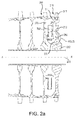
FIG. 2a illustrates a cross section view of a compressor rotor disk assembly in cross section in accordance with various embodiments; -
FIG. 2b illustrates an enlarged view of a portion ofFIG. 2a ; -
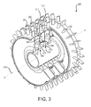
FIG. 3 illustrates a schematic cross-section view of a compressor rotor disk assembly; and -
FIG. 4 illustrates a method of designing a rotor disk and boss. - Referring to
FIG. 1 , a gas turbine engine 100 (such as a turbofan gas turbine engine) is illustrated according to various embodiments.Gas turbine engine 100 is disposed about an axial centerline axis, which is the axis ofrotation 120.Gas turbine engine 100 comprises afan 140,compressor sections combustion section 180, andturbine sections 190, 191. Thefan 140 drives air intocompressor sections combustion section 180. Air compressed in thecompressor sections combustion section 180 and expanded across theturbine sections 190, 191. Theturbine sections 190, 191 includehigh pressure rotors 192 andlow pressure rotors 194, which rotate in response to the expansion. Theturbine sections 190, 191 comprise alternating rows of rotary airfoils orblades 196 and static airfoils orvanes 198. Cooling air is supplied to theturbine sections 190, 191 from thecompressor sections bearings 115 supports spools in thegas turbine engine 100. - The forward-aft positions of
gas turbine engine 100 lie along axis ofrotation 120. For example,fan 140 is forward ofturbine section 190 andturbine section 190 is aft offan 140. During operation ofgas turbine engine 100, air flows from forward to aft, fromfan 140 toturbine section 190. As air flows fromfan 140 to the more aft components ofgas turbine engine 100, the axis ofrotation 120 defines the direction of the air stream flow. - The
compressor sections rotor disk assembly 159 and astator assembly 157, operatively coupled to one another to create alternating rows of rotary airfoils orblades 156 and static airfoils orvanes 158. Therotor disk assembly 159 comprises a series of stacked rotor disks operatively coupled to one another and oriented about an axis ofrotation 120.FIG. 1 provides a general understanding of the sections in a gas turbine engine, and is not intended to limit the disclosure. - A rotor disk comprises a web disposed between a rim and a bore. The rotor disk is oriented about an axis of rotation, and the bore is disposed radially inward of the web and the rim. Because rotor disks operate at high rotational speeds and high temperatures, the web is thinner than both the rim and the bore, and connects the rim and the bore with a smooth and continuous curved surface. The rotor disk is coupled to a plurality of blades. Each blade is disposed on the rim of the rotor disk and extends radially outward therefrom.
- Various inter-disk devices are attached to a rotor disk and suspended or hung in a bore cavity defined by and disposed between stacked rotor disks. For example, a plurality of air transport tubes is attached to the aft side of a forward rotor disk such that it is suspended in the bore cavity defined by the forward rotor disk and an aft rotor disk. During operation, an inter-disk device may become detached from the forward rotor disk and contact the aft rotor disk. Such contact may result in contact damage, galling, gouging, and the like, thereby decreasing the cycle life of the rotor disk.
- With reference to
FIGS. 2a and2b , afirst rotor disk 210 and asecond rotor disk 260 are stacked and oriented about an axis ofrotation 220, marked A-A', with A being located forward of A' and A' being located aft of A. Stated differently, thefirst rotor disk 210 is disposed aft of thesecond rotor disk 260. Thefirst rotor disk 210 comprises aweb 213 disposed between arim 211 and abore 212. Theweb 213,rim 211, and bore 212 are integral portions of thefirst rotor disk 210, which is in a unitary state. Thebore 212 is disposed radially inward of therim 211 and theweb 213. Thebore 212 abuts theweb 213 at the radially inwardmost portion of theweb 213, which is referred to herein as theweb foot 215. Thebore 212 is axially thicker than theweb 213 so that theweb foot 215 forms a filleted transition region, with opposing axial faces of theweb foot 215 comprising arcuate filleted surfaces. Thefirst rotor disk 210 is coupled to a plurality ofblades 240. Each blade is disposed on therim 211 of thefirst rotor disk 210. - The
first rotor disk 210 further comprises aboss 250 that engages an axially extending spacer arm 281 (discussed below) secured to thesecond rotor disk 260. Theboss 250 is disposed between therim 211 and thebore 212 on a forward surface of thefirst rotor disk 210. Theboss 250 is axially closer to thespacer arm 281 than the rest of theweb 213 is to thespacer arm 281. Theboss 250 extends toward thespacer arm 281 in a forward axial direction from the forward surface of thefirst rotor disk 210. In various embodiments, theboss 250 can be generally planar and/or pitched relative to theweb 213. In further embodiments, theboss 250 can comprise at least one arcuate surface. - As illustrated in
FIG. 2b , theboss 250 can be disposed radially outward of, and immediately adjacent to, theweb foot 215 in various embodiments. A radial outer edge of theboss 250 can transition to theweb 213 via a first arcuate filletededge 231. Stated differently, theboss 250 can be disposed between the web and a first arcuate filleted surface, wherein the first arcuate filleted surface is the forward surface of the filleted transition region. Theboss 250 can protrude axially from theweb 213 at the radial outer edge of theboss 250, and can connect to theweb foot 215 at a radial inner edge of theboss 250 with a smooth and continuous surface. - In further embodiments, the
boss 250 can be disposed on theweb 213 not immediately adjacent to theweb foot 215. Theboss 250 can protrude axially from theweb 213 at the radial outer edge of theboss 250 and can connect to the web at the radial outer edge via a first arcuate filleted edge. Theboss 250 can protrude axially from theweb 213 at the radial inner edge of theboss 250 and can connect to the web at the radial inner edge via a second arcuate filleted edge. - The radial-direction span of the
boss 250 can be limited to the area in which thespacer arm 281 can contact theweb 213. Various portions of thefirst rotor disk 210, including without limitation, theweb 213 and theweb foot 215, can be sensitive to contact by thespacer arm 281. Contact between thefirst rotor disk 210 and thespacer arm 281 can decrease the cycle life of thefirst rotor disk 210. Theboss 250 serves as a buffer between thespacer arm 281 theweb 213, and/or between thespacer arm 281 and theweb foot 215. Theboss 250 can increase the thickness of a portion of therotor disk 210. Theboss 250 decreases the linear distance between thespacer arm 281 and theboss 250. - With reference to
FIG. 3 , arotor disk assembly 300 comprises afirst rotor disk 210 operatively coupled to asecond rotor disk 360, each of thefirst rotor disk 210 and thesecond rotor disk 360 further comprising aweb 213 disposed between arim 211 and abore 212.Rotor disk assembly 300 further comprises abore cavity 270 defined by, and disposed between, thefirst rotor disk 210 and thesecond rotor disk 360, at least oneinter-disk device 280 disposed at least partially in thebore cavity 270, aboss 250 disposed in thebore cavity 270 and on thefirst rotor disk 210, and a plurality ofblades 240 coupled to therim 211 of thefirst rotor disk 210 and thesecond rotor disk 360. Therotor disk assembly 300 is oriented about an axis ofrotation 220, marked A-A', with A being located forward of A' and A' being located aft of A. - The
inter-disk device 280 can comprise a plurality of air transport tubes coupled to a rotor disk by a hoop. The air transport tubes can be disposed in thebore cavity 270 such that air flowing radially inward from the blades will be smoothly directed toward the bores. Theinter-disk device 280 can comprise any device disposed at least partially between rotor disks of a rotor disk assembly, and/or any means of directing air toward the bore including, without limitation, paddles or vanes. - The
inter-disk device 280 can be coupled to thesecond rotor disk 360 such that it is disposed in thebore cavity 270. Aspacer arm 281 of an inter-disk device 280-that is, the portion of theinter-disk device 280 extending farthest in an aft direction into the bore cavity 270-is disposed adjacent to, and forward of, theboss 250. Theboss 250 is disposed adjacent to, and aft of, thespacer arm 281. As already described and with reference toFIGS. 2a and2b , theboss 250 can be disposed on therotor disk 210 between theweb 213 and theweb foot 215. Theboss 250 can increase the thickness of a portion of thefirst rotor disk 210. Theboss 250 is configured to decrease the linear distance between thespacer arm 281 and therotor disk 210. - Methods of designing a rotor disk are provided. Inter-disk devices or features may become detached from a rotor disk during operation of the engine. Detachment of an inter-disk device and/or spacer arm from a rotor disk constitutes a failure. Upon detachment, an inter-disk device will contact a rotor disk aft of the inter-disk device at a point of contact. The point of contact is the portion of the web contacted by the spacer arm in the event of an inter-disk device failure. The point of contact may be determined experimentally, experientially, predictively, or by any other appropriate means.
- Prior to detachment, a point of contact is calculated. With reference to
FIGs. 2a and2b , point of contact may occur at theweb foot 215 and/or theweb 213. A cycle life of the rotor disk in the event of an inter-disk device failure is determined. The cycle life may be determined through lifing analysis, review of part history, material review of the rotor disk, computer modeling, or any other suitable method. In response to an inadequate cycle life, the rotor disk may be redesigned to include a rotor disk boss. - With reference to
FIG. 4 , a method comprises determining a point of contact on a rotor disk in response to an inter-disk device failure (Step 401), determining a cycle life of the rotor disk in response to an inter-disk device failure (Step 402), and redesigning the rotor disk to include a boss (Step 403). - The redesigning step further comprises adding material at the point of contact to create a boss (Step 404). The adding step causes the boss to protrude from the surface of the rotor disk in an axial direction. The adding step moves the point of contact in an axial direction. In various embodiments, a method of designing a rotor disk further comprises improving the manufacturability of the rotor disk (Step 405). The improving step comprises at least one of creating a filleted transition between the boss and an adjacent web, bore or rim, decreasing the size of the boss, or decreasing the weight of the rotor disk.
- No element, component, or method step in the present disclosure is intended to be dedicated to the public regardless of whether the element, component, or method step is explicitly recited in the claims. As used herein, the terms "comprises", "comprising", or any other variation thereof, are intended to cover a non-exclusive inclusion, such that a process, method, article, or apparatus that comprises a list of elements does not include only those elements but may include other elements not expressly listed or inherent to such process, method, article, or apparatus.
Claims (12)
- A rotor disk assembly (300), comprising:a first rotor disk (210), wherein the first rotor disk (210) comprises a web (213), disposed between a rim (211) and a bore (212);a second rotor disk (260; 360), operatively coupled to the first rotor disk (210);an inter-disk device (280), disposed on the second rotor disk (260; 360) and extending axially toward the first rotor disk (210); anda boss (250), disposed on the first rotor disk (210), wherein the boss (250) protrudes axially from the web (213) toward the inter-disk device (280).
- The rotor disk assembly of claim 1, wherein the boss (250) extends 360 degrees around an axis of rotation (A-A') on the first rotor disk (210) and is disposed at a uniform distance radially outward from the bore (212).
- The rotor disk assembly of claim 1 or 2, wherein the boss (250) is disposed on the web (213).
- The rotor disk assembly of claim 1, 2 or 3, wherein the boss (250) is disposed radially outward of, and immediately adjacent to, a web foot (215).
- The rotor disk assembly of any preceding claim, wherein the boss (250) increases the thickness of a portion of the first rotor disk (210).
- The rotor disk assembly of any preceding claim, wherein the boss (250) is in a unitary state with the first rotor disk (210).
- The rotor disk assembly of any preceding claim, wherein the boss (250) comprises a nickel-chromium alloy.
- A gas turbine engine (100) comprising the rotor disk assembly (300) of any preceding claim.
- A method for designing a rotor disk (210), comprising:determining a probable point of contact on a rotor disk (210) in response to an inter-disk device (280) failure;redesigning the rotor disk (210) to include a rotor disk boss (250).
- The method of claim 9, further comprising adding material at the point of contact to create a boss (250).
- The method of claim 9 or 10, further comprising determining the life cycle of a rotor disk (210).
- The method of claim 9, 10 or 11, further comprising improving the manufacturability of the rotor disk (210).
Priority Applications (1)
| Application Number | Priority Date | Filing Date | Title |
|---|---|---|---|
| EP19215344.3A EP3656978A1 (en) | 2015-01-20 | 2016-01-20 | Rotor disk boss |
Applications Claiming Priority (1)
| Application Number | Priority Date | Filing Date | Title |
|---|---|---|---|
| US14/600,757 US10030517B2 (en) | 2015-01-20 | 2015-01-20 | Rotor disk boss |
Related Child Applications (2)
| Application Number | Title | Priority Date | Filing Date |
|---|---|---|---|
| EP19215344.3A Division-Into EP3656978A1 (en) | 2015-01-20 | 2016-01-20 | Rotor disk boss |
| EP19215344.3A Division EP3656978A1 (en) | 2015-01-20 | 2016-01-20 | Rotor disk boss |
Publications (2)
| Publication Number | Publication Date |
|---|---|
| EP3048248A1 true EP3048248A1 (en) | 2016-07-27 |
| EP3048248B1 EP3048248B1 (en) | 2020-02-26 |
Family
ID=55182257
Family Applications (2)
| Application Number | Title | Priority Date | Filing Date |
|---|---|---|---|
| EP16152010.1A Active EP3048248B1 (en) | 2015-01-20 | 2016-01-20 | Rotor disk boss |
| EP19215344.3A Withdrawn EP3656978A1 (en) | 2015-01-20 | 2016-01-20 | Rotor disk boss |
Family Applications After (1)
| Application Number | Title | Priority Date | Filing Date |
|---|---|---|---|
| EP19215344.3A Withdrawn EP3656978A1 (en) | 2015-01-20 | 2016-01-20 | Rotor disk boss |
Country Status (2)
| Country | Link |
|---|---|
| US (2) | US10030517B2 (en) |
| EP (2) | EP3048248B1 (en) |
Families Citing this family (7)
| Publication number | Priority date | Publication date | Assignee | Title |
|---|---|---|---|---|
| US10544677B2 (en) | 2017-09-01 | 2020-01-28 | United Technologies Corporation | Turbine disk |
| FR3016936B1 (en) * | 2014-01-24 | 2019-05-17 | Safran Aircraft Engines | ROTOR DISK HAVING A CENTRIFIC AIR LEVELING DEVICE, COMPRESSOR COMPRISING SAID DISK AND TURBOMACHINE WITH SUCH A COMPRESSOR |
| US10550702B2 (en) | 2017-09-01 | 2020-02-04 | United Technologies Corporation | Turbine disk |
| US10472968B2 (en) | 2017-09-01 | 2019-11-12 | United Technologies Corporation | Turbine disk |
| US10724374B2 (en) * | 2017-09-01 | 2020-07-28 | Raytheon Technologies Corporation | Turbine disk |
| US10641110B2 (en) | 2017-09-01 | 2020-05-05 | United Technologies Corporation | Turbine disk |
| BE1025666B1 (en) * | 2017-10-26 | 2019-05-27 | Safran Aero Boosters S.A. | NON-AXISYMMETRIC CARTER PROFILE FOR TURBOMACHINE COMPRESSOR |
Citations (4)
| Publication number | Priority date | Publication date | Assignee | Title |
|---|---|---|---|---|
| EP0541250A1 (en) * | 1991-10-30 | 1993-05-12 | General Electric Company | Turbine disk forward seal assembly |
| EP2123860A2 (en) * | 2008-05-19 | 2009-11-25 | Rolls-Royce Deutschland Ltd & Co KG | Combined vortex reducer |
| EP2186997A2 (en) * | 2008-11-17 | 2010-05-19 | United Technologies Corporation | Turbine engine rotor hub |
| US20130323010A1 (en) * | 2012-05-31 | 2013-12-05 | United Technologies Corporation | Turbine coolant supply system |
Family Cites Families (6)
| Publication number | Priority date | Publication date | Assignee | Title |
|---|---|---|---|---|
| US4529452A (en) * | 1984-07-30 | 1985-07-16 | United Technologies Corporation | Process for fabricating multi-alloy components |
| US5688108A (en) * | 1995-08-01 | 1997-11-18 | Allison Engine Company, Inc. | High temperature rotor blade attachment |
| FR2834753B1 (en) * | 2002-01-17 | 2004-09-03 | Snecma Moteurs | TURBOMACHINE AXIAL COMPRESSOR DISC WITH CENTRIPTED AIR TAKE-OFF |
| DE102004006775A1 (en) * | 2004-02-11 | 2006-10-19 | Rolls-Royce Deutschland Ltd & Co Kg | Vortex rectifier in tubular construction |
| DE102008012867A1 (en) | 2007-04-02 | 2008-10-16 | Luk Lamellen Und Kupplungsbau Beteiligungs Kg | friction lining |
| US8465252B2 (en) * | 2009-04-17 | 2013-06-18 | United Technologies Corporation | Turbine engine rotating cavity anti-vortex cascade |
-
2015
- 2015-01-20 US US14/600,757 patent/US10030517B2/en active Active
-
2016
- 2016-01-20 EP EP16152010.1A patent/EP3048248B1/en active Active
- 2016-01-20 EP EP19215344.3A patent/EP3656978A1/en not_active Withdrawn
-
2018
- 2018-04-16 US US15/954,118 patent/US10458243B2/en active Active
Patent Citations (4)
| Publication number | Priority date | Publication date | Assignee | Title |
|---|---|---|---|---|
| EP0541250A1 (en) * | 1991-10-30 | 1993-05-12 | General Electric Company | Turbine disk forward seal assembly |
| EP2123860A2 (en) * | 2008-05-19 | 2009-11-25 | Rolls-Royce Deutschland Ltd & Co KG | Combined vortex reducer |
| EP2186997A2 (en) * | 2008-11-17 | 2010-05-19 | United Technologies Corporation | Turbine engine rotor hub |
| US20130323010A1 (en) * | 2012-05-31 | 2013-12-05 | United Technologies Corporation | Turbine coolant supply system |
Also Published As
| Publication number | Publication date |
|---|---|
| US10458243B2 (en) | 2019-10-29 |
| US20180230804A1 (en) | 2018-08-16 |
| US10030517B2 (en) | 2018-07-24 |
| EP3048248B1 (en) | 2020-02-26 |
| EP3656978A1 (en) | 2020-05-27 |
| US20160208612A1 (en) | 2016-07-21 |
Similar Documents
| Publication | Publication Date | Title |
|---|---|---|
| US10458243B2 (en) | Rotor disk boss | |
| US10436070B2 (en) | Blade outer air seal having angled retention hook | |
| US20190226500A1 (en) | Gas turbine engine having a mistuned stage | |
| US10323534B2 (en) | Blade outer air seal with cooling features | |
| US8834129B2 (en) | Turbofan flow path trenches | |
| US10822952B2 (en) | Feature to provide cooling flow to disk | |
| US9869185B2 (en) | Rotating turbine component with preferential hole alignment | |
| US20160186590A1 (en) | Cover plate assembly for a gas turbine engine | |
| EP3012405A2 (en) | Coolant flow redirection component | |
| EP2578805A1 (en) | Gas turbine engine airfoil with tip recesses | |
| US12612863B2 (en) | Test blade for gas turbine engine and method of making | |
| EP3553279B1 (en) | Blade outer air seal cooling fin | |
| EP2957722B1 (en) | Rotor for a gas turbine engine | |
| EP3269932A1 (en) | Shrouded gas turbine blade | |
| US20250020064A1 (en) | Test blade for gas turbine engine and method of making | |
| US11954408B2 (en) | Stacking of rotor blade aerofoil sections to adjust resonant frequencies | |
| US9810088B2 (en) | Floating blade outer air seal assembly for gas turbine engine | |
| EP4571050A1 (en) | Turbine engine with a nozzle having cooling features | |
| CN114251132A (en) | Gas turbine engine rotor blade with metallic structural member and composite fairing |
Legal Events
| Date | Code | Title | Description |
|---|---|---|---|
| PUAI | Public reference made under article 153(3) epc to a published international application that has entered the european phase |
Free format text: ORIGINAL CODE: 0009012 |
|
| AK | Designated contracting states |
Kind code of ref document: A1 Designated state(s): AL AT BE BG CH CY CZ DE DK EE ES FI FR GB GR HR HU IE IS IT LI LT LU LV MC MK MT NL NO PL PT RO RS SE SI SK SM TR |
|
| AX | Request for extension of the european patent |
Extension state: BA ME |
|
| RAP1 | Party data changed (applicant data changed or rights of an application transferred) |
Owner name: UNITED TECHNOLOGIES CORPORATION |
|
| STAA | Information on the status of an ep patent application or granted ep patent |
Free format text: STATUS: REQUEST FOR EXAMINATION WAS MADE |
|
| 17P | Request for examination filed |
Effective date: 20170127 |
|
| RBV | Designated contracting states (corrected) |
Designated state(s): AL AT BE BG CH CY CZ DE DK EE ES FI FR GB GR HR HU IE IS IT LI LT LU LV MC MK MT NL NO PL PT RO RS SE SI SK SM TR |
|
| RIC1 | Information provided on ipc code assigned before grant |
Ipc: F01D 25/00 20060101ALI20190430BHEP Ipc: F01D 5/06 20060101ALI20190430BHEP Ipc: F01D 5/02 20060101AFI20190430BHEP |
|
| GRAP | Despatch of communication of intention to grant a patent |
Free format text: ORIGINAL CODE: EPIDOSNIGR1 |
|
| STAA | Information on the status of an ep patent application or granted ep patent |
Free format text: STATUS: GRANT OF PATENT IS INTENDED |
|
| INTG | Intention to grant announced |
Effective date: 20190806 |
|
| GRAS | Grant fee paid |
Free format text: ORIGINAL CODE: EPIDOSNIGR3 |
|
| GRAA | (expected) grant |
Free format text: ORIGINAL CODE: 0009210 |
|
| STAA | Information on the status of an ep patent application or granted ep patent |
Free format text: STATUS: THE PATENT HAS BEEN GRANTED |
|
| AK | Designated contracting states |
Kind code of ref document: B1 Designated state(s): AL AT BE BG CH CY CZ DE DK EE ES FI FR GB GR HR HU IE IS IT LI LT LU LV MC MK MT NL NO PL PT RO RS SE SI SK SM TR |
|
| REG | Reference to a national code |
Ref country code: GB Ref legal event code: FG4D |
|
| REG | Reference to a national code |
Ref country code: CH Ref legal event code: EP |
|
| REG | Reference to a national code |
Ref country code: AT Ref legal event code: REF Ref document number: 1237853 Country of ref document: AT Kind code of ref document: T Effective date: 20200315 |
|
| REG | Reference to a national code |
Ref country code: IE Ref legal event code: FG4D |
|
| REG | Reference to a national code |
Ref country code: DE Ref legal event code: R096 Ref document number: 602016030387 Country of ref document: DE |
|
| PG25 | Lapsed in a contracting state [announced via postgrant information from national office to epo] |
Ref country code: NO Free format text: LAPSE BECAUSE OF FAILURE TO SUBMIT A TRANSLATION OF THE DESCRIPTION OR TO PAY THE FEE WITHIN THE PRESCRIBED TIME-LIMIT Effective date: 20200526 Ref country code: RS Free format text: LAPSE BECAUSE OF FAILURE TO SUBMIT A TRANSLATION OF THE DESCRIPTION OR TO PAY THE FEE WITHIN THE PRESCRIBED TIME-LIMIT Effective date: 20200226 Ref country code: FI Free format text: LAPSE BECAUSE OF FAILURE TO SUBMIT A TRANSLATION OF THE DESCRIPTION OR TO PAY THE FEE WITHIN THE PRESCRIBED TIME-LIMIT Effective date: 20200226 |
|
| REG | Reference to a national code |
Ref country code: NL Ref legal event code: MP Effective date: 20200226 |
|
| REG | Reference to a national code |
Ref country code: LT Ref legal event code: MG4D |
|
| PG25 | Lapsed in a contracting state [announced via postgrant information from national office to epo] |
Ref country code: LV Free format text: LAPSE BECAUSE OF FAILURE TO SUBMIT A TRANSLATION OF THE DESCRIPTION OR TO PAY THE FEE WITHIN THE PRESCRIBED TIME-LIMIT Effective date: 20200226 Ref country code: SE Free format text: LAPSE BECAUSE OF FAILURE TO SUBMIT A TRANSLATION OF THE DESCRIPTION OR TO PAY THE FEE WITHIN THE PRESCRIBED TIME-LIMIT Effective date: 20200226 Ref country code: IS Free format text: LAPSE BECAUSE OF FAILURE TO SUBMIT A TRANSLATION OF THE DESCRIPTION OR TO PAY THE FEE WITHIN THE PRESCRIBED TIME-LIMIT Effective date: 20200626 Ref country code: GR Free format text: LAPSE BECAUSE OF FAILURE TO SUBMIT A TRANSLATION OF THE DESCRIPTION OR TO PAY THE FEE WITHIN THE PRESCRIBED TIME-LIMIT Effective date: 20200527 Ref country code: BG Free format text: LAPSE BECAUSE OF FAILURE TO SUBMIT A TRANSLATION OF THE DESCRIPTION OR TO PAY THE FEE WITHIN THE PRESCRIBED TIME-LIMIT Effective date: 20200526 Ref country code: HR Free format text: LAPSE BECAUSE OF FAILURE TO SUBMIT A TRANSLATION OF THE DESCRIPTION OR TO PAY THE FEE WITHIN THE PRESCRIBED TIME-LIMIT Effective date: 20200226 |
|
| PG25 | Lapsed in a contracting state [announced via postgrant information from national office to epo] |
Ref country code: NL Free format text: LAPSE BECAUSE OF FAILURE TO SUBMIT A TRANSLATION OF THE DESCRIPTION OR TO PAY THE FEE WITHIN THE PRESCRIBED TIME-LIMIT Effective date: 20200226 |
|
| PG25 | Lapsed in a contracting state [announced via postgrant information from national office to epo] |
Ref country code: PT Free format text: LAPSE BECAUSE OF FAILURE TO SUBMIT A TRANSLATION OF THE DESCRIPTION OR TO PAY THE FEE WITHIN THE PRESCRIBED TIME-LIMIT Effective date: 20200719 Ref country code: ES Free format text: LAPSE BECAUSE OF FAILURE TO SUBMIT A TRANSLATION OF THE DESCRIPTION OR TO PAY THE FEE WITHIN THE PRESCRIBED TIME-LIMIT Effective date: 20200226 Ref country code: SK Free format text: LAPSE BECAUSE OF FAILURE TO SUBMIT A TRANSLATION OF THE DESCRIPTION OR TO PAY THE FEE WITHIN THE PRESCRIBED TIME-LIMIT Effective date: 20200226 Ref country code: RO Free format text: LAPSE BECAUSE OF FAILURE TO SUBMIT A TRANSLATION OF THE DESCRIPTION OR TO PAY THE FEE WITHIN THE PRESCRIBED TIME-LIMIT Effective date: 20200226 Ref country code: CZ Free format text: LAPSE BECAUSE OF FAILURE TO SUBMIT A TRANSLATION OF THE DESCRIPTION OR TO PAY THE FEE WITHIN THE PRESCRIBED TIME-LIMIT Effective date: 20200226 Ref country code: SM Free format text: LAPSE BECAUSE OF FAILURE TO SUBMIT A TRANSLATION OF THE DESCRIPTION OR TO PAY THE FEE WITHIN THE PRESCRIBED TIME-LIMIT Effective date: 20200226 Ref country code: EE Free format text: LAPSE BECAUSE OF FAILURE TO SUBMIT A TRANSLATION OF THE DESCRIPTION OR TO PAY THE FEE WITHIN THE PRESCRIBED TIME-LIMIT Effective date: 20200226 Ref country code: LT Free format text: LAPSE BECAUSE OF FAILURE TO SUBMIT A TRANSLATION OF THE DESCRIPTION OR TO PAY THE FEE WITHIN THE PRESCRIBED TIME-LIMIT Effective date: 20200226 Ref country code: DK Free format text: LAPSE BECAUSE OF FAILURE TO SUBMIT A TRANSLATION OF THE DESCRIPTION OR TO PAY THE FEE WITHIN THE PRESCRIBED TIME-LIMIT Effective date: 20200226 |
|
| REG | Reference to a national code |
Ref country code: AT Ref legal event code: MK05 Ref document number: 1237853 Country of ref document: AT Kind code of ref document: T Effective date: 20200226 |
|
| REG | Reference to a national code |
Ref country code: DE Ref legal event code: R097 Ref document number: 602016030387 Country of ref document: DE |
|
| PLBE | No opposition filed within time limit |
Free format text: ORIGINAL CODE: 0009261 |
|
| STAA | Information on the status of an ep patent application or granted ep patent |
Free format text: STATUS: NO OPPOSITION FILED WITHIN TIME LIMIT |
|
| PG25 | Lapsed in a contracting state [announced via postgrant information from national office to epo] |
Ref country code: AT Free format text: LAPSE BECAUSE OF FAILURE TO SUBMIT A TRANSLATION OF THE DESCRIPTION OR TO PAY THE FEE WITHIN THE PRESCRIBED TIME-LIMIT Effective date: 20200226 Ref country code: IT Free format text: LAPSE BECAUSE OF FAILURE TO SUBMIT A TRANSLATION OF THE DESCRIPTION OR TO PAY THE FEE WITHIN THE PRESCRIBED TIME-LIMIT Effective date: 20200226 |
|
| 26N | No opposition filed |
Effective date: 20201127 |
|
| PG25 | Lapsed in a contracting state [announced via postgrant information from national office to epo] |
Ref country code: PL Free format text: LAPSE BECAUSE OF FAILURE TO SUBMIT A TRANSLATION OF THE DESCRIPTION OR TO PAY THE FEE WITHIN THE PRESCRIBED TIME-LIMIT Effective date: 20200226 Ref country code: SI Free format text: LAPSE BECAUSE OF FAILURE TO SUBMIT A TRANSLATION OF THE DESCRIPTION OR TO PAY THE FEE WITHIN THE PRESCRIBED TIME-LIMIT Effective date: 20200226 |
|
| PG25 | Lapsed in a contracting state [announced via postgrant information from national office to epo] |
Ref country code: MC Free format text: LAPSE BECAUSE OF FAILURE TO SUBMIT A TRANSLATION OF THE DESCRIPTION OR TO PAY THE FEE WITHIN THE PRESCRIBED TIME-LIMIT Effective date: 20200226 |
|
| REG | Reference to a national code |
Ref country code: CH Ref legal event code: PL |
|
| PG25 | Lapsed in a contracting state [announced via postgrant information from national office to epo] |
Ref country code: LU Free format text: LAPSE BECAUSE OF NON-PAYMENT OF DUE FEES Effective date: 20210120 |
|
| REG | Reference to a national code |
Ref country code: BE Ref legal event code: MM Effective date: 20210131 |
|
| PG25 | Lapsed in a contracting state [announced via postgrant information from national office to epo] |
Ref country code: LI Free format text: LAPSE BECAUSE OF NON-PAYMENT OF DUE FEES Effective date: 20210131 Ref country code: CH Free format text: LAPSE BECAUSE OF NON-PAYMENT OF DUE FEES Effective date: 20210131 |
|
| PG25 | Lapsed in a contracting state [announced via postgrant information from national office to epo] |
Ref country code: IE Free format text: LAPSE BECAUSE OF NON-PAYMENT OF DUE FEES Effective date: 20210120 |
|
| PG25 | Lapsed in a contracting state [announced via postgrant information from national office to epo] |
Ref country code: BE Free format text: LAPSE BECAUSE OF NON-PAYMENT OF DUE FEES Effective date: 20210131 |
|
| PG25 | Lapsed in a contracting state [announced via postgrant information from national office to epo] |
Ref country code: HU Free format text: LAPSE BECAUSE OF FAILURE TO SUBMIT A TRANSLATION OF THE DESCRIPTION OR TO PAY THE FEE WITHIN THE PRESCRIBED TIME-LIMIT; INVALID AB INITIO Effective date: 20160120 |
|
| P01 | Opt-out of the competence of the unified patent court (upc) registered |
Effective date: 20230520 |
|
| PG25 | Lapsed in a contracting state [announced via postgrant information from national office to epo] |
Ref country code: CY Free format text: LAPSE BECAUSE OF FAILURE TO SUBMIT A TRANSLATION OF THE DESCRIPTION OR TO PAY THE FEE WITHIN THE PRESCRIBED TIME-LIMIT Effective date: 20200226 |
|
| PG25 | Lapsed in a contracting state [announced via postgrant information from national office to epo] |
Ref country code: MK Free format text: LAPSE BECAUSE OF FAILURE TO SUBMIT A TRANSLATION OF THE DESCRIPTION OR TO PAY THE FEE WITHIN THE PRESCRIBED TIME-LIMIT Effective date: 20200226 |
|
| PG25 | Lapsed in a contracting state [announced via postgrant information from national office to epo] |
Ref country code: TR Free format text: LAPSE BECAUSE OF FAILURE TO SUBMIT A TRANSLATION OF THE DESCRIPTION OR TO PAY THE FEE WITHIN THE PRESCRIBED TIME-LIMIT Effective date: 20200226 |
|
| PG25 | Lapsed in a contracting state [announced via postgrant information from national office to epo] |
Ref country code: MT Free format text: LAPSE BECAUSE OF FAILURE TO SUBMIT A TRANSLATION OF THE DESCRIPTION OR TO PAY THE FEE WITHIN THE PRESCRIBED TIME-LIMIT Effective date: 20200226 |
|
| REG | Reference to a national code |
Ref country code: DE Ref legal event code: R081 Ref document number: 602016030387 Country of ref document: DE Owner name: RTX CORPORATION (N.D.GES.D. STAATES DELAWARE),, US Free format text: FORMER OWNER: UNITED TECHNOLOGIES CORPORATION, FARMINGTON, CONN., US |
|
| PGFP | Annual fee paid to national office [announced via postgrant information from national office to epo] |
Ref country code: GB Payment date: 20251219 Year of fee payment: 11 |
|
| PGFP | Annual fee paid to national office [announced via postgrant information from national office to epo] |
Ref country code: FR Payment date: 20251217 Year of fee payment: 11 |
|
| PGFP | Annual fee paid to national office [announced via postgrant information from national office to epo] |
Ref country code: DE Payment date: 20251217 Year of fee payment: 11 |