EP3048084B1 - Remote control faucet filter system - Google Patents
Remote control faucet filter system Download PDFInfo
- Publication number
- EP3048084B1 EP3048084B1 EP15180775.7A EP15180775A EP3048084B1 EP 3048084 B1 EP3048084 B1 EP 3048084B1 EP 15180775 A EP15180775 A EP 15180775A EP 3048084 B1 EP3048084 B1 EP 3048084B1
- Authority
- EP
- European Patent Office
- Prior art keywords
- manifold
- faucet
- water
- water supply
- filter
- Prior art date
- Legal status (The legal status is an assumption and is not a legal conclusion. Google has not performed a legal analysis and makes no representation as to the accuracy of the status listed.)
- Active
Links
Images





Classifications
-
- B—PERFORMING OPERATIONS; TRANSPORTING
- B01—PHYSICAL OR CHEMICAL PROCESSES OR APPARATUS IN GENERAL
- B01D—SEPARATION
- B01D35/00—Filtering devices having features not specifically covered by groups B01D24/00 - B01D33/00, or for applications not specifically covered by groups B01D24/00 - B01D33/00; Auxiliary devices for filtration; Filter housing constructions
- B01D35/02—Filters adapted for location in special places, e.g. pipe-lines, pumps, stop-cocks
- B01D35/04—Plug, tap, or cock filters filtering elements mounted in or on a faucet
-
- B—PERFORMING OPERATIONS; TRANSPORTING
- B01—PHYSICAL OR CHEMICAL PROCESSES OR APPARATUS IN GENERAL
- B01D—SEPARATION
- B01D29/00—Filters with filtering elements stationary during filtration, e.g. pressure or suction filters, not covered by groups B01D24/00 - B01D27/00; Filtering elements therefor
- B01D29/60—Filters with filtering elements stationary during filtration, e.g. pressure or suction filters, not covered by groups B01D24/00 - B01D27/00; Filtering elements therefor integrally combined with devices for controlling the filtration
- B01D29/603—Filters with filtering elements stationary during filtration, e.g. pressure or suction filters, not covered by groups B01D24/00 - B01D27/00; Filtering elements therefor integrally combined with devices for controlling the filtration by flow measuring
-
- B—PERFORMING OPERATIONS; TRANSPORTING
- B01—PHYSICAL OR CHEMICAL PROCESSES OR APPARATUS IN GENERAL
- B01D—SEPARATION
- B01D35/00—Filtering devices having features not specifically covered by groups B01D24/00 - B01D33/00, or for applications not specifically covered by groups B01D24/00 - B01D33/00; Auxiliary devices for filtration; Filter housing constructions
- B01D35/14—Safety devices specially adapted for filtration; Devices for indicating clogging
- B01D35/143—Filter condition indicators
-
- B—PERFORMING OPERATIONS; TRANSPORTING
- B01—PHYSICAL OR CHEMICAL PROCESSES OR APPARATUS IN GENERAL
- B01D—SEPARATION
- B01D35/00—Filtering devices having features not specifically covered by groups B01D24/00 - B01D33/00, or for applications not specifically covered by groups B01D24/00 - B01D33/00; Auxiliary devices for filtration; Filter housing constructions
- B01D35/14—Safety devices specially adapted for filtration; Devices for indicating clogging
- B01D35/147—Bypass or safety valves
-
- C—CHEMISTRY; METALLURGY
- C02—TREATMENT OF WATER, WASTE WATER, SEWAGE, OR SLUDGE
- C02F—TREATMENT OF WATER, WASTE WATER, SEWAGE, OR SLUDGE
- C02F1/00—Treatment of water, waste water, or sewage
- C02F1/001—Processes for the treatment of water whereby the filtration technique is of importance
- C02F1/003—Processes for the treatment of water whereby the filtration technique is of importance using household-type filters for producing potable water, e.g. pitchers, bottles, faucet mounted devices
-
- E—FIXED CONSTRUCTIONS
- E03—WATER SUPPLY; SEWERAGE
- E03C—DOMESTIC PLUMBING INSTALLATIONS FOR FRESH WATER OR WASTE WATER; SINKS
- E03C1/00—Domestic plumbing installations for fresh water or waste water; Sinks
- E03C1/02—Plumbing installations for fresh water
- E03C1/05—Arrangements of devices on wash-basins, baths, sinks, or the like for remote control of taps
- E03C1/055—Electrical control devices, e.g. with push buttons, control panels or the like
-
- E—FIXED CONSTRUCTIONS
- E03—WATER SUPPLY; SEWERAGE
- E03C—DOMESTIC PLUMBING INSTALLATIONS FOR FRESH WATER OR WASTE WATER; SINKS
- E03C1/00—Domestic plumbing installations for fresh water or waste water; Sinks
- E03C1/02—Plumbing installations for fresh water
- E03C1/05—Arrangements of devices on wash-basins, baths, sinks, or the like for remote control of taps
- E03C1/055—Electrical control devices, e.g. with push buttons, control panels or the like
- E03C1/057—Electrical control devices, e.g. with push buttons, control panels or the like touchless, i.e. using sensors
-
- G—PHYSICS
- G05—CONTROLLING; REGULATING
- G05D—SYSTEMS FOR CONTROLLING OR REGULATING NON-ELECTRIC VARIABLES
- G05D7/00—Control of flow
- G05D7/06—Control of flow characterised by the use of electric means
- G05D7/0617—Control of flow characterised by the use of electric means specially adapted for fluid materials
- G05D7/0629—Control of flow characterised by the use of electric means specially adapted for fluid materials characterised by the type of regulator means
- G05D7/0635—Control of flow characterised by the use of electric means specially adapted for fluid materials characterised by the type of regulator means by action on throttling means
-
- C—CHEMISTRY; METALLURGY
- C02—TREATMENT OF WATER, WASTE WATER, SEWAGE, OR SLUDGE
- C02F—TREATMENT OF WATER, WASTE WATER, SEWAGE, OR SLUDGE
- C02F1/00—Treatment of water, waste water, or sewage
- C02F1/008—Control or steering systems not provided for elsewhere in subclass C02F
-
- C—CHEMISTRY; METALLURGY
- C02—TREATMENT OF WATER, WASTE WATER, SEWAGE, OR SLUDGE
- C02F—TREATMENT OF WATER, WASTE WATER, SEWAGE, OR SLUDGE
- C02F2201/00—Apparatus for treatment of water, waste water or sewage
- C02F2201/002—Construction details of the apparatus
- C02F2201/005—Valves
-
- C—CHEMISTRY; METALLURGY
- C02—TREATMENT OF WATER, WASTE WATER, SEWAGE, OR SLUDGE
- C02F—TREATMENT OF WATER, WASTE WATER, SEWAGE, OR SLUDGE
- C02F2209/00—Controlling or monitoring parameters in water treatment
- C02F2209/005—Processes using a programmable logic controller [PLC]
- C02F2209/008—Processes using a programmable logic controller [PLC] comprising telecommunication features, e.g. modems or antennas
-
- C—CHEMISTRY; METALLURGY
- C02—TREATMENT OF WATER, WASTE WATER, SEWAGE, OR SLUDGE
- C02F—TREATMENT OF WATER, WASTE WATER, SEWAGE, OR SLUDGE
- C02F2301/00—General aspects of water treatment
- C02F2301/04—Flow arrangements
- C02F2301/043—Treatment of partial or bypass streams
-
- C—CHEMISTRY; METALLURGY
- C02—TREATMENT OF WATER, WASTE WATER, SEWAGE, OR SLUDGE
- C02F—TREATMENT OF WATER, WASTE WATER, SEWAGE, OR SLUDGE
- C02F2307/00—Location of water treatment or water treatment device
- C02F2307/06—Mounted on or being part of a faucet, shower handle or showerhead
-
- E—FIXED CONSTRUCTIONS
- E03—WATER SUPPLY; SEWERAGE
- E03C—DOMESTIC PLUMBING INSTALLATIONS FOR FRESH WATER OR WASTE WATER; SINKS
- E03C2201/00—Details, devices or methods not otherwise provided for
- E03C2201/40—Arrangement of water treatment devices in domestic plumbing installations
Definitions
- the present invention relates generally to water filter systems, and in particular to such systems mounted in close proximity to conventional water faucets.
- Water filter systems are known that are mounted to the outlet of a conventional faucet.
- a replaceable cartridge is enclosed within a housing mounted on the faucet spout as well.
- such systems are considered unsightly due to the large cartridge housing mounted to the faucet spout.
- the capacity of the cartridges in such systems is relatively low, requiring frequent replacement.
- Alternate water filter systems are known using under counter mounted cartridges. Such systems are more aesthetically pleasing, but also typically require a separate faucet. Many conventional sinks lack an access opening for mounting a separate faucet, and often consumers use an auxiliary sink opening for a soap dispenser. Thus, the mounting of such filter systems often involves the creation of a designated hole in the sink flange. Such openings are difficult to drill since the sink is made of stainless steel, or other material difficult to drill using conventional tools. Further, such systems are not appealing to consumers who just prefer to avoid installation of a separate faucet.
- Remote systems have been provided for controlling the flow of water supply to a residence, however such systems have required connection to the main electronic circuitry of the home.
- Some examples of water filter systems are disclosed in JP2006281164A , ITVR20100225A1 JP2002155555A , and US2013/112903A1 .
- the present under counter water filter system which features the ability for remote user control of the system without requiring installation and/or operation of a separate faucet in an existing sink.
- the present system is more conveniently installed, in that a control manifold is easily connected directly to the incoming water supply line and to a faucet inlet conduit using conventional threaded couplings.
- the manifold selectively connects a filter apparatus to the water supply line and ultimately to the faucet using an electronically controlled valve operated by a remotely located controller.
- the faucet spout emits either filtered or unfiltered water depending on the actuation of the remote controller.
- the remote controller is free of any structural connection to any of the manifold, the various lines or conduits, or the faucet.
- the controller is only activated once water is flowing through the manifold.
- the manifold is provided with displays for providing a user with system status information.
- the manifold may include a third passageway connecting the filter outlet line with the faucet inlet conduit, and further including a check valve in fluid communication with the filter outlet line and configured for preventing flow of water back into the filter apparatus.
Landscapes
- Engineering & Computer Science (AREA)
- Water Supply & Treatment (AREA)
- Chemical & Material Sciences (AREA)
- Life Sciences & Earth Sciences (AREA)
- Hydrology & Water Resources (AREA)
- Chemical Kinetics & Catalysis (AREA)
- Public Health (AREA)
- Health & Medical Sciences (AREA)
- Environmental & Geological Engineering (AREA)
- Organic Chemistry (AREA)
- Physics & Mathematics (AREA)
- General Physics & Mathematics (AREA)
- Automation & Control Theory (AREA)
- Domestic Plumbing Installations (AREA)
- Water Treatment By Sorption (AREA)
Description
- The present invention relates generally to water filter systems, and in particular to such systems mounted in close proximity to conventional water faucets.
- Water filter systems are known that are mounted to the outlet of a conventional faucet. A replaceable cartridge is enclosed within a housing mounted on the faucet spout as well. However, such systems are considered unsightly due to the large cartridge housing mounted to the faucet spout. Also, the capacity of the cartridges in such systems is relatively low, requiring frequent replacement.
- Alternate water filter systems are known using under counter mounted cartridges. Such systems are more aesthetically pleasing, but also typically require a separate faucet. Many conventional sinks lack an access opening for mounting a separate faucet, and often consumers use an auxiliary sink opening for a soap dispenser. Thus, the mounting of such filter systems often involves the creation of a designated hole in the sink flange. Such openings are difficult to drill since the sink is made of stainless steel, or other material difficult to drill using conventional tools. Further, such systems are not appealing to consumers who just prefer to avoid installation of a separate faucet.
- Other sink mounted filter systems require complicated plumbing in the faucet escutcheon plate, which is complicated to assemble, install and service.
- Remote systems have been provided for controlling the flow of water supply to a residence, however such systems have required connection to the main electronic circuitry of the home.
- Some examples of water filter systems are disclosed in
JP2006281164A JP2002155555A US2013/112903A1 . - Thus, there is a need for an improved water filter system that addresses the drawbacks of conventional systems listed above.
- The above-identified need is met by the present under counter water filter system, which features the ability for remote user control of the system without requiring installation and/or operation of a separate faucet in an existing sink. In addition, the present system is more conveniently installed, in that a control manifold is easily connected directly to the incoming water supply line and to a faucet inlet conduit using conventional threaded couplings. The manifold selectively connects a filter apparatus to the water supply line and ultimately to the faucet using an electronically controlled valve operated by a remotely located controller. Thus, the faucet spout emits either filtered or unfiltered water depending on the actuation of the remote controller. For convenience of the user, the remote controller is free of any structural connection to any of the manifold, the various lines or conduits, or the faucet. Another feature of the present system is that the controller is only activated once water is flowing through the manifold. In the preferred embodiment, the manifold is provided with displays for providing a user with system status information.
- More specifically, a faucet filter system for use with a faucet (preferably a sink-mounted faucet) arranged to be (preferably being) connected to a water supply line (also referred to as a supply conduit or a water supply conduit), which system includes:
- a unitary manifold constructed and arranged for connection to the supply line and providing selective fluid communication with the supply line a filter inlet line ;
- a filter apparatus in fluid communication with the manifold through the filter inlet line and a filter outlet line in fluid communication between a faucet inlet conduit;
- at least one remote actuated valve associated with the manifold and mounted to a main manifold housing being constructed and arranged) for selectively controlling water flow in the manifold to the filter apparatus;
- a wireless controller disposed remotely from the filter apparatus and the manifold and configured for actuating the at least one remote actuated valve between a first position, in which water flows from the water supply conduit through a faucet inlet (also referred to as the inlet conduit), and a second position, in which water flows from the water supply conduit, to the filter apparatus, through the filter outlet (also referred to as the filter oulet line) and through the faucet inlet (also referred to as the faucet inlet conduit).
- The system is configured such that depending on a valve actuation of the at least one valve, between said first and second positions, either filtered or unfiltered water is. sent to the faucet
- The faucet filter system may comprise (but not necessarily) the faucet (preferably a sink-mounted faucet) which is arranged to be connected to (or which is connected to) the water supply line.
- The manifold and associated said main manifold housing define a first passageway for providing fluid communication between the water supply conduit and the faucet inlet conduit, and a second passageway for providing fluid communication between the water supply conduit and the filter apparatus, when the at least one remote actuated valve is in said first position, water flows through said first passageway directly to said faucet inlet conduit, and in said second position, water flows through said water supply conduit through said second passageway in said manifold and to said filter apparatus.
- Preferably, the manifold may include a third passageway connecting the filter outlet line with the faucet inlet conduit, and further including a check valve in fluid communication with the filter outlet line and configured for preventing flow of water back into the filter apparatus.
- Advantageously, the wireless controller may be free of structural connection to the manifold, the faucet inlet conduit, the water supply conduit, the filter apparatus or to the faucet.
- The manifold and associated said manifold housing are constructed and arranged for threaded connection between a faucet shutoff valve connected to the water supply conduit and the faucet inlet conduit, and the manifold may include a water supply coupling configured for threaded connection to a water supply shutoff valve (which might be the faucet shutoff valve), and a faucet coupling configured for threaded connection between the first passageway and the faucet inlet conduit.
- The water supply coupling and faucet coupling may form the sole connection between the manifold and the faucet and/or the water supply conduit. The water supply coupling is preferably the sole structural support for the manifold.
- Preferably, the at least one remote actuated valve may be a remote controlled solenoid valve.
- The manifold may-further includes a user actuated manual bypass valve for selectively controlling flow between the water supply conduit and the faucet inlet conduit.
- The manifold may-further includes a flow switch in the first passageway and is electronically connected to the wireless controller so that the at least one remote actuated valve can be activated to the second position only when water is flowing through the first passageway.
- In an embodiment, the wireless controller may include a biased controller housing operating an on-off switch arranged to be (preferably which is) movable with the biased controller housing so that depression of the biased controller housing activates the on-off switch for controlling the at least one remote actuated valve.
- Preferably, the on-off switch may be connected to a printed circuit board which is connected to the biased controller housing for common movement.
- Preferably, the wireless controller may include a battery housing located within an internal chamber defined by the biased controller housing, and a button and the on-off switch reciprocate relative to the battery housing.
- The manifold may further include a printed circuit board activated by the flow switch and connected to the at least one remote actuated valve for causing the valve actuation upon a user actuation of a button on the wireless controller.
- The at least one remote actuated valve is arranged to be moved to the first position from the second position upon water flow being turned off at the faucet.
-
-
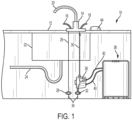
FIG. 1 is a schematic of the present remote control filter system shown mounted in a conventional residential sink application shown in a normal use position; -
FIG. 2 is a schematic of the system ofFIG. 1 shown in the filtering position; -
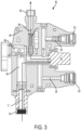
FIG. 3 is a vertical cross-section of the present system manifold shown in the normal flow position; -
FIG. 4 is a vertical cross-section of the present system manifold shown in the filtering position; -
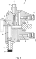
FIG. 5 is a vertical cross-section of the present system manifold shown in the bypass position; -
FIG. 6 is a plan view of the present remote control activator; -
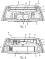
FIG. 7 is a cross-section taken along the line 7-7 ofFIG. 6 and in the direction generally indicated; -
FIG. 8 is a cross-section taken along the line 8-8 ofFIG. 6 and in the direction generally indicated; -
FIG. 9 is an exploded perspective view of the present remote control activator; and -
FIG. 10 is a top perspective view of the manifold. - Referring to
FIGs. 1 and2 , the present remote control water filter system (wich is a faucet filter system) is generally designated 10, and is shown mounted beneath aconventional countertop 12, bearing afaucet 14 having hot andcold water controls sink 22 with adrain 24 as is well known in the art. A hotwater supply conduit 26 is connected between thehot water control 16 and ashutoff valve 28, and a coldwater supply conduit 30 is connected between thehot water control 18 and a corresponding coldwater shutoff valve 32. Bothvalves water supply conduit 34 as is known in the art. - The present remote control
water filter system 10 includes acontrol manifold 36 connected between one of the hot and the coldwater shutoff valves water supply conduit system 10 is a filter apparatus generally designated 38, which is also preferably located beneath thecountertop 12. For the purposes of this application, thefilter apparatus 38, similar to the water filter system described above, is contemplated as any sort of conventional potable water treatment apparatus, including but not limited to granulated carbon filters, RO systems, UV treatment system, and the like. - The
filter apparatus 38 is in fluid communication with the manifold 36 by afluid inlet line 40 and afluid outlet line 42. As is known in the art, thelines remote controller 44 is shown disposed on the counter top 12 in close proximity to thefaucet 14. However, it will be understood that thecontroller 44 is not structurally connected to either thefaucet 14, the manifold 36, thefilter apparatus 38 or any of the corresponding lines or conduits. Instead, thecontroller 44 controls thesystem 10 wirelessly, preferably by RF signals as described in greater detail below. - An important feature of the
present system 10 is that the remote controller 44 (which is a wireless controller) controls components of the manifold 36 so that the manifold provides selective fluid communication between thewater supply line 34 and thefilter inlet 40. In other words, actuation of thecontroller 44 provides the user with the ability to determine whether unfiltered or filtered water is dispensed through the faucet spout 20 (through a common pathway in said faucet spout (20)). InFIG. 1 , a standard flow path is depicted in dashed lines, in which potable water flows through the manifold 36, through thefaucet inlet conduit 30 and to thefaucet 14. InFIG. 2 , thecontroller 44 is activated by the user and causes an internal valve in the manifold 36 to close, directing flow from the supply line through thefilter apparatus 38, then back to the manifold and ultimately to thefaucet 14, and out thespout 20. - Referring now to
FIGs. 3-5 , construction of thecontrol manifold 36 is shown in greater detail. A mainmanifold housing 46 defines afirst passageway 48 for providing fluid communication between thewater supply line 34 and thefaucet inlet conduit 30, thus bypassing thefilter apparatus 38. At least one remote actuated or controlledvalve 50, preferably an electronic solenoid valve or the like, is associated with the manifold 36 and is placed in fluid communication with thefirst passageway 48 in a first or open position as seen inFIG. 3 . As described in further detail below, eachvalve 50 is constructed and arranged for controlling, preferably by diverting, water flow in the manifold 36 to flow to thefilter apparatus 38 when filtered water is desired. - Thus, in a default operational condition, untreated potable water flows as depicted in line "F" from the
water supply line 34, through the shutoff valve 32 (which is a faucet shutoff valve and might be a water supply shutoff valve) and into thefirst passageway 48. Aflow switch 52 is disposed in thefirst passageway 48 downstream of thevalve 50 and is electronically connected to thecontroller 44 so that the valve can be activated to a second, closed position only when water is flowing through the first passageway and out the manifold 36 towards thefaucet 14. In the present application, "flow switch" will be understood to refer to any type of flow sensing device that sends an electrical signal upon sensing fluid flow, including but not limited to magnetic switches, turbines, pressure transducers and the like. While other switches are contemplated, as known in the art, thepresent flow switch 52 is a 1.89 Lpm (0.5 gpm) model having a magnet inside the manifold 36 and a reed switch external to the manifold for detecting when thefaucet 14 is open and water is flowing from thespout 20. - At each end of the
first passageway 48 themodule housing 46 is provided with a coupling for easy connection of thepresent system 10 into an existing water supply system. In the preferred embodiment, the couplings are threaded and compatible with existing conventional water supply plumbing connections, however other connections are contemplated, including push on, bayonet couplings, and other equivalent connection technologies. A first orwater supply coupling 54 is preferably the female threaded type for engagement upon a nipple of theshutoff valve 32. At the other end of thepassageway 48, a second coupling 56 (which is a faucet coupling), is preferably a male threaded type for connection to thefaucet inlet conduit 30, commonly a standard fitting found in most hardware and home repair stores. Another feature of thepresent system 10 is that thecouplings faucet 14. In addition, thecouplings coupling 54 is the sole structural support for thecontrol manifold 36 in thesystem 10. Referring now toFIG. 4 , upon thevalve 50 being activated by thecontroller 44, the valve is moved to a second or closed position in which water flows from thefirst coupling 54 into asecond passageway 58 in the manifold 36 for providing fluid communication between the water supply conduit and thefilter apparatus 38. More specifically, thesecond passageway 58 includes acoupling 60 configured for connection to an end of thefilter inlet line 40, and acoupling 62 configured for connection to an end of thefilter outlet line 42. Thesecond coupling 62 is then connected to athird passageway 64 which directs filtered water into thefirst passageway 48 past theflow switch 52 thefaucet inlet 30 and ultimately to thefaucet 14. In the preferred embodiment, acheck valve 66 is connected in thethird passageway 64 between thecoupling 62 and theflow switch 52 to prevent flow of untreated water back into thefilter apparatus 38. While thecheck valve 66 is shown as part of thecontrol manifold 36, it will be understood that it may be separately plumbed into the water flow path, or located elsewhere in thesystem 10, as long as the above-described function is achieved. Thus, depending on the position of thevalve 50 between the first and second positions, thesystem 10 is configured such that thefaucet 14 emits either filtered or unfiltered water through thefaucet spout 20 through the same flow path. Thus, thesame spout 20 emits either filtered or unfiltered water, depending on the position of thevalve 50. - Referring now to
FIG. 5 , in the event thesolenoid valve 50 malfunctions and remains in the closed or second position ofFIG. 4 , the user has the option of actuating a manual bypass to effect fluid flow through thefirst passageway 48. A supplementalmanual bypass valve 68 is connected to thefirst passageway 48, and when opened, creates a flow path past thevalve 50 and to thefaucet inlet 30. - Referring now to
FIGs. 6-9 , thecontroller 44 is described in greater detail. A frusto-conicalcontroller trim ring 70 is optional and snap fits to similarly shaped housing 72 (which is a biased controller housing) that defines an inner chamber 74 (which is an internal chamber). The housing is snap fit to aflexible base 76 that seals thechamber 74 from the entry of unwanted moisture. Acover disk 78 is relatively rigid, has at least one indicator opening 79 constructed and arranged to transmit light passing through alight divider 80 that receives light from a series of indicator LED's 81 located on a printedcircuit board 82. Thelight divider 80 controls the lateral projection of light so that individual LED's 81 are more easily read by the user. Also located on thecircuit board 82 is an RF transmitter component, well known in the art, and a push-button switch 84 (which defines a button and a on-off switch) that engages abattery housing 86. Thebattery housing 86 is constructed and arranged to house at least one and preferably two replaceable orrechargeable batteries 88 for powering thesystem 10. A plurality ofbosses 90 project vertically from thehousing 86 towards thecircuit board 82 and provide locating points for biasingelements 92, preferably coiled springs or the like. - As the user presses on the
controller housing 72, thedisk 78, thelight divider 80 and the printedcircuit board 82 move reciprocally as a unit against the force of the biasingelements 92, as well as relative to thebase 76 and cause theswitch 84 to close against thebattery housing 86. Once theswitch 84 is closed, an RF signal is sent to the manifold 36 to move thevalve 50 to the second position and permit water to flow through thefilter apparatus 38, and ultimately to thefaucet spout 20. While a particular, preferredremote controller 44 is described here, it will be understood that theremote controller 44 can be provided in other embodiments that function by user-initiated control over the generation of a signal for controlling thevalve 50. Such alternative controllers include, but are not limited to mobile phones or other mobile computers with wireless capability, whether or not hand-held, voice-activated devices, motion-activated devices, optical sensors, capacitive sensing devices, and similar technologies. - Referring now to
FIG. 10 , the manifold 36 is preferably enclosed in acase 94 provided with a second printedcircuit board 96 and astatus display board 98. The status parameters include, but are not limited to, filter life, error, signals, normal operational status, and the like. It is contemplated that thecircuit board 96 and thevalve 50 are powered by a designatedpower source 100, such as a battery pack, however the use of household current through a conventional wall socket is also contemplated. Thecircuit board 96 incorporates a valve controller shown schematically at 102. Thecircuit board 96, and more specifically thevalve controller 102 is activated by theflow switch 52 and is connected to thevalve 50 for enabling valve energization upon user actuation of thebutton 78 on thecontroller 44. Thesystem 10 is configured so that thevalve 50 is moved back to the first, default position ofFIG. 3 from the second position upon water flow being turned off at thefaucet 14. - While a particular embodiment of the present remote control faucet filter system has been shown and described, it will be appreciated by those skilled in the art that changes and modifications may be made thereto without departing from scope as set forth in the following claims.
Claims (9)
- Faucet filter system (10) for use with a faucet (14) connected to a water supply conduit (34), said system comprising:a unitary manifold (36) constructed and arranged for connection to the supply conduit and for providing selective fluid communication with the water supply conduit (34) and a filter inlet line (40);a filter apparatus (38) in fluid communication with said manifold (36) through said filter inlet line (40) and a filter outlet line (42) in fluid communication between a faucet inlet conduit (30);at least one remote actuated valve (50) associated with said manifold (36) and mounted to a main manifold housing (46) being constructed and arranged for selectively controlling water flow in said manifold (36) to said filter apparatus (38);a wireless controller (44) disposed remotely from said filter apparatus (38) and said manifold (36) and configured for actuating said at least one remote actuated valve (50) between a first position, in which water flows from the water supply conduit (34) through the faucet inlet conduit (30), and a second position, in which water flows from the water supply conduit (34), through said filter inlet line (40), to said filter apparatus (38), through said filter outlet line (42), and through said faucet inlet conduit (30);said system being configured such that depending on a valve actuation of said at least one remote actuated valve (50), between said first and second positions, either filtered or unfiltered water is sent to the faucet;said manifold (36) and associated said main manifold housing (46) define a first passageway (48) for providing fluid communication between the water supply conduit (34) and the faucet inlet conduit (30), and a second passageway (58) for providing fluid communication between the water supply conduit (34) and said filter apparatus (38), when said at least one remote actuated valve (50) is in said first position, water flows through said first passageway (48) directly to said faucet inlet conduit (30), and in said second position, water flows through said water supply conduit (34) through said second passageway (58) in said manifold (36) and to said filter apparatus (38);said manifold (36) includes a water supply coupling (54) configured for threaded connection to a water supply shutoff valve (32), and a faucet coupling (56) configured for threaded connection between said first passageway (48) and said faucet inlet conduit (30);said manifold (36) further includes a user actuated manual bypass valve (68) for selectively controlling flow between the water supply conduit (34) and said faucet inlet conduit (30); andsaid manifold (36) further includes a flow switch (52) in said first passageway (48) and electronically connected to said wireless controller (44) so that said at least one remote actuated valve (50) can be activated to said second position only when water is flowing through said first passageway (48) and out said manifold (36);the system being arranged to actuate said at least one remote actuated valve (50) to said first position from said second position upon water flow being turned off at the faucet (14).
- System according to claim 1, wherein said manifold (36) includes a third passageway (64) connecting said filter outlet line (42) with said faucet inlet conduit (30), and further including a check valve (66) in fluid communication with said filter outlet line (42) and configured for preventing flow of water back into said filter apparatus (38).
- System according to claim 1 or 2, wherein said wireless controller (44) is free of structural connection to said manifold (36), said faucet inlet conduit (30), said water supply conduit (34), said filter apparatus (38) or to said faucet (14).
- System according any of claims 1 to 3, wherein said water supply coupling (54) is the sole structural support for the manifold (36).
- System according any of claims 1 to 4, wherein said at least one remote actuated valve (50) is a remote controlled solenoid valve.
- System according any of claim 1 to 5, wherein said wireless controller (44) includes a biased controller housing (72) operating an on-off switch (84) arranged to be movable with said biased controller housing (72) so that depression of the biased controller housing (72) activates said on-off switch (84) for controlling said at least one remote actuated valve (50).
- System according claim 6, wherein said on-off switch (84) is connected to a printed circuit board (82) which is connected to said biased controller housing (72) for common movement.
- System according claim 6 or 7, wherein said wireless controller (44) includes a battery housing (86) located within an internal chamber (74) defined by said biased controller housing (72), and a button and said on-off switch (84) reciprocate relative to said battery housing (86).
- System according any of claims 1 to 8, wherein said manifold (36) further includes a flow switch (52) and is electronically connected to said wireless controller (44) so that said at least one remote actuated valve (50) can be activated to said second position only when water is flowing through said manifold (36); and
said manifold (36) further includes a printed circuit board (96) activated by said flow switch (52) and connected to said at least one remote actuated valve (50) for causing said valve actuation upon a user actuation of a button on said wireless controller (44).
Priority Applications (1)
| Application Number | Priority Date | Filing Date | Title |
|---|---|---|---|
| SM20250232T SMT202500232T1 (en) | 2015-01-22 | 2015-08-12 | Remote control faucet filter system |
Applications Claiming Priority (1)
| Application Number | Priority Date | Filing Date | Title |
|---|---|---|---|
| US14/602,854 US10675573B2 (en) | 2015-01-22 | 2015-01-22 | Remote control faucet filter system |
Publications (3)
| Publication Number | Publication Date |
|---|---|
| EP3048084A1 EP3048084A1 (en) | 2016-07-27 |
| EP3048084C0 EP3048084C0 (en) | 2025-03-26 |
| EP3048084B1 true EP3048084B1 (en) | 2025-03-26 |
Family
ID=54065669
Family Applications (1)
| Application Number | Title | Priority Date | Filing Date |
|---|---|---|---|
| EP15180775.7A Active EP3048084B1 (en) | 2015-01-22 | 2015-08-12 | Remote control faucet filter system |
Country Status (10)
| Country | Link |
|---|---|
| US (1) | US10675573B2 (en) |
| EP (1) | EP3048084B1 (en) |
| CN (1) | CN105817070A (en) |
| CA (1) | CA2902645C (en) |
| ES (1) | ES3033486T3 (en) |
| FR (1) | FR3031911B1 (en) |
| HK (1) | HK1224240A1 (en) |
| HU (1) | HUE071754T2 (en) |
| PL (1) | PL3048084T3 (en) |
| SM (1) | SMT202500232T1 (en) |
Families Citing this family (35)
| Publication number | Priority date | Publication date | Assignee | Title |
|---|---|---|---|---|
| US9032565B2 (en) | 2009-12-16 | 2015-05-19 | Kohler Co. | Touchless faucet assembly and method of operation |
| US9704329B2 (en) | 2014-05-01 | 2017-07-11 | Elkay Manufacturing Company | System and method for dispensing consumable liquids |
| WO2016110665A1 (en) * | 2015-01-07 | 2016-07-14 | Norgren Limited | Dual filter for moisture removal from a fluid flow |
| JP6970663B2 (en) * | 2015-10-08 | 2021-11-24 | エーエス アメリカ, インコーポレイテッドAS America, Inc. | Integrated faucet filtration system |
| US10227760B2 (en) * | 2016-03-08 | 2019-03-12 | Flowe Green, LLC | System and method for a smart faucet |
| DE102017209045A1 (en) * | 2017-05-30 | 2018-12-06 | Robert Bosch Gmbh | Filter housing and intermediate bottom |
| US11427484B1 (en) * | 2017-08-15 | 2022-08-30 | Aquacal Autopilot, Inc. | Salt water chlorine generator having an integral multifunctional flow sensor |
| US20190072319A1 (en) * | 2017-09-06 | 2019-03-07 | Bsh-Hausgeraete Gmbh | Assembly module for a household cooling appliance with a water filter and a valve, and household cooling appliance |
| WO2019055348A1 (en) * | 2017-09-12 | 2019-03-21 | A.O. Smith Corporation | Water faucet incorporating disinfecting features |
| CN107477238A (en) * | 2017-09-27 | 2017-12-15 | 甄旭蕾 | A kind of controlled in wireless tap and water outlet control method |
| USD863258S1 (en) * | 2017-12-07 | 2019-10-15 | As America, Inc. | Remote faucet controller |
| DE102018112362A1 (en) * | 2018-05-23 | 2019-11-28 | Grohe Ag | Apparatus and method for cleaning a drinking water treatment plant |
| CN108626440B (en) * | 2018-06-27 | 2024-12-31 | 日丰企业集团有限公司 | Filters and controls |
| CN109126261B (en) * | 2018-07-19 | 2021-03-12 | 广东好桦家家居科技有限公司 | Drinking water flow rate statistical system with water quality control function and control method thereof |
| RU2704574C1 (en) * | 2018-07-27 | 2019-10-29 | Денис Владимирович Воробьев | Crane device |
| US12264462B2 (en) | 2018-08-07 | 2025-04-01 | Delta Faucet Company | Liquid control apparatus and related methods |
| US11117816B2 (en) * | 2018-08-13 | 2021-09-14 | Geberit International Ag | Water disinfecting module, systems and methods |
| CA3055395C (en) | 2018-09-17 | 2025-09-23 | Delta Faucet Company | Metered dispense input device |
| US11519160B2 (en) | 2018-09-17 | 2022-12-06 | Delta Faucet Company | Metered dispense pot filler |
| DE102019203170A1 (en) * | 2019-03-08 | 2020-09-10 | Hansgrohe Se | Control device for a water-bearing sanitary fitting |
| CN115052831A (en) * | 2020-02-04 | 2022-09-13 | 三星电子株式会社 | Water purifier |
| US10894726B1 (en) | 2020-02-12 | 2021-01-19 | Aquisense Technologies, Llc | Water disinfecting module, systems and methods |
| US20220178122A1 (en) * | 2020-12-09 | 2022-06-09 | Kohler Co. | Sink system |
| CN214305432U (en) * | 2021-02-04 | 2021-09-28 | 北京科勒有限公司 | Induction faucet assembly |
| US12442166B2 (en) | 2021-05-14 | 2025-10-14 | Kohler Co. | Sink system and components |
| US11753293B2 (en) | 2021-12-22 | 2023-09-12 | Kraus Usa Plumbing Llc | Fluid dispensing systems and methods |
| IT202200001829A1 (en) * | 2022-02-02 | 2023-08-02 | Pea S R L | Drinking water filtration device |
| US12493355B2 (en) | 2022-04-14 | 2025-12-09 | Kohler Co. | Touchless plumbing control system |
| CA3258862A1 (en) * | 2022-06-20 | 2023-12-28 | Delta Faucet Company | ELECTRONIC FILTER SWITCH |
| KR20240010409A (en) | 2022-07-15 | 2024-01-23 | 에이에스엠 아이피 홀딩 비.브이. | Flow control arrangements with flow switches, semiconductor processing systems, and flow control methods |
| US12571191B2 (en) | 2022-10-06 | 2026-03-10 | Kohler Co. | System and methods for touchless faucet override |
| FR3147268A1 (en) * | 2023-03-28 | 2024-10-04 | Aralis | PORTABLE WATER TREATMENT DEVICE |
| GB2642367A (en) * | 2024-08-20 | 2026-01-07 | Chia Wei Chiang | Switching Device of Fluid Valve |
| US12529213B1 (en) * | 2024-09-25 | 2026-01-20 | Jui-Chien Chen | Water faucet with water flow monitoring |
| US12331500B1 (en) * | 2025-01-03 | 2025-06-17 | Danxuan Ding | Two-waterway structure for faucet |
Citations (2)
| Publication number | Priority date | Publication date | Assignee | Title |
|---|---|---|---|---|
| JP2002155555A (en) * | 2000-11-22 | 2002-05-31 | Meisui:Kk | Water feeding device |
| US20130112903A1 (en) * | 2010-07-05 | 2013-05-09 | Societe Econ'o | Device for identifying a command transmitted by a movable element of an item of furniture |
Family Cites Families (70)
| Publication number | Priority date | Publication date | Assignee | Title |
|---|---|---|---|---|
| US4210533A (en) | 1978-01-24 | 1980-07-01 | Jaromir Astl | Remote control valve for reverse osmosis water purifier |
| US4398562A (en) | 1981-07-06 | 1983-08-16 | Richdel, Inc. | Motorized diverter valve |
| US4556484A (en) | 1983-07-05 | 1985-12-03 | Teledyne Industries, Inc. | Water filters |
| US4744895A (en) | 1985-11-08 | 1988-05-17 | Aquasciences International, Inc. | Reverse osmosis water purifier |
| US4925551A (en) | 1986-03-21 | 1990-05-15 | Alfred J. Lipshultz | Portable water purification system including electronic memory panel assembly |
| EP0414691A4 (en) | 1988-03-22 | 1992-05-06 | Ryemetal Forgings (Vic) Pty. Ltd. | Electronic tapware |
| US4838310A (en) | 1988-03-28 | 1989-06-13 | Motorola, Inc. | Hydroelectrically powered, remotely controlled irrigation system |
| US5318070A (en) | 1991-08-19 | 1994-06-07 | Surabian Edward C | Electric faucet valve operator adapter |
| US5173178A (en) | 1991-09-24 | 1992-12-22 | Osaki Electric Co., Ltd. | Water purifying apparatus with timed discharge after non-use periods |
| JP3149495B2 (en) | 1992-01-10 | 2001-03-26 | 松下電器産業株式会社 | Hot water mixing equipment |
| JPH07171559A (en) | 1992-09-14 | 1995-07-11 | Mooen Japan Kk | Combined system of mixing water plug and water purifier |
| JP3340160B2 (en) | 1992-11-25 | 2002-11-05 | 松下電器産業株式会社 | Mixer tap with water purification function |
| GB2276656A (en) | 1993-04-02 | 1994-10-05 | Sage Passant Peter | Water supply isolation system |
| KR0152144B1 (en) | 1995-09-27 | 1998-10-15 | 김광호 | Concentrated Water Discharge Device of Water Purifier |
| US5829467A (en) | 1995-12-19 | 1998-11-03 | Spicher; Vincent M. | Residential hot water circulation system and associated method |
| US5813606A (en) | 1997-04-04 | 1998-09-29 | Ziff; Raymond | Radio controlled sprinkler control system |
| US5881755A (en) | 1997-11-05 | 1999-03-16 | Dieringer; Dale E. | Water supply control apparatus and method for use in homes or other structures |
| US6641727B1 (en) | 1998-03-04 | 2003-11-04 | American Standard International Inc. | Filter faucet |
| US6001244A (en) | 1998-07-10 | 1999-12-14 | Anthony Pipes | Performance water purification system |
| US6358395B1 (en) | 2000-08-11 | 2002-03-19 | H20 Technologies Ltd. | Under the counter water treatment system |
| US7874498B2 (en) * | 2000-10-25 | 2011-01-25 | Grundfos Pumps Corporation | Water control fixture having thermostatically controlled bypass valve |
| JP4187645B2 (en) | 2001-07-12 | 2008-11-26 | ダイナフロー株式会社 | Water purifier |
| US6797156B2 (en) | 2001-12-21 | 2004-09-28 | Yiu Chau Chau | Faucet water treatment |
| US6805330B2 (en) | 2002-01-03 | 2004-10-19 | I-Con Systems, Inc. | Flush-mount retrofit fluid control switch |
| AU2002306601A1 (en) | 2002-02-20 | 2003-09-09 | H2O Technologies, Ltd. | Under the counter water treatment system |
| US6797165B2 (en) | 2002-05-14 | 2004-09-28 | Dana Harrison | Modular multi-stage water filtration system |
| US6830479B2 (en) | 2002-11-20 | 2004-12-14 | Randall A. Holliday | Universal crimping connector |
| WO2004094990A2 (en) | 2003-04-22 | 2004-11-04 | University Of South Florida | Volumetric control apparatus for fluid dispensing |
| US20050236594A1 (en) | 2004-04-23 | 2005-10-27 | Lilly David J | Wireless remotely-operable utility flow-control valve and method |
| US6966986B1 (en) | 2004-07-12 | 2005-11-22 | Rwl Corporation | Under the counter filter installation |
| CA2474178C (en) | 2004-07-14 | 2010-10-12 | Hygiene-Technik Inc. | Sink side touchless foam dispenser |
| US7364651B2 (en) | 2004-07-15 | 2008-04-29 | Access Business Group International, Llc | Remotely controllable outlet for water treatment system |
| US7204930B2 (en) | 2004-07-16 | 2007-04-17 | Skagit Farmers Supply | Water purification system and method |
| US7353838B2 (en) | 2004-10-07 | 2008-04-08 | Watts Regulator Co. | Top mounted faucet assembly with air gap |
| JP2006281164A (en) | 2005-04-04 | 2006-10-19 | Toto Ltd | Water purifying device |
| US7743788B2 (en) | 2005-06-17 | 2010-06-29 | Watts Regulator Co. | Faucet assembly with water quality indicator |
| US7178543B2 (en) | 2005-06-27 | 2007-02-20 | Adams Charles L | Rapid hot water apparatus and method |
| US20090000024A1 (en) | 2005-11-16 | 2009-01-01 | Willow Design, Inc., A California Corporation | Dispensing system and method, and injector therefor |
| CA2573486A1 (en) | 2006-01-10 | 2007-07-10 | Moen Incorporated | Water filtration system |
| JP4613834B2 (en) | 2006-01-20 | 2011-01-19 | パナソニック電工株式会社 | Water treatment equipment |
| US8162236B2 (en) | 2006-04-20 | 2012-04-24 | Masco Corporation Of Indiana | Electronic user interface for electronic mixing of water for residential faucets |
| US7550084B2 (en) | 2006-05-02 | 2009-06-23 | Watts Water Technologies, Inc. | Reverse osmosis water filtering system |
| US7837866B2 (en) | 2006-10-12 | 2010-11-23 | Burrows Bruce D | Drainless reverse osmosis water purification system |
| US7900650B1 (en) | 2006-10-27 | 2011-03-08 | Wilson Thomas J | In-line water shut-off system and method of use thereof |
| US20080218362A1 (en) | 2007-03-06 | 2008-09-11 | Weiss Sanford B | Remote water shut-off device |
| CA2628301C (en) | 2007-04-09 | 2014-06-10 | Masco Corporation Of Indiana | Wireless power transfer device for a fluid delivery apparatus |
| GB0713140D0 (en) * | 2007-07-06 | 2007-08-15 | Illingworth Paul | Fluid flow control systems |
| US8180489B2 (en) | 2007-10-05 | 2012-05-15 | Culligan International Company | Communication system for a water softener system |
| GB0800650D0 (en) | 2008-01-15 | 2008-02-20 | Waterlogic Internat Uk Ltd | Water dispensers |
| US8201572B2 (en) | 2008-09-15 | 2012-06-19 | Segal Stanley H | Water supply control apparatus and method for use in homes or other structures |
| US9114365B2 (en) | 2008-10-09 | 2015-08-25 | Watts Water Technologies, Inc. | Shut off valve for a reverse osmosis water filtration system |
| US9009883B2 (en) | 2008-10-27 | 2015-04-21 | Whirlpool Corporation | Backsplash with pot filler |
| US8375970B2 (en) | 2008-11-10 | 2013-02-19 | Access Business Group International Llc | Valve system |
| WO2010054133A1 (en) * | 2008-11-10 | 2010-05-14 | Access Business Group International Llc | Faucet valve system |
| WO2011058515A1 (en) | 2009-11-11 | 2011-05-19 | Michael Librus | Remote-controlled, water dispensing system |
| US20110233286A1 (en) | 2010-03-29 | 2011-09-29 | John Pasquesi | Tepid water delivery system |
| US8308942B2 (en) | 2010-05-14 | 2012-11-13 | Paragon Water Systems, Inc. | Filter system with removable enhancement media |
| ITVR20100225A1 (en) | 2010-11-25 | 2012-05-26 | Scilm Spa | DEVICE FOR WATER PURIFICATION. |
| US8857466B1 (en) | 2011-02-03 | 2014-10-14 | Thomas J. Wilson | In-line utility shut-off system and method of use thereof |
| US20120318723A1 (en) | 2011-06-16 | 2012-12-20 | Whirlpool Corporation | Water dispensing system utilizing a smart filter |
| US10843108B2 (en) | 2011-06-21 | 2020-11-24 | Kinetico Incorporated | Water treatment system |
| CA2856196C (en) * | 2011-12-06 | 2020-09-01 | Masco Corporation Of Indiana | Ozone distribution in a faucet |
| US9546472B2 (en) | 2012-09-06 | 2017-01-17 | B/E Aerospace, Inc. | Aircraft galley plumbing system potable water manifold/filter block |
| US9217241B2 (en) | 2012-12-03 | 2015-12-22 | General Electric Company | Flow diverter device |
| US9528249B2 (en) | 2013-02-13 | 2016-12-27 | Component Hardware Group, Inc. | Valve assembly |
| CA2940240C (en) | 2014-03-07 | 2022-11-01 | Danco, Inc. | Smart water filter system |
| US20160052798A1 (en) | 2014-08-20 | 2016-02-25 | Aquion, Inc. | Enhanced water treatment system |
| CN204569576U (en) | 2015-04-01 | 2015-08-19 | 宁波日野电器有限公司 | A kind of can the purifier of intelligent management and control |
| CN205019825U (en) | 2015-07-16 | 2016-02-10 | 中山市晔汇电子有限公司 | A control processing device based on a remote wireless control filter valve |
| CN204999636U (en) | 2015-09-12 | 2016-01-27 | 葛咏红 | Be used for controllable formula water clean system of wireless long -distance of family |
-
2015
- 2015-01-22 US US14/602,854 patent/US10675573B2/en active Active
- 2015-05-08 CN CN201510232539.4A patent/CN105817070A/en active Pending
- 2015-08-12 EP EP15180775.7A patent/EP3048084B1/en active Active
- 2015-08-12 PL PL15180775.7T patent/PL3048084T3/en unknown
- 2015-08-12 ES ES15180775T patent/ES3033486T3/en active Active
- 2015-08-12 HU HUE15180775A patent/HUE071754T2/en unknown
- 2015-08-12 SM SM20250232T patent/SMT202500232T1/en unknown
- 2015-09-01 CA CA2902645A patent/CA2902645C/en active Active
- 2015-09-02 FR FR1558125A patent/FR3031911B1/en active Active
-
2016
- 2016-10-27 HK HK16112397.6A patent/HK1224240A1/en unknown
Patent Citations (2)
| Publication number | Priority date | Publication date | Assignee | Title |
|---|---|---|---|---|
| JP2002155555A (en) * | 2000-11-22 | 2002-05-31 | Meisui:Kk | Water feeding device |
| US20130112903A1 (en) * | 2010-07-05 | 2013-05-09 | Societe Econ'o | Device for identifying a command transmitted by a movable element of an item of furniture |
Non-Patent Citations (2)
| Title |
|---|
| GEL: "Manuale di uso e manutenzione AcquaClick", 7 January 2014 (2014-01-07), XP055363946, Retrieved from the Internet <URL:http://www.arbo.it/images/techsheets/acquaclik.pdf> [retrieved on 20170411] * |
| GEL: "Schieda Tecnica AcquaClick", 7 January 2014 (2014-01-07), pages 1 - 3, XP055363943, Retrieved from the Internet <URL:http://www.demshop.it/image/data/FILTRI/gel-Acquaclick-scheda.pdf> [retrieved on 20170411] * |
Also Published As
| Publication number | Publication date |
|---|---|
| CA2902645A1 (en) | 2016-07-22 |
| EP3048084C0 (en) | 2025-03-26 |
| PL3048084T3 (en) | 2025-07-28 |
| HK1224240A1 (en) | 2017-08-18 |
| ES3033486T3 (en) | 2025-08-04 |
| SMT202500232T1 (en) | 2025-07-22 |
| CA2902645C (en) | 2018-06-12 |
| FR3031911A1 (en) | 2016-07-29 |
| FR3031911B1 (en) | 2022-02-18 |
| CN105817070A (en) | 2016-08-03 |
| HUE071754T2 (en) | 2025-09-28 |
| EP3048084A1 (en) | 2016-07-27 |
| US20160214041A1 (en) | 2016-07-28 |
| US10675573B2 (en) | 2020-06-09 |
Similar Documents
| Publication | Publication Date | Title |
|---|---|---|
| US10675573B2 (en) | Remote control faucet filter system | |
| US11566405B2 (en) | Integrated bathroom electronic system | |
| US7997513B2 (en) | Oscillating faucet structure of a dual-outlet system | |
| US10640393B2 (en) | Faucet conversion system | |
| US8028355B2 (en) | Integrated bathroom electronic system | |
| US7014166B1 (en) | Faucet device operatable either manually or automatically | |
| CA2668155C (en) | Integrated bathroom electronic system | |
| WO2012125213A1 (en) | Automatic faucets | |
| EP3359751A1 (en) | Integrated faucet filtration system | |
| US20250382779A1 (en) | Electronic filter switch | |
| KR102140631B1 (en) | Electronic faucet of controller integrated type | |
| HK1227378A1 (en) | Remote control faucet filter system | |
| WO2020251605A1 (en) | Water control device | |
| CA2665030C (en) | Integrated bathroom electronic system | |
| CN115477378A (en) | Water purification equipment | |
| CN221500719U (en) | Drinking water equipment | |
| US12325000B2 (en) | Valve manifold for a water purification system | |
| KR102909343B1 (en) | Controling adapter for feed water and water purifier thereof | |
| US20250033997A1 (en) | Water filtration assembly and freeze prevention | |
| TWM669955U (en) | Waterway control device and controller thereof | |
| CN119083544A (en) | Interchangeable faucet design components | |
| HK40077804A (en) | Reverse osmosis drinking water system with dedicated powered faucet | |
| KR101216346B1 (en) | Sensor the whole type water electronic valve | |
| WO2020067864A1 (en) | Device for saving liquids at different temperatures |
Legal Events
| Date | Code | Title | Description |
|---|---|---|---|
| PUAI | Public reference made under article 153(3) epc to a published international application that has entered the european phase |
Free format text: ORIGINAL CODE: 0009012 |
|
| AK | Designated contracting states |
Kind code of ref document: A1 Designated state(s): AL AT BE BG CH CY CZ DE DK EE ES FI FR GB GR HR HU IE IS IT LI LT LU LV MC MK MT NL NO PL PT RO RS SE SI SK SM TR |
|
| AX | Request for extension of the european patent |
Extension state: BA ME |
|
| STAA | Information on the status of an ep patent application or granted ep patent |
Free format text: STATUS: REQUEST FOR EXAMINATION WAS MADE |
|
| 17P | Request for examination filed |
Effective date: 20170118 |
|
| RBV | Designated contracting states (corrected) |
Designated state(s): AL AT BE BG CH CY CZ DE DK EE ES FI FR GB GR HR HU IE IS IT LI LT LU LV MC MK MT NL NO PL PT RO RS SE SI SK SM TR |
|
| STAA | Information on the status of an ep patent application or granted ep patent |
Free format text: STATUS: EXAMINATION IS IN PROGRESS |
|
| 17Q | First examination report despatched |
Effective date: 20170428 |
|
| REG | Reference to a national code |
Ref country code: HK Ref legal event code: DE Ref document number: 1227378 Country of ref document: HK |
|
| REG | Reference to a national code |
Ref country code: HK Ref legal event code: WD Ref document number: 1227378 Country of ref document: HK |
|
| GRAP | Despatch of communication of intention to grant a patent |
Free format text: ORIGINAL CODE: EPIDOSNIGR1 |
|
| STAA | Information on the status of an ep patent application or granted ep patent |
Free format text: STATUS: GRANT OF PATENT IS INTENDED |
|
| RIC1 | Information provided on ipc code assigned before grant |
Ipc: E03C 1/05 20060101ALN20241010BHEP Ipc: C02F 1/00 20060101AFI20241010BHEP |
|
| RIC1 | Information provided on ipc code assigned before grant |
Ipc: E03C 1/05 20060101ALN20241014BHEP Ipc: C02F 1/00 20060101AFI20241014BHEP |
|
| RIC1 | Information provided on ipc code assigned before grant |
Ipc: E03C 1/05 20060101ALN20241029BHEP Ipc: C02F 1/00 20060101AFI20241029BHEP |
|
| INTG | Intention to grant announced |
Effective date: 20241113 |
|
| GRAS | Grant fee paid |
Free format text: ORIGINAL CODE: EPIDOSNIGR3 |
|
| GRAA | (expected) grant |
Free format text: ORIGINAL CODE: 0009210 |
|
| STAA | Information on the status of an ep patent application or granted ep patent |
Free format text: STATUS: THE PATENT HAS BEEN GRANTED |
|
| AK | Designated contracting states |
Kind code of ref document: B1 Designated state(s): AL AT BE BG CH CY CZ DE DK EE ES FI FR GB GR HR HU IE IS IT LI LT LU LV MC MK MT NL NO PL PT RO RS SE SI SK SM TR |
|
| REG | Reference to a national code |
Ref country code: GB Ref legal event code: FG4D |
|
| REG | Reference to a national code |
Ref country code: CH Ref legal event code: EP |
|
| REG | Reference to a national code |
Ref country code: DE Ref legal event code: R096 Ref document number: 602015091280 Country of ref document: DE |
|
| REG | Reference to a national code |
Ref country code: IE Ref legal event code: FG4D |
|
| U01 | Request for unitary effect filed |
Effective date: 20250424 |
|
| U07 | Unitary effect registered |
Designated state(s): AT BE BG DE DK EE FI FR IT LT LU LV MT NL PT RO SE SI Effective date: 20250430 |
|
| PG25 | Lapsed in a contracting state [announced via postgrant information from national office to epo] |
Ref country code: RS Free format text: LAPSE BECAUSE OF FAILURE TO SUBMIT A TRANSLATION OF THE DESCRIPTION OR TO PAY THE FEE WITHIN THE PRESCRIBED TIME-LIMIT Effective date: 20250626 |
|
| PG25 | Lapsed in a contracting state [announced via postgrant information from national office to epo] |
Ref country code: NO Free format text: LAPSE BECAUSE OF FAILURE TO SUBMIT A TRANSLATION OF THE DESCRIPTION OR TO PAY THE FEE WITHIN THE PRESCRIBED TIME-LIMIT Effective date: 20250626 |
|
| PG25 | Lapsed in a contracting state [announced via postgrant information from national office to epo] |
Ref country code: HR Free format text: LAPSE BECAUSE OF FAILURE TO SUBMIT A TRANSLATION OF THE DESCRIPTION OR TO PAY THE FEE WITHIN THE PRESCRIBED TIME-LIMIT Effective date: 20250326 |
|
| REG | Reference to a national code |
Ref country code: ES Ref legal event code: FG2A Ref document number: 3033486 Country of ref document: ES Kind code of ref document: T3 Effective date: 20250804 |
|
| REG | Reference to a national code |
Ref country code: GR Ref legal event code: EP Ref document number: 20250401296 Country of ref document: GR Effective date: 20250707 |
|
| PGFP | Annual fee paid to national office [announced via postgrant information from national office to epo] |
Ref country code: HU Payment date: 20250730 Year of fee payment: 11 |
|
| REG | Reference to a national code |
Ref country code: HU Ref legal event code: AG4A Ref document number: E071754 Country of ref document: HU |
|
| U20 | Renewal fee for the european patent with unitary effect paid |
Year of fee payment: 11 Effective date: 20250827 |
|
| PGFP | Annual fee paid to national office [announced via postgrant information from national office to epo] |
Ref country code: SM Payment date: 20250723 Year of fee payment: 11 |
|
| PGFP | Annual fee paid to national office [announced via postgrant information from national office to epo] |
Ref country code: ES Payment date: 20250901 Year of fee payment: 11 |
|
| PGFP | Annual fee paid to national office [announced via postgrant information from national office to epo] |
Ref country code: GR Payment date: 20250826 Year of fee payment: 11 |
|
| PGFP | Annual fee paid to national office [announced via postgrant information from national office to epo] |
Ref country code: TR Payment date: 20250721 Year of fee payment: 11 Ref country code: PL Payment date: 20250801 Year of fee payment: 11 |
|
| PGFP | Annual fee paid to national office [announced via postgrant information from national office to epo] |
Ref country code: GB Payment date: 20250827 Year of fee payment: 11 |
|
| PGFP | Annual fee paid to national office [announced via postgrant information from national office to epo] |
Ref country code: CH Payment date: 20250901 Year of fee payment: 11 |
|
| PGFP | Annual fee paid to national office [announced via postgrant information from national office to epo] |
Ref country code: IE Payment date: 20250827 Year of fee payment: 11 Ref country code: CZ Payment date: 20250724 Year of fee payment: 11 |
|
| PG25 | Lapsed in a contracting state [announced via postgrant information from national office to epo] |
Ref country code: SK Free format text: LAPSE BECAUSE OF FAILURE TO SUBMIT A TRANSLATION OF THE DESCRIPTION OR TO PAY THE FEE WITHIN THE PRESCRIBED TIME-LIMIT Effective date: 20250326 |
|
| PG25 | Lapsed in a contracting state [announced via postgrant information from national office to epo] |
Ref country code: IS Free format text: LAPSE BECAUSE OF FAILURE TO SUBMIT A TRANSLATION OF THE DESCRIPTION OR TO PAY THE FEE WITHIN THE PRESCRIBED TIME-LIMIT Effective date: 20250726 |
|
| PGFP | Annual fee paid to national office [announced via postgrant information from national office to epo] |
Ref country code: CY Payment date: 20250724 Year of fee payment: 11 |
|
| PLBE | No opposition filed within time limit |
Free format text: ORIGINAL CODE: 0009261 |
|
| STAA | Information on the status of an ep patent application or granted ep patent |
Free format text: STATUS: NO OPPOSITION FILED WITHIN TIME LIMIT |
|
| REG | Reference to a national code |
Ref country code: CH Ref legal event code: L10 Free format text: ST27 STATUS EVENT CODE: U-0-0-L10-L00 (AS PROVIDED BY THE NATIONAL OFFICE) Effective date: 20260211 |
|
| 26N | No opposition filed |
Effective date: 20260105 |
|
| PG25 | Lapsed in a contracting state [announced via postgrant information from national office to epo] |
Ref country code: MC Free format text: LAPSE BECAUSE OF FAILURE TO SUBMIT A TRANSLATION OF THE DESCRIPTION OR TO PAY THE FEE WITHIN THE PRESCRIBED TIME-LIMIT Effective date: 20250326 |