EP3047977A2 - Liquid ejecting apparatus and method of detection - Google Patents
Liquid ejecting apparatus and method of detection Download PDFInfo
- Publication number
- EP3047977A2 EP3047977A2 EP16152799.9A EP16152799A EP3047977A2 EP 3047977 A2 EP3047977 A2 EP 3047977A2 EP 16152799 A EP16152799 A EP 16152799A EP 3047977 A2 EP3047977 A2 EP 3047977A2
- Authority
- EP
- European Patent Office
- Prior art keywords
- section
- amount
- space
- threshold value
- medium
- Prior art date
- Legal status (The legal status is an assumption and is not a legal conclusion. Google has not performed a legal analysis and makes no representation as to the accuracy of the status listed.)
- Granted
Links
Images




Classifications
-
- B—PERFORMING OPERATIONS; TRANSPORTING
- B41—PRINTING; LINING MACHINES; TYPEWRITERS; STAMPS
- B41J—TYPEWRITERS; SELECTIVE PRINTING MECHANISMS, i.e. MECHANISMS PRINTING OTHERWISE THAN FROM A FORME; CORRECTION OF TYPOGRAPHICAL ERRORS
- B41J25/00—Actions or mechanisms not otherwise provided for
- B41J25/304—Bodily-movable mechanisms for print heads or carriages movable towards or from paper surface
- B41J25/308—Bodily-movable mechanisms for print heads or carriages movable towards or from paper surface with print gap adjustment mechanisms
-
- B—PERFORMING OPERATIONS; TRANSPORTING
- B41—PRINTING; LINING MACHINES; TYPEWRITERS; STAMPS
- B41J—TYPEWRITERS; SELECTIVE PRINTING MECHANISMS, i.e. MECHANISMS PRINTING OTHERWISE THAN FROM A FORME; CORRECTION OF TYPOGRAPHICAL ERRORS
- B41J11/00—Devices or arrangements of selective printing mechanisms, e.g. ink-jet printers or thermal printers, for supporting or handling copy material in sheet or web form
- B41J11/20—Platen adjustments for varying the strength of impression, for a varying number of papers, for wear or for alignment, or for print gap adjustment
-
- B—PERFORMING OPERATIONS; TRANSPORTING
- B41—PRINTING; LINING MACHINES; TYPEWRITERS; STAMPS
- B41J—TYPEWRITERS; SELECTIVE PRINTING MECHANISMS, i.e. MECHANISMS PRINTING OTHERWISE THAN FROM A FORME; CORRECTION OF TYPOGRAPHICAL ERRORS
- B41J2/00—Typewriters or selective printing mechanisms characterised by the printing or marking process for which they are designed
- B41J2/005—Typewriters or selective printing mechanisms characterised by the printing or marking process for which they are designed characterised by bringing liquid or particles selectively into contact with a printing material
- B41J2/01—Ink jet
- B41J2/17—Ink jet characterised by ink handling
- B41J2/175—Ink supply systems ; Circuit parts therefor
-
- B—PERFORMING OPERATIONS; TRANSPORTING
- B41—PRINTING; LINING MACHINES; TYPEWRITERS; STAMPS
- B41J—TYPEWRITERS; SELECTIVE PRINTING MECHANISMS, i.e. MECHANISMS PRINTING OTHERWISE THAN FROM A FORME; CORRECTION OF TYPOGRAPHICAL ERRORS
- B41J29/00—Details of, or accessories for, typewriters or selective printing mechanisms not otherwise provided for
- B41J29/02—Framework
-
- B—PERFORMING OPERATIONS; TRANSPORTING
- B41—PRINTING; LINING MACHINES; TYPEWRITERS; STAMPS
- B41J—TYPEWRITERS; SELECTIVE PRINTING MECHANISMS, i.e. MECHANISMS PRINTING OTHERWISE THAN FROM A FORME; CORRECTION OF TYPOGRAPHICAL ERRORS
- B41J29/00—Details of, or accessories for, typewriters or selective printing mechanisms not otherwise provided for
- B41J29/02—Framework
- B41J29/023—Framework with reduced dimensions
-
- B—PERFORMING OPERATIONS; TRANSPORTING
- B41—PRINTING; LINING MACHINES; TYPEWRITERS; STAMPS
- B41J—TYPEWRITERS; SELECTIVE PRINTING MECHANISMS, i.e. MECHANISMS PRINTING OTHERWISE THAN FROM A FORME; CORRECTION OF TYPOGRAPHICAL ERRORS
- B41J29/00—Details of, or accessories for, typewriters or selective printing mechanisms not otherwise provided for
- B41J29/12—Guards, shields or dust excluders
- B41J29/13—Cases or covers
-
- B—PERFORMING OPERATIONS; TRANSPORTING
- B41—PRINTING; LINING MACHINES; TYPEWRITERS; STAMPS
- B41J—TYPEWRITERS; SELECTIVE PRINTING MECHANISMS, i.e. MECHANISMS PRINTING OTHERWISE THAN FROM A FORME; CORRECTION OF TYPOGRAPHICAL ERRORS
- B41J29/00—Details of, or accessories for, typewriters or selective printing mechanisms not otherwise provided for
- B41J29/38—Drives, motors, controls or automatic cut-off devices for the entire printing mechanism
Definitions
- the present invention relates to a liquid ejecting apparatus and a method of detection.
- a liquid ejecting apparatus configured to eject liquid onto a medium to form an image on the medium has been used.
- a liquid ejecting apparatus too small an amount of space between a medium and an ejecting section may bring the medium and the ejecting section into contact with each other, thereby causing a malfunction.
- a technology for preventing an amount of space between a medium and an ejecting section from becoming too small has been disclosed.
- JP-A-2014-124819 discloses an image recording apparatus (liquid ejecting apparatus) including a detecting section configured to detect when an amount of space between a medium and an ejecting section has become smaller than a predetermined amount of space.
- An advantage of some aspects of the invention is that liquid is prevented from being ejected from an ejecting section onto a medium in a state where an amount of space between the medium and the ejecting section is too large.
- a liquid ejecting apparatus includes: a supporting section capable of supporting a medium; an ejecting section capable of ejecting liquid onto the medium supported by the supporting section; and a first detecting section capable of detecting whether an amount of space between the medium supported by the supporting section and the ejecting section is equal to or more than a first threshold value.
- the first detecting section may be capable of detecting, according to an input quantity of electromagnetic waves, whether the amount of space is equal to or more than the first threshold value.
- the liquid ejecting apparatus may further include an output section capable of, in a case where the amount of space has been detected by the first detecting section as being equal to or more than the first threshold value, outputting information indicating that the amount of space is equal to or more than the first threshold value.
- the liquid ejecting apparatus may further include an amount-of-space adjusting section configured to reduce the amount of space in a case where the amount of space has been detected by the first detecting section as being equal to or more than the first threshold value.
- the liquid ejecting apparatus may further include a second detecting section capable of detecting whether the amount of space is equal to or less than a second threshold value that is smaller than the first threshold value.
- the second detecting section may be capable of detecting, according to an input quantity of electromagnetic waves, whether the amount of space is equal to or less than the second threshold value.
- the liquid ejecting apparatus may further include an output section capable of, in a case where the amount of space has been detected by the second detecting section as being equal to or less than the second threshold value, outputting information indicating that the amount of space is equal to or less than the second threshold value.
- the liquid ejecting apparatus may further include an amount-of-space adjusting section configured to increase the amount of space in a case where the amount of space has been detected by the second detecting section as being equal to or less than the second threshold value.
- the liquid ejecting apparatus may further include a control section configured to, in a case where the amount of space has been detected by the first detecting section and the second detecting section as being more than the second threshold value and less than the first threshold value, control the ejecting section so that the ejecting section forms an image by ejecting the liquid onto the medium supported by the supporting section.
- a method of detection according to a second aspect of the invention includes detecting whether an amount of space between a medium supported by a supporting section capable of supporting the medium and an ejecting section capable of ejecting liquid onto the medium supported by the supporting section is equal to or more than a first threshold value.
- Embodiment 1 ( Figs. 1 to 4C )
- Fig. 1 is a schematic perspective view of a recording apparatus 1 according to Embodiment 1 of the invention
- Fig. 2 is a schematic front view of the recording apparatus 1 according to Embodiment 1 of the invention.
- the recording apparatus 1 includes a medium supporting unit 2 configured to move a medium P (see Figs. 4A to 4C ) in either direction of movement A while supporting the medium P.
- the medium supporting unit 2 includes a tray 4, which serves as a supporting section configured to support a medium.
- the recording apparatus 1 includes a medium transporting section 3 configured to transport the medium P supported by the tray 4 in either direction of movement A (i.e., to move the medium P and a recording head 7 described later, which serves as an ejecting section, relative to each other). Further, the tray 4 is mounted on a stage 5. Rotating a rotating lever 20 causes the tray 4, together with the stage 5, to move in either height direction C.
- the rotating lever 20 can be manually rotated by a user and can also be automatically rotated by a control section 8 (see Fig. 3 ) controlling a tray moving motor 16.
- the recording apparatus 1 includes a body, and the body includes the recording head 7, which is capable of ejecting ink (which is an example of liquid).
- the recording head 7 corresponds to an ejecting section capable of ejecting liquid onto the medium P.
- the recording apparatus 1 according to Embodiment 1 forms a desired image by causing a carriage 6 provided with the recording head 7 to reciprocate in cross directions B that cross the directions of movement A and thereby causing the recording head 7, which serves as an ejecting section configured to eject ink, to reciprocate and, at the same time, eject the ink onto the medium P supported by the tray 4.
- the ejecting section is capable of ejecting liquid while moving in the cross directions B that cross the directions of movement A.
- the recording apparatus 1 performs recording while moving the tray 4 toward a near side of Fig. 1 (i.e., in a downward and leftward direction in Fig. 1 ) after moving the tray 4, onto which the medium P has been set, from a set position to a recording start position.
- the set position which is a position where the medium P is set onto the tray 4, is located on the near side of Fig. 1 .
- the recording start position is located on a far side of Fig. 1 (which faces in an upward and rightward direction in Fig. 1 ).
- the recording apparatus 1 includes the tray 4, which serves as a supporting section capable of supporting a medium P, and the recording head 7, which serves as an ejecting section capable of ejecting ink (which is an example of liquid) onto the medium P supported by the tray 4.
- the recording apparatus 1 includes a first sensor S1, which serves as a first detecting section.
- the first sensor S1 is configured to be able to detect whether an amount of space or distance PG (see Fig. 4A ) between the medium P supported by the tray 4 and the recording head 7 is equal to or more than a first threshold value (or whether the amount of space PG is more than the first threshold value).
- This configuration allows the recording apparatus 1 according to Embodiment 1 to detect a state where the amount of space PG is too large. This makes it possible to prevent the ink from being ejected from the recording head 7 onto the medium P in a state where the amount of space PG is too large.
- the recording apparatus 1 according to Embodiment 1 is capable of detecting whether the amount of space PG is more than the first threshold value, as well as whether the amount of space PG is equal to or more than the first threshold value.
- the following description takes, as an example, a case where the recording apparatus 1 according to Embodiment 1 detects whether the amount of space PG is equal to or more than the first threshold value. Therefore, the clause "whether the amount of space PG is equal to or more than the first threshold value" can be replaced by the clause "whether the amount of space PG is more than the first threshold value".
- the recording apparatus 1 includes a second sensor S2, which serves as a second detecting section capable of detecting whether the amount of space PG is equal to or less than a second threshold value that is smaller than the first threshold value (or whether the amount of space PG is less than the second threshold value).
- a second sensor S2 which serves as a second detecting section capable of detecting whether the amount of space PG is equal to or less than a second threshold value that is smaller than the first threshold value (or whether the amount of space PG is less than the second threshold value).
- This configuration makes it possible not only to detect a state where the amount of space PG is too large but also to detect a state where the amount of space PG is too small.
- the recording apparatus 1 according to Embodiment 1 is capable of detecting whether the amount of space PG is less than the second threshold value, as well as whether the amount of space PG is equal to or less than the second threshold value.
- the following description takes, as an example, a case where the recording apparatus 1 according to Embodiment 1 detects whether the amount of space PG is equal to or less than the second threshold value. Therefore, the clause "whether the amount of space PG is equal to or less than the second threshold value" can be replaced by the clause "whether the amount of space PG is less than the second threshold value".
- the first sensor S1 and the second sensor S2 each include a light-emitting section Se and a light-receiving section Sr.
- the first sensor S1 is configured to irradiate its light-receiving section Sr with light from its light-emitting section Se and detect, according to whether its light-receiving section Sr has received the light, a state where the amount of space PG is too large
- the second sensor S2 is configured to irradiate its light-receiving section Sr with light from its light-emitting section Se and detect, according to whether its light-receiving section Sr has received the light, a state where the amount of space PG is too small.
- the first sensor S1 is capable of detecting, according to an input quantity of electromagnetic waves, whether the amount of space PG is equal to or more than the first threshold value
- the second sensor S2 is capable of detecting, according to an input quantity of electromagnetic waves, whether the amount of space PG is equal to or less than the second threshold value.
- electromagnetic waves allow the first sensor S1 to detect a state where the amount of space PG is too large without making contact with the medium P, and allow the second sensor S2 to detect a state where the amount of space PG is too small without making contact with the medium P. Consequently, the recording apparatus 1 according to Embodiment 1 is configured to be able to detect the amount of space PG without causing damage to the medium P by making contact with it.
- the first sensor S1 and the second sensor S2 according to Embodiment 1 are both configured to emit light along a recording surface of the medium P (i.e., a supporting surface of the medium P) and detect the amount of space PG according to whether the light is received.
- the first sensor S1 and the second sensor S2 according to Embodiment 1 may both be configured to emit light toward the recording surface of the medium P (i.e., in a direction that crosses the recording surface of the medium P) and detect the amount of space PG according to the reception intensity of reflection of the light.
- the first sensor S1 and the second sensor S2 be both configured to emit light along the recording surface of the medium P and detect the amount of space PG according to whether the light is received.
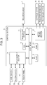
- Fig. 3 is a block diagram of the recording apparatus 1 according to Embodiment 1.
- the control section 8 includes a CPU 9 configured to take overall control of the recording apparatus 1.
- the CPU 9 is connected via a system bus 10 to a ROM 11 and a RAM 12.
- Various programs, maintenance sequences, and the like that the CPU 9 executes are stored in the ROM 11.
- data can be temporarily stored.
- the CPU 9 is connected via the system bus 10 to a head driving section 13 configured to drive the recording head 7.
- the CPU 9 is connected via the system bus 10 to a motor driving section 17.
- the motor driving section 17 is connected to a carriage motor 14 configured to move the carriage 6 provided with the recording head 7, a transporting motor 15 provided in the medium transporting section 3 so as to transport the medium P, and the tray moving motor 16, which is configured to rotate the rotating lever 20 to make it possible to adjust the amount of space PG by moving the tray 4 in either height direction C.
- the CPU 9 is connected via the system bus 10 to an input/output section 18.
- the input/output section 18 is connected to the first sensor S1, the second sensor S2, a touch panel 19, and a PC 30 configured to transmit and receive data, such as recording data, and signals.
- This configuration enables the control section 8 to execute an image forming operation by controlling the recording head 7 and the medium transporting section 3 so that the recording head 7 performs an ejecting operation and the medium transporting section 3 performs an operation of moving the medium P and the recording head 7 relative to each other.
- control section 8 can serve as an amount-of-space adjusting section to reduce the amount of space PG by rotating the rotating lever 20 in a case where the amount of space PG has been detected by the first sensor S1 as being equal to or more than the first threshold value. This allows the recording apparatus 1 according to Embodiment 1 to automatically adjust the amount of space PG in a case where the amount of space PG is too large and thereby prevent the ink from being ejected from the recording head 7 to the medium P in the state where the amount of space PG is too large.
- control section 8 can increase the amount of space PG by rotating the rotating lever 20 in a case where the amount of space PG has been detected by the second sensor S2 as being equal to or less than the second threshold value. This allows the recording apparatus 1 according to Embodiment 1 to automatically adjust the amount of space PG in a case where the amount of space PG is too small and thereby prevent the ink from being ejected from the recording head 7 to the medium P in the state where the amount of space PG is too small.
- control section 8 can serve as an output section that, in a case where the amount of space PG has been detected by the first sensor S1 as being equal to or more than the first threshold value, outputs information indicating that the amount of space PG is equal to or more than the first threshold value to at least either the touch panel 19 or a monitor of the PC 30 via the input/output section 18 and causes the touch panel 19 and/or the monitor to display the information. This makes it possible to notify the user of a state where the amount of space PG is too large.
- the control section 8 can output information indicating that the amount of space PG is equal to or less than the second threshold value to at least either the touch panel 19 or the monitor of the PC 30 via the input/output section 18 and cause the touch panel 19 and/or the monitor to display the information. This makes it possible to notify the user of a state where the amount of space PG is too small.
- a state where the amount of space PG falls outside an appropriate range a state where the amount of space PG is too small (i.e., a case where the amount of space PG has been detected by the second sensor S2 as being equal to or less than the second threshold value), and a state where the amount of space PG is too large (i.e., a case where the amount of space PG has been detected by the first sensor S1 as being equal to or more than the first threshold value) are described.
- Fig. 4A shows a state where the amount of space PG falls within an appropriate range.
- Fig. 4B shows a state where the amount of space PG is too small.
- Fig. 4C shows a state where the amount of space PG is too large.
- the control section 8 determines that the amount of space PG falls within an appropriate range. In other words, the control section 8 determines, on the basis of the fact that the light L1 emitted from the light-emitting section Se of the first sensor S1 is not received by the light-receiving section Sr of the first sensor S1, that the amount of space PG has not become equal to or more than the first threshold value.
- control section 8 determines, on the basis of the fact that the light L2 emitted from the light-emitting section Se of the second sensor S2 is received by the light-receiving section Sr of the second sensor S2, that the amount of space PG has not become equal to or less than the second threshold value.
- the control section 8 determines that the amount of space PG falls within an appropriate range (i.e., a range of more than the second threshold value to less than the first threshold value).
- the control section 8 determines that the amount of space PG is too small. In other words, the control section 8 determines, on the basis of the fact that the light L2 emitted from the light-emitting section Se of the second sensor S2 is not received by the light-receiving section Sr of the second sensor S2, that the amount of space PG has become equal to or less than the second threshold value.
- the control section 8 determines that the amount of space PG is too small (i.e., equal to or less than the second threshold value).
- the control section 8 determines that the amount of space PG is too large. In other words, the control section 8 determines, on the basis of the fact that the light L1 emitted from the light-emitting section Se of the first sensor S1 is not received by the light-receiving section Sr of the first sensor S1, that the amount of space PG has become equal to or more than the first threshold value.
- the control section 8 determines that the amount of space PG is too large (i.e., equal to or more than the first threshold value).
- the control section 8 controls the recording head 7 so that the recording head 7 forms an image by ejecting the ink onto the medium P supported by the tray 4.
- the recording apparatus 1 is configured to be able to prevent the medium P and the recording head 7 from making contact with each other, prevent deterioration in recording quality, and prevent an amount of mist that is generated by ejecting the ink from increasing and thus staining an inner part of the apparatus or the medium P.
- control section 8 may cause the first sensor S1 to detect whether the amount of space PG is more than the first threshold value and cause the second sensor S2 to detect whether the amount of space PG is less than the second threshold value and, in a case where the amount of space PG has been detected as being equal to or more than the second threshold value and equal to or less than the first threshold vale, may control the recording head 7 so that the recording head 7 forms an image by ejecting the ink onto the medium P supported by the tray 4.
- the recording apparatus 1 is configured to be capable of adjusting the amount of space PG by changing position of the supporting section (tray 4) supporting the medium P in either height direction C.
- the recording apparatus 1 may be configured to be capable of adjusting the amount of space PG by changing the position of the recording head 7 in either height direction C.
- the invention is also applicable to a recording apparatus (liquid ejecting apparatus) configured totally differently from the recording apparatus 1 according to Embodiment 1.
- Fig. 5 is a schematic side view of a recording apparatus 21 according to Embodiment 2.
- the recording apparatus 21 includes a setting section 22 onto which a roll medium P is set, a supporting section 24 configured to support the medium P, and a rewinding section 25 configured to rewind the medium P into a roll. Moreover, the recording apparatus 21 is capable of transporting the medium P in a transport direction A from the setting section 22 to the rewinding section 25 via the supporting section 24. That is, the recording apparatus 21 transports the medium P along a transport path extending from the setting section 22 to the rewinding section 25.
- the setting section 22 rotates in a direction of rotation D to feed out the medium P
- the rewinding section 25 rotates in the direction of rotation D to rewind the medium P.
- the recording apparatus 21 according to Embodiment 1 has transporting rollers 23 provided in the transport path of the medium P.
- the transporting rollers are constituted by a pair of rollers whose axes of rotation extend in a cross direction B that crosses the transport direction A. This allows the recording apparatus 21 according to Embodiment 1 to be configured such that, in the transport path of the medium P, the transporting rollers 23 transport the medium P fed out from the setting section 22 and the rewinding section 25 rewinds the medium P transported to the rewinding section 25 by the transporting rollers 23.
- the recording apparatus 21 includes a recording head 27, which serves as an ejecting section configured to eject ink.
- the recording apparatus 21 forms a desired image by causing the recording head 27 to eject ink while causing the recording head 27 via a carriage 26 to reciprocate along the cross direction B. This configuration allows the recording head 27 to form the image by ejecting the ink onto the medium P.
- a first sensor S1 and a second sensor S2 are provided on an upstream side of the carriage 26 in the transport path of the medium P.
- a first sensor S1 and a second sensor S2 are configured in the same way as the first sensor S1 and the second sensor S2 of the recording apparatus 1 according to Embodiment 1.
- a movable platen 28 that can be controlled by a control section (not illustrated) to move in either height direction C.
- This configuration enables the recording apparatus 21 according to Embodiment 2 to, in the same way as the recording apparatus 1 according to Embodiment 1, automatically adjust an amount of space PG on the basis of results of detection performed by the first sensor S1 and the second sensor S2.
- Fig. 6 is a schematic perspective view of a recording apparatus 31 according to Embodiment 3.
- the recording apparatus 31 is a recording apparatus of a so-called flat-bed type.
- the recording apparatus 31 includes a body section 32 and a medium supporting section (supporting section) 34 capable of supporting a medium P.
- the body section 32 includes a recording head 37, which serves as an ejecting section configured to eject ink.
- the recording apparatus 31 is capable of moving the recording head 37 in either direction of movement A with respect to the medium supporting section 34. That is, the body section 32 serves also as an ejecting unit capable of moving the medium P and the recording head 37 relative to each other in either direction of movement A.
- the recording head 37 can be moved by a carriage 36 in either cross direction B that crosses the directions of movement A.
- the recording apparatus 31 according to Embodiment 3 forms a desired image by causing the recording head 37 to eject ink onto the medium P while causing the recording head 37 via the carriage 36 to reciprocate in the cross directions B. This configuration allows the recording head 37 to form the image by ejecting the ink onto the medium P.
- a first sensor S1 and a second sensor S2 which are configured in the same way as the first sensor S1 and the second sensor S2 of each of the recording apparatuses 1 and 21 according to Embodiments 1 and 2.
- the body section 32 can be controlled by a control section (not illustrated) to move in either height direction C. Note here that as the body section 32 moves in either height direction C, the first sensor S1 and the second sensor S2 move in the height direction C.
- This configuration enables the recording apparatus 31 according to Embodiment 3 to, in the same way as the recording apparatus 1 according to Embodiment 1, automatically adjust an amount of space PG on the basis of results of detection performed by the first sensor S1 and the second sensor S2.
- Fig. 7 is a schematic perspective view of a recording apparatus 41 according to Embodiment 4.
- the recording apparatus 41 includes a cover section 42, which serves also as a setting section onto which a medium P is set, a transporting roller 43 provided inside the apparatus, and a delivery section 45.
- the recording apparatus 41 can use the transporting roller 43 to transport a medium P set on the cover section 42 to the delivery section 45 in a direction of movement A.
- a carriage 46 and a platen 44 are provided in a transport path of the medium P.
- the carriage 46 includes a recording head 47, and is capable of reciprocating in cross directions B that cross the directions of movement A.
- the platen 44 is provided on a side facing the recording head 47, and serves as a supporting section configured to support the medium P.
- a first sensor S1 and a second sensor S2 which are configured in the same way as the first sensor S1 and the second sensor S2 of each of the recording apparatuses 1, 21, and 31 according to Embodiments 1 to 3.
- the platen 44 can by controlled by a control section (not illustrated) to move in either height direction C.
- This configuration enables the recording apparatus 41 according to Embodiment 4 to, in the same way as the recording apparatus 1 according to Embodiment 1, automatically adjust an amount of space PG on the basis of results of detection performed by the first sensor S1 and the second sensor S2.
- a liquid ejecting apparatus 1 (21, 31, or 41) according to a first aspect of the invention includes: a supporting section 4 (24, 34, or 44) capable of supporting a medium P; an ejecting section 7 (27, 37, or 47) capable of ejecting liquid onto the medium P supported by the supporting section 4 (24, 34, or 44); and a first detecting section S1 capable of detecting whether an amount of space PG between the medium P supported by the supporting section 4 (24, 34, or 44) and the ejecting section 7 (27, 37, or 47) is equal to or more than a first threshold value.
- the liquid ejecting apparatus 1 (21, 31, or 41) includes a first detecting section S1 capable of detecting whether an amount of space PG between the medium P supported by the supporting section 4 (24, 34, or 44) and the ejecting section 7 (27, 37, or 47) is equal to or more than a first threshold value.
- a first detecting section S1 capable of detecting whether an amount of space PG between the medium P supported by the supporting section 4 (24, 34, or 44) and the ejecting section 7 (27, 37, or 47) is equal to or more than a first threshold value.
- a liquid ejecting apparatus 1 (21, 31, or 41) according to a second aspect of the invention may be configured such that the first detecting section S1 is capable of detecting, according to an input quantity of electromagnetic waves, whether the amount of space PG is equal to or more than the first threshold value.
- the first detecting section S1 is capable of detecting, according to electromagnetic waves, whether the amount of space PG is equal to or more than the first threshold value. That is, the first detecting section S1 can detect a state where the amount of space PG is too large without making contact with the medium P. This makes it possible to detect the amount of space PG without causing damage to the medium P by making contact with it.
- a liquid ejecting apparatus 1 (21, 31, or 41) according to a third aspect of the invention may further include an output section 8 capable of, in a case where the amount of space PG has been detected by the first detecting section S1 as being equal to or more than the first threshold value, outputting information indicating that the amount of space PG is equal to or more than the first threshold value.
- the recording apparatus 1 (21, 31, or 41) further includes an output section 8 capable of, in a case where the amount of space PG has been detected by the first detecting section S1 as being equal to or more than the first threshold value, outputting information indicating that the amount of space PG is equal to or more than the first threshold value. This makes it possible to notify a user of a state where the amount of space PG is too large.
- a liquid ejecting apparatus 1 (21, 31, or 41) according to a fourth aspect of the invention may further include an amount-of-space adjusting section 8 configured to reduce the amount of space PG in a case where the amount of space PG has been detected by the first detecting section S1 as being equal to or more than the first threshold value.
- the liquid ejecting apparatus 1 (21, 31, or 41) further includes an amount-of-space adjusting section 8 configured to reduce the amount of space PG in a case where the amount of space PG has been detected by the first detecting section S1 as being equal to or more than the first threshold value.
- an amount-of-space adjusting section 8 configured to reduce the amount of space PG in a case where the amount of space PG has been detected by the first detecting section S1 as being equal to or more than the first threshold value.
- a liquid ejecting apparatus 1 (21, 31, or 41) according to a fifth aspect of the invention may further include a second detecting section S2 capable of detecting whether the amount of space PG is equal to or less than a second threshold value that is smaller than the first threshold value.
- the liquid ejecting apparatus 1 (21, 31, or 41) further includes a second detecting section S2 capable of detecting whether the amount of space PG is equal to or less than a second threshold value. This makes it possible not only to detect a state where the amount of space PG is too large but also to detect a state where the amount of space PG is too small.
- a liquid ejecting apparatus 1 (21, 31, or 41) according to a sixth aspect of the invention may be configured such that the second detecting section S2 is capable of detecting, according to an input quantity of electromagnetic waves, whether the amount of space PG is equal to or less than the second threshold value.
- the second detecting section S2 is capable of detecting, according to electromagnetic waves, whether the amount of space PG is equal to or less than the second threshold value. That is, the second detecting section S2 can detect a state where the amount of space PG is too small without making contact with the medium P. This makes it possible to detect the amount of space PG without causing damage to the medium P by making contact with it.
- a liquid ejecting apparatus 1 (21, 31, or 41) according to a seventh aspect of the invention may further include an output section 8 capable of, in a case where the amount of space PG has been detected by the second detecting section S2 as being equal to or less than the second threshold value, outputting information indicating that the amount of space PG is equal to or less than the second threshold value.
- the recording apparatus 1 (21, 31, or 41) further includes an output section 8 capable of, in a case where the amount of space PG has been detected by the second detecting section S2 as being equal to or less than the second threshold value, outputting information indicating that the amount of space PG is equal to or less than the second threshold value. This makes it possible to notify the user of a state where the amount of space PG is too small.
- a liquid ejecting apparatus 1 (21, 31, or 41) according to an eighth aspect of the invention may further include an amount-of-space adjusting section 8 configured to increase the amount of space PG in a case where the amount of space PG has been detected by the second detecting section S2 as being equal to or less than the second threshold value.
- the liquid ejecting apparatus 1 (21, 31, or 41) further includes an amount-of-space adjusting section 8 configured to increase the amount of space PG in a case where the amount of space PG has been detected by the second detecting section S2 as being equal to or less than the second threshold value.
- an amount-of-space adjusting section 8 configured to increase the amount of space PG in a case where the amount of space PG has been detected by the second detecting section S2 as being equal to or less than the second threshold value.
- a liquid ejecting apparatus 1 (21, 31, or 41) according to a ninth aspect of the invention may further include a control section 8 configured to, in a case where the amount of space PG has been detected by the first detecting section S1 and the second detecting section S2 as being more than the second threshold value and less than the first threshold value, control the ejecting section 7 (27, 37, or 47) so that the ejecting section 7 (27, 37, or 47) forms an image by ejecting the liquid onto the medium P supported by the supporting section 4 (24, 34, or 44).
- a control section 8 configured to, in a case where the amount of space PG has been detected by the first detecting section S1 and the second detecting section S2 as being more than the second threshold value and less than the first threshold value, control the ejecting section 7 (27, 37, or 47) so that the ejecting section 7 (27, 37, or 47) forms an image by ejecting the liquid onto the medium P supported by the supporting section 4 (24
- the liquid ejecting apparatus 1 includes a control section 8 configured to, in a case where the amount of space PG has been detected by the first detecting section S1 and the second detecting section S2 as being more than the second threshold value and less than the first threshold value, control the ejecting section 7 (27, 37, or 47) so that the ejecting section 7 (27, 37, or 47) forms an image by ejecting the liquid onto the medium P supported by the supporting section 4 (24, 34, or 44).
- a method of detection according to a tenth aspect of the invention includes detecting whether an amount of space PG between a medium P supported by a supporting section 4 (24, 34, or 44) capable of supporting the medium P and an ejecting section 7 (27, 37, or 47) capable of ejecting liquid onto the medium P supported by the supporting section 4 (24, 34, or 44) is equal to or more than a first threshold value.
- whether an amount of space PG is equal to or more than a first threshold value is detected. This makes it possible to detect a state where the amount of space PG is too large. This in turn makes it possible to prevent the liquid from being ejected from the ejecting section 7 (27, 37, or 47) onto the medium P in a state where the amount of space PG is too large.
- the invention makes it possible to prevent liquid from being ejected from an ejecting section onto a medium in a state where an amount of space between the medium and the ejecting section is too large.
Landscapes
- Ink Jet (AREA)
- Coating Apparatus (AREA)
Abstract
Description
- The present invention relates to a liquid ejecting apparatus and a method of detection.
- In the related art, a liquid ejecting apparatus configured to eject liquid onto a medium to form an image on the medium has been used. In such a liquid ejecting apparatus, too small an amount of space between a medium and an ejecting section may bring the medium and the ejecting section into contact with each other, thereby causing a malfunction. For this reason, a technology for preventing an amount of space between a medium and an ejecting section from becoming too small has been disclosed.
- For example,
JP-A-2014-124819 - Meanwhile, there has recently been a demand for a liquid ejecting apparatus capable of both performing high-quality recording and ejecting liquid onto various media of different thicknesses. For this reason, when changing from ejecting liquid onto one medium to ejecting liquid onto another medium, there may be a case where the amount of space between the medium and an ejecting section becomes too large, as well as a case where it becomes too small. If the amount of space between the medium and the ejecting section becomes too large, there are for example a risk of deterioration in recording quality and a risk that an amount of mist that is generated by ejecting liquid may increase and thus stain an inner part of the apparatus or the medium.
- An advantage of some aspects of the invention is that liquid is prevented from being ejected from an ejecting section onto a medium in a state where an amount of space between the medium and the ejecting section is too large.
- A liquid ejecting apparatus according to a first aspect of the invention includes: a supporting section capable of supporting a medium; an ejecting section capable of ejecting liquid onto the medium supported by the supporting section; and a first detecting section capable of detecting whether an amount of space between the medium supported by the supporting section and the ejecting section is equal to or more than a first threshold value.
- According to the aspect, the first detecting section may be capable of detecting, according to an input quantity of electromagnetic waves, whether the amount of space is equal to or more than the first threshold value.
- According to the aspect, the liquid ejecting apparatus may further include an output section capable of, in a case where the amount of space has been detected by the first detecting section as being equal to or more than the first threshold value, outputting information indicating that the amount of space is equal to or more than the first threshold value.
- According to the aspect, the liquid ejecting apparatus may further include an amount-of-space adjusting section configured to reduce the amount of space in a case where the amount of space has been detected by the first detecting section as being equal to or more than the first threshold value.
- According to the aspect, the liquid ejecting apparatus may further include a second detecting section capable of detecting whether the amount of space is equal to or less than a second threshold value that is smaller than the first threshold value.
- According to the aspect, the second detecting section may be capable of detecting, according to an input quantity of electromagnetic waves, whether the amount of space is equal to or less than the second threshold value.
- According to the aspect, the liquid ejecting apparatus may further include an output section capable of, in a case where the amount of space has been detected by the second detecting section as being equal to or less than the second threshold value, outputting information indicating that the amount of space is equal to or less than the second threshold value.
- According to the aspect, the liquid ejecting apparatus may further include an amount-of-space adjusting section configured to increase the amount of space in a case where the amount of space has been detected by the second detecting section as being equal to or less than the second threshold value.
- According to the aspect, the liquid ejecting apparatus may further include a control section configured to, in a case where the amount of space has been detected by the first detecting section and the second detecting section as being more than the second threshold value and less than the first threshold value, control the ejecting section so that the ejecting section forms an image by ejecting the liquid onto the medium supported by the supporting section.
- A method of detection according to a second aspect of the invention includes detecting whether an amount of space between a medium supported by a supporting section capable of supporting the medium and an ejecting section capable of ejecting liquid onto the medium supported by the supporting section is equal to or more than a first threshold value.
- Embodiments of the invention will now be described by way of example only with reference to the accompanying drawings, wherein like numbers reference like elements.
-
Fig. 1 is a schematic perspective view of a recording apparatus according toEmbodiment 1 of the invention. -
Fig. 2 is a schematic front view of the recording apparatus according toEmbodiment 1 of the invention. -
Fig. 3 is a block diagram of the recording apparatus according toEmbodiment 1 of the invention. -
Fig. 4A is a schematic front view of main components of the recording apparatus according toEmbodiment 1 of the invention. -
Fig. 4B is a schematic front view of the main components of the recording apparatus according toEmbodiment 1 of the invention. -
Fig. 4C is a schematic front view of the main components of the recording apparatus according toEmbodiment 1 of the invention. -
Fig. 5 is a schematic side view of a recording apparatus according toEmbodiment 2 of the invention. -
Fig. 6 is a schematic perspective view of a recording apparatus according toEmbodiment 3 of the invention. -
Fig. 7 is a schematic perspective view of a recording apparatus according toEmbodiment 4 of the invention. - Recording apparatuses serving as liquid ejecting apparatuses according to embodiments of the invention are described below in detail with reference to the accompanying drawings. Embodiment 1 (
Figs. 1 to 4C ) - First, a recording apparatus according to
Embodiment 1 of the invention is described. -
Fig. 1 is a schematic perspective view of arecording apparatus 1 according toEmbodiment 1 of the invention, andFig. 2 is a schematic front view of therecording apparatus 1 according toEmbodiment 1 of the invention. - The
recording apparatus 1 according toEmbodiment 1 includes amedium supporting unit 2 configured to move a medium P (seeFigs. 4A to 4C ) in either direction of movement A while supporting the medium P. Themedium supporting unit 2 includes atray 4, which serves as a supporting section configured to support a medium. Therecording apparatus 1 includes amedium transporting section 3 configured to transport the medium P supported by thetray 4 in either direction of movement A (i.e., to move the medium P and arecording head 7 described later, which serves as an ejecting section, relative to each other). Further, thetray 4 is mounted on astage 5. Rotating a rotatinglever 20 causes thetray 4, together with thestage 5, to move in either height direction C. - It should be noted that the rotating
lever 20 can be manually rotated by a user and can also be automatically rotated by a control section 8 (seeFig. 3 ) controlling atray moving motor 16. - Further, the
recording apparatus 1 includes a body, and the body includes therecording head 7, which is capable of ejecting ink (which is an example of liquid). InEmbodiment 1, therecording head 7 corresponds to an ejecting section capable of ejecting liquid onto the medium P. Moreover, therecording apparatus 1 according toEmbodiment 1 forms a desired image by causing acarriage 6 provided with therecording head 7 to reciprocate in cross directions B that cross the directions of movement A and thereby causing therecording head 7, which serves as an ejecting section configured to eject ink, to reciprocate and, at the same time, eject the ink onto the medium P supported by thetray 4. That is, the ejecting section is capable of ejecting liquid while moving in the cross directions B that cross the directions of movement A. It should be noted that therecording apparatus 1 according toEmbodiment 1 performs recording while moving thetray 4 toward a near side ofFig. 1 (i.e., in a downward and leftward direction inFig. 1 ) after moving thetray 4, onto which the medium P has been set, from a set position to a recording start position. The set position, which is a position where the medium P is set onto thetray 4, is located on the near side ofFig. 1 . The recording start position is located on a far side ofFig. 1 (which faces in an upward and rightward direction inFig. 1 ). - As just described, the
recording apparatus 1 according toEmbodiment 1 includes thetray 4, which serves as a supporting section capable of supporting a medium P, and therecording head 7, which serves as an ejecting section capable of ejecting ink (which is an example of liquid) onto the medium P supported by thetray 4. - Further, as shown in
Fig. 2 , therecording apparatus 1 according toEmbodiment 1 includes a first sensor S1, which serves as a first detecting section. The first sensor S1 is configured to be able to detect whether an amount of space or distance PG (seeFig. 4A ) between the medium P supported by thetray 4 and therecording head 7 is equal to or more than a first threshold value (or whether the amount of space PG is more than the first threshold value). - This configuration allows the
recording apparatus 1 according toEmbodiment 1 to detect a state where the amount of space PG is too large. This makes it possible to prevent the ink from being ejected from therecording head 7 onto the medium P in a state where the amount of space PG is too large. - It should be noted that the
recording apparatus 1 according toEmbodiment 1 is capable of detecting whether the amount of space PG is more than the first threshold value, as well as whether the amount of space PG is equal to or more than the first threshold value. However, the following description takes, as an example, a case where therecording apparatus 1 according toEmbodiment 1 detects whether the amount of space PG is equal to or more than the first threshold value. Therefore, the clause "whether the amount of space PG is equal to or more than the first threshold value" can be replaced by the clause "whether the amount of space PG is more than the first threshold value". - Furthermore, the
recording apparatus 1 according toEmbodiment 1 includes a second sensor S2, which serves as a second detecting section capable of detecting whether the amount of space PG is equal to or less than a second threshold value that is smaller than the first threshold value (or whether the amount of space PG is less than the second threshold value). - This configuration makes it possible not only to detect a state where the amount of space PG is too large but also to detect a state where the amount of space PG is too small.
- It should be noted that the
recording apparatus 1 according toEmbodiment 1 is capable of detecting whether the amount of space PG is less than the second threshold value, as well as whether the amount of space PG is equal to or less than the second threshold value.
However, the following description takes, as an example, a case where therecording apparatus 1 according toEmbodiment 1 detects whether the amount of space PG is equal to or less than the second threshold value. Therefore, the clause "whether the amount of space PG is equal to or less than the second threshold value" can be replaced by the clause "whether the amount of space PG is less than the second threshold value". - Note here that, as shown in
Fig. 2 , the first sensor S1 and the second sensor S2 each include a light-emitting section Se and a light-receiving section Sr. Moreover, the first sensor S1 is configured to irradiate its light-receiving section Sr with light from its light-emitting section Se and detect, according to whether its light-receiving section Sr has received the light, a state where the amount of space PG is too large, and the second sensor S2 is configured to irradiate its light-receiving section Sr with light from its light-emitting section Se and detect, according to whether its light-receiving section Sr has received the light, a state where the amount of space PG is too small. - In other words, the first sensor S1 is capable of detecting, according to an input quantity of electromagnetic waves, whether the amount of space PG is equal to or more than the first threshold value, and the second sensor S2 is capable of detecting, according to an input quantity of electromagnetic waves, whether the amount of space PG is equal to or less than the second threshold value.
- That is, electromagnetic waves allow the first sensor S1 to detect a state where the amount of space PG is too large without making contact with the medium P, and allow the second sensor S2 to detect a state where the amount of space PG is too small without making contact with the medium P. Consequently, the
recording apparatus 1 according toEmbodiment 1 is configured to be able to detect the amount of space PG without causing damage to the medium P by making contact with it. - It should be noted that the first sensor S1 and the second sensor S2 according to
Embodiment 1 are both configured to emit light along a recording surface of the medium P (i.e., a supporting surface of the medium P) and detect the amount of space PG according to whether the light is received. However, without being limited to such a configuration, the first sensor S1 and the second sensor S2 according toEmbodiment 1 may both be configured to emit light toward the recording surface of the medium P (i.e., in a direction that crosses the recording surface of the medium P) and detect the amount of space PG according to the reception intensity of reflection of the light. Note, however, that for higher accuracy of detection of the amount of space PG, it is preferable that, as inEmbodiment 1, the first sensor S1 and the second sensor S2 be both configured to emit light along the recording surface of the medium P and detect the amount of space PG according to whether the light is received. - Next, an electrical configuration of the
recording apparatus 1 according toEmbodiment 1 is described. -
Fig. 3 is a block diagram of therecording apparatus 1 according toEmbodiment 1. - The
control section 8 includes a CPU 9 configured to take overall control of therecording apparatus 1. The CPU 9 is connected via asystem bus 10 to aROM 11 and aRAM 12. Various programs, maintenance sequences, and the like that the CPU 9 executes are stored in theROM 11. In theRAM 12, data can be temporarily stored. - Further, the CPU 9 is connected via the
system bus 10 to ahead driving section 13 configured to drive therecording head 7. - Further, the CPU 9 is connected via the
system bus 10 to amotor driving section 17. Moreover, themotor driving section 17 is connected to acarriage motor 14 configured to move thecarriage 6 provided with therecording head 7, a transportingmotor 15 provided in themedium transporting section 3 so as to transport the medium P, and thetray moving motor 16, which is configured to rotate therotating lever 20 to make it possible to adjust the amount of space PG by moving thetray 4 in either height direction C. - Further, the CPU 9 is connected via the
system bus 10 to an input/output section 18. The input/output section 18 is connected to the first sensor S1, the second sensor S2, atouch panel 19, and aPC 30 configured to transmit and receive data, such as recording data, and signals. - This configuration enables the
control section 8 to execute an image forming operation by controlling therecording head 7 and themedium transporting section 3 so that therecording head 7 performs an ejecting operation and themedium transporting section 3 performs an operation of moving the medium P and therecording head 7 relative to each other. - Note here that the
control section 8 can serve as an amount-of-space adjusting section to reduce the amount of space PG by rotating therotating lever 20 in a case where the amount of space PG has been detected by the first sensor S1 as being equal to or more than the first threshold value. This allows therecording apparatus 1 according toEmbodiment 1 to automatically adjust the amount of space PG in a case where the amount of space PG is too large and thereby prevent the ink from being ejected from therecording head 7 to the medium P in the state where the amount of space PG is too large. - Further, the
control section 8 can increase the amount of space PG by rotating therotating lever 20 in a case where the amount of space PG has been detected by the second sensor S2 as being equal to or less than the second threshold value. This allows therecording apparatus 1 according toEmbodiment 1 to automatically adjust the amount of space PG in a case where the amount of space PG is too small and thereby prevent the ink from being ejected from therecording head 7 to the medium P in the state where the amount of space PG is too small. - It should be noted that the "case where the amount of space PG has been detected by the first sensor S1 as being equal to or more than the first threshold value" and the "case where the amount of space PG has been detected by the second sensor S2 as being equal to or less than the second threshold value" will be described later.
- Further, the
control section 8 can serve as an output section that, in a case where the amount of space PG has been detected by the first sensor S1 as being equal to or more than the first threshold value, outputs information indicating that the amount of space PG is equal to or more than the first threshold value to at least either thetouch panel 19 or a monitor of thePC 30 via the input/output section 18 and causes thetouch panel 19 and/or the monitor to display the information. This makes it possible to notify the user of a state where the amount of space PG is too large. - Furthermore, in a case where the amount of space PG has been detected by the second sensor S2 as being equal to or less than the second threshold value, the
control section 8 can output information indicating that the amount of space PG is equal to or less than the second threshold value to at least either thetouch panel 19 or the monitor of thePC 30 via the input/output section 18 and cause thetouch panel 19 and/or the monitor to display the information. This makes it possible to notify the user of a state where the amount of space PG is too small. - It should be noted that in a state where the amount of space PG is too large or a state where the amount of space PG is too small, the user can choose between executing recording and stopping the execution of recording.
- Next, a state where the amount of space PG falls outside an appropriate range, a state where the amount of space PG is too small (i.e., a case where the amount of space PG has been detected by the second sensor S2 as being equal to or less than the second threshold value), and a state where the amount of space PG is too large (i.e., a case where the amount of space PG has been detected by the first sensor S1 as being equal to or more than the first threshold value) are described.
-
Fig. 4A shows a state where the amount of space PG falls within an appropriate range.Fig. 4B shows a state where the amount of space PG is too small.Fig. 4C shows a state where the amount of space PG is too large. - In a state where the amount of space PG falls within an appropriate range, as shown in
Fig. 4A , light L1 emitted from the light-emitting section Se of the first sensor S1 is blocked by the medium P, and light L2 emitted from the light-emitting section Se of the second sensor S2 is received by the light-receiving section Sr of the second sensor S2. - In such a state as that shown in
Fig. 4A , thecontrol section 8 determines that the amount of space PG falls within an appropriate range. In other words, thecontrol section 8 determines, on the basis of the fact that the light L1 emitted from the light-emitting section Se of the first sensor S1 is not received by the light-receiving section Sr of the first sensor S1, that the amount of space PG has not become equal to or more than the first threshold value. Moreover, thecontrol section 8 determines, on the basis of the fact that the light L2 emitted from the light-emitting section Se of the second sensor S2 is received by the light-receiving section Sr of the second sensor S2, that the amount of space PG has not become equal to or less than the second threshold value. That is, in a case where the light L1 emitted from the light-emitting section Se of the first sensor S1 is not received by the light-receiving section Sr of the first sensor S1 and the light L2 emitted from the light-emitting section Se of the second sensor S2 is received by the light-receiving section Sr of the second sensor S2, thecontrol section 8 determines that the amount of space PG falls within an appropriate range (i.e., a range of more than the second threshold value to less than the first threshold value). - In a state where the amount of space PG is too small, as shown in
Fig. 4B , the light L1 emitted from the light-emitting section Se of the first sensor S1 is blocked by the medium P, and the light L2 emitted from the light-emitting section Se of the second sensor S2 is also blocked by the medium P. - In such a state as that shown in
Fig. 4B , thecontrol section 8 determines that the amount of space PG is too small. In other words, thecontrol section 8 determines, on the basis of the fact that the light L2 emitted from the light-emitting section Se of the second sensor S2 is not received by the light-receiving section Sr of the second sensor S2, that the amount of space PG has become equal to or less than the second threshold value. That is, in a case where the light L1 emitted from the light-emitting section Se of the first sensor S1 is not received by the light-receiving section Sr of the first sensor S1 and the light L2 emitted from the light-emitting section Se of the second sensor S2 is not received by the light-receiving section Sr of the second sensor S2, thecontrol section 8 determines that the amount of space PG is too small (i.e., equal to or less than the second threshold value). - In a state where the amount of space PG is too large, as shown in
Fig. 4C , the light L1 emitted from the light-emitting section Se of the first sensor S1 is not blocked by the medium P, and the light L2 emitted from the light-emitting section Se of the second sensor S2 is not blocked by therecording head 7. - In such a state as that shown in
Fig. 4C , thecontrol section 8 determines that the amount of space PG is too large. In other words, thecontrol section 8 determines, on the basis of the fact that the light L1 emitted from the light-emitting section Se of the first sensor S1 is not received by the light-receiving section Sr of the first sensor S1, that the amount of space PG has become equal to or more than the first threshold value. That is, in a case where the light L1 emitted from the light-emitting section Se of the first sensor S1 is received by the light-receiving section Sr of the first sensor S1 and the light L2 emitted from the light-emitting section Se of the second sensor S2 is received by the light-receiving section Sr of the second sensor S2, thecontrol section 8 determines that the amount of space PG is too large (i.e., equal to or more than the first threshold value). - Thus, in a case where the amount of space PG has been detected by the first sensor S1 and the second sensor S2 as being more than the second threshold value and less than the first threshold value (i.e., in a state shown in
Fig. 4A ), thecontrol section 8 according toEmbodiment 1 controls therecording head 7 so that therecording head 7 forms an image by ejecting the ink onto the medium P supported by thetray 4. - This makes it possible to form an image (eject the ink) with the amount of space PG falling within the appropriate range. Consequently, the
recording apparatus 1 according toEmbodiment 1 is configured to be able to prevent the medium P and therecording head 7 from making contact with each other, prevent deterioration in recording quality, and prevent an amount of mist that is generated by ejecting the ink from increasing and thus staining an inner part of the apparatus or the medium P. - It should be noted, for example, that the
control section 8 according toEmbodiment 1 may cause the first sensor S1 to detect whether the amount of space PG is more than the first threshold value and cause the second sensor S2 to detect whether the amount of space PG is less than the second threshold value and, in a case where the amount of space PG has been detected as being equal to or more than the second threshold value and equal to or less than the first threshold vale, may control therecording head 7 so that therecording head 7 forms an image by ejecting the ink onto the medium P supported by thetray 4. - The
recording apparatus 1 according toEmbodiment 1 is configured to be capable of adjusting the amount of space PG by changing position of the supporting section (tray 4) supporting the medium P in either height direction C. However, without being limited to such a configuration, therecording apparatus 1 may be configured to be capable of adjusting the amount of space PG by changing the position of therecording head 7 in either height direction C. - Furthermore, the invention is also applicable to a recording apparatus (liquid ejecting apparatus) configured totally differently from the
recording apparatus 1 according toEmbodiment 1. - The following describes recording apparatuses configured differently from the
recording apparatus 1 according toEmbodiment 1. - Next, a recording apparatus according to
Embodiment 2 is described. -
Fig. 5 is a schematic side view of arecording apparatus 21 according toEmbodiment 2. - The
recording apparatus 21 according toEmbodiment 2 includes asetting section 22 onto which a roll medium P is set, a supportingsection 24 configured to support the medium P, and arewinding section 25 configured to rewind the medium P into a roll. Moreover, therecording apparatus 21 is capable of transporting the medium P in a transport direction A from thesetting section 22 to therewinding section 25 via the supportingsection 24. That is, therecording apparatus 21 transports the medium P along a transport path extending from thesetting section 22 to therewinding section 25. Thesetting section 22 rotates in a direction of rotation D to feed out the medium P, and therewinding section 25 rotates in the direction of rotation D to rewind the medium P. - Further, the
recording apparatus 21 according toEmbodiment 1 has transportingrollers 23 provided in the transport path of the medium P. The transporting rollers are constituted by a pair of rollers whose axes of rotation extend in a cross direction B that crosses the transport direction A. This allows therecording apparatus 21 according toEmbodiment 1 to be configured such that, in the transport path of the medium P, the transportingrollers 23 transport the medium P fed out from thesetting section 22 and therewinding section 25 rewinds the medium P transported to therewinding section 25 by the transportingrollers 23. - Further, the
recording apparatus 21 according toEmbodiment 1 includes arecording head 27, which serves as an ejecting section configured to eject ink. Therecording apparatus 21 forms a desired image by causing therecording head 27 to eject ink while causing therecording head 27 via acarriage 26 to reciprocate along the cross direction B. This configuration allows therecording head 27 to form the image by ejecting the ink onto the medium P. - Provided on an upstream side of the
carriage 26 in the transport path of the medium P are a first sensor S1 and a second sensor S2, which are configured in the same way as the first sensor S1 and the second sensor S2 of therecording apparatus 1 according toEmbodiment 1. - Further, provided in a place in the supporting
section 24 that faces therecording head 27 is amovable platen 28 that can be controlled by a control section (not illustrated) to move in either height direction C. - This configuration enables the
recording apparatus 21 according toEmbodiment 2 to, in the same way as therecording apparatus 1 according toEmbodiment 1, automatically adjust an amount of space PG on the basis of results of detection performed by the first sensor S1 and the second sensor S2. - Next, a recording apparatus according to
Embodiment 3 is described. -
Fig. 6 is a schematic perspective view of arecording apparatus 31 according toEmbodiment 3. - The
recording apparatus 31 according toEmbodiment 3 is a recording apparatus of a so-called flat-bed type. Therecording apparatus 31 includes abody section 32 and a medium supporting section (supporting section) 34 capable of supporting a medium P. Thebody section 32 includes arecording head 37, which serves as an ejecting section configured to eject ink. Moreover, therecording apparatus 31 is capable of moving therecording head 37 in either direction of movement A with respect to themedium supporting section 34. That is, thebody section 32 serves also as an ejecting unit capable of moving the medium P and therecording head 37 relative to each other in either direction of movement A. - Further, in the
body section 32, therecording head 37 can be moved by a carriage 36 in either cross direction B that crosses the directions of movement A. Moreover, therecording apparatus 31 according toEmbodiment 3 forms a desired image by causing therecording head 37 to eject ink onto the medium P while causing therecording head 37 via the carriage 36 to reciprocate in the cross directions B. This configuration allows therecording head 37 to form the image by ejecting the ink onto the medium P. - Note here that provided in the
body section 32 are a first sensor S1 and a second sensor S2, which are configured in the same way as the first sensor S1 and the second sensor S2 of each of therecording apparatuses Embodiments - Further, the
body section 32 can be controlled by a control section (not illustrated) to move in either height direction C. Note here that as thebody section 32 moves in either height direction C, the first sensor S1 and the second sensor S2 move in the height direction C. - This configuration enables the
recording apparatus 31 according toEmbodiment 3 to, in the same way as therecording apparatus 1 according toEmbodiment 1, automatically adjust an amount of space PG on the basis of results of detection performed by the first sensor S1 and the second sensor S2. - Next, a recording apparatus according to
Embodiment 4 is described. -
Fig. 7 is a schematic perspective view of arecording apparatus 41 according toEmbodiment 4. - The
recording apparatus 41 according toEmbodiment 4 includes acover section 42, which serves also as a setting section onto which a medium P is set, a transportingroller 43 provided inside the apparatus, and adelivery section 45. Therecording apparatus 41 can use the transportingroller 43 to transport a medium P set on thecover section 42 to thedelivery section 45 in a direction of movement A. Provided in a transport path of the medium P are acarriage 46 and aplaten 44. Thecarriage 46 includes arecording head 47, and is capable of reciprocating in cross directions B that cross the directions of movement A. Theplaten 44 is provided on a side facing therecording head 47, and serves as a supporting section configured to support the medium P. Further provided are a first sensor S1 and a second sensor S2, which are configured in the same way as the first sensor S1 and the second sensor S2 of each of therecording apparatuses Embodiments 1 to 3. - Note here that the
platen 44 can by controlled by a control section (not illustrated) to move in either height direction C. - This configuration enables the
recording apparatus 41 according toEmbodiment 4 to, in the same way as therecording apparatus 1 according toEmbodiment 1, automatically adjust an amount of space PG on the basis of results of detection performed by the first sensor S1 and the second sensor S2. - The invention is not limited to the embodiments described above, but may be applied in many variations within the scope of the claims. Such variations are encompassed in the technical scope of the invention.
- The invention has been described in detail above with reference to specific embodiments. The invention is summarized again below.
- A liquid ejecting apparatus 1 (21, 31, or 41) according to a first aspect of the invention includes: a supporting section 4 (24, 34, or 44) capable of supporting a medium P; an ejecting section 7 (27, 37, or 47) capable of ejecting liquid onto the medium P supported by the supporting section 4 (24, 34, or 44); and a first detecting section S1 capable of detecting whether an amount of space PG between the medium P supported by the supporting section 4 (24, 34, or 44) and the ejecting section 7 (27, 37, or 47) is equal to or more than a first threshold value.
- According to the first aspect, the liquid ejecting apparatus 1 (21, 31, or 41) includes a first detecting section S1 capable of detecting whether an amount of space PG between the medium P supported by the supporting section 4 (24, 34, or 44) and the ejecting section 7 (27, 37, or 47) is equal to or more than a first threshold value. This makes it possible to detect a state where the amount of space PG is too large. This in turn makes it possible to prevent the liquid from being ejected from the ejecting section 7 (27, 37, or 47) onto the medium P in a state where the amount of space PG is too large.
- In the first aspect, a liquid ejecting apparatus 1 (21, 31, or 41) according to a second aspect of the invention may be configured such that the first detecting section S1 is capable of detecting, according to an input quantity of electromagnetic waves, whether the amount of space PG is equal to or more than the first threshold value.
- According to the second aspect, the first detecting section S1 is capable of detecting, according to electromagnetic waves, whether the amount of space PG is equal to or more than the first threshold value. That is, the first detecting section S1 can detect a state where the amount of space PG is too large without making contact with the medium P. This makes it possible to detect the amount of space PG without causing damage to the medium P by making contact with it.
- In the first or second aspect, a liquid ejecting apparatus 1 (21, 31, or 41) according to a third aspect of the invention may further include an
output section 8 capable of, in a case where the amount of space PG has been detected by the first detecting section S1 as being equal to or more than the first threshold value, outputting information indicating that the amount of space PG is equal to or more than the first threshold value. - According to the third aspect, the recording apparatus 1 (21, 31, or 41) further includes an
output section 8 capable of, in a case where the amount of space PG has been detected by the first detecting section S1 as being equal to or more than the first threshold value, outputting information indicating that the amount of space PG is equal to or more than the first threshold value. This makes it possible to notify a user of a state where the amount of space PG is too large. - In any one of the first to third aspects, a liquid ejecting apparatus 1 (21, 31, or 41) according to a fourth aspect of the invention may further include an amount-of-
space adjusting section 8 configured to reduce the amount of space PG in a case where the amount of space PG has been detected by the first detecting section S1 as being equal to or more than the first threshold value. - According to the fourth aspect, the liquid ejecting apparatus 1 (21, 31, or 41) further includes an amount-of-
space adjusting section 8 configured to reduce the amount of space PG in a case where the amount of space PG has been detected by the first detecting section S1 as being equal to or more than the first threshold value. This makes it possible to automatically adjust the amount of space PG in a state where the amount of space PG is too large and thereby prevent the liquid from being ejected from the ejecting section 7 (27, 37, or 47) onto the medium P in the state where the amount of space PG is too large. - In any one of the first to fourth aspects, a liquid ejecting apparatus 1 (21, 31, or 41) according to a fifth aspect of the invention may further include a second detecting section S2 capable of detecting whether the amount of space PG is equal to or less than a second threshold value that is smaller than the first threshold value.
- According to the fifth aspect, the liquid ejecting apparatus 1 (21, 31, or 41) further includes a second detecting section S2 capable of detecting whether the amount of space PG is equal to or less than a second threshold value. This makes it possible not only to detect a state where the amount of space PG is too large but also to detect a state where the amount of space PG is too small.
- In the fifth aspect, a liquid ejecting apparatus 1 (21, 31, or 41) according to a sixth aspect of the invention may be configured such that the second detecting section S2 is capable of detecting, according to an input quantity of electromagnetic waves, whether the amount of space PG is equal to or less than the second threshold value.
- According to the sixth aspect, the second detecting section S2 is capable of detecting, according to electromagnetic waves, whether the amount of space PG is equal to or less than the second threshold value. That is, the second detecting section S2 can detect a state where the amount of space PG is too small without making contact with the medium P. This makes it possible to detect the amount of space PG without causing damage to the medium P by making contact with it.
- In the fifth or sixth aspect, a liquid ejecting apparatus 1 (21, 31, or 41) according to a seventh aspect of the invention may further include an
output section 8 capable of, in a case where the amount of space PG has been detected by the second detecting section S2 as being equal to or less than the second threshold value, outputting information indicating that the amount of space PG is equal to or less than the second threshold value. - According to the seventh aspect, the recording apparatus 1 (21, 31, or 41) further includes an
output section 8 capable of, in a case where the amount of space PG has been detected by the second detecting section S2 as being equal to or less than the second threshold value, outputting information indicating that the amount of space PG is equal to or less than the second threshold value. This makes it possible to notify the user of a state where the amount of space PG is too small. - In any one of the fifth to seventh aspects, a liquid ejecting apparatus 1 (21, 31, or 41) according to an eighth aspect of the invention may further include an amount-of-
space adjusting section 8 configured to increase the amount of space PG in a case where the amount of space PG has been detected by the second detecting section S2 as being equal to or less than the second threshold value. - According to the eighth aspect, the liquid ejecting apparatus 1 (21, 31, or 41) further includes an amount-of-
space adjusting section 8 configured to increase the amount of space PG in a case where the amount of space PG has been detected by the second detecting section S2 as being equal to or less than the second threshold value. This makes it possible to automatically adjust the amount of space PG in a state where the amount of space PG is too small and thereby prevent the liquid from being ejected from the ejecting section 7 (27, 37, or 47) onto the medium P in the state where the amount of space PG is too small. - In any one of the fifth to eighth aspects, a liquid ejecting apparatus 1 (21, 31, or 41) according to a ninth aspect of the invention may further include a
control section 8 configured to, in a case where the amount of space PG has been detected by the first detecting section S1 and the second detecting section S2 as being more than the second threshold value and less than the first threshold value, control the ejecting section 7 (27, 37, or 47) so that the ejecting section 7 (27, 37, or 47) forms an image by ejecting the liquid onto the medium P supported by the supporting section 4 (24, 34, or 44). - According to the ninth aspect, the
liquid ejecting apparatus 1 includes acontrol section 8 configured to, in a case where the amount of space PG has been detected by the first detecting section S1 and the second detecting section S2 as being more than the second threshold value and less than the first threshold value, control the ejecting section 7 (27, 37, or 47) so that the ejecting section 7 (27, 37, or 47) forms an image by ejecting the liquid onto the medium P supported by the supporting section 4 (24, 34, or 44). This makes it possible to form an image (eject the ink) with the amount of space PG falling within an appropriate range. This in turn makes it possible to prevent therecording head 7 from making contact with the medium P, prevent deterioration in recording quality, and prevent an amount of mist that is generated by ejecting the liquid from increasing and thus staining an inner part of the apparatus or the medium P. - A method of detection according to a tenth aspect of the invention includes detecting whether an amount of space PG between a medium P supported by a supporting section 4 (24, 34, or 44) capable of supporting the medium P and an ejecting section 7 (27, 37, or 47) capable of ejecting liquid onto the medium P supported by the supporting section 4 (24, 34, or 44) is equal to or more than a first threshold value.
- According to the tenth aspect, whether an amount of space PG is equal to or more than a first threshold value is detected. This makes it possible to detect a state where the amount of space PG is too large. This in turn makes it possible to prevent the liquid from being ejected from the ejecting section 7 (27, 37, or 47) onto the medium P in a state where the amount of space PG is too large.
- The invention makes it possible to prevent liquid from being ejected from an ejecting section onto a medium in a state where an amount of space between the medium and the ejecting section is too large.
Claims (10)
- A liquid ejecting apparatus (1), comprising:a supporting section (4) capable of supporting a medium (P);an ejecting section (7) capable of ejecting liquid onto the medium supported by the supporting section; anda first detecting section (S1) capable of detecting whether an amount of space (PG) between the medium supported by the supporting section and the ejecting section is equal to or more than a first threshold value.
- The liquid ejecting apparatus according to Claim 1, wherein the first detecting section is capable of detecting, according to an input quantity of electromagnetic waves, whether the amount of space is equal to or more than the first threshold value.
- The liquid ejecting apparatus according to Claim 1 or claim 2, further comprising an output section (8) capable of, in a case where the amount of space has been detected by the first detecting section as being equal to or more than the first threshold value, outputting information indicating that the amount of space is equal to or more than the first threshold value.
- The liquid ejecting apparatus according to any one of the preceding claims, further comprising an amount-of-space adjusting section (8) configured to reduce the amount of space in a case where the amount of space has been detected by the first detecting section as being equal to or more than the first threshold value.
- The liquid ejecting apparatus according to any one of the preceding claims, further comprising a second detecting section (S2) capable of detecting whether the amount of space is equal to or less than a second threshold value that is smaller than the first threshold value.
- The liquid ejecting apparatus according to Claim 5, wherein the second detecting section is capable of detecting, according to an input quantity of electromagnetic waves, whether the amount of space is equal to or less than the second threshold value.
- The liquid ejecting apparatus according to Claim 5 or Claim 6, further comprising an output section (8) capable of, in a case where the amount of space has been detected by the second detecting section as being equal to or less than the second threshold value, outputting information indicating that the amount of space is equal to or less than the second threshold value.
- The liquid ejecting apparatus according to any one of Claims 5 to 7, further comprising an amount-of-space adjusting section (8) configured to increase the amount of space in a case where the amount of space has been detected by the second detecting section as being equal to or less than the second threshold value.
- The liquid ejecting apparatus according to any one of Claims 5 to 8, further comprising a control section (8) configured to, in a case where the amount of space has been detected by the first detecting section and the second detecting section as being more than the second threshold value and less than the first threshold value, control the ejecting section so that the ejecting section forms an image by ejecting the liquid onto the medium supported by the supporting section.
- A method of detection, comprising detecting whether an amount of space (PG) between a medium (P) supported by a supporting section (4) capable of supporting the medium and an ejecting section (7) capable of ejecting liquid onto the medium supported by the supporting section is equal to or more than a first threshold value.
Applications Claiming Priority (1)
| Application Number | Priority Date | Filing Date | Title |
|---|---|---|---|
| JP2015012297A JP6792935B2 (en) | 2015-01-26 | 2015-01-26 | Liquid discharge device and detection method |
Publications (3)
| Publication Number | Publication Date |
|---|---|
| EP3047977A2 true EP3047977A2 (en) | 2016-07-27 |
| EP3047977A3 EP3047977A3 (en) | 2017-10-04 |
| EP3047977B1 EP3047977B1 (en) | 2020-09-02 |
Family
ID=55237555
Family Applications (1)
| Application Number | Title | Priority Date | Filing Date |
|---|---|---|---|
| EP16152799.9A Not-in-force EP3047977B1 (en) | 2015-01-26 | 2016-01-26 | Liquid ejecting apparatus and method of detection |
Country Status (3)
| Country | Link |
|---|---|
| US (1) | US9592686B2 (en) |
| EP (1) | EP3047977B1 (en) |
| JP (1) | JP6792935B2 (en) |
Families Citing this family (6)
| Publication number | Priority date | Publication date | Assignee | Title |
|---|---|---|---|---|
| JP6977351B2 (en) | 2017-07-13 | 2021-12-08 | セイコーエプソン株式会社 | Liquid discharge device and interference detection method |
| JP7247657B2 (en) | 2019-02-28 | 2023-03-29 | セイコーエプソン株式会社 | LIQUID EJECTOR AND INTERVAL DETECTION METHOD |
| JP7185830B2 (en) * | 2019-03-12 | 2022-12-08 | セイコーエプソン株式会社 | PRINTING DEVICE AND SUPPORT POSITION DETECTION METHOD |
| JP7500977B2 (en) * | 2020-01-29 | 2024-06-18 | 株式会社リコー | Printing device |
| JP7426894B2 (en) * | 2020-04-20 | 2024-02-02 | ローランドディー.ジー.株式会社 | inkjet printer |
| JP7435493B2 (en) * | 2021-01-28 | 2024-02-21 | ブラザー工業株式会社 | Printer, control method, and control program |
Citations (1)
| Publication number | Priority date | Publication date | Assignee | Title |
|---|---|---|---|---|
| JP2014124819A (en) | 2012-12-26 | 2014-07-07 | Seiko Epson Corp | Image recording device and image recording method |
Family Cites Families (10)
| Publication number | Priority date | Publication date | Assignee | Title |
|---|---|---|---|---|
| US5600253A (en) * | 1995-05-08 | 1997-02-04 | Eaton Corporation At Eaton Center | Electromagnetic wave reflective type, low cost, active proximity sensor for harsh environments |
| JP4058913B2 (en) * | 2001-03-30 | 2008-03-12 | セイコーエプソン株式会社 | Printing considering deformation of print media |
| JP2004291399A (en) * | 2003-03-27 | 2004-10-21 | Brother Ind Ltd | Ink-jet type fabric printing device |
| JP2005035047A (en) * | 2003-07-16 | 2005-02-10 | Aisin Seiki Co Ltd | Printer |
| JP4542371B2 (en) | 2004-05-27 | 2010-09-15 | 武藤工業株式会社 | Printer |
| US7918526B2 (en) * | 2005-10-06 | 2011-04-05 | Seiko Epson Corporation | Printer and method preventing false detection of a detected object |
| JP2008246879A (en) * | 2007-03-30 | 2008-10-16 | Brother Ind Ltd | Image recording device |
| US8419144B2 (en) * | 2010-05-11 | 2013-04-16 | Xerox Corporation | Media handling device for a printer |
| JP5659638B2 (en) * | 2010-09-03 | 2015-01-28 | コニカミノルタ株式会社 | Inkjet recording device |
| JP6051999B2 (en) * | 2013-03-27 | 2016-12-27 | セイコーエプソン株式会社 | Recording device |
-
2015
- 2015-01-26 JP JP2015012297A patent/JP6792935B2/en not_active Expired - Fee Related
-
2016
- 2016-01-08 US US14/991,751 patent/US9592686B2/en not_active Expired - Fee Related
- 2016-01-26 EP EP16152799.9A patent/EP3047977B1/en not_active Not-in-force
Patent Citations (1)
| Publication number | Priority date | Publication date | Assignee | Title |
|---|---|---|---|---|
| JP2014124819A (en) | 2012-12-26 | 2014-07-07 | Seiko Epson Corp | Image recording device and image recording method |
Also Published As
| Publication number | Publication date |
|---|---|
| EP3047977A3 (en) | 2017-10-04 |
| JP6792935B2 (en) | 2020-12-02 |
| US9592686B2 (en) | 2017-03-14 |
| US20160214419A1 (en) | 2016-07-28 |
| EP3047977B1 (en) | 2020-09-02 |
| JP2016137586A (en) | 2016-08-04 |
Similar Documents
| Publication | Publication Date | Title |
|---|---|---|
| EP3047977B1 (en) | Liquid ejecting apparatus and method of detection | |
| US9022517B2 (en) | Recording device | |
| US8783817B2 (en) | Recording device and recording method | |
| US11590780B2 (en) | Printing apparatus, printing method, and storage medium | |
| JP2017024379A (en) | Liquid discharge device | |
| US20150298473A1 (en) | Recording apparatus | |
| US10427437B2 (en) | Ink-jet printer | |
| JP2018161882A (en) | Recording device | |
| EP3109052A1 (en) | Liquid discharging apparatus | |
| EP2857335B1 (en) | Recording apparatus and recording method | |
| EP2875958A1 (en) | Recording apparatus | |
| EP2921443B1 (en) | Recording apparatus, method for transporting recording medium, and method for notifying information of remaining amount of recording medium | |
| JP2017052240A (en) | Liquid discharge device and transportation amount adjustment method | |
| JP5670636B2 (en) | Recording device | |
| US8770700B2 (en) | Image recording apparatus and control method for controlling image recording apparatus | |
| EP2921308B1 (en) | Recording apparatus and method for transporting recording medium | |
| EP3109053B1 (en) | Liquid discharging apparatus | |
| JP2014156335A (en) | Conveying device and inkjet printing device including the same | |
| EP3109051A1 (en) | Liquid discharging apparatus | |
| US9725266B2 (en) | Recording apparatus and method for moving medium support unit | |
| EP3020667B1 (en) | Transportation apparatus and recording apparatus | |
| US11932509B2 (en) | Conveyer and image recording apparatus | |
| US9962969B2 (en) | Recording apparatus and recording method | |
| JP2014156089A (en) | Conveying device and image recording device | |
| JP2007021956A (en) | Printing apparatus and printing apparatus control method |
Legal Events
| Date | Code | Title | Description |
|---|---|---|---|
| PUAI | Public reference made under article 153(3) epc to a published international application that has entered the european phase |
Free format text: ORIGINAL CODE: 0009012 |
|
| AK | Designated contracting states |
Kind code of ref document: A2 Designated state(s): AL AT BE BG CH CY CZ DE DK EE ES FI FR GB GR HR HU IE IS IT LI LT LU LV MC MK MT NL NO PL PT RO RS SE SI SK SM TR |
|
| AX | Request for extension of the european patent |
Extension state: BA ME |
|
| PUAL | Search report despatched |
Free format text: ORIGINAL CODE: 0009013 |
|
| AK | Designated contracting states |
Kind code of ref document: A3 Designated state(s): AL AT BE BG CH CY CZ DE DK EE ES FI FR GB GR HR HU IE IS IT LI LT LU LV MC MK MT NL NO PL PT RO RS SE SI SK SM TR |
|
| AX | Request for extension of the european patent |
Extension state: BA ME |
|
| RIC1 | Information provided on ipc code assigned before grant |
Ipc: B41J 25/308 20060101ALI20170825BHEP Ipc: B41J 2/175 20060101AFI20170825BHEP |
|
| STAA | Information on the status of an ep patent application or granted ep patent |
Free format text: STATUS: REQUEST FOR EXAMINATION WAS MADE |
|
| 17P | Request for examination filed |
Effective date: 20180308 |
|
| RBV | Designated contracting states (corrected) |
Designated state(s): AL AT BE BG CH CY CZ DE DK EE ES FI FR GB GR HR HU IE IS IT LI LT LU LV MC MK MT NL NO PL PT RO RS SE SI SK SM TR |
|
| STAA | Information on the status of an ep patent application or granted ep patent |
Free format text: STATUS: EXAMINATION IS IN PROGRESS |
|
| 17Q | First examination report despatched |
Effective date: 20180517 |
|
| REG | Reference to a national code |
Ref country code: DE Ref legal event code: R079 Ref document number: 602016043031 Country of ref document: DE Free format text: PREVIOUS MAIN CLASS: B41J0002175000 Ipc: B41J0029020000 |
|
| RIC1 | Information provided on ipc code assigned before grant |
Ipc: B41J 29/13 20060101ALI20200220BHEP Ipc: B41J 29/38 20060101ALI20200220BHEP Ipc: B41J 11/20 20060101ALI20200220BHEP Ipc: B41J 29/02 20060101AFI20200220BHEP |
|
| GRAP | Despatch of communication of intention to grant a patent |
Free format text: ORIGINAL CODE: EPIDOSNIGR1 |
|
| STAA | Information on the status of an ep patent application or granted ep patent |
Free format text: STATUS: GRANT OF PATENT IS INTENDED |
|
| INTG | Intention to grant announced |
Effective date: 20200327 |
|
| GRAS | Grant fee paid |
Free format text: ORIGINAL CODE: EPIDOSNIGR3 |
|
| GRAA | (expected) grant |
Free format text: ORIGINAL CODE: 0009210 |
|
| STAA | Information on the status of an ep patent application or granted ep patent |
Free format text: STATUS: THE PATENT HAS BEEN GRANTED |
|
| AK | Designated contracting states |
Kind code of ref document: B1 Designated state(s): AL AT BE BG CH CY CZ DE DK EE ES FI FR GB GR HR HU IE IS IT LI LT LU LV MC MK MT NL NO PL PT RO RS SE SI SK SM TR |
|
| REG | Reference to a national code |
Ref country code: GB Ref legal event code: FG4D |
|
| REG | Reference to a national code |
Ref country code: AT Ref legal event code: REF Ref document number: 1308399 Country of ref document: AT Kind code of ref document: T Effective date: 20200915 Ref country code: CH Ref legal event code: EP |
|
| REG | Reference to a national code |
Ref country code: DE Ref legal event code: R096 Ref document number: 602016043031 Country of ref document: DE |
|
| REG | Reference to a national code |
Ref country code: NL Ref legal event code: FP |
|
| REG | Reference to a national code |
Ref country code: IE Ref legal event code: FG4D |
|
| REG | Reference to a national code |
Ref country code: LT Ref legal event code: MG4D |
|
| PG25 | Lapsed in a contracting state [announced via postgrant information from national office to epo] |
Ref country code: HR Free format text: LAPSE BECAUSE OF FAILURE TO SUBMIT A TRANSLATION OF THE DESCRIPTION OR TO PAY THE FEE WITHIN THE PRESCRIBED TIME-LIMIT Effective date: 20200902 Ref country code: GR Free format text: LAPSE BECAUSE OF FAILURE TO SUBMIT A TRANSLATION OF THE DESCRIPTION OR TO PAY THE FEE WITHIN THE PRESCRIBED TIME-LIMIT Effective date: 20201203 Ref country code: LT Free format text: LAPSE BECAUSE OF FAILURE TO SUBMIT A TRANSLATION OF THE DESCRIPTION OR TO PAY THE FEE WITHIN THE PRESCRIBED TIME-LIMIT Effective date: 20200902 Ref country code: NO Free format text: LAPSE BECAUSE OF FAILURE TO SUBMIT A TRANSLATION OF THE DESCRIPTION OR TO PAY THE FEE WITHIN THE PRESCRIBED TIME-LIMIT Effective date: 20201202 Ref country code: SE Free format text: LAPSE BECAUSE OF FAILURE TO SUBMIT A TRANSLATION OF THE DESCRIPTION OR TO PAY THE FEE WITHIN THE PRESCRIBED TIME-LIMIT Effective date: 20200902 Ref country code: BG Free format text: LAPSE BECAUSE OF FAILURE TO SUBMIT A TRANSLATION OF THE DESCRIPTION OR TO PAY THE FEE WITHIN THE PRESCRIBED TIME-LIMIT Effective date: 20201202 Ref country code: FI Free format text: LAPSE BECAUSE OF FAILURE TO SUBMIT A TRANSLATION OF THE DESCRIPTION OR TO PAY THE FEE WITHIN THE PRESCRIBED TIME-LIMIT Effective date: 20200902 |
|
| REG | Reference to a national code |
Ref country code: AT Ref legal event code: MK05 Ref document number: 1308399 Country of ref document: AT Kind code of ref document: T Effective date: 20200902 |
|
| PG25 | Lapsed in a contracting state [announced via postgrant information from national office to epo] |
Ref country code: LV Free format text: LAPSE BECAUSE OF FAILURE TO SUBMIT A TRANSLATION OF THE DESCRIPTION OR TO PAY THE FEE WITHIN THE PRESCRIBED TIME-LIMIT Effective date: 20200902 Ref country code: PL Free format text: LAPSE BECAUSE OF FAILURE TO SUBMIT A TRANSLATION OF THE DESCRIPTION OR TO PAY THE FEE WITHIN THE PRESCRIBED TIME-LIMIT Effective date: 20200902 Ref country code: RS Free format text: LAPSE BECAUSE OF FAILURE TO SUBMIT A TRANSLATION OF THE DESCRIPTION OR TO PAY THE FEE WITHIN THE PRESCRIBED TIME-LIMIT Effective date: 20200902 |
|
| PG25 | Lapsed in a contracting state [announced via postgrant information from national office to epo] |
Ref country code: SM Free format text: LAPSE BECAUSE OF FAILURE TO SUBMIT A TRANSLATION OF THE DESCRIPTION OR TO PAY THE FEE WITHIN THE PRESCRIBED TIME-LIMIT Effective date: 20200902 Ref country code: RO Free format text: LAPSE BECAUSE OF FAILURE TO SUBMIT A TRANSLATION OF THE DESCRIPTION OR TO PAY THE FEE WITHIN THE PRESCRIBED TIME-LIMIT Effective date: 20200902 Ref country code: PT Free format text: LAPSE BECAUSE OF FAILURE TO SUBMIT A TRANSLATION OF THE DESCRIPTION OR TO PAY THE FEE WITHIN THE PRESCRIBED TIME-LIMIT Effective date: 20210104 Ref country code: EE Free format text: LAPSE BECAUSE OF FAILURE TO SUBMIT A TRANSLATION OF THE DESCRIPTION OR TO PAY THE FEE WITHIN THE PRESCRIBED TIME-LIMIT Effective date: 20200902 Ref country code: CZ Free format text: LAPSE BECAUSE OF FAILURE TO SUBMIT A TRANSLATION OF THE DESCRIPTION OR TO PAY THE FEE WITHIN THE PRESCRIBED TIME-LIMIT Effective date: 20200902 |
|
| PG25 | Lapsed in a contracting state [announced via postgrant information from national office to epo] |
Ref country code: AT Free format text: LAPSE BECAUSE OF FAILURE TO SUBMIT A TRANSLATION OF THE DESCRIPTION OR TO PAY THE FEE WITHIN THE PRESCRIBED TIME-LIMIT Effective date: 20200902 Ref country code: AL Free format text: LAPSE BECAUSE OF FAILURE TO SUBMIT A TRANSLATION OF THE DESCRIPTION OR TO PAY THE FEE WITHIN THE PRESCRIBED TIME-LIMIT Effective date: 20200902 Ref country code: ES Free format text: LAPSE BECAUSE OF FAILURE TO SUBMIT A TRANSLATION OF THE DESCRIPTION OR TO PAY THE FEE WITHIN THE PRESCRIBED TIME-LIMIT Effective date: 20200902 Ref country code: IS Free format text: LAPSE BECAUSE OF FAILURE TO SUBMIT A TRANSLATION OF THE DESCRIPTION OR TO PAY THE FEE WITHIN THE PRESCRIBED TIME-LIMIT Effective date: 20210102 |
|
| REG | Reference to a national code |
Ref country code: DE Ref legal event code: R097 Ref document number: 602016043031 Country of ref document: DE |
|
| PG25 | Lapsed in a contracting state [announced via postgrant information from national office to epo] |
Ref country code: SK Free format text: LAPSE BECAUSE OF FAILURE TO SUBMIT A TRANSLATION OF THE DESCRIPTION OR TO PAY THE FEE WITHIN THE PRESCRIBED TIME-LIMIT Effective date: 20200902 |
|
| PLBE | No opposition filed within time limit |
Free format text: ORIGINAL CODE: 0009261 |
|
| STAA | Information on the status of an ep patent application or granted ep patent |
Free format text: STATUS: NO OPPOSITION FILED WITHIN TIME LIMIT |
|
| 26N | No opposition filed |
Effective date: 20210603 |
|
| PG25 | Lapsed in a contracting state [announced via postgrant information from national office to epo] |
Ref country code: SI Free format text: LAPSE BECAUSE OF FAILURE TO SUBMIT A TRANSLATION OF THE DESCRIPTION OR TO PAY THE FEE WITHIN THE PRESCRIBED TIME-LIMIT Effective date: 20200902 Ref country code: DK Free format text: LAPSE BECAUSE OF FAILURE TO SUBMIT A TRANSLATION OF THE DESCRIPTION OR TO PAY THE FEE WITHIN THE PRESCRIBED TIME-LIMIT Effective date: 20200902 Ref country code: MC Free format text: LAPSE BECAUSE OF FAILURE TO SUBMIT A TRANSLATION OF THE DESCRIPTION OR TO PAY THE FEE WITHIN THE PRESCRIBED TIME-LIMIT Effective date: 20200902 |
|
| REG | Reference to a national code |
Ref country code: CH Ref legal event code: PL |
|
| GBPC | Gb: european patent ceased through non-payment of renewal fee |
Effective date: 20210126 |
|
| PG25 | Lapsed in a contracting state [announced via postgrant information from national office to epo] |
Ref country code: LU Free format text: LAPSE BECAUSE OF NON-PAYMENT OF DUE FEES Effective date: 20210126 |
|
| REG | Reference to a national code |
Ref country code: BE Ref legal event code: MM Effective date: 20210131 |
|
| PG25 | Lapsed in a contracting state [announced via postgrant information from national office to epo] |
Ref country code: IT Free format text: LAPSE BECAUSE OF FAILURE TO SUBMIT A TRANSLATION OF THE DESCRIPTION OR TO PAY THE FEE WITHIN THE PRESCRIBED TIME-LIMIT Effective date: 20200902 |
|
| PG25 | Lapsed in a contracting state [announced via postgrant information from national office to epo] |
Ref country code: CH Free format text: LAPSE BECAUSE OF NON-PAYMENT OF DUE FEES Effective date: 20210131 Ref country code: LI Free format text: LAPSE BECAUSE OF NON-PAYMENT OF DUE FEES Effective date: 20210131 Ref country code: GB Free format text: LAPSE BECAUSE OF NON-PAYMENT OF DUE FEES Effective date: 20210126 |
|
| PG25 | Lapsed in a contracting state [announced via postgrant information from national office to epo] |
Ref country code: IE Free format text: LAPSE BECAUSE OF NON-PAYMENT OF DUE FEES Effective date: 20210126 |
|
| PG25 | Lapsed in a contracting state [announced via postgrant information from national office to epo] |
Ref country code: IS Free format text: LAPSE BECAUSE OF FAILURE TO SUBMIT A TRANSLATION OF THE DESCRIPTION OR TO PAY THE FEE WITHIN THE PRESCRIBED TIME-LIMIT Effective date: 20210102 |
|
| PG25 | Lapsed in a contracting state [announced via postgrant information from national office to epo] |
Ref country code: BE Free format text: LAPSE BECAUSE OF NON-PAYMENT OF DUE FEES Effective date: 20210131 |
|
| PG25 | Lapsed in a contracting state [announced via postgrant information from national office to epo] |
Ref country code: HU Free format text: LAPSE BECAUSE OF FAILURE TO SUBMIT A TRANSLATION OF THE DESCRIPTION OR TO PAY THE FEE WITHIN THE PRESCRIBED TIME-LIMIT; INVALID AB INITIO Effective date: 20160126 |
|
| PG25 | Lapsed in a contracting state [announced via postgrant information from national office to epo] |
Ref country code: CY Free format text: LAPSE BECAUSE OF FAILURE TO SUBMIT A TRANSLATION OF THE DESCRIPTION OR TO PAY THE FEE WITHIN THE PRESCRIBED TIME-LIMIT Effective date: 20200902 |
|
| PGFP | Annual fee paid to national office [announced via postgrant information from national office to epo] |
Ref country code: NL Payment date: 20231215 Year of fee payment: 9 Ref country code: FR Payment date: 20231212 Year of fee payment: 9 |
|
| PG25 | Lapsed in a contracting state [announced via postgrant information from national office to epo] |
Ref country code: MK Free format text: LAPSE BECAUSE OF FAILURE TO SUBMIT A TRANSLATION OF THE DESCRIPTION OR TO PAY THE FEE WITHIN THE PRESCRIBED TIME-LIMIT Effective date: 20200902 |
|
| PGFP | Annual fee paid to national office [announced via postgrant information from national office to epo] |
Ref country code: DE Payment date: 20231128 Year of fee payment: 9 |
|
| PG25 | Lapsed in a contracting state [announced via postgrant information from national office to epo] |
Ref country code: MT Free format text: LAPSE BECAUSE OF FAILURE TO SUBMIT A TRANSLATION OF THE DESCRIPTION OR TO PAY THE FEE WITHIN THE PRESCRIBED TIME-LIMIT Effective date: 20200902 |
|
| REG | Reference to a national code |
Ref country code: DE Ref legal event code: R119 Ref document number: 602016043031 Country of ref document: DE |
|
| REG | Reference to a national code |
Ref country code: NL Ref legal event code: MM Effective date: 20250201 |
|
| PG25 | Lapsed in a contracting state [announced via postgrant information from national office to epo] |
Ref country code: DE Free format text: LAPSE BECAUSE OF NON-PAYMENT OF DUE FEES Effective date: 20250801 |
|
| PG25 | Lapsed in a contracting state [announced via postgrant information from national office to epo] |
Ref country code: NL Free format text: LAPSE BECAUSE OF NON-PAYMENT OF DUE FEES Effective date: 20250201 |
|
| PG25 | Lapsed in a contracting state [announced via postgrant information from national office to epo] |
Ref country code: FR Free format text: LAPSE BECAUSE OF NON-PAYMENT OF DUE FEES Effective date: 20250131 |
|
| PG25 | Lapsed in a contracting state [announced via postgrant information from national office to epo] |
Ref country code: TR Free format text: LAPSE BECAUSE OF FAILURE TO SUBMIT A TRANSLATION OF THE DESCRIPTION OR TO PAY THE FEE WITHIN THE PRESCRIBED TIME-LIMIT Effective date: 20200902 |