EP3047879A1 - Spring-collet mechanism for activating a fire extinguisher - Google Patents
Spring-collet mechanism for activating a fire extinguisher Download PDFInfo
- Publication number
- EP3047879A1 EP3047879A1 EP16152040.8A EP16152040A EP3047879A1 EP 3047879 A1 EP3047879 A1 EP 3047879A1 EP 16152040 A EP16152040 A EP 16152040A EP 3047879 A1 EP3047879 A1 EP 3047879A1
- Authority
- EP
- European Patent Office
- Prior art keywords
- broadhead
- cutter
- fire extinguisher
- burst disc
- spring
- Prior art date
- Legal status (The legal status is an assumption and is not a legal conclusion. Google has not performed a legal analysis and makes no representation as to the accuracy of the status listed.)
- Withdrawn
Links
Images




Classifications
-
- A—HUMAN NECESSITIES
- A62—LIFE-SAVING; FIRE-FIGHTING
- A62C—FIRE-FIGHTING
- A62C13/00—Portable extinguishers which are permanently pressurised or pressurised immediately before use
- A62C13/62—Portable extinguishers which are permanently pressurised or pressurised immediately before use with a single permanently pressurised container
-
- A—HUMAN NECESSITIES
- A62—LIFE-SAVING; FIRE-FIGHTING
- A62C—FIRE-FIGHTING
- A62C13/00—Portable extinguishers which are permanently pressurised or pressurised immediately before use
- A62C13/66—Portable extinguishers which are permanently pressurised or pressurised immediately before use with extinguishing material and pressure gas being stored in separate containers
- A62C13/70—Portable extinguishers which are permanently pressurised or pressurised immediately before use with extinguishing material and pressure gas being stored in separate containers characterised by means for releasing the pressure gas
-
- A—HUMAN NECESSITIES
- A62—LIFE-SAVING; FIRE-FIGHTING
- A62C—FIRE-FIGHTING
- A62C13/00—Portable extinguishers which are permanently pressurised or pressurised immediately before use
- A62C13/66—Portable extinguishers which are permanently pressurised or pressurised immediately before use with extinguishing material and pressure gas being stored in separate containers
- A62C13/72—Portable extinguishers which are permanently pressurised or pressurised immediately before use with extinguishing material and pressure gas being stored in separate containers characterised by releasing means operating essentially simultaneously on both containers
- A62C13/74—Portable extinguishers which are permanently pressurised or pressurised immediately before use with extinguishing material and pressure gas being stored in separate containers characterised by releasing means operating essentially simultaneously on both containers the pressure gas container being pierced or broken
-
- A—HUMAN NECESSITIES
- A62—LIFE-SAVING; FIRE-FIGHTING
- A62C—FIRE-FIGHTING
- A62C35/00—Permanently-installed equipment
- A62C35/02—Permanently-installed equipment with containers for delivering the extinguishing substance
- A62C35/023—Permanently-installed equipment with containers for delivering the extinguishing substance the extinguishing material being expelled by compressed gas, taken from storage tanks, or by generating a pressure gas
-
- A—HUMAN NECESSITIES
- A62—LIFE-SAVING; FIRE-FIGHTING
- A62C—FIRE-FIGHTING
- A62C35/00—Permanently-installed equipment
- A62C35/02—Permanently-installed equipment with containers for delivering the extinguishing substance
- A62C35/11—Permanently-installed equipment with containers for delivering the extinguishing substance controlled by a signal from the danger zone
-
- A—HUMAN NECESSITIES
- A62—LIFE-SAVING; FIRE-FIGHTING
- A62C—FIRE-FIGHTING
- A62C37/00—Control of fire-fighting equipment
- A62C37/04—Control of fire-fighting equipment with electrically-controlled release
-
- A—HUMAN NECESSITIES
- A62—LIFE-SAVING; FIRE-FIGHTING
- A62C—FIRE-FIGHTING
- A62C37/00—Control of fire-fighting equipment
- A62C37/36—Control of fire-fighting equipment an actuating signal being generated by a sensor separate from an outlet device
-
- A—HUMAN NECESSITIES
- A62—LIFE-SAVING; FIRE-FIGHTING
- A62C—FIRE-FIGHTING
- A62C3/00—Fire prevention, containment or extinguishing specially adapted for particular objects or places
- A62C3/07—Fire prevention, containment or extinguishing specially adapted for particular objects or places in vehicles, e.g. in road vehicles
- A62C3/08—Fire prevention, containment or extinguishing specially adapted for particular objects or places in vehicles, e.g. in road vehicles in aircraft
Definitions
- the present disclosure relates to fire extinguisher systems and their components.
- the device which provides the explosive energy is typically called a cartridge 120, or squib.
- the impingement energy is focused on a dome-shaped hermetic burst disc 110 such that the burst disc will rupture as a result of the impingement.
- the burst disc material used is typically fabricated from corrosion resistant steel.
- the cartridge 120 is retained in a discharge head 130 in such a manner that it directly faces the burst disc 110 assembly.
- the discharge head 130 is attached to the outlet of the fire extinguisher and is typically used to direct the flow of extinguishing agent to an aircraft interface, such as plumbing or tubing, which directs the agent to the desired location.
- a filter screen 150 is located within the discharge head to catch any large burst disc fragments created as a result of the explosive impingement energy.
- a fire extinguisher system comprising a broadhead cutter configured to pierce a burst disc, a broadhead cutter shaft coupled to the broadhead cutter, a spring system coupled to a broadhead cutter shaft, and a spring releasing mechanism coupled to the spring system are described herein.
- the spring releasing mechanism may be electrically activated.
- a collet may be configured to retain the spring system in a non-actuated position.
- a pull rod may be configured to retain the collect in a standby position.
- a stop ring may be configured to retain the broadhead cutter shaft within a discharge head.
- the broadhead cutter is configured to pierce the burst disc in response to actuation of the spring system.
- the fire extinguisher system may be pyrotechnic free.
- the burst disc may be configured to petal out in response to piercing by the broadhead cutter. The pressure and extinguishing agent being expelled from within the fire extinguisher may aid in opening of petals of the burst disc.
- a method of actuating an extinguisher system may include retaining a broadhead cutter in close proximity to a burst disc surface.
- the method may include receiving an impulse signal.
- the method may include actuating a spring release mechanism in response to receiving the impulse signal.
- the method may include driving a cutter shaft towards the burst disc surface in response to actuation.
- the method may include piercing the burst disc via a broadhead cutter coupled to the cutter shaft.
- a collet may be configured to retain the spring release mechanism in a standby position.
- the spring release mechanism may be actuated by an electrical actuation signal. Travel of the cutter shaft may be stopped via physical contact with a stop ring. The pressure and extinguishing agent being expelled from within the fire extinguisher aid in opening of petals of the burst disc.
- the burst disc is configured to petal out in response to piercing by the broadhead cutter.
- a burst disc assembly 210 is ruptured from inside the fire extinguisher.
- the explosive cartridge is replaced by a broadhead cutter 260 attached to an actuator.
- the actuator may be any desired actuator.
- the actuator may be a cutter shaft 250 which will be put in motion by the release of the elastic potential energy of a spring system 220.
- a discharge head 320 (with brief reference to FIG. 3 ) may be used for interfacing to the aircraft plumbing/tubing to direct the agent to the desired location.
- a debris screen is not utilized in the discharge head 320 because the broadhead cutter 260 does not produce fragments when the fire extinguisher outlet burst disc assembly 210 is ruptured.
- FIG. 2 illustrates a broadhead cutter 260 activation mechanism and system 200 inside of a fire extinguisher in accordance with various embodiments.
- Fire extinguisher system 200 may be pyrotechnic free.
- the fire extinguisher may comprise an internal volume area 230. Fire extinguishers can range in size 40 cubic inches to 2500+ cubic inches.
- the fire extinguisher may comprise a burst disc assembly 210.
- the burst disc assembly 210 may be made from any suitable material configured to be pierced by the broadhead cutter 260.
- the broadhead cutter 260 device may be attached to a cutter shaft 250 which is driven downward (towards the center of the burst disc assembly 210) in response to the elastic potential energy being released from the spring system 220.
- the spring system 220 releasing mechanism 240 may be, for example, a solenoid, a motor, such as a DC motor, a DC geared motor, a linear motor, a rotational solenoid using a ratcheted drive mechanism, and/or the like.
- a pull rod 350 (aka a lock pin) is used to hold a collet 340 in a closed (forced outward) position to keep the spring system 220 compressed.
- the collet 340 is pushed outward so its outer flange engages a recess within the cutter shaft 250, so it is retained and cannot be moved downward (towards the discharge head 320 by the compressed spring system 220. Therefore, the spring system 220 is held in a compressed state by a portion of the cutter shaft 250.
- the spring system 220 can be any type of a spring system, such as Bellville washers, helical/coil spring, and/or the like.
- a lock pin spring 370 may be used to apply a positive pressure on the pull rod 350 so the pull rod 350 maintains the collet 340 in a closed (force outward) position.
- the lock pin spring 370 is utilized so the pull rod 350 is retained in its normal position during periods of shock and vibration.
- the spring system 220 in a standby mode, is held in compression by a face 255 of the cutter shaft 250.
- the broadhead cutter 260 is in a first position 410 in proximity to but not in contact with the burst disc assembly 210.
- the outer flange of the collet 340 retains the cutter shaft 250 in a retaining position 460.
- the pull rod 350 may be in a normal position 490 in standby mode holding the collet 340 in a forced outward position. Should the extinguisher be activated, an electrical impulse may be sent via an electrical connection 380 to the spring system release mechanism 240 (as depicted in FIG. 2 and FIG. 3 ). Spring system release mechanism 240 pulls the pull rod 350 upward from its normal position in standby mode holding the collet 340 in a forced outward position.
- an outer flange of the collet 340 is no longer being held in place against the recess in the cutter shaft 250, so the force of the spring system 220 on the cutter shaft 250 is now free and/or available to push the cutter shaft 250 downward as the collet 340 fingers flex radially inward with respect to collet 340.
- the spring system may be in a flex position 465.
- the broadhead cutter 260 pierces the burst disc assembly 210. In this way, the broadhead cutter 260 is in a piercing position 420. The downward movement of the cutter shaft 250 and/or broadhead cutter 260 is stopped by the stop ring 330.
- the pressure and extinguishing agent being expelled from within the fire extinguisher aid in the opening of the petals of the burst disc assembly 210 started by the broadhead cutter 260.
- the burst disc assembly 210 may petal out and split into a plurality of petal like shapes, such as four petals, when pierced by the broadhead cutter 260.
- the spring system 220 is in substantially fully activated and/or extended position 470.
- broadhead cutter 260 is in a second position 430 where the burst disc assembly 210 is at least substantially opened by the pressure and extinguishing agent within the fire extinguisher.
- Figure 4C also illustrates that that the cutter shaft 250 in its fully extended downward position 480 has been stopped and retained by the stop ring 330 to keep the broadhead cutter 260 from becoming a projectile.
- the broadhead cutter 260 starts the formation of the four petals, and the high pressure within the fire extinguisher completes the opening of the four petals to a substantially fully open position.
- the number of petals is related to the shape and design of the broadhead cutter 260.
- a non-pierced burst disc assembly 210 is illustrated.
- a pierced and substantially opened burst disc assembly 210 is illustrated.
- a single pronged broadhead cutter 260 is depicted.
- the broadhead cutter 260 may take any form factor.
- the broadhead cutter 260 is configured for piercing the burst disc assembly 210.
- a method of actuating an extinguisher system is illustrated using a flow chart.
- the method may include retaining a broadhead cutter in close proximity to a burst disc surface (Step 710).
- the method may include receiving an impulse signal (Step 720).
- the method may include actuating a spring release mechanism in response to receiving the impulse signal (Step 730).
- the method may include driving a cutter shaft towards the burst disc surface in response to actuation (Step 740).
- the method may include piercing the burst disc via a broadhead cutter coupled to the cutter shaft (Step 750).
- a collet 340 may be configured to retain the spring release mechanism in a standby position.
- the spring release mechanism may be actuated by an electrical actuation signal. Travel of the cutter shaft 250 may be stopped via physical contact with a stop ring. The pressure and extinguishing agent being expelled from within the fire extinguisher aid in opening of petals of the burst disc assembly 210 (Step 760).
- the burst disc assembly 210 is configured to petal out in response to being pierced by the broadhead cutter 260 (Step 770).
- references to "various embodiments”, “one embodiment”, “an embodiment”, “an example embodiment”, etc. indicate that the embodiment described may include a particular feature, structure, or characteristic, but every embodiment may not necessarily include the particular feature, structure, or characteristic. Moreover, such phrases are not necessarily referring to the same embodiment. Further, when a particular feature, structure, or characteristic is described in connection with an embodiment, it is submitted that it is within the knowledge of one skilled in the art to affect such feature, structure, or characteristic in connection with other embodiments whether or not explicitly described. After reading the description, it will be apparent to one skilled in the relevant art(s) how to implement the disclosure in alternative embodiments. Different cross-hatching is used throughout the figures to denote different parts but not necessarily to denote the same or different materials.
Landscapes
- Health & Medical Sciences (AREA)
- Public Health (AREA)
- Business, Economics & Management (AREA)
- Emergency Management (AREA)
- Fire-Extinguishing By Fire Departments, And Fire-Extinguishing Equipment And Control Thereof (AREA)
- Processing Of Stones Or Stones Resemblance Materials (AREA)
Abstract
Description
- The present disclosure relates to fire extinguisher systems and their components.
- Today's modern aircraft use hermetically sealed fire extinguishers that are opened, or activated, by direct explosive impingement energy. With reference to Prior Art
FIG. 1 , the device which provides the explosive energy is typically called acartridge 120, or squib. The impingement energy is focused on a dome-shapedhermetic burst disc 110 such that the burst disc will rupture as a result of the impingement. The burst disc material used is typically fabricated from corrosion resistant steel. - Typically, the
cartridge 120 is retained in adischarge head 130 in such a manner that it directly faces theburst disc 110 assembly. Thedischarge head 130 is attached to the outlet of the fire extinguisher and is typically used to direct the flow of extinguishing agent to an aircraft interface, such as plumbing or tubing, which directs the agent to the desired location. Afilter screen 150 is located within the discharge head to catch any large burst disc fragments created as a result of the explosive impingement energy. - The present disclosure relates to fire extinguisher systems and their components. According to various embodiments, a fire extinguisher system comprising a broadhead cutter configured to pierce a burst disc, a broadhead cutter shaft coupled to the broadhead cutter, a spring system coupled to a broadhead cutter shaft, and a spring releasing mechanism coupled to the spring system are described herein.
- The spring releasing mechanism may be electrically activated. A collet may be configured to retain the spring system in a non-actuated position. A pull rod may be configured to retain the collect in a standby position. A stop ring may be configured to retain the broadhead cutter shaft within a discharge head. The broadhead cutter is configured to pierce the burst disc in response to actuation of the spring system. The fire extinguisher system may be pyrotechnic free. The burst disc may be configured to petal out in response to piercing by the broadhead cutter. The pressure and extinguishing agent being expelled from within the fire extinguisher may aid in opening of petals of the burst disc.
- According to various embodiments, a method of actuating an extinguisher system is described herein. The method may include retaining a broadhead cutter in close proximity to a burst disc surface. The method may include receiving an impulse signal. The method may include actuating a spring release mechanism in response to receiving the impulse signal. The method may include driving a cutter shaft towards the burst disc surface in response to actuation. The method may include piercing the burst disc via a broadhead cutter coupled to the cutter shaft.
- A collet may be configured to retain the spring release mechanism in a standby position. The spring release mechanism may be actuated by an electrical actuation signal. Travel of the cutter shaft may be stopped via physical contact with a stop ring. The pressure and extinguishing agent being expelled from within the fire extinguisher aid in opening of petals of the burst disc. The burst disc is configured to petal out in response to piercing by the broadhead cutter.
- The subject matter of the present disclosure is particularly pointed out and distinctly claimed in the concluding portion of the specification. A more complete understanding of the present disclosure, however, may best be obtained by referring to the detailed description and claims when considered in connection with the drawing figures, wherein like numerals denote like elements.
-
FIG. 1 depicts a prior art fire extinguisher system; -
FIG. 2 depicts an advanced fire extinguisher system in accordance with various embodiments; -
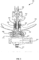
FIG. 3 depicts an advanced fire extinguisher system and its components in accordance with various embodiments; -
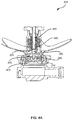
FIGs. 4A ,4B and4C depict a fire extinguisher which is activated upon command by releasing the elastic potential energy of a spring system to drive a broadhead cutter configured to rupture a hermetic burst disc in accordance with various embodiments; -
FIGs. 5A and 5B depict a whole burst disc and a pierced burst disc, respectively, in accordance with various embodiments; -
FIG. 6 depicts a broadhead burst disc cutter, in accordance with various embodiments; and -
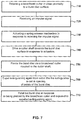
FIG. 7 depicts a method of actuating an advanced fire extinguisher system, in accordance with various embodiments. - The detailed description of exemplary embodiments herein makes reference to the accompanying drawings, which show exemplary embodiments by way of illustration and their best mode. While these exemplary embodiments are described in sufficient detail to enable those skilled in the art to practice the disclosure, it should be understood that other embodiments may be realized and that logical changes may be made without departing from the scope of the disclosure. Thus, the detailed description herein is presented for purposes of illustration only and not of limitation. For example, the steps recited in any of the method or process descriptions may be executed in any order and are not necessarily limited to the order presented. Furthermore, any reference to singular includes plural embodiments, and any reference to more than one component or step may include a singular embodiment or step.
- The present disclosure relates to fire extinguisher systems and their components. According to various embodiments and with reference to
FIG. 2 , aburst disc assembly 210 is ruptured from inside the fire extinguisher. In contrast to traditional systems, the explosive cartridge is replaced by abroadhead cutter 260 attached to an actuator. The actuator may be any desired actuator. For instance, the actuator may be acutter shaft 250 which will be put in motion by the release of the elastic potential energy of aspring system 220. A discharge head 320 (with brief reference toFIG. 3 ) may be used for interfacing to the aircraft plumbing/tubing to direct the agent to the desired location. A debris screen is not utilized in thedischarge head 320 because thebroadhead cutter 260 does not produce fragments when the fire extinguisher outletburst disc assembly 210 is ruptured. -
Figure 2 illustrates abroadhead cutter 260 activation mechanism andsystem 200 inside of a fire extinguisher in accordance with various embodiments.Fire extinguisher system 200 may be pyrotechnic free. The fire extinguisher may comprise aninternal volume area 230. Fire extinguishers can range in size 40 cubic inches to 2500+ cubic inches. The fire extinguisher may comprise aburst disc assembly 210. Theburst disc assembly 210 may be made from any suitable material configured to be pierced by thebroadhead cutter 260. Thebroadhead cutter 260 device may be attached to acutter shaft 250 which is driven downward (towards the center of the burst disc assembly 210) in response to the elastic potential energy being released from thespring system 220. Thespring system 220 releasingmechanism 240 may be, for example, a solenoid, a motor, such as a DC motor, a DC geared motor, a linear motor, a rotational solenoid using a ratcheted drive mechanism, and/or the like. - It should be noted that any structure located inside of the fire extinguisher associated with the support/stabilization of the mechanisms described below, as well as the routing of the electrical connections from the
electrical connector 310, with brief reference toFIG. 3 , to thespring system 220 releasingmechanism 240 are not shown in order to simplify the drawings. - According to various embodiments and with reference to
FIG. 3 , a pull rod 350 (aka a lock pin) is used to hold acollet 340 in a closed (forced outward) position to keep thespring system 220 compressed. Thecollet 340 is pushed outward so its outer flange engages a recess within thecutter shaft 250, so it is retained and cannot be moved downward (towards thedischarge head 320 by thecompressed spring system 220. Therefore, thespring system 220 is held in a compressed state by a portion of thecutter shaft 250. Thespring system 220 can be any type of a spring system, such as Bellville washers, helical/coil spring, and/or the like. - According to various embodiments and with continued reference to
FIG. 3 , alock pin spring 370 may be used to apply a positive pressure on thepull rod 350 so thepull rod 350 maintains thecollet 340 in a closed (force outward) position. Thelock pin spring 370 is utilized so thepull rod 350 is retained in its normal position during periods of shock and vibration. - According to various embodiments and with reference to
FIG. 4A , in a standby mode, thespring system 220 is held in compression by aface 255 of thecutter shaft 250. In the standby mode thebroadhead cutter 260 is in afirst position 410 in proximity to but not in contact with theburst disc assembly 210. The outer flange of thecollet 340 retains thecutter shaft 250 in aretaining position 460. Thepull rod 350 may be in anormal position 490 in standby mode holding thecollet 340 in a forced outward position. Should the extinguisher be activated, an electrical impulse may be sent via anelectrical connection 380 to the spring system release mechanism 240 (as depicted inFIG. 2 andFIG. 3 ). Springsystem release mechanism 240 pulls thepull rod 350 upward from its normal position in standby mode holding thecollet 340 in a forced outward position. - According to various embodiments and with reference to
FIG. 4B , in response to thepull rod 350 being pulled upward, as described above, an outer flange of thecollet 340 is no longer being held in place against the recess in thecutter shaft 250, so the force of thespring system 220 on thecutter shaft 250 is now free and/or available to push thecutter shaft 250 downward as thecollet 340 fingers flex radially inward with respect tocollet 340. The spring system may be in aflex position 465. As thecutter shaft 250 moves downward to adownward position 480, thebroadhead cutter 260 pierces theburst disc assembly 210. In this way, thebroadhead cutter 260 is in a piercingposition 420. The downward movement of thecutter shaft 250 and/orbroadhead cutter 260 is stopped by thestop ring 330. - According to various embodiments and with reference to
FIG. 4C , in response to thebroadhead cutter 260 penetrating theburst disc assembly 210, the pressure and extinguishing agent being expelled from within the fire extinguisher aid in the opening of the petals of theburst disc assembly 210 started by thebroadhead cutter 260. Stated another way theburst disc assembly 210 may petal out and split into a plurality of petal like shapes, such as four petals, when pierced by thebroadhead cutter 260. Moreover, thespring system 220 is in substantially fully activated and/orextended position 470. In this way,broadhead cutter 260 is in asecond position 430 where theburst disc assembly 210 is at least substantially opened by the pressure and extinguishing agent within the fire extinguisher.Figure 4C also illustrates that that thecutter shaft 250 in its fully extendeddownward position 480 has been stopped and retained by thestop ring 330 to keep thebroadhead cutter 260 from becoming a projectile. Thebroadhead cutter 260 starts the formation of the four petals, and the high pressure within the fire extinguisher completes the opening of the four petals to a substantially fully open position. The number of petals is related to the shape and design of thebroadhead cutter 260. - According to various embodiments and with reference to
FIG. 5A , a non-piercedburst disc assembly 210 is illustrated. According to various embodiments and with reference toFIG. 5B , a pierced and substantially opened burstdisc assembly 210 is illustrated. According to various embodiments and with reference toFIG. 6 , a singlepronged broadhead cutter 260 is depicted. Thebroadhead cutter 260 may take any form factor. Thebroadhead cutter 260 is configured for piercing theburst disc assembly 210. - According to various embodiments and with reference to
FIG. 7 , a method of actuating an extinguisher system is illustrated using a flow chart. The method may include retaining a broadhead cutter in close proximity to a burst disc surface (Step 710). The method may include receiving an impulse signal (Step 720). The method may include actuating a spring release mechanism in response to receiving the impulse signal (Step 730). The method may include driving a cutter shaft towards the burst disc surface in response to actuation (Step 740). The method may include piercing the burst disc via a broadhead cutter coupled to the cutter shaft (Step 750). Acollet 340 may be configured to retain the spring release mechanism in a standby position. The spring release mechanism may be actuated by an electrical actuation signal. Travel of thecutter shaft 250 may be stopped via physical contact with a stop ring. The pressure and extinguishing agent being expelled from within the fire extinguisher aid in opening of petals of the burst disc assembly 210 (Step 760). Theburst disc assembly 210 is configured to petal out in response to being pierced by the broadhead cutter 260 (Step 770). - Benefits, other advantages, and solutions to problems have been described herein with regard to specific embodiments. Furthermore, the connecting lines shown in the various figures contained herein are intended to represent exemplary functional relationships and/or physical couplings between the various elements. It should be noted that many alternative or additional functional relationships or physical connections may be present in a practical system. However, the benefits, advantages, solutions to problems, and any elements that may cause any benefit, advantage, or solution to occur or become more pronounced are not to be construed as critical, required, or essential features or elements of the disclosure. The scope of the disclosure is accordingly to be limited by nothing other than the appended claims, in which reference to an element in the singular is not intended to mean "one and only one" unless explicitly so stated, but rather "one or more."
- Systems, methods and apparatus are provided herein. In the detailed description herein, references to "various embodiments", "one embodiment", "an embodiment", "an example embodiment", etc., indicate that the embodiment described may include a particular feature, structure, or characteristic, but every embodiment may not necessarily include the particular feature, structure, or characteristic. Moreover, such phrases are not necessarily referring to the same embodiment. Further, when a particular feature, structure, or characteristic is described in connection with an embodiment, it is submitted that it is within the knowledge of one skilled in the art to affect such feature, structure, or characteristic in connection with other embodiments whether or not explicitly described. After reading the description, it will be apparent to one skilled in the relevant art(s) how to implement the disclosure in alternative embodiments. Different cross-hatching is used throughout the figures to denote different parts but not necessarily to denote the same or different materials.
Claims (15)
- A fire extinguisher system (200) comprising:a broadhead cutter (260) configured to pierce a burst disc (210);a broadhead cutter shaft (250) coupled to the broadhead cutter (260);a spring system (220) coupled to the broadhead cutter shaft (250); anda spring releasing mechanism (240) coupled to the spring system (220).
- The fire extinguisher system according to claim 1, wherein the spring releasing mechanism (240) is electrically activated.
- The fire extinguisher system according to claim 1 or 2, further comprising a collet (340) configured to retain the spring system (220) in a non-actuated position.
- The fire extinguisher system according to claim 3, further comprising a pull rod (350) configured to retain the collet (340) in a standby position.
- The fire extinguisher system according to any preceding claim, further comprising a stop ring (330) configured to retain the broadhead cutter shaft (250) within a discharge head (320).
- The fire extinguisher system according to any preceding claim, wherein the broadhead cutter (250) is configured to pierce the burst disc (210) in response to actuation of the spring system (220).
- The fire extinguisher system according to any preceding claim, wherein the fire extinguisher system (200) is pyrotechnic free.
- The fire extinguisher system according to any preceding claim, wherein the burst disc (210) is configured to petal out into a plurality of petal like shapes in response to piercing by the broadhead cutter (260).
- The fire extinguisher system according to claim 8, wherein an extinguishing agent expelled from within the fire extinguisher aids in opening of the plurality of petal like shapes of the burst disc (210).
- A method of actuating an extinguisher system (200) comprising:retaining a broadhead cutter (260) in close proximity to a burst disc surface;receiving an impulse signal;actuating a spring release mechanism (240) in response to receiving the impulse signal;driving a cutter shaft (250) towards the burst disc surface in response to actuation; andpiercing the burst disc surface via the broadhead cutter (260) coupled to the cutter shaft (250).
- The method of actuating an extinguisher system of claim 10, wherein a collet (340) retains the spring release mechanism (240) in a standby position.
- The method of actuating an extinguisher system of claim 10 or 11, wherein the spring release mechanism (240) is actuated by an electrical actuation signal.
- The method of actuating an extinguisher system of claim 10, 11 or 12, further comprising stopping travel of the cutter shaft (250) via physical contact with a stop ring (350).
- The method of actuating an extinguisher system of any of claims 10 to 13, further comprising expelling extinguishing agent from within the fire extinguisher to aid in opening of a plurality of petal like shapes of the burst disc surface.
- The method of actuating an extinguisher system of any of claims 10 to 14, wherein the burst disc surface is configured to petal out in response to piercing by the broadhead cutter (260).
Applications Claiming Priority (1)
| Application Number | Priority Date | Filing Date | Title |
|---|---|---|---|
| US14/602,811 US9861846B2 (en) | 2015-01-22 | 2015-01-22 | Spring-collet mechanism for activating a fire extinguisher |
Publications (1)
| Publication Number | Publication Date |
|---|---|
| EP3047879A1 true EP3047879A1 (en) | 2016-07-27 |
Family
ID=55177859
Family Applications (1)
| Application Number | Title | Priority Date | Filing Date |
|---|---|---|---|
| EP16152040.8A Withdrawn EP3047879A1 (en) | 2015-01-22 | 2016-01-20 | Spring-collet mechanism for activating a fire extinguisher |
Country Status (5)
| Country | Link |
|---|---|
| US (2) | US9861846B2 (en) |
| EP (1) | EP3047879A1 (en) |
| CN (2) | CN105816980B (en) |
| BR (1) | BR102016000924B1 (en) |
| CA (1) | CA2917061C (en) |
Families Citing this family (2)
| Publication number | Priority date | Publication date | Assignee | Title |
|---|---|---|---|---|
| CN108616221B (en) * | 2018-05-16 | 2020-10-02 | 广东中烟工业有限责任公司 | A fire-fighting fan actuator |
| CN112999547A (en) * | 2021-03-25 | 2021-06-22 | 国网山东省电力公司电力科学研究院 | Automatic fire extinguishing system and method for cable tunnel |
Citations (5)
| Publication number | Priority date | Publication date | Assignee | Title |
|---|---|---|---|---|
| GB2048062A (en) * | 1979-03-19 | 1980-12-10 | Rampart Eng Co Ltd | Operating Head for Fire Extinguisher |
| US5010911A (en) * | 1989-12-15 | 1991-04-30 | Wormald U.S., Inc. | Electromagnetic valve operator |
| RU2018332C1 (en) * | 1991-01-02 | 1994-08-30 | Российский научно-исследовательский институт горноспасательного дела | Shut-off actuating head of fire extinguisher |
| WO2010059282A2 (en) * | 2008-11-21 | 2010-05-27 | Fike Corporation | Impulse actuated valve |
| EP2965786A1 (en) * | 2014-07-11 | 2016-01-13 | Kidde Technologies, Inc. | Burst disk puncture pressure-imbalance actuator for a fire extinguisher |
Family Cites Families (28)
| Publication number | Priority date | Publication date | Assignee | Title |
|---|---|---|---|---|
| GB115898A (en) * | 1917-05-22 | 1918-05-22 | Sopwith Aviat Company Ltd | Improvements in Electric Couplings. |
| GB489485A (en) * | 1937-04-20 | 1938-07-27 | Pyrene Co Ltd | Improvements relating to fire-extinguishing apparatus |
| US2441011A (en) * | 1946-10-10 | 1948-05-04 | Pyrene Mfg Co | Discharge head for pressure fluid tanks |
| US3387662A (en) * | 1966-08-31 | 1968-06-11 | Frank A. Molgano Jr. | Fire extinguishing apparatus |
| GB2051335B (en) * | 1979-05-30 | 1983-01-26 | Legris | Remote-controlled valves |
| JPS6071084U (en) * | 1983-10-24 | 1985-05-20 | 星電器製造株式会社 | Connector with lock mechanism |
| US5230531A (en) * | 1990-10-22 | 1993-07-27 | Oea, Inc. | Gas generator ignition assembly using a projectile |
| US5735855A (en) * | 1996-10-25 | 1998-04-07 | Bradley; Gary W. | Automatic impact device |
| US6164383A (en) * | 1999-08-17 | 2000-12-26 | Thomas; Orrett H. | Fire extinguishing system for automotive vehicles |
| DE19955666A1 (en) * | 1999-08-26 | 2001-03-01 | Thomas Hohwieler | Connecting coaxial cable by pushing against lugs which bend, to penetrate insulation when cable withdrawn |
| FI113155B (en) * | 2002-01-17 | 2004-03-15 | Marioff Corp Oy | valve element |
| ITRM20030473A1 (en) * | 2003-10-15 | 2005-04-16 | Benedetto Fedeli | DRILLING DEVICE FOR A GAS BOTTLE |
| CN200939162Y (en) * | 2006-01-14 | 2007-08-29 | 王水良 | Disposable puncture outfit |
| JP4969300B2 (en) * | 2006-05-18 | 2012-07-04 | 英夫 吉田 | Fire extinguisher gas injector |
| WO2009050847A1 (en) * | 2007-10-19 | 2009-04-23 | Hideo Yoshida | Fire extinguisher gas ejector |
| CN201250288Y (en) * | 2008-07-23 | 2009-06-03 | 甘肃华鹭铝业有限公司 | Quick connector for aluminum cell crust breaking air cylinder and attacking head |
| CN201253436Y (en) * | 2008-08-20 | 2009-06-10 | 西安新竹防灾救生设备有限公司 | Diaphragm sealing type fire extinguishing device valve |
| US20120043096A1 (en) * | 2010-03-09 | 2012-02-23 | Butz James R | Microemulsion Fire Protection Device and Method |
| US20130014964A1 (en) * | 2010-03-30 | 2013-01-17 | Hideo Yoshida | Fire extinguisher gas ejector |
| US20140166913A1 (en) * | 2011-08-02 | 2014-06-19 | G.W. Lisk Company, Inc. | Pin Mechanism |
| EP2562875A1 (en) * | 2011-08-23 | 2013-02-27 | CEMBRE S.p.A. | Pulling device for pulling a punch in a contact bush |
| US9482255B2 (en) * | 2011-09-21 | 2016-11-01 | Bal Seal Engineering, Inc. | Multi-latching mechanisms and related methods |
| US9302128B2 (en) * | 2011-10-25 | 2016-04-05 | Kidde Technologies, Inc. | Automatic fire extinguishing system with internal dip tube |
| US9192798B2 (en) * | 2011-10-25 | 2015-11-24 | Kidde Technologies, Inc. | Automatic fire extinguishing system with gaseous and dry powder fire suppression agents |
| WO2014018332A1 (en) * | 2012-07-23 | 2014-01-30 | Carleton Technologies, Inc. | Inflator assembly adapted for manual or automatic inflation |
| CN203421247U (en) * | 2013-09-04 | 2014-02-05 | 北京泰和佳消防设备有限公司 | Remotely-controlled cylinder valve |
| US9309981B2 (en) * | 2013-10-18 | 2016-04-12 | Kidde Technologies, Inc. | Poppet valve with a frangible sealing disc for a pressure vessel |
| US9144699B1 (en) * | 2014-05-31 | 2015-09-29 | Chih-Chen Wang | Gas inlet structure for a fire extinguisher |
-
2015
- 2015-01-22 US US14/602,811 patent/US9861846B2/en not_active Expired - Fee Related
-
2016
- 2016-01-08 CA CA2917061A patent/CA2917061C/en active Active
- 2016-01-15 BR BR102016000924-3A patent/BR102016000924B1/en not_active IP Right Cessation
- 2016-01-20 EP EP16152040.8A patent/EP3047879A1/en not_active Withdrawn
- 2016-01-22 CN CN201610045381.4A patent/CN105816980B/en not_active Expired - Fee Related
- 2016-01-22 CN CN202011435927.XA patent/CN112494851B/en not_active Expired - Fee Related
-
2017
- 2017-12-01 US US15/829,285 patent/US10870026B2/en not_active Expired - Fee Related
Patent Citations (5)
| Publication number | Priority date | Publication date | Assignee | Title |
|---|---|---|---|---|
| GB2048062A (en) * | 1979-03-19 | 1980-12-10 | Rampart Eng Co Ltd | Operating Head for Fire Extinguisher |
| US5010911A (en) * | 1989-12-15 | 1991-04-30 | Wormald U.S., Inc. | Electromagnetic valve operator |
| RU2018332C1 (en) * | 1991-01-02 | 1994-08-30 | Российский научно-исследовательский институт горноспасательного дела | Shut-off actuating head of fire extinguisher |
| WO2010059282A2 (en) * | 2008-11-21 | 2010-05-27 | Fike Corporation | Impulse actuated valve |
| EP2965786A1 (en) * | 2014-07-11 | 2016-01-13 | Kidde Technologies, Inc. | Burst disk puncture pressure-imbalance actuator for a fire extinguisher |
Also Published As
| Publication number | Publication date |
|---|---|
| US20180085612A1 (en) | 2018-03-29 |
| CN112494851A (en) | 2021-03-16 |
| US20160213963A1 (en) | 2016-07-28 |
| CN112494851B (en) | 2022-08-12 |
| CA2917061C (en) | 2022-08-16 |
| CN105816980B (en) | 2021-01-01 |
| BR102016000924B1 (en) | 2021-11-16 |
| US10870026B2 (en) | 2020-12-22 |
| US9861846B2 (en) | 2018-01-09 |
| CN105816980A (en) | 2016-08-03 |
| BR102016000924A2 (en) | 2016-09-20 |
| CA2917061A1 (en) | 2016-07-22 |
Similar Documents
| Publication | Publication Date | Title |
|---|---|---|
| RU2493464C2 (en) | Valve with pulse actuator | |
| TW200946804A (en) | Single-action discharge valve | |
| EP2778486B1 (en) | Valve mechanism with frangible plug | |
| RU2311938C2 (en) | Valve | |
| CN105251170B (en) | rupture disk piercing pressure imbalance actuator for fire extinguishers | |
| CN111928742B (en) | Fuse for improving reliability of floor wiping explosion and self-destruction | |
| US10870026B2 (en) | Spring-collet mechanism for activating a fire extinguisher | |
| EP3023123B1 (en) | Poppet valve with a frangible sealing disc for a pressure vessel | |
| US9539452B2 (en) | Rapid pressure diffusion actuator for a fire extinguisher | |
| EP2965788B1 (en) | Motorized actuator for a fire extinguisher | |
| GB2581589A (en) | Firearm obstructer and methods of operating the same | |
| CN105508710B (en) | Frangible plug for use in a valve mechanism | |
| CN109386636A (en) | Actively with the difunctional pressure relief device that is passively combined | |
| UA138414U (en) | PYROBOLT |
Legal Events
| Date | Code | Title | Description |
|---|---|---|---|
| PUAI | Public reference made under article 153(3) epc to a published international application that has entered the european phase |
Free format text: ORIGINAL CODE: 0009012 |
|
| AK | Designated contracting states |
Kind code of ref document: A1 Designated state(s): AL AT BE BG CH CY CZ DE DK EE ES FI FR GB GR HR HU IE IS IT LI LT LU LV MC MK MT NL NO PL PT RO RS SE SI SK SM TR |
|
| AX | Request for extension of the european patent |
Extension state: BA ME |
|
| STAA | Information on the status of an ep patent application or granted ep patent |
Free format text: STATUS: REQUEST FOR EXAMINATION WAS MADE |
|
| 17P | Request for examination filed |
Effective date: 20170127 |
|
| RBV | Designated contracting states (corrected) |
Designated state(s): AL AT BE BG CH CY CZ DE DK EE ES FI FR GB GR HR HU IE IS IT LI LT LU LV MC MK MT NL NO PL PT RO RS SE SI SK SM TR |
|
| STAA | Information on the status of an ep patent application or granted ep patent |
Free format text: STATUS: EXAMINATION IS IN PROGRESS |
|
| 17Q | First examination report despatched |
Effective date: 20200821 |
|
| STAA | Information on the status of an ep patent application or granted ep patent |
Free format text: STATUS: THE APPLICATION IS DEEMED TO BE WITHDRAWN |
|
| 18D | Application deemed to be withdrawn |
Effective date: 20230705 |