EP3047787A1 - Endoscope system - Google Patents
Endoscope system Download PDFInfo
- Publication number
- EP3047787A1 EP3047787A1 EP14877628.9A EP14877628A EP3047787A1 EP 3047787 A1 EP3047787 A1 EP 3047787A1 EP 14877628 A EP14877628 A EP 14877628A EP 3047787 A1 EP3047787 A1 EP 3047787A1
- Authority
- EP
- European Patent Office
- Prior art keywords
- light
- side end
- face
- light source
- incident
- Prior art date
- Legal status (The legal status is an assumption and is not a legal conclusion. Google has not performed a legal analysis and makes no representation as to the accuracy of the status listed.)
- Withdrawn
Links
- 239000000835 fiber Substances 0.000 claims abstract description 103
- 230000003287 optical effect Effects 0.000 claims abstract description 80
- 238000005286 illumination Methods 0.000 claims abstract description 46
- 238000003780 insertion Methods 0.000 claims abstract description 35
- 230000037431 insertion Effects 0.000 claims abstract description 35
- 239000013307 optical fiber Substances 0.000 claims abstract description 12
- 230000004907 flux Effects 0.000 claims description 32
- 230000008859 change Effects 0.000 claims description 4
- 238000010586 diagram Methods 0.000 description 32
- 238000011084 recovery Methods 0.000 description 25
- 238000002834 transmittance Methods 0.000 description 16
- 230000004044 response Effects 0.000 description 14
- 230000005540 biological transmission Effects 0.000 description 3
- 230000007246 mechanism Effects 0.000 description 3
- 238000000034 method Methods 0.000 description 3
- PXHVJJICTQNCMI-UHFFFAOYSA-N Nickel Chemical compound [Ni] PXHVJJICTQNCMI-UHFFFAOYSA-N 0.000 description 2
- MCMNRKCIXSYSNV-UHFFFAOYSA-N Zirconium dioxide Chemical compound O=[Zr]=O MCMNRKCIXSYSNV-UHFFFAOYSA-N 0.000 description 2
- 239000011521 glass Substances 0.000 description 2
- 239000005304 optical glass Substances 0.000 description 2
- 230000005855 radiation Effects 0.000 description 2
- 230000000007 visual effect Effects 0.000 description 2
- 230000001133 acceleration Effects 0.000 description 1
- 230000001154 acute effect Effects 0.000 description 1
- 230000008901 benefit Effects 0.000 description 1
- 239000000919 ceramic Substances 0.000 description 1
- 230000001771 impaired effect Effects 0.000 description 1
- 230000002452 interceptive effect Effects 0.000 description 1
- 238000004519 manufacturing process Methods 0.000 description 1
- 229910052759 nickel Inorganic materials 0.000 description 1
- 230000009467 reduction Effects 0.000 description 1
- 239000007787 solid Substances 0.000 description 1
Images





Classifications
-
- A—HUMAN NECESSITIES
- A61—MEDICAL OR VETERINARY SCIENCE; HYGIENE
- A61B—DIAGNOSIS; SURGERY; IDENTIFICATION
- A61B1/00—Instruments for performing medical examinations of the interior of cavities or tubes of the body by visual or photographical inspection, e.g. endoscopes; Illuminating arrangements therefor
- A61B1/06—Instruments for performing medical examinations of the interior of cavities or tubes of the body by visual or photographical inspection, e.g. endoscopes; Illuminating arrangements therefor with illuminating arrangements
- A61B1/07—Instruments for performing medical examinations of the interior of cavities or tubes of the body by visual or photographical inspection, e.g. endoscopes; Illuminating arrangements therefor with illuminating arrangements using light-conductive means, e.g. optical fibres
-
- A—HUMAN NECESSITIES
- A61—MEDICAL OR VETERINARY SCIENCE; HYGIENE
- A61B—DIAGNOSIS; SURGERY; IDENTIFICATION
- A61B1/00—Instruments for performing medical examinations of the interior of cavities or tubes of the body by visual or photographical inspection, e.g. endoscopes; Illuminating arrangements therefor
- A61B1/00002—Operational features of endoscopes
- A61B1/00004—Operational features of endoscopes characterised by electronic signal processing
- A61B1/00006—Operational features of endoscopes characterised by electronic signal processing of control signals
-
- A—HUMAN NECESSITIES
- A61—MEDICAL OR VETERINARY SCIENCE; HYGIENE
- A61B—DIAGNOSIS; SURGERY; IDENTIFICATION
- A61B1/00—Instruments for performing medical examinations of the interior of cavities or tubes of the body by visual or photographical inspection, e.g. endoscopes; Illuminating arrangements therefor
- A61B1/00002—Operational features of endoscopes
- A61B1/00004—Operational features of endoscopes characterised by electronic signal processing
- A61B1/00009—Operational features of endoscopes characterised by electronic signal processing of image signals during a use of endoscope
-
- A—HUMAN NECESSITIES
- A61—MEDICAL OR VETERINARY SCIENCE; HYGIENE
- A61B—DIAGNOSIS; SURGERY; IDENTIFICATION
- A61B1/00—Instruments for performing medical examinations of the interior of cavities or tubes of the body by visual or photographical inspection, e.g. endoscopes; Illuminating arrangements therefor
- A61B1/00002—Operational features of endoscopes
- A61B1/00043—Operational features of endoscopes provided with output arrangements
- A61B1/00045—Display arrangement
-
- A—HUMAN NECESSITIES
- A61—MEDICAL OR VETERINARY SCIENCE; HYGIENE
- A61B—DIAGNOSIS; SURGERY; IDENTIFICATION
- A61B1/00—Instruments for performing medical examinations of the interior of cavities or tubes of the body by visual or photographical inspection, e.g. endoscopes; Illuminating arrangements therefor
- A61B1/00064—Constructional details of the endoscope body
- A61B1/00071—Insertion part of the endoscope body
- A61B1/0008—Insertion part of the endoscope body characterised by distal tip features
- A61B1/00096—Optical elements
-
- A—HUMAN NECESSITIES
- A61—MEDICAL OR VETERINARY SCIENCE; HYGIENE
- A61B—DIAGNOSIS; SURGERY; IDENTIFICATION
- A61B1/00—Instruments for performing medical examinations of the interior of cavities or tubes of the body by visual or photographical inspection, e.g. endoscopes; Illuminating arrangements therefor
- A61B1/00163—Optical arrangements
- A61B1/00165—Optical arrangements with light-conductive means, e.g. fibre optics
-
- A—HUMAN NECESSITIES
- A61—MEDICAL OR VETERINARY SCIENCE; HYGIENE
- A61B—DIAGNOSIS; SURGERY; IDENTIFICATION
- A61B1/00—Instruments for performing medical examinations of the interior of cavities or tubes of the body by visual or photographical inspection, e.g. endoscopes; Illuminating arrangements therefor
- A61B1/00163—Optical arrangements
- A61B1/00172—Optical arrangements with means for scanning
-
- A—HUMAN NECESSITIES
- A61—MEDICAL OR VETERINARY SCIENCE; HYGIENE
- A61B—DIAGNOSIS; SURGERY; IDENTIFICATION
- A61B1/00—Instruments for performing medical examinations of the interior of cavities or tubes of the body by visual or photographical inspection, e.g. endoscopes; Illuminating arrangements therefor
- A61B1/04—Instruments for performing medical examinations of the interior of cavities or tubes of the body by visual or photographical inspection, e.g. endoscopes; Illuminating arrangements therefor combined with photographic or television appliances
- A61B1/042—Instruments for performing medical examinations of the interior of cavities or tubes of the body by visual or photographical inspection, e.g. endoscopes; Illuminating arrangements therefor combined with photographic or television appliances characterised by a proximal camera, e.g. a CCD camera
-
- A—HUMAN NECESSITIES
- A61—MEDICAL OR VETERINARY SCIENCE; HYGIENE
- A61B—DIAGNOSIS; SURGERY; IDENTIFICATION
- A61B1/00—Instruments for performing medical examinations of the interior of cavities or tubes of the body by visual or photographical inspection, e.g. endoscopes; Illuminating arrangements therefor
- A61B1/06—Instruments for performing medical examinations of the interior of cavities or tubes of the body by visual or photographical inspection, e.g. endoscopes; Illuminating arrangements therefor with illuminating arrangements
- A61B1/0646—Instruments for performing medical examinations of the interior of cavities or tubes of the body by visual or photographical inspection, e.g. endoscopes; Illuminating arrangements therefor with illuminating arrangements with illumination filters
-
- A—HUMAN NECESSITIES
- A61—MEDICAL OR VETERINARY SCIENCE; HYGIENE
- A61B—DIAGNOSIS; SURGERY; IDENTIFICATION
- A61B1/00—Instruments for performing medical examinations of the interior of cavities or tubes of the body by visual or photographical inspection, e.g. endoscopes; Illuminating arrangements therefor
- A61B1/06—Instruments for performing medical examinations of the interior of cavities or tubes of the body by visual or photographical inspection, e.g. endoscopes; Illuminating arrangements therefor with illuminating arrangements
- A61B1/0661—Endoscope light sources
- A61B1/0669—Endoscope light sources at proximal end of an endoscope
Definitions
- the present invention relates to an endoscope system, and in particular to an endoscope system which scans an object to acquire an image.
- a scanning-type endoscope which does not have a solid image pickup device in a portion corresponding to the insertion portion described above, and a system configured being provided with the scanning-type endoscope are known.
- the system provided with the scanning-type endoscope is configured, for example, to two-dimensionally scan an object in a preset scan pattern by swinging a distal end portion of a light guiding fiber which guides light emitted from a light source portion, receive return light from the object by a light-receiving fiber and generate an image of the object based on the return light received by the light-receiving fiber.
- optical fibers there are, for example, some provided with such an optical characteristic that transmittance is reduced at time of being exposed to a radiation such as an X ray and that recovery of the reduction of the transmittance is accelerated by adding light having a relatively high intensity.
- Japanese Patent Application Laid-Open Publication No. S58-73332 discloses a technique for accelerating recovery of transmittance of an optical fiber which has been reduced by exposure to a radiation.
- Japanese Patent Application Laid-Open Publication No. S58-73332 discloses such a configuration that, in an endoscope, a transmittance of an optical glass fiber bundle for image transmission is recovered close to an initial transmittance (at time of manufacture) by providing a predetermined optical device (prism or mirror) for deflecting light emitted from a light emission end face of an optical fiber bundle for light transmission in an insertion portion and arranging the predetermined optical device at a position where the emitted light is caused to be incident on an image incident surface of the optical glass fiber bundle for image transmission.
- a predetermined optical device pris or mirror
- the present invention has been made in view of the situation described before, and an object is to provide an endoscope system capable of accelerating recovery of a transmittance of a light-receiving fiber without uselessly increasing a diameter of an insertion portion.
- An endoscope system of an aspect of the present invention includes: an elongated insertion portion insertable into a body cavity of a subject; a first light source portion provided outside the insertion portion and configured to supply illuminating light for illuminating an object in the body cavity of the subject; an illumination fiber provided in the insertion portion and configured to guide the illuminating light supplied from the first light source portion and emit the illuminating light to the object from an emission-end-side end face; a light-receiving fiber group provided in the insertion portion and configured being provided with one or more optical fibers receiving, by incident-end-side end faces, return light of the illuminating light emitted to the object from the emission-end-side end face of the illumination fiber; and an optical unit provided outside the insertion portion and configured to be capable of causing either the illuminating light supplied from the first light source portion or predetermined light different from the illuminating light, which is supplied from a second light source portion different from the first light source portion, to be incident on an emission-
- Figs. 1 to 5 relate to a first embodiment of the present invention.
- Fig. 1 is a diagram showing a configuration of main portions of an endoscope system according to the first embodiment.
- An endoscope system 1 is configured, for example, having a scanning-type endoscope 2 insertable into a body cavity of a subject, a body apparatus 3 to which the scanning-type endoscope 2 can be connected, a display device 4 capable of displaying an observed image and the like outputted from the body apparatus 3, and an input device 5 capable of inputting information and giving an instruction to the body apparatus 3, as shown in Fig. 1 .
- the input device 5 is not limited to such that is configured as a device different from the body apparatus 3 as shown in Fig. 1 but may be configured as an interface integrated with the body apparatus 3.
- the scanning-type endoscope 2 can be inserted into a body cavity of a subject and has an insertion portion 11 formed in an elongated cylindrical shape.
- a connector portion (not shown) for detachably connecting the scanning-type endoscope 2 to a connector receiving portion (not shown) of the body apparatus 3 is provided at a proximal end portion of the insertion portion 11.
- each of an illumination fiber 12 and a light-receiving fiber group 13 is inserted.
- the illumination fiber 12 is formed, for example, as an optical fiber which includes glass and the like, and is configured to be capable of guiding illuminating light supplied from the body apparatus 3 and emitting the guided illuminating light from a distal-end-side end face (arranged at the distal end portion of the insertion portion 11) (an emission-end-side end face) to an object.
- the light-receiving fiber group 13 is configured, for example, with a plurality of optical fibers bundled which include glass and the like, and configured to be capable of receiving return light of illuminating light emitted from the illumination fiber 12 to an object (reflected light generated by the illuminating light emitted from the illumination fiber 12 being reflected by the object) by a distal-end-side end face (an incident-end-side end face) and guiding the return light to the body apparatus 3. Further, the light-receiving fiber group 13 is configured to be capable of guiding light supplied from the body apparatus 3 in order to accelerate recovery of transmittance.
- An actuator portion 14 which is configured to swing an end portion including the distal-end-side end face (an emission-end-side end portion) of the illumination fiber 12 in response to a drive signal supplied from the body apparatus 3 is provided inside the insertion portion 11.
- each of the illumination fiber 12 and the actuator portion 14 is arranged, for example, so that a positional relationship shown in Fig. 2 is provided on a section vertical to a longitudinal axis direction of the scanning-type endoscope 2.
- Fig. 2 is a cross-sectional view for illustrating the configuration of the actuator portion provided in the scanning-type endoscope.
- a ferrule 41 as a joining member is arranged between the illumination fiber 12 and the actuator portion 14.
- the ferrule 41 is formed, for example, with zirconia (ceramic) or nickel.
- the ferrule 41 is formed as a quadrangular prism as shown in Fig. 2 and has side faces 42a and 42c vertical to an X axis direction (a right/left direction on the paper) and side faces 42b and 42d vertical to a Y axis direction (an upward/downward direction on the paper). Further, the illumination fiber 12 is fixed and arranged at a center of the ferrule 41. Note that the ferrule 41 may be formed in a shape other than the quadrangular prism.
- the actuator portion 14 has an actuator 14a arranged along the side face 42a, an actuator 14b arranged along the side face 42b, an actuator 14c arranged along the side face 42c and an actuator 14d arranged along the side face 42d.
- the actuators 14a and 14c are formed, for example, by piezoelectric elements and configured to be capable of swinging the end portion of the illumination fiber 12 which includes the distal-end-side end face along the X axis direction by being driven (expanding and contracting) in response to a drive signal supplied from the body apparatus 3.
- the actuators 14b and 14d are formed, for example, by piezoelectric elements and configured to be capable of swinging the end portion of the illumination fiber 12 which includes the distal-end-side end face along the Y axis direction by being driven (expanding and contracting) in response to a drive signal supplied from the body apparatus 3.
- the body apparatus 3 is configured having a light source portion 21, a scan driving portion 22, a light detecting portion 23, an image processing portion 24, a control portion 25, an optical unit 26, a lens LA provided near a light emission port (not shown) of the light source portion 21, a lens LB provided near a proximal-end-side end face (an incident-end-side end face) of the illumination fiber 12, a lens LC near a proximal-end-side end face (an emission-end-side end face) of the light-receiving fiber group 13 and a lens LD provided near a light incident port (not shown) of the light detecting portion 23 as shown in Fig. 1 .
- the light source portion 21 is configured to be capable of supplying (emitting from the light emission port) illuminating light for illuminating an object in a body cavity of a subject into which the insertion portion 11 is inserted.
- the light source portion 21 is provided with a laser light source for R light which emits R light, which is light in a red color gamut, a laser light source for G light which emits G light, which is light in a green color gamut, and a laser light source for B light which emits B light, which is light in a blue color gamut so as to supply white light (RGB light) obtained by combining lights emitted from the respective laser light sources as illuminating light.
- a laser light source for R light which emits R light, which is light in a red color gamut
- G light which emits G light
- B light which emits B light
- the light source portion 21 is configured, for example, to be capable of starting or stopping supply of illuminating light by switching between on and off states of each laser light source in response to control of the control portion 25.
- the scan driving portion 22 is, for example, provided with a drive circuit and the like and is configured to supply a drive signal for causing the actuator portion 14 to be driven, based on control of the control portion 25.
- the light detecting portion 23 is, for example, provided with a demultiplexer, an optical sensor and the like and is configured to separate return light caused to be incident (from the light incident port) into R (red), G (green) and B (blue) color components, generate color signals corresponding to lights separated according to the color components and output the color signals to the image processing portion 24.
- the image processing portion 24 is configured to be able to generate an observed image corresponding to color signals outputted from the light detecting portion 23 and outputting the observed image to the display device 4 based on control of the control portion 25. Further, the image processing portion 24 is configured to be capable of generating visual information such as character strings according to control of the control portion 25 and outputting the generated visual information to the display device 4.
- the control portion 25 is provided with a CPU and the like and is configured to be capable of performing various controls based on a control program read from a memory not shown.
- control portion 25 is configured, for example, to perform control for causing the end portion of the illumination fiber 12 which includes the distal-end-side end face to swing (along the predetermined track) so that an illumination position of illuminating light emitted from the insertion portion 11 draws a predetermined track, for the scan driving portion 22 based on the control program read from the memory not shown.
- control portion 25 is configured to be capable of performing various controls based on operations performed on the input device 5.
- control portion 25 is configured, for example, to perform control related to acceleration of recovery of transmittance of the light-receiving fiber group 13 when detecting that a predetermined switch SW (not shown) of the input device 5 is on. Note that details of such control will be described later.
- the optical unit 26 is arranged so as to be located midway on an optical path of illuminating light emitted via the lens LA from the light source portion 21 and located midway on an optical path of return light emitted via lens LC from the proximal-end-side end face of the light-receiving fiber group 13. Further, the optical unit 26 is configured, for example, having movable mirrors 261 and 262, and a luminous flux diameter changing portion 263 as shown in Fig. 3.
- Fig. 3 is a diagram for illustrating an example of the configuration of the optical unit according to the first embodiment.
- the movable mirror 261 is configured, for example, to move to a position where the movable mirror 261 can reflect illuminating light emitted via the lens LA to a luminous flux diameter changing portion 263 side (a predetermined position on an optical path from the lens LA to the lens LB) when the predetermined switch SW of the input device 5 is on, in response to control of the control portion 25.
- the movable mirror 261 is configured, for example, to be capable of moving to a position where the movable mirror 261 can cause the illuminating light emitted via the lens LA to be transmitted to a lens LB side (a predetermined position outside the optical path from the lens LA to the lens LB) when the predetermined switch SW of the input device 5 is off, in response to control of the control portion 25.
- the movable mirror 262 is configured, for example, to move to a position where the movable mirror 262 can reflect illuminating light emitted via the luminous flux diameter changing portion 263 to a lens LC side (a predetermined position on an optical path from the lens LC to the lens LD) when the predetermined switch SW of the input device 5 is on, in response to control of the control portion 25.
- the movable mirror 262 is configured, for example, to be capable of moving to a position where the movable mirror 262 can cause the illuminating light emitted via the lens LC to be transmitted to a lens LD side (a predetermined position outside the optical path from the lens LC to the lens LD) when the predetermined switch SW of the input device 5 is off, in response to control of the control portion 25.
- the luminous flux diameter changing portion 263 is arranged at a predetermined position on an optical path from the movable mirror 261 to the movable mirror 262. Further, the luminous flux diameter changing portion 263 is provided, for example, with a beam expander and is configured to change a luminous flux diameter of illuminating light caused to be incident via the movable mirror 261 when the predetermined switch SW is on so that the luminous flux diameter becomes a size matching a bundle diameter of the light-receiving fiber group 13 (expand the luminous flux diameter so that the luminous flux diameter becomes a same or substantially same size as the bundle diameter of the light-receiving fiber group 13) and emit the illuminating light to a movable mirror 262 side.
- the optical unit 26 can perform a switching operation for causing illuminating light emitted via the lens LA from the light source portion 21 to be incident either on the incident-end-side end face of the illumination fiber 12 or on the emission-end-side end face of the light-receiving fiber group 13 by moving the movable mirrors 261 and 262 in response to control of the control portion 25.
- the lens LA is configured, for example, being provided with an optical characteristic of emitting illuminating light supplied from the light source portion 21 as parallel light.
- the lens LB is configured, for example, being provided with an optical characteristic of condensing illuminating light (parallel light) emitted via the lens LA and the optical unit 26 and causing the illuminating light to be incident on the proximal-end-side end face of the illumination fiber 12.
- the lens LC is configured, for example, being provided with an optical characteristic of emitting return light emitted from the proximal-end-side end face of the light-receiving fiber group 13 as parallel light, and condensing illuminating light emitted via the optical unit 26 and causing the illuminating light to be incident on the proximal-end-side end face of the light-receiving fiber group 13.
- the lens LD is configured, for example, being provided with an optical characteristic of condensing return light (parallel light) emitted via the lens LC and the optical unit 26 and causing the return light to be incident on the light detecting portion 23.
- a user such as a surgeon makes an instruction for starting supply of illuminating light by operating the input device 5 in a state that the predetermined switch SW of the input device 5 is off, after connecting each portion of the endoscope system 1 and turning on power.
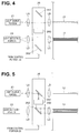
- the control portion 25 performs control for causing supply of illuminating light to be started, for the light source portion 21 based on the instruction made on the input device 5. Further, when detecting that the predetermined switch SW of the input device 5 is off, the control portion 25 performs control, for example, for causing the movable mirrors 261 and 262 of the optical unit 26 to move to positions as shown in Fig. 4.
- Fig. 4 is a diagram showing an example of an operation state of the optical unit according to the first embodiment.
- the user performs an operation for switching the predetermined switch SW of the input device 5 from off to on after confirming that illuminating light is being emitted from the insertion portion 11.
- Fig. 5 is a diagram showing an example of an operation state of the optical unit according to the first embodiment, which is different from the example in Fig. 4 .
- the endoscope system 1 As described above, by the endoscope system 1 according to the present embodiment, it is possible to accelerate recovery of transmittance of the light-receiving fiber group 13 without providing a dedicated optical member and the like in the insertion portion 11. Therefore, according to the present embodiment, it is possible to accelerate recovery of transmittance of a light-receiving fiber without uselessly increasing a diameter of an insertion portion.
- Figs. 6 to 13 relate to a second embodiment of the present invention.
- FIG. 6 is a diagram showing a configuration of main portions of an endoscope system according to the second embodiment.
- An endoscope system 1A is configured, for example, having a body apparatus 3A instead of the body apparatus 3 in the endoscope system 1, as shown in Fig. 6 . Further, the body apparatus 3A is configured having an optical unit 27 instead of the optical unit 26 in the body apparatus 3.
- the optical unit 27 is configured, for example, having rotating mirror mechanisms 271 and 272, and a luminous flux diameter changing portion 273 as shown in Fig. 7.
- Fig. 7 is a diagram for illustrating an example of a configuration of the optical unit according to the second embodiment.
- the rotating mirror mechanism 271 is configured, for example, having a motor 271A which rotates in response to control of the control portion 25, a rotating shaft 271B which transmits rotation force generated by rotation of the motor 271 A, a rotating plate 271C configured such that an end portion of the rotating shaft 271B is provided at a central part, as shown in Fig. 7 .
- the rotating plate 271C is formed, for example, being provided with a disk shape and is configured to rotate in conjunction with rotation of the rotating shaft 271B. Further, the rotating plate 271C is arranged so as to obliquely cross the optical path of illuminating light emitted via the lens LA (for example, so as to form an acute angle relative to the optical path of the illuminating light emitted via the lens LA). Furthermore, the rotating plate 271C is configured having an opening portion 271D and a mirror 271E.
- the opening portion 271 D is formed, for example, being provided with a C shape (an arc shape) as shown in Fig. 8 when seen from a direction indicated by an arrow AR1 in Fig. 7 and configured to cause illuminating light emitted via the lens LA to be transmitted.
- Fig. 8 is a diagram showing an example of a configuration of the rotating plate when seen from the direction indicated by the arrow AR1 in Fig. 7 .
- a transparent member capable of transmitting illuminating light emitted via the lens LA may be provided at the opening portion 271 D.
- the mirror 271E is formed, for example, being provided with such a shape (a disk shape) that covers both end portions of the C-shaped opening portion 271D and is arranged at a position where the mirror 271 E can reflect illuminating light emitted via the lens LA to a luminous flux diameter changing portion 273 side, as shown in Fig. 8 .
- the rotating mirror mechanism 272 is configured, for example, having a motor 272A which rotates in response to control of the control portion 25, a rotating shaft 272B which transmits rotation force generated by rotation of the motor 272A, a rotating plate 272C configured such that an end portion of the rotating shaft 272B is provided at a central part, as shown in Fig. 7 .
- the rotating plate 272C is formed, for example, being provided with a disk shape and is configured to rotate in conjunction with rotation of the rotating shaft 272B. Further, the rotating plate 272C is arranged so as to obliquely cross the optical path of return light emitted via the lens LC (for example, so as to form an obtuse angle relative to the optical path of the return light emitted via the lens LC). Furthermore, the rotating plate 272C is configured having an opening portion 272D and a mirror 272E, as shown in Fig. 7 .
- the opening portion 272D is formed, for example, being provided with a C shape (an arc shape) as shown in Fig. 9 when seen from a direction indicated by an arrow AR2 in Fig. 7 and configured to cause return light emitted via the lens LC to be transmitted.
- Fig. 9 is a diagram showing an example of the configuration of the rotating plate when seen from the direction indicated by the arrow AR2 in Fig. 7 .
- a transparent member capable of transmitting return light emitted via the lens LC may be provided at the opening portion 271D.
- the mirror 272E is formed, for example, being provided with such a shape (a disk shape) that covers both end portions of the C-shaped opening portion 272D and is arranged at a position where the mirror 272E can reflect illuminating light emitted via the luminous flux diameter changing portion 273 to a lens LC side, as shown in Fig. 9 .
- the luminous flux diameter changing portion 273 is arranged on an optical path LP from the mirror 271 E to the mirror 272E, which is an optical path temporarily formed accompanying rotation of the rotating plates 271C and 272C. Further, the luminous flux diameter changing portion 273 is provided, for example, with a beam expander and is configured to change a luminous flux diameter of illuminating light caused to be incident via the mirror 271E when the optical path LP is formed so that the luminous flux diameter becomes a size matching the bundle diameter of the light-receiving fiber group 13 (for example, expand the luminous flux diameter so that the luminous flux diameter becomes a same or substantially same size as the bundle diameter of the light-receiving fiber group 13) and emit the illuminating light to a mirror 272E side.
- a beam expander is configured to change a luminous flux diameter of illuminating light caused to be incident via the mirror 271E when the optical path LP is formed so that the luminous flux diameter becomes a size matching the bundle diameter of the light
- the optical unit 27 can perform a switching operation for causing illuminating light emitted via the lens LA from the light source portion 21 to be incident either on the incident-end-side end face of the illumination fiber 12 or on the emission-end-side end face of the light-receiving fiber group 13 by rotating the motors 271A and 272A in response to control of the control portion 25.
- control portion 25 of the present embodiment is configured to perform control for causing the optical path LP to be formed during a period until a predetermined time period elapses after scanning for acquiring observed images corresponding to a predetermined number of frames is performed. Note that, details of such control will be described later.
- the user makes an instruction for causing acquisition of an observed image by the scanning-type endoscope 2 and the body apparatus 3A to be started, by operating the input device 5 after connecting each portion of the endoscope system 1 A and turning on power.
- control portion 25 When detecting that the instruction for causing acquisition of an observed image by the scanning-type endoscope 2 and the body apparatus 3A to be started has been made, the control portion 25 performs control for causing supply of illuminating light to be started, for the light source portion 21, and performs control for causing the end portion of the illumination fiber 12 which includes the distal-end-side end face to swing so that an illumination position of illuminating light emitted from the insertion portion 11 draws a spiral-shaped track, for the scan driving portion 22.
- control portion 25 performs control for causing illuminating light supplied from the light source portion 21 to be incident on the proximal-end-side end face of the illumination fiber 12 and also causing return light emitted from the proximal-end-side end face of the light-receiving fiber group 13 to be incident on the light detecting portion 23, for the optical unit 27.
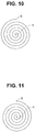
- control portion 25 performs control, for example, for causing the end portion of the illumination fiber 12 which includes the distal-end-side end face to swing along a first spiral-shaped track from a center point A toward an outermost point B in Fig. 10 and, after that, causing the end portion to swing along a second spiral-shaped track from the outermost point B toward the center point A in Fig. 11 .
- the control portion 25 adjusts rotation speed and the like of the motors 271A and 272A so that illuminating light emitted via the lens LA is transmitted through the opening portion 271D, and return light emitted via the lens LC is transmitted through the opening portion 272D while causing the end portion of the illumination fiber 12 which includes the distal-end-side end face to swing along the first spiral-shaped track or the second spiral-shaped track.
- Fig. 10 is a diagram showing an example of a case where, in a scan for acquiring an observed image of an object, the scan is performed so as to advance from the center point A to the outermost point B of the spiral-shaped track.
- Fig. 11 is a diagram showing an example of a case where, in a scan for acquiring an observed image of an object, the scan is performed so as to advance from the outermost point B to the center point A of the spiral-shaped track.
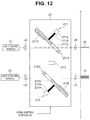
- control portion 25 for example, illuminating light emitted from the light source portion 21 during a period during which the end portion of the illumination fiber 12 which includes the distal-end-side end face is caused to swing along a spiral-shaped track is caused to be incident on the proximal-end-side end face of the illumination fiber 12 after being transmitted through the lens LA, the opening portion 271 D and the lens LB sequentially, as shown in Fig. 12 .
- Fig. 12 is a diagram showing an example of an operation state of the optical unit according to the second embodiment.
- the image processing portion 24 generates a first observed image corresponding to one frame using color signals outputted from the light detecting portion 23 during a period during which the illumination fiber 12 is caused to swing along the first spiral-shaped track illustrated in Fig. 10 , and outputs the first observed image to the display device 4, based on control of the control portion 25. Further, the image processing portion 24 generates a second observed image corresponding to one frame using color signals outputted from the light detecting portion 23 during a period during which the illumination fiber 12 is caused to swing along the second spiral-shaped track illustrated in Fig. 11 , and outputs the second observed image to the display device 4, based on control of the control portion 25.
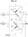
- control portion 25 when detecting that the instruction for causing acquisition of an observed image by the scanning-type endoscope 2 and the body apparatus 3A to be started has been made, the control portion 25 performs control for causing illuminating light supplied from the light source portion 21 to be incident on the proximal-end-side end face of the light-receiving fiber group 13, for the optical unit 27 during the period until the predetermined time period elapses after scanning for acquiring observed images corresponding to a predetermined number of frames is performed.
- control portion 25 performs control for causing the end portion of the illumination fiber 12 which includes the distal-end-side end face to stop moving at the center point A, for the scan driving portion 22, and adjusts the rotation speed and the like of the motors 271 A and 272A so that the optical path LP is formed.
- Fig. 13 is a diagram showing an example of an operation state of the optical unit according to the second embodiment.
- the image processing portion 24 stops an operation related to generation and output of an observed image during the period of the predetermined time period PT based on control of the control portion 25.
- the endoscope system 1A it is possible to accelerate recovery of transmittance of the light-receiving fiber group 13 without providing a dedicated optical member and the like in the insertion portion 11. Therefore, according to the present embodiment, it is possible to accelerate recovery of transmittance of a light-receiving fiber without uselessly increasing a diameter of the insertion portion.
- the endoscope system 1A it is possible to cause illuminating light emitted from the light source portion 21 during the period of the predetermined time period PT which does not contribute to acquisition of an observed image to be incident on the light-receiving fiber group 13. Therefore, by the endoscope system 1A according to the present embodiment, it is possible to accelerate recovery of transmittance of the light-receiving fiber group 13 without interfering with generation of an observed image by the image processing portion 24.
- Figs. 14 to 17 relate to a third embodiment of the present invention.
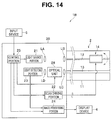
- FIG. 14 is a diagram showing a configuration of main portions of an endoscope system according to the third embodiment.
- An endoscope system 1B is configured, for example, having a body apparatus 3B instead of the body apparatus 3 in the endoscope system 1, as shown in Fig. 14 . Further, the body apparatus 3B is configured having an optical unit 28 instead of the optical unit 26 in the body apparatus 3.
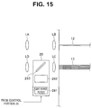
- the optical unit 28 is configured, for example, having a light source portion 281, a luminous flux diameter changing portion 282 and a dichroic mirror 283 as shown in Fig. 15.
- Fig. 15 is a diagram for illustrating an example of a configuration of the optical unit according to the third embodiment.
- the light source portion 281 is configured to be capable of supplying predetermined light provided with a wavelength band which does not overlap with a wavelength band of illuminating light emitted from the light source portion 21 (hereinafter, also referred to as recovery accelerating light) to the luminous flux diameter changing portion 282. Further, the light source portion 281 is configured to be capable of starting or stopping supply of the recovery accelerating light in response to control of the control portion 25.
- the luminous flux diameter changing portion 282 is arranged at a predetermined position on an optical path from the light source portion 281 to the dichroic mirror 283. Further, the luminous flux diameter changing portion 282 is provided, for example, with a beam expander and is configured to change a luminous flux diameter of recovery accelerating light emitted from the light source portion 281 so that the luminous flux diameter becomes a size matching a bundle diameter of the light-receiving fiber group 13 (for example, to expand the luminous flux diameter so that the luminous flux diameter becomes a same or substantially same size as the bundle diameter of the light-receiving fiber group 13) and emit the illuminating light to a dichroic mirror 283 side.
- a beam expander is configured to change a luminous flux diameter of recovery accelerating light emitted from the light source portion 281 so that the luminous flux diameter becomes a size matching a bundle diameter of the light-receiving fiber group 13 (for example, to expand the luminous flux diameter so that the luminous flux diameter becomes a
- the dichroic mirror 283 is configured, for example, being provided with an optical characteristic capable of reflecting recovery accelerating light emitted via the luminous flux diameter changing portion 282 to a lens LC side and causing return light emitted via the lens LC to be transmitted to a lens LD side.
- the optical unit 28 can cause recovery accelerating light supplied from the light source portion 281 to be incident on the emission-end-side end face of the light-receiving fiber group 13 by causing the light source portion 281 to operate in response to control of the control portion 25.
- the lens LC of the present embodiment is configured, for example, being provided with an optical characteristic of emitting return light emitted from the proximal-end-side end face of the light-receiving fiber group 13 as parallel light, and condensing recovery accelerating light supplied from the optical unit 28 and causing the recovery accelerating light to be incident on the proximal-end-side end face of the light-receiving fiber group 13.
- the user makes an instruction for causing acquisition of an observed image by the scanning-type endoscope 2 and the body apparatus 3B to be started, by operating the input device 5 after connecting each portion of the endoscope system 1B and turning on power.
- the control portion 25 When detecting that the instruction for causing acquisition of an observed image by the scanning-type endoscope 2 and the body apparatus 3B to be started has been made, the control portion 25 performs control for causing supply of illuminating light to be started, for the light source portion 21, performs control for causing supply of recovery accelerating light from the light source portion 281 to be started, for the optical unit 28, and performs control for causing the end portion of the illumination fiber 12 which includes the distal-end-side end face to swing so that an illumination position of illuminating light emitted from the insertion portion 11 draws a spiral-shaped track, for the scan driving portion 22.
- control portion 25 for example, illuminating light emitted from the light source portion 21 is caused to be incident on the proximal-end-side end face of the illumination fiber 12 after being transmitted through the lens LA and the lens LB sequentially, as shown in Fig. 16 .
- Fig. 16 is a diagram showing an example of an operation state of the optical unit according to the third embodiment.
- an optical filter 29 configured to intercept a wavelength band component of recovery accelerating light caused to be incident from the proximal-end-side end face of the light-receiving fiber group 13 may be provided on the distal-end-side end face of the light-receiving fiber group 13 so that the recovery accelerating light caused to be incident on the light-receiving fiber group 13 via the lens LD is not emitted to an outside of the insertion portion 11 (an object illuminated by illuminating light emitted from the illumination fiber 12), as shown in Fig. 17.
- Fig. 17 is a diagram showing an example of a setup position of the filter which can be used together with the optical unit according to the third embodiment.
- the endoscope system 1B it is possible to accelerate recovery of transmittance of the light-receiving fiber group 13 without providing a dedicated optical member and the like in the insertion portion 11. Therefore, according to the present embodiment, it is possible to accelerate recovery of transmittance of a light-receiving fiber without uselessly increasing a diameter of an insertion portion.
- the endoscope system 1B it is possible to cause return light emitted from the light-receiving fiber group 13 to be incident on the light detecting portion 23 while causing recovery accelerating light emitted from the optical unit 28 to be incident on the light-receiving fiber group 13. Therefore, by the endoscope system 1B according to the present embodiment, it is possible to accelerate recovery of transmittance of the light-receiving fiber group 13 without discontinuing display of an observed image on the display device 4.
Landscapes
- Health & Medical Sciences (AREA)
- Life Sciences & Earth Sciences (AREA)
- Surgery (AREA)
- Engineering & Computer Science (AREA)
- Optics & Photonics (AREA)
- Physics & Mathematics (AREA)
- Biophysics (AREA)
- General Health & Medical Sciences (AREA)
- Pathology (AREA)
- Radiology & Medical Imaging (AREA)
- Veterinary Medicine (AREA)
- Biomedical Technology (AREA)
- Heart & Thoracic Surgery (AREA)
- Medical Informatics (AREA)
- Molecular Biology (AREA)
- Animal Behavior & Ethology (AREA)
- Nuclear Medicine, Radiotherapy & Molecular Imaging (AREA)
- Public Health (AREA)
- Signal Processing (AREA)
- Instruments For Viewing The Inside Of Hollow Bodies (AREA)
- Endoscopes (AREA)
Abstract
Description
- The present invention relates to an endoscope system, and in particular to an endoscope system which scans an object to acquire an image.
- For endoscopes in a medical field, various techniques for reducing a diameter of an insertion portion inserted into a body cavity of a subject have been proposed in order to reduce a burden on the subject. As an example of such techniques, a scanning-type endoscope which does not have a solid image pickup device in a portion corresponding to the insertion portion described above, and a system configured being provided with the scanning-type endoscope are known.
- More specifically, the system provided with the scanning-type endoscope is configured, for example, to two-dimensionally scan an object in a preset scan pattern by swinging a distal end portion of a light guiding fiber which guides light emitted from a light source portion, receive return light from the object by a light-receiving fiber and generate an image of the object based on the return light received by the light-receiving fiber.
- On the other hand, among optical fibers, there are, for example, some provided with such an optical characteristic that transmittance is reduced at time of being exposed to a radiation such as an X ray and that recovery of the reduction of the transmittance is accelerated by adding light having a relatively high intensity.
- For example, Japanese Patent Application Laid-Open Publication No.
S58-73332 - More specifically, Japanese Patent Application Laid-Open Publication No.
S58-73332 - In a case of simply applying the configuration disclosed in Japanese Patent Application Laid-Open Publication No.
S58-73332 - The present invention has been made in view of the situation described before, and an object is to provide an endoscope system capable of accelerating recovery of a transmittance of a light-receiving fiber without uselessly increasing a diameter of an insertion portion.
- An endoscope system of an aspect of the present invention includes: an elongated insertion portion insertable into a body cavity of a subject; a first light source portion provided outside the insertion portion and configured to supply illuminating light for illuminating an object in the body cavity of the subject; an illumination fiber provided in the insertion portion and configured to guide the illuminating light supplied from the first light source portion and emit the illuminating light to the object from an emission-end-side end face; a light-receiving fiber group provided in the insertion portion and configured being provided with one or more optical fibers receiving, by incident-end-side end faces, return light of the illuminating light emitted to the object from the emission-end-side end face of the illumination fiber; and an optical unit provided outside the insertion portion and configured to be capable of causing either the illuminating light supplied from the first light source portion or predetermined light different from the illuminating light, which is supplied from a second light source portion different from the first light source portion, to be incident on an emission-end-side end face of the light-receiving fiber group.
-
-
Fig. 1 is a diagram showing a configuration of main portions of an endoscope system according to a first embodiment; -
Fig. 2 is a cross-sectional view for illustrating a configuration of an actuator portion provided in a scanning-type endoscope; -
Fig. 3 is a diagram for illustrating an example of a configuration of an optical unit according to the first embodiment; -
Fig. 4 is a diagram showing an example of an operation state of the optical unit according to the first embodiment; -
Fig. 5 is a diagram showing an example of the operation state of the optical unit according to the first embodiment different from the example inFig. 4 ; -
Fig. 6 is a diagram showing a configuration of main portions of an endoscope system according to a second embodiment; -
Fig. 7 is a diagram for illustrating an example of a configuration of an optical unit according to the second embodiment; -
Fig. 8 is a diagram showing an example of a configuration of a rotating plate when the rotating plate is seen from a direction indicated by an arrow AR1 inFig. 7 ; -
Fig. 9 is a diagram showing an example of a configuration of a rotating plate when the rotating plate is seen from a direction indicated by an arrow AR2 inFig. 7 ; -
Fig. 10 is a diagram showing an example of a case where, in a scan for acquiring an observed image of an object, the scan is performed so as to advance from a center point A of a spiral-shaped track to an outermost point B; -
Fig. 11 is a diagram showing an example of a case where, in a scan for acquiring an observed image of an object, the scan is performed so as to advance from the outermost point B to the center point A; -
Fig. 12 is a diagram showing an example of an operation state of the optical unit according to the second embodiment; -
Fig. 13 is a diagram showing an example of the operation state of the optical unit according to the second embodiment different from the example inFig. 12 ; -
Fig. 14 is a diagram showing a configuration of main portions of an endoscope system according to a third embodiment; -
Fig. 15 is a diagram for illustrating an example of a configuration of an optical unit according to the third embodiment; -
Fig. 16 is a diagram showing an example of an operation state of the optical unit according to the third embodiment; and -
Fig. 17 is a diagram showing an example of a setup position of a filter which can be used together with the optical unit according to the third embodiment. - Embodiments of the present invention will be described below with reference to drawings.
-
Figs. 1 to 5 relate to a first embodiment of the present invention.Fig. 1 is a diagram showing a configuration of main portions of an endoscope system according to the first embodiment. - An
endoscope system 1 is configured, for example, having a scanning-type endoscope 2 insertable into a body cavity of a subject, abody apparatus 3 to which the scanning-type endoscope 2 can be connected, adisplay device 4 capable of displaying an observed image and the like outputted from thebody apparatus 3, and aninput device 5 capable of inputting information and giving an instruction to thebody apparatus 3, as shown inFig. 1 . Note that theinput device 5 is not limited to such that is configured as a device different from thebody apparatus 3 as shown inFig. 1 but may be configured as an interface integrated with thebody apparatus 3. - The scanning-
type endoscope 2 can be inserted into a body cavity of a subject and has aninsertion portion 11 formed in an elongated cylindrical shape. - A connector portion (not shown) for detachably connecting the scanning-
type endoscope 2 to a connector receiving portion (not shown) of thebody apparatus 3 is provided at a proximal end portion of theinsertion portion 11. - In a part from the proximal end portion to a distal end portion inside the
insertion portion 11, each of anillumination fiber 12 and a light-receivingfiber group 13 is inserted. - The
illumination fiber 12 is formed, for example, as an optical fiber which includes glass and the like, and is configured to be capable of guiding illuminating light supplied from thebody apparatus 3 and emitting the guided illuminating light from a distal-end-side end face (arranged at the distal end portion of the insertion portion 11) (an emission-end-side end face) to an object. - The light-receiving
fiber group 13 is configured, for example, with a plurality of optical fibers bundled which include glass and the like, and configured to be capable of receiving return light of illuminating light emitted from theillumination fiber 12 to an object (reflected light generated by the illuminating light emitted from theillumination fiber 12 being reflected by the object) by a distal-end-side end face (an incident-end-side end face) and guiding the return light to thebody apparatus 3. Further, the light-receivingfiber group 13 is configured to be capable of guiding light supplied from thebody apparatus 3 in order to accelerate recovery of transmittance. - An
actuator portion 14 which is configured to swing an end portion including the distal-end-side end face (an emission-end-side end portion) of theillumination fiber 12 in response to a drive signal supplied from thebody apparatus 3 is provided inside theinsertion portion 11. - On the other hand, each of the
illumination fiber 12 and theactuator portion 14 is arranged, for example, so that a positional relationship shown inFig. 2 is provided on a section vertical to a longitudinal axis direction of the scanning-type endoscope 2.Fig. 2 is a cross-sectional view for illustrating the configuration of the actuator portion provided in the scanning-type endoscope. - As shown in
Fig. 2 , aferrule 41 as a joining member is arranged between theillumination fiber 12 and theactuator portion 14. - More specifically, the
ferrule 41 is formed, for example, with zirconia (ceramic) or nickel. - The
ferrule 41 is formed as a quadrangular prism as shown inFig. 2 and hasside faces side faces illumination fiber 12 is fixed and arranged at a center of theferrule 41. Note that theferrule 41 may be formed in a shape other than the quadrangular prism. - As shown in
Fig. 2 , theactuator portion 14 has an actuator 14a arranged along theside face 42a, anactuator 14b arranged along theside face 42b, anactuator 14c arranged along theside face 42c and anactuator 14d arranged along theside face 42d. - The
actuators 14a and 14c are formed, for example, by piezoelectric elements and configured to be capable of swinging the end portion of theillumination fiber 12 which includes the distal-end-side end face along the X axis direction by being driven (expanding and contracting) in response to a drive signal supplied from thebody apparatus 3. - The
actuators illumination fiber 12 which includes the distal-end-side end face along the Y axis direction by being driven (expanding and contracting) in response to a drive signal supplied from thebody apparatus 3. - On the other hand, the
body apparatus 3 is configured having alight source portion 21, ascan driving portion 22, alight detecting portion 23, animage processing portion 24, acontrol portion 25, anoptical unit 26, a lens LA provided near a light emission port (not shown) of thelight source portion 21, a lens LB provided near a proximal-end-side end face (an incident-end-side end face) of theillumination fiber 12, a lens LC near a proximal-end-side end face (an emission-end-side end face) of the light-receivingfiber group 13 and a lens LD provided near a light incident port (not shown) of thelight detecting portion 23 as shown inFig. 1 . - The
light source portion 21 is configured to be capable of supplying (emitting from the light emission port) illuminating light for illuminating an object in a body cavity of a subject into which theinsertion portion 11 is inserted. - More specifically, for example, the
light source portion 21 is provided with a laser light source for R light which emits R light, which is light in a red color gamut, a laser light source for G light which emits G light, which is light in a green color gamut, and a laser light source for B light which emits B light, which is light in a blue color gamut so as to supply white light (RGB light) obtained by combining lights emitted from the respective laser light sources as illuminating light. - Further, the
light source portion 21 is configured, for example, to be capable of starting or stopping supply of illuminating light by switching between on and off states of each laser light source in response to control of thecontrol portion 25. - The
scan driving portion 22 is, for example, provided with a drive circuit and the like and is configured to supply a drive signal for causing theactuator portion 14 to be driven, based on control of thecontrol portion 25. - The
light detecting portion 23 is, for example, provided with a demultiplexer, an optical sensor and the like and is configured to separate return light caused to be incident (from the light incident port) into R (red), G (green) and B (blue) color components, generate color signals corresponding to lights separated according to the color components and output the color signals to theimage processing portion 24. - The
image processing portion 24 is configured to be able to generate an observed image corresponding to color signals outputted from thelight detecting portion 23 and outputting the observed image to thedisplay device 4 based on control of thecontrol portion 25. Further, theimage processing portion 24 is configured to be capable of generating visual information such as character strings according to control of thecontrol portion 25 and outputting the generated visual information to thedisplay device 4. - The
control portion 25 is provided with a CPU and the like and is configured to be capable of performing various controls based on a control program read from a memory not shown. - More specifically, the
control portion 25 is configured, for example, to perform control for causing the end portion of theillumination fiber 12 which includes the distal-end-side end face to swing (along the predetermined track) so that an illumination position of illuminating light emitted from theinsertion portion 11 draws a predetermined track, for thescan driving portion 22 based on the control program read from the memory not shown. - Further, the
control portion 25 is configured to be capable of performing various controls based on operations performed on theinput device 5. - More specifically, the
control portion 25 is configured, for example, to perform control related to acceleration of recovery of transmittance of the light-receivingfiber group 13 when detecting that a predetermined switch SW (not shown) of theinput device 5 is on. Note that details of such control will be described later. - As shown in
Fig. 2 , theoptical unit 26 is arranged so as to be located midway on an optical path of illuminating light emitted via the lens LA from thelight source portion 21 and located midway on an optical path of return light emitted via lens LC from the proximal-end-side end face of the light-receivingfiber group 13. Further, theoptical unit 26 is configured, for example, havingmovable mirrors diameter changing portion 263 as shown inFig. 3. Fig. 3 is a diagram for illustrating an example of the configuration of the optical unit according to the first embodiment. - The
movable mirror 261 is configured, for example, to move to a position where themovable mirror 261 can reflect illuminating light emitted via the lens LA to a luminous fluxdiameter changing portion 263 side (a predetermined position on an optical path from the lens LA to the lens LB) when the predetermined switch SW of theinput device 5 is on, in response to control of thecontrol portion 25. Further, themovable mirror 261 is configured, for example, to be capable of moving to a position where themovable mirror 261 can cause the illuminating light emitted via the lens LA to be transmitted to a lens LB side (a predetermined position outside the optical path from the lens LA to the lens LB) when the predetermined switch SW of theinput device 5 is off, in response to control of thecontrol portion 25. - The
movable mirror 262 is configured, for example, to move to a position where themovable mirror 262 can reflect illuminating light emitted via the luminous fluxdiameter changing portion 263 to a lens LC side (a predetermined position on an optical path from the lens LC to the lens LD) when the predetermined switch SW of theinput device 5 is on, in response to control of thecontrol portion 25. Further, themovable mirror 262 is configured, for example, to be capable of moving to a position where themovable mirror 262 can cause the illuminating light emitted via the lens LC to be transmitted to a lens LD side (a predetermined position outside the optical path from the lens LC to the lens LD) when the predetermined switch SW of theinput device 5 is off, in response to control of thecontrol portion 25. - The luminous flux
diameter changing portion 263 is arranged at a predetermined position on an optical path from themovable mirror 261 to themovable mirror 262. Further, the luminous fluxdiameter changing portion 263 is provided, for example, with a beam expander and is configured to change a luminous flux diameter of illuminating light caused to be incident via themovable mirror 261 when the predetermined switch SW is on so that the luminous flux diameter becomes a size matching a bundle diameter of the light-receiving fiber group 13 (expand the luminous flux diameter so that the luminous flux diameter becomes a same or substantially same size as the bundle diameter of the light-receiving fiber group 13) and emit the illuminating light to amovable mirror 262 side. - That is, the
optical unit 26 can perform a switching operation for causing illuminating light emitted via the lens LA from thelight source portion 21 to be incident either on the incident-end-side end face of theillumination fiber 12 or on the emission-end-side end face of the light-receivingfiber group 13 by moving themovable mirrors control portion 25. - The lens LA is configured, for example, being provided with an optical characteristic of emitting illuminating light supplied from the
light source portion 21 as parallel light. - The lens LB is configured, for example, being provided with an optical characteristic of condensing illuminating light (parallel light) emitted via the lens LA and the
optical unit 26 and causing the illuminating light to be incident on the proximal-end-side end face of theillumination fiber 12. - The lens LC is configured, for example, being provided with an optical characteristic of emitting return light emitted from the proximal-end-side end face of the light-receiving
fiber group 13 as parallel light, and condensing illuminating light emitted via theoptical unit 26 and causing the illuminating light to be incident on the proximal-end-side end face of the light-receivingfiber group 13. - The lens LD is configured, for example, being provided with an optical characteristic of condensing return light (parallel light) emitted via the lens LC and the
optical unit 26 and causing the return light to be incident on thelight detecting portion 23. - Next, an operation of the
endoscope system 1 according to the present embodiment will be described. - A user such as a surgeon makes an instruction for starting supply of illuminating light by operating the
input device 5 in a state that the predetermined switch SW of theinput device 5 is off, after connecting each portion of theendoscope system 1 and turning on power. - The
control portion 25 performs control for causing supply of illuminating light to be started, for thelight source portion 21 based on the instruction made on theinput device 5. Further, when detecting that the predetermined switch SW of theinput device 5 is off, thecontrol portion 25 performs control, for example, for causing themovable mirrors optical unit 26 to move to positions as shown inFig. 4. Fig. 4 is a diagram showing an example of an operation state of the optical unit according to the first embodiment. - Then, by the control of the
control portion 25 as described above, illuminating light emitted from thelight source portion 21 when the predetermined switch SW is off is caused to be incident on the proximal-end-side end face of theillumination fiber 12 after being transmitted through the lens LA and the lens LB sequentially. Then, by the control of thecontrol portion 25 as described above, return light emitted from the proximal-end-side end face of the light-receivingfiber group 13 when the predetermined switch SW is off is caused to be incident on thelight detecting portion 23 after being transmitted through the lens LC and the lens LD sequentially. - On the other hand, the user performs an operation for switching the predetermined switch SW of the
input device 5 from off to on after confirming that illuminating light is being emitted from theinsertion portion 11. - When detecting that the predetermined switch SW of the
input device 5 is on, thecontrol portion 25 performs control, for example, for causing themovable mirrors optical unit 26 to move to positions as shown inFig. 5. Fig. 5 is a diagram showing an example of an operation state of the optical unit according to the first embodiment, which is different from the example inFig. 4 . - Then, by the control of the
control portion 25 as described above, illuminating light emitted from thelight source portion 21 when the predetermined switch SW is on is caused to be incident on the proximal-end-side end face of the light-receivingfiber group 13 after being transmitted through the lens LA, themovable mirror 261, the luminous fluxdiameter changing portion 263, themovable mirror 262 and the lens LC sequentially. - As described above, by the
endoscope system 1 according to the present embodiment, it is possible to accelerate recovery of transmittance of the light-receivingfiber group 13 without providing a dedicated optical member and the like in theinsertion portion 11. Therefore, according to the present embodiment, it is possible to accelerate recovery of transmittance of a light-receiving fiber without uselessly increasing a diameter of an insertion portion. - Note that it is possible to, by appropriately modifying the configuration and the like described above, apply the present embodiment not only to the case where the light-receiving
fiber group 13 is configured being provided with a plurality of optical fibers but also to a case where the light-receivingfiber group 13 is configured being provided with one optical fiber. -
Figs. 6 to 13 relate to a second embodiment of the present invention. - Note that, in the present embodiment, detailed description on parts having configurations and the like similar to those of the first embodiment will be omitted, and description will be made mainly on parts having configurations and the like different from those of the first embodiment.
Fig. 6 is a diagram showing a configuration of main portions of an endoscope system according to the second embodiment. - An
endoscope system 1A is configured, for example, having abody apparatus 3A instead of thebody apparatus 3 in theendoscope system 1, as shown inFig. 6 . Further, thebody apparatus 3A is configured having anoptical unit 27 instead of theoptical unit 26 in thebody apparatus 3. - The
optical unit 27 is configured, for example, having rotatingmirror mechanisms diameter changing portion 273 as shown inFig. 7. Fig. 7 is a diagram for illustrating an example of a configuration of the optical unit according to the second embodiment. - The
rotating mirror mechanism 271 is configured, for example, having amotor 271A which rotates in response to control of thecontrol portion 25, arotating shaft 271B which transmits rotation force generated by rotation of themotor 271 A, arotating plate 271C configured such that an end portion of therotating shaft 271B is provided at a central part, as shown inFig. 7 . - The
rotating plate 271C is formed, for example, being provided with a disk shape and is configured to rotate in conjunction with rotation of therotating shaft 271B. Further, therotating plate 271C is arranged so as to obliquely cross the optical path of illuminating light emitted via the lens LA (for example, so as to form an acute angle relative to the optical path of the illuminating light emitted via the lens LA). Furthermore, therotating plate 271C is configured having anopening portion 271D and amirror 271E. - The
opening portion 271 D is formed, for example, being provided with a C shape (an arc shape) as shown inFig. 8 when seen from a direction indicated by an arrow AR1 inFig. 7 and configured to cause illuminating light emitted via the lens LA to be transmitted.Fig. 8 is a diagram showing an example of a configuration of the rotating plate when seen from the direction indicated by the arrow AR1 inFig. 7 . Note that, according to the present embodiment, for example, a transparent member capable of transmitting illuminating light emitted via the lens LA may be provided at theopening portion 271 D. - The
mirror 271E is formed, for example, being provided with such a shape (a disk shape) that covers both end portions of the C-shapedopening portion 271D and is arranged at a position where themirror 271 E can reflect illuminating light emitted via the lens LA to a luminous fluxdiameter changing portion 273 side, as shown inFig. 8 . - The
rotating mirror mechanism 272 is configured, for example, having amotor 272A which rotates in response to control of thecontrol portion 25, arotating shaft 272B which transmits rotation force generated by rotation of themotor 272A, arotating plate 272C configured such that an end portion of therotating shaft 272B is provided at a central part, as shown inFig. 7 . - The
rotating plate 272C is formed, for example, being provided with a disk shape and is configured to rotate in conjunction with rotation of therotating shaft 272B. Further, therotating plate 272C is arranged so as to obliquely cross the optical path of return light emitted via the lens LC (for example, so as to form an obtuse angle relative to the optical path of the return light emitted via the lens LC). Furthermore, therotating plate 272C is configured having anopening portion 272D and amirror 272E, as shown inFig. 7 . - The
opening portion 272D is formed, for example, being provided with a C shape (an arc shape) as shown inFig. 9 when seen from a direction indicated by an arrow AR2 inFig. 7 and configured to cause return light emitted via the lens LC to be transmitted.Fig. 9 is a diagram showing an example of the configuration of the rotating plate when seen from the direction indicated by the arrow AR2 inFig. 7 . Note that, according to the present embodiment, for example, a transparent member capable of transmitting return light emitted via the lens LC may be provided at theopening portion 271D. - The
mirror 272E is formed, for example, being provided with such a shape (a disk shape) that covers both end portions of the C-shapedopening portion 272D and is arranged at a position where themirror 272E can reflect illuminating light emitted via the luminous fluxdiameter changing portion 273 to a lens LC side, as shown inFig. 9 . - The luminous flux
diameter changing portion 273 is arranged on an optical path LP from themirror 271 E to themirror 272E, which is an optical path temporarily formed accompanying rotation of therotating plates diameter changing portion 273 is provided, for example, with a beam expander and is configured to change a luminous flux diameter of illuminating light caused to be incident via themirror 271E when the optical path LP is formed so that the luminous flux diameter becomes a size matching the bundle diameter of the light-receiving fiber group 13 (for example, expand the luminous flux diameter so that the luminous flux diameter becomes a same or substantially same size as the bundle diameter of the light-receiving fiber group 13) and emit the illuminating light to amirror 272E side. - That is, the
optical unit 27 can perform a switching operation for causing illuminating light emitted via the lens LA from thelight source portion 21 to be incident either on the incident-end-side end face of theillumination fiber 12 or on the emission-end-side end face of the light-receivingfiber group 13 by rotating themotors control portion 25. - On the other hand, the
control portion 25 of the present embodiment is configured to perform control for causing the optical path LP to be formed during a period until a predetermined time period elapses after scanning for acquiring observed images corresponding to a predetermined number of frames is performed. Note that, details of such control will be described later. - Next, an operation of the
endoscope system 1A according to the present embodiment will be described. - The user makes an instruction for causing acquisition of an observed image by the scanning-
type endoscope 2 and thebody apparatus 3A to be started, by operating theinput device 5 after connecting each portion of theendoscope system 1 A and turning on power. - When detecting that the instruction for causing acquisition of an observed image by the scanning-
type endoscope 2 and thebody apparatus 3A to be started has been made, thecontrol portion 25 performs control for causing supply of illuminating light to be started, for thelight source portion 21, and performs control for causing the end portion of theillumination fiber 12 which includes the distal-end-side end face to swing so that an illumination position of illuminating light emitted from theinsertion portion 11 draws a spiral-shaped track, for thescan driving portion 22. Further, while causing the end portion of theillumination fiber 12 which includes the distal-end-side end face to swing, thecontrol portion 25 performs control for causing illuminating light supplied from thelight source portion 21 to be incident on the proximal-end-side end face of theillumination fiber 12 and also causing return light emitted from the proximal-end-side end face of the light-receivingfiber group 13 to be incident on thelight detecting portion 23, for theoptical unit 27. - More specifically, the
control portion 25 performs control, for example, for causing the end portion of theillumination fiber 12 which includes the distal-end-side end face to swing along a first spiral-shaped track from a center point A toward an outermost point B inFig. 10 and, after that, causing the end portion to swing along a second spiral-shaped track from the outermost point B toward the center point A inFig. 11 . Further, for example, thecontrol portion 25 adjusts rotation speed and the like of themotors opening portion 271D, and return light emitted via the lens LC is transmitted through theopening portion 272D while causing the end portion of theillumination fiber 12 which includes the distal-end-side end face to swing along the first spiral-shaped track or the second spiral-shaped track.Fig. 10 is a diagram showing an example of a case where, in a scan for acquiring an observed image of an object, the scan is performed so as to advance from the center point A to the outermost point B of the spiral-shaped track.Fig. 11 is a diagram showing an example of a case where, in a scan for acquiring an observed image of an object, the scan is performed so as to advance from the outermost point B to the center point A of the spiral-shaped track. - Then, by the control of the
control portion 25 as described above, for example, illuminating light emitted from thelight source portion 21 during a period during which the end portion of theillumination fiber 12 which includes the distal-end-side end face is caused to swing along a spiral-shaped track is caused to be incident on the proximal-end-side end face of theillumination fiber 12 after being transmitted through the lens LA, theopening portion 271 D and the lens LB sequentially, as shown inFig. 12 . Further, by the control of thecontrol portion 25 as described above, for example, return light emitted from the proximal-end-side end face of the light-receivingfiber group 13 during the period during which the end portion of theillumination fiber 12 which includes the distal-end-side end face is caused to swing along the spiral-shaped track is caused to be incident on thelight detecting portion 23 after being transmitted through the lens LC, theopening portion 272D and the lens LD sequentially, as shown inFig. 12. Fig. 12 is a diagram showing an example of an operation state of the optical unit according to the second embodiment. - The
image processing portion 24 generates a first observed image corresponding to one frame using color signals outputted from thelight detecting portion 23 during a period during which theillumination fiber 12 is caused to swing along the first spiral-shaped track illustrated inFig. 10 , and outputs the first observed image to thedisplay device 4, based on control of thecontrol portion 25. Further, theimage processing portion 24 generates a second observed image corresponding to one frame using color signals outputted from thelight detecting portion 23 during a period during which theillumination fiber 12 is caused to swing along the second spiral-shaped track illustrated inFig. 11 , and outputs the second observed image to thedisplay device 4, based on control of thecontrol portion 25. - On the other hand, when detecting that the instruction for causing acquisition of an observed image by the scanning-
type endoscope 2 and thebody apparatus 3A to be started has been made, thecontrol portion 25 performs control for causing illuminating light supplied from thelight source portion 21 to be incident on the proximal-end-side end face of the light-receivingfiber group 13, for theoptical unit 27 during the period until the predetermined time period elapses after scanning for acquiring observed images corresponding to a predetermined number of frames is performed. - More specifically, for example, during a period until a predetermined time period PT elapses immediately after scanning for acquiring the first observed image and the second observed image described before is performed, that is, immediately after scanning for acquiring observed images corresponding to two frames is performed, the
control portion 25 performs control for causing the end portion of theillumination fiber 12 which includes the distal-end-side end face to stop moving at the center point A, for thescan driving portion 22, and adjusts the rotation speed and the like of themotors - Then, by the control of the
control portion 25 as described above, for example, illuminating light emitted from thelight source portion 21 during a period of the predetermined time period PT (a period during which the end portion of theillumination fiber 12 which includes the distal-end-side end face stops at a center point on a spiral-shaped track) is caused to be incident on the proximal-end-side end face of the light-receivingfiber group 13 after being transmitted through the lens LA, themirror 271E, the luminous fluxdiameter changing portion 273, themirror 272E and the lens LC sequentially, as shown inFig. 13. Fig. 13 is a diagram showing an example of an operation state of the optical unit according to the second embodiment. - The
image processing portion 24 stops an operation related to generation and output of an observed image during the period of the predetermined time period PT based on control of thecontrol portion 25. - As described above, by the
endoscope system 1A according to the present embodiment, it is possible to accelerate recovery of transmittance of the light-receivingfiber group 13 without providing a dedicated optical member and the like in theinsertion portion 11. Therefore, according to the present embodiment, it is possible to accelerate recovery of transmittance of a light-receiving fiber without uselessly increasing a diameter of the insertion portion. - Further, as described above, by the
endoscope system 1A according to the present embodiment, it is possible to cause illuminating light emitted from thelight source portion 21 during the period of the predetermined time period PT which does not contribute to acquisition of an observed image to be incident on the light-receivingfiber group 13. Therefore, by theendoscope system 1A according to the present embodiment, it is possible to accelerate recovery of transmittance of the light-receivingfiber group 13 without interfering with generation of an observed image by theimage processing portion 24. -
Figs. 14 to 17 relate to a third embodiment of the present invention. - Note that, in the present embodiment, detailed description on parts having configurations and the like similar to those of either the first or second embodiments will be omitted, and description will be made mainly on parts having configurations and the like different from those of both of the first and second embodiments.
Fig. 14 is a diagram showing a configuration of main portions of an endoscope system according to the third embodiment. - An
endoscope system 1B is configured, for example, having abody apparatus 3B instead of thebody apparatus 3 in theendoscope system 1, as shown inFig. 14 . Further, thebody apparatus 3B is configured having anoptical unit 28 instead of theoptical unit 26 in thebody apparatus 3. - The
optical unit 28 is configured, for example, having alight source portion 281, a luminous fluxdiameter changing portion 282 and adichroic mirror 283 as shown inFig. 15. Fig. 15 is a diagram for illustrating an example of a configuration of the optical unit according to the third embodiment. - The
light source portion 281 is configured to be capable of supplying predetermined light provided with a wavelength band which does not overlap with a wavelength band of illuminating light emitted from the light source portion 21 (hereinafter, also referred to as recovery accelerating light) to the luminous fluxdiameter changing portion 282. Further, thelight source portion 281 is configured to be capable of starting or stopping supply of the recovery accelerating light in response to control of thecontrol portion 25. - The luminous flux
diameter changing portion 282 is arranged at a predetermined position on an optical path from thelight source portion 281 to thedichroic mirror 283. Further, the luminous fluxdiameter changing portion 282 is provided, for example, with a beam expander and is configured to change a luminous flux diameter of recovery accelerating light emitted from thelight source portion 281 so that the luminous flux diameter becomes a size matching a bundle diameter of the light-receiving fiber group 13 (for example, to expand the luminous flux diameter so that the luminous flux diameter becomes a same or substantially same size as the bundle diameter of the light-receiving fiber group 13) and emit the illuminating light to adichroic mirror 283 side. - The
dichroic mirror 283 is configured, for example, being provided with an optical characteristic capable of reflecting recovery accelerating light emitted via the luminous fluxdiameter changing portion 282 to a lens LC side and causing return light emitted via the lens LC to be transmitted to a lens LD side. - That is, the
optical unit 28 can cause recovery accelerating light supplied from thelight source portion 281 to be incident on the emission-end-side end face of the light-receivingfiber group 13 by causing thelight source portion 281 to operate in response to control of thecontrol portion 25. - The lens LC of the present embodiment is configured, for example, being provided with an optical characteristic of emitting return light emitted from the proximal-end-side end face of the light-receiving
fiber group 13 as parallel light, and condensing recovery accelerating light supplied from theoptical unit 28 and causing the recovery accelerating light to be incident on the proximal-end-side end face of the light-receivingfiber group 13. - Next, an operation of the
endoscope system 1B according to the present embodiment will be described. - The user makes an instruction for causing acquisition of an observed image by the scanning-
type endoscope 2 and thebody apparatus 3B to be started, by operating theinput device 5 after connecting each portion of theendoscope system 1B and turning on power. - When detecting that the instruction for causing acquisition of an observed image by the scanning-
type endoscope 2 and thebody apparatus 3B to be started has been made, thecontrol portion 25 performs control for causing supply of illuminating light to be started, for thelight source portion 21, performs control for causing supply of recovery accelerating light from thelight source portion 281 to be started, for theoptical unit 28, and performs control for causing the end portion of theillumination fiber 12 which includes the distal-end-side end face to swing so that an illumination position of illuminating light emitted from theinsertion portion 11 draws a spiral-shaped track, for thescan driving portion 22. - Then, by the control of the
control portion 25 as described above, for example, illuminating light emitted from thelight source portion 21 is caused to be incident on the proximal-end-side end face of theillumination fiber 12 after being transmitted through the lens LA and the lens LB sequentially, as shown inFig. 16 . Further, by the control of thecontrol portion 25 as described above, for example, at a same time when return light emitted from the proximal-end-side end face of the light-receivingfiber group 13 is caused to be incident on thelight detecting portion 23 via the lens LC, thedichroic mirror 283 and the lens LD, recovery accelerating light reflected by thedichroic mirror 283 is caused to be incident on the proximal-end-side end face of the light-receivingfiber group 13 via the lens LC, as shown inFig. 16. Fig. 16 is a diagram showing an example of an operation state of the optical unit according to the third embodiment. - Note that, in the present embodiment, for example, an
optical filter 29 configured to intercept a wavelength band component of recovery accelerating light caused to be incident from the proximal-end-side end face of the light-receivingfiber group 13 may be provided on the distal-end-side end face of the light-receivingfiber group 13 so that the recovery accelerating light caused to be incident on the light-receivingfiber group 13 via the lens LD is not emitted to an outside of the insertion portion 11 (an object illuminated by illuminating light emitted from the illumination fiber 12), as shown inFig. 17. Fig. 17 is a diagram showing an example of a setup position of the filter which can be used together with the optical unit according to the third embodiment. - As described above, by the
endoscope system 1B according to the present embodiment, it is possible to accelerate recovery of transmittance of the light-receivingfiber group 13 without providing a dedicated optical member and the like in theinsertion portion 11. Therefore, according to the present embodiment, it is possible to accelerate recovery of transmittance of a light-receiving fiber without uselessly increasing a diameter of an insertion portion. - Further, as described above, by the
endoscope system 1B according to the present embodiment, it is possible to cause return light emitted from the light-receivingfiber group 13 to be incident on thelight detecting portion 23 while causing recovery accelerating light emitted from theoptical unit 28 to be incident on the light-receivingfiber group 13. Therefore, by theendoscope system 1B according to the present embodiment, it is possible to accelerate recovery of transmittance of the light-receivingfiber group 13 without discontinuing display of an observed image on thedisplay device 4. - Note that the present invention is not limited to each embodiment described above, and it is, of course, possible to make various changes and applications within a range not departing from the spirit of the invention.
- The present application is filed, claiming priority based on Patent Application No.
2014-002612
Claims (6)
- An endoscope system comprising:an elongated insertion portion insertable into a body cavity of a subject;a first light source portion provided outside the insertion portion and configured to supply illuminating light for illuminating an object in the body cavity of the subject;an illumination fiber provided in the insertion portion and configured to guide the illuminating light supplied from the first light source portion and emit the illuminating light to the object from an emission-end-side end face;a light-receiving fiber group provided in the insertion portion and configured being provided with one or more optical fibers receiving, by incident-end-side end faces, return light of the illuminating light emitted to the object from the emission-end-side end face of the illumination fiber; andan optical unit provided outside the insertion portion and configured to be capable of causing either the illuminating light supplied from the first light source portion or predetermined light different from the illuminating light, which is supplied from a second light source portion different from the first light source portion, to be incident on an emission-end-side end face of the light-receiving fiber group.
- The endoscope system according to claim 1, wherein the optical unit is configured to be capable of performing a switching operation for causing the illuminating light supplied from the first light source portion to be incident on either an incident-end-side end face of the illumination fiber or the emission-end-side end face of the light-receiving fiber group.
- The endoscope system according to claim 2, further comprising:an actuator portion provided in the insertion portion and configured to swing an emission-end-side end portion of the illumination fiber;a scan driving portion provided outside the insertion portion and configured to supply a drive signal for driving the actuator portion; anda control portion configured to, while swinging the emission-end-side end portion of the illumination fiber, cause scanning for acquiring an observed image of the object to be performed, by controlling the optical unit and the scan driving portion to cause the illuminating light supplied from the first light source portion to be incident on the incident-end-side end face of the illumination fiber, and perform control for causing the illuminating light supplied from the first light source portion to be incident on the emission-end-side end face of the light-receiving fiber group, for the optical unit, during a period until a predetermined time period elapses after scanning for acquiring observed images of the object corresponding to a predetermined number of frames is performed.
- The endoscope system according to claim 1, wherein
the light-receiving fiber group is configured with a plurality of optical fibers bundled, the plurality of optical fibers receiving, by incident-end-side end faces, the return light of the illuminating light emitted to the object from the emission-end-side end face of the illumination fiber and guiding the return light; and
the optical unit comprises a luminous flux diameter changing portion configured to change a luminous flux diameter of the illuminating light supplied from the first light source portion or the predetermined light supplied from the second light source portion so that the luminous flux diameter matches a bundle diameter of the light-receiving fiber group and emit the light. - The endoscope system according to claim 1, wherein the predetermined light supplied from the second light source portion is provided with a wavelength band that does not overlap with a wavelength band of the illuminating light emitted from the first light source portion.
- The endoscope system according to claim 1, further comprising an optical filter provided on an incident-end-side end face of the light-receiving fiber group and configured to intercept a wavelength band component of the predetermined light caused to be incident from the emission-end-side end face of the illumination fiber.
Applications Claiming Priority (2)
| Application Number | Priority Date | Filing Date | Title |
|---|---|---|---|
| JP2014002612 | 2014-01-09 | ||
| PCT/JP2014/073951 WO2015104869A1 (en) | 2014-01-09 | 2014-09-10 | Endoscope system |
Publications (2)
| Publication Number | Publication Date |
|---|---|
| EP3047787A1 true EP3047787A1 (en) | 2016-07-27 |
| EP3047787A4 EP3047787A4 (en) | 2017-11-22 |
Family
ID=53523711
Family Applications (1)
| Application Number | Title | Priority Date | Filing Date |
|---|---|---|---|
| EP14877628.9A Withdrawn EP3047787A4 (en) | 2014-01-09 | 2014-09-10 | Endoscope system |
Country Status (5)
| Country | Link |
|---|---|
| US (1) | US9675239B2 (en) |
| EP (1) | EP3047787A4 (en) |
| JP (1) | JP5881902B2 (en) |
| CN (1) | CN105682530A (en) |
| WO (1) | WO2015104869A1 (en) |
Families Citing this family (4)
| Publication number | Priority date | Publication date | Assignee | Title |
|---|---|---|---|---|
| AU2017387098B2 (en) | 2016-12-27 | 2022-12-15 | DePuy Synthes Products, Inc. | Systems, methods, and devices for providing illumination in an endoscopic imaging environment |
| CN107569205B (en) * | 2017-09-21 | 2019-08-16 | 华中科技大学鄂州工业技术研究院 | an endoscope |
| JP7154293B2 (en) * | 2018-06-22 | 2022-10-17 | オリンパス株式会社 | endoscope system |
| CN109157182A (en) * | 2018-07-27 | 2019-01-08 | 深圳百炼光特种照明有限公司 | A kind of self- recoverage light source and its self-recovery method |
Family Cites Families (12)
| Publication number | Priority date | Publication date | Assignee | Title |
|---|---|---|---|---|
| US4569334A (en) * | 1981-05-22 | 1986-02-11 | Fuji Photo Optical Co., Ltd. | Apparatus for restoring the light transmittance of an image-transmitting optical fiber bundle used in a fiber optic endoscope |
| JPS58172602A (en) * | 1982-04-05 | 1983-10-11 | Fuji Photo Optical Co Ltd | Restoration device for light transmittance of optical fiber bundle for image transmission of endoscope |
| JPS57192534A (en) * | 1981-05-22 | 1982-11-26 | Fuji Photo Optical Co Ltd | Endoscope |
| JPS57192533A (en) * | 1981-05-22 | 1982-11-26 | Fuji Photo Optical Co Ltd | Light transmitting ratio restoring apparatus of image transmitting optical fiber bundle for endoscope |
| JPS57192536A (en) * | 1981-05-22 | 1982-11-26 | Fuji Photo Optical Co Ltd | Light source connector to endoscope viewing part |
| EP0067555A3 (en) | 1981-05-22 | 1983-11-09 | Fuji Photo Optical Co., Ltd. | Apparatus for restoring the light transmittance of an image-transmitting optical fiber bundle used in fiberoptic endoscope |
| JPS5873332A (en) * | 1981-10-28 | 1983-05-02 | 富士写真光機株式会社 | Endoscope |
| JPS61134722A (en) * | 1984-12-06 | 1986-06-21 | Olympus Optical Co Ltd | Light source device for endoscope |
| US4953937A (en) * | 1988-05-17 | 1990-09-04 | Olympus Optical Co., Ltd. | Illumination optical system |
| JPH02114226A (en) * | 1988-10-25 | 1990-04-26 | Olympus Optical Co Ltd | Lighting optical system for endoscope |
| JP4731225B2 (en) * | 2005-07-08 | 2011-07-20 | Hoya株式会社 | Fluorescence observation apparatus and light source apparatus |
| WO2012050116A1 (en) * | 2010-10-12 | 2012-04-19 | オリンパスメディカルシステムズ株式会社 | Endoscope |
-
2014
- 2014-09-10 JP JP2015525336A patent/JP5881902B2/en not_active Expired - Fee Related
- 2014-09-10 CN CN201480058281.4A patent/CN105682530A/en active Pending
- 2014-09-10 WO PCT/JP2014/073951 patent/WO2015104869A1/en not_active Ceased
- 2014-09-10 EP EP14877628.9A patent/EP3047787A4/en not_active Withdrawn
-
2016
- 2016-04-21 US US15/134,825 patent/US9675239B2/en active Active
Non-Patent Citations (1)
| Title |
|---|
| See references of WO2015104869A1 * |
Also Published As
| Publication number | Publication date |
|---|---|
| US9675239B2 (en) | 2017-06-13 |
| CN105682530A (en) | 2016-06-15 |
| WO2015104869A1 (en) | 2015-07-16 |
| JP5881902B2 (en) | 2016-03-09 |
| US20160227993A1 (en) | 2016-08-11 |
| EP3047787A4 (en) | 2017-11-22 |
| JPWO2015104869A1 (en) | 2017-03-23 |
Similar Documents
| Publication | Publication Date | Title |
|---|---|---|
| US8547427B2 (en) | Illumination device and observation system | |
| JP4611674B2 (en) | Electronic endoscope system | |
| US10716463B2 (en) | Endoscope and endoscope system | |
| EP1894510A1 (en) | Endoscope | |
| US9675239B2 (en) | Endoscope system | |
| US9345396B2 (en) | Scanning endoscope system | |
| US9215969B2 (en) | Scanning endoscope system and method of operation of scanning endoscope system | |
| US20170311779A1 (en) | Optical scanning endoscope apparatus | |
| EP2796085A1 (en) | Endoscopy device | |
| CN105705074B (en) | Endoscopic system | |
| JP2011050667A (en) | Optical scan type endoscope | |
| EP4544349B1 (en) | Optical assembly and optical system | |
| JP7154293B2 (en) | endoscope system | |
| JP5244623B2 (en) | Optical scanning endoscope processor and optical scanning endoscope apparatus | |
| JP2011041754A (en) | Optical scanning endoscope | |
| US20180059397A1 (en) | Microscope system | |
| US11534057B2 (en) | Light source device, medical observation system, illumination method, and computer readable recording medium | |
| JP2010063497A (en) | Optical scanning endoscope processor and optical scanning endoscope system | |
| WO2016098139A1 (en) | Laser scanning observation device | |
| JP6081678B1 (en) | Scanning endoscope | |
| JP6173035B2 (en) | Optical scanning device, optical scanning observation apparatus, and optical scanning image display apparatus | |
| WO2016017199A1 (en) | Optical scanning observation system | |
| JP2005304621A (en) | Light source device | |
| JP2010113309A (en) | Optical scanning type endoscope apparatus, optical scanning type endoscope, optical scanning type endoscope processor | |
| JP2014166340A (en) | Endoscope system |
Legal Events
| Date | Code | Title | Description |
|---|---|---|---|
| PUAI | Public reference made under article 153(3) epc to a published international application that has entered the european phase |
Free format text: ORIGINAL CODE: 0009012 |
|
| 17P | Request for examination filed |
Effective date: 20160420 |
|
| AK | Designated contracting states |
Kind code of ref document: A1 Designated state(s): AL AT BE BG CH CY CZ DE DK EE ES FI FR GB GR HR HU IE IS IT LI LT LU LV MC MK MT NL NO PL PT RO RS SE SI SK SM TR |
|
| AX | Request for extension of the european patent |
Extension state: BA ME |
|
| RAP1 | Party data changed (applicant data changed or rights of an application transferred) |
Owner name: OLYMPUS CORPORATION |
|
| RAP1 | Party data changed (applicant data changed or rights of an application transferred) |
Owner name: OLYMPUS CORPORATION |
|
| RIN1 | Information on inventor provided before grant (corrected) |
Inventor name: OKITA, YOSHINARI |
|
| DAX | Request for extension of the european patent (deleted) | ||
| A4 | Supplementary search report drawn up and despatched |
Effective date: 20171020 |
|
| RIC1 | Information provided on ipc code assigned before grant |
Ipc: A61B 1/00 20060101AFI20171016BHEP Ipc: A61B 1/07 20060101ALI20171016BHEP Ipc: A61B 1/06 20060101ALI20171016BHEP Ipc: A61B 1/04 20060101ALI20171016BHEP |
|
| STAA | Information on the status of an ep patent application or granted ep patent |
Free format text: STATUS: REQUEST FOR EXAMINATION WAS MADE |
|
| STAA | Information on the status of an ep patent application or granted ep patent |
Free format text: STATUS: THE APPLICATION IS DEEMED TO BE WITHDRAWN |
|
| 18D | Application deemed to be withdrawn |
Effective date: 20180404 |