EP3047539B1 - Assembly and method for electrical splice connection of cables - Google Patents
Assembly and method for electrical splice connection of cables Download PDFInfo
- Publication number
- EP3047539B1 EP3047539B1 EP13762511.7A EP13762511A EP3047539B1 EP 3047539 B1 EP3047539 B1 EP 3047539B1 EP 13762511 A EP13762511 A EP 13762511A EP 3047539 B1 EP3047539 B1 EP 3047539B1
- Authority
- EP
- European Patent Office
- Prior art keywords
- open shell
- termination
- assembly
- cable
- holes
- Prior art date
- Legal status (The legal status is an assumption and is not a legal conclusion. Google has not performed a legal analysis and makes no representation as to the accuracy of the status listed.)
- Active
Links
Images





Classifications
-
- H—ELECTRICITY
- H01—ELECTRIC ELEMENTS
- H01R—ELECTRICALLY-CONDUCTIVE CONNECTIONS; STRUCTURAL ASSOCIATIONS OF A PLURALITY OF MUTUALLY-INSULATED ELECTRICAL CONNECTING ELEMENTS; COUPLING DEVICES; CURRENT COLLECTORS
- H01R4/00—Electrically-conductive connections between two or more conductive members in direct contact, i.e. touching one another; Means for effecting or maintaining such contact; Electrically-conductive connections having two or more spaced connecting locations for conductors and using contact members penetrating insulation
- H01R4/28—Clamped connections, spring connections
- H01R4/30—Clamped connections, spring connections utilising a screw or nut clamping member
- H01R4/305—Clamped connections, spring connections utilising a screw or nut clamping member having means for facilitating engagement of conductive member or for holding it in position
-
- H—ELECTRICITY
- H01—ELECTRIC ELEMENTS
- H01R—ELECTRICALLY-CONDUCTIVE CONNECTIONS; STRUCTURAL ASSOCIATIONS OF A PLURALITY OF MUTUALLY-INSULATED ELECTRICAL CONNECTING ELEMENTS; COUPLING DEVICES; CURRENT COLLECTORS
- H01R11/00—Individual connecting elements providing two or more spaced connecting locations for conductive members which are, or may be, thereby interconnected, e.g. end pieces for wires or cables supported by the wire or cable and having means for facilitating electrical connection to some other wire, terminal, or conductive member, blocks of binding posts
- H01R11/01—Individual connecting elements providing two or more spaced connecting locations for conductive members which are, or may be, thereby interconnected, e.g. end pieces for wires or cables supported by the wire or cable and having means for facilitating electrical connection to some other wire, terminal, or conductive member, blocks of binding posts characterised by the form or arrangement of the conductive interconnection between the connecting locations
-
- H—ELECTRICITY
- H01—ELECTRIC ELEMENTS
- H01R—ELECTRICALLY-CONDUCTIVE CONNECTIONS; STRUCTURAL ASSOCIATIONS OF A PLURALITY OF MUTUALLY-INSULATED ELECTRICAL CONNECTING ELEMENTS; COUPLING DEVICES; CURRENT COLLECTORS
- H01R11/00—Individual connecting elements providing two or more spaced connecting locations for conductive members which are, or may be, thereby interconnected, e.g. end pieces for wires or cables supported by the wire or cable and having means for facilitating electrical connection to some other wire, terminal, or conductive member, blocks of binding posts
- H01R11/11—End pieces or tapping pieces for wires, supported by the wire and for facilitating electrical connection to some other wire, terminal or conductive member
- H01R11/26—End pieces terminating in a screw clamp, screw or nut
-
- H—ELECTRICITY
- H01—ELECTRIC ELEMENTS
- H01R—ELECTRICALLY-CONDUCTIVE CONNECTIONS; STRUCTURAL ASSOCIATIONS OF A PLURALITY OF MUTUALLY-INSULATED ELECTRICAL CONNECTING ELEMENTS; COUPLING DEVICES; CURRENT COLLECTORS
- H01R4/00—Electrically-conductive connections between two or more conductive members in direct contact, i.e. touching one another; Means for effecting or maintaining such contact; Electrically-conductive connections having two or more spaced connecting locations for conductors and using contact members penetrating insulation
- H01R4/10—Electrically-conductive connections between two or more conductive members in direct contact, i.e. touching one another; Means for effecting or maintaining such contact; Electrically-conductive connections having two or more spaced connecting locations for conductors and using contact members penetrating insulation effected solely by twisting, wrapping, bending, crimping, or other permanent deformation
- H01R4/18—Electrically-conductive connections between two or more conductive members in direct contact, i.e. touching one another; Means for effecting or maintaining such contact; Electrically-conductive connections having two or more spaced connecting locations for conductors and using contact members penetrating insulation effected solely by twisting, wrapping, bending, crimping, or other permanent deformation by crimping
- H01R4/20—Electrically-conductive connections between two or more conductive members in direct contact, i.e. touching one another; Means for effecting or maintaining such contact; Electrically-conductive connections having two or more spaced connecting locations for conductors and using contact members penetrating insulation effected solely by twisting, wrapping, bending, crimping, or other permanent deformation by crimping using a crimping sleeve
-
- H—ELECTRICITY
- H01—ELECTRIC ELEMENTS
- H01R—ELECTRICALLY-CONDUCTIVE CONNECTIONS; STRUCTURAL ASSOCIATIONS OF A PLURALITY OF MUTUALLY-INSULATED ELECTRICAL CONNECTING ELEMENTS; COUPLING DEVICES; CURRENT COLLECTORS
- H01R4/00—Electrically-conductive connections between two or more conductive members in direct contact, i.e. touching one another; Means for effecting or maintaining such contact; Electrically-conductive connections having two or more spaced connecting locations for conductors and using contact members penetrating insulation
- H01R4/28—Clamped connections, spring connections
- H01R4/30—Clamped connections, spring connections utilising a screw or nut clamping member
- H01R4/36—Conductive members located under tip of screw
- H01R4/363—Conductive members located under tip of screw with intermediate part between tip and conductive member
-
- H—ELECTRICITY
- H01—ELECTRIC ELEMENTS
- H01R—ELECTRICALLY-CONDUCTIVE CONNECTIONS; STRUCTURAL ASSOCIATIONS OF A PLURALITY OF MUTUALLY-INSULATED ELECTRICAL CONNECTING ELEMENTS; COUPLING DEVICES; CURRENT COLLECTORS
- H01R43/00—Apparatus or processes specially adapted for manufacturing, assembling, maintaining, or repairing of line connectors or current collectors or for joining electric conductors
- H01R43/04—Apparatus or processes specially adapted for manufacturing, assembling, maintaining, or repairing of line connectors or current collectors or for joining electric conductors for forming connections by deformation, e.g. crimping tool
- H01R43/048—Crimping apparatus or processes
-
- H—ELECTRICITY
- H01—ELECTRIC ELEMENTS
- H01R—ELECTRICALLY-CONDUCTIVE CONNECTIONS; STRUCTURAL ASSOCIATIONS OF A PLURALITY OF MUTUALLY-INSULATED ELECTRICAL CONNECTING ELEMENTS; COUPLING DEVICES; CURRENT COLLECTORS
- H01R43/00—Apparatus or processes specially adapted for manufacturing, assembling, maintaining, or repairing of line connectors or current collectors or for joining electric conductors
- H01R43/26—Apparatus or processes specially adapted for manufacturing, assembling, maintaining, or repairing of line connectors or current collectors or for joining electric conductors for engaging or disengaging the two parts of a coupling device
-
- H—ELECTRICITY
- H01—ELECTRIC ELEMENTS
- H01R—ELECTRICALLY-CONDUCTIVE CONNECTIONS; STRUCTURAL ASSOCIATIONS OF A PLURALITY OF MUTUALLY-INSULATED ELECTRICAL CONNECTING ELEMENTS; COUPLING DEVICES; CURRENT COLLECTORS
- H01R4/00—Electrically-conductive connections between two or more conductive members in direct contact, i.e. touching one another; Means for effecting or maintaining such contact; Electrically-conductive connections having two or more spaced connecting locations for conductors and using contact members penetrating insulation
- H01R4/10—Electrically-conductive connections between two or more conductive members in direct contact, i.e. touching one another; Means for effecting or maintaining such contact; Electrically-conductive connections having two or more spaced connecting locations for conductors and using contact members penetrating insulation effected solely by twisting, wrapping, bending, crimping, or other permanent deformation
- H01R4/18—Electrically-conductive connections between two or more conductive members in direct contact, i.e. touching one another; Means for effecting or maintaining such contact; Electrically-conductive connections having two or more spaced connecting locations for conductors and using contact members penetrating insulation effected solely by twisting, wrapping, bending, crimping, or other permanent deformation by crimping
- H01R4/20—Electrically-conductive connections between two or more conductive members in direct contact, i.e. touching one another; Means for effecting or maintaining such contact; Electrically-conductive connections having two or more spaced connecting locations for conductors and using contact members penetrating insulation effected solely by twisting, wrapping, bending, crimping, or other permanent deformation by crimping using a crimping sleeve
- H01R4/203—Electrically-conductive connections between two or more conductive members in direct contact, i.e. touching one another; Means for effecting or maintaining such contact; Electrically-conductive connections having two or more spaced connecting locations for conductors and using contact members penetrating insulation effected solely by twisting, wrapping, bending, crimping, or other permanent deformation by crimping using a crimping sleeve having an uneven wire-receiving surface to improve the contact
- H01R4/206—Electrically-conductive connections between two or more conductive members in direct contact, i.e. touching one another; Means for effecting or maintaining such contact; Electrically-conductive connections having two or more spaced connecting locations for conductors and using contact members penetrating insulation effected solely by twisting, wrapping, bending, crimping, or other permanent deformation by crimping using a crimping sleeve having an uneven wire-receiving surface to improve the contact with transversal grooves or threads
-
- H—ELECTRICITY
- H01—ELECTRIC ELEMENTS
- H01R—ELECTRICALLY-CONDUCTIVE CONNECTIONS; STRUCTURAL ASSOCIATIONS OF A PLURALITY OF MUTUALLY-INSULATED ELECTRICAL CONNECTING ELEMENTS; COUPLING DEVICES; CURRENT COLLECTORS
- H01R4/00—Electrically-conductive connections between two or more conductive members in direct contact, i.e. touching one another; Means for effecting or maintaining such contact; Electrically-conductive connections having two or more spaced connecting locations for conductors and using contact members penetrating insulation
- H01R4/26—Connections in which at least one of the connecting parts has projections which bite into or engage the other connecting part in order to improve the contact
-
- H—ELECTRICITY
- H02—GENERATION; CONVERSION OR DISTRIBUTION OF ELECTRIC POWER
- H02G—INSTALLATION OF ELECTRIC CABLES OR LINES, OR OF COMBINED OPTICAL AND ELECTRIC CABLES OR LINES
- H02G15/00—Cable fittings
- H02G15/08—Cable junctions
- H02G15/18—Cable junctions protected by sleeves, e.g. for communication cable
Definitions
- the present invention relates to an assembly and a method for electrical splice connection of cables.
- connectors may join two lengths of cable (splice connectors) or connect a cable to an electrical apparatus (terminal connectors).
- Splice connectors typically comprise a metallic body configured to accommodate and firmly lock in position the end portions of the conductors (or cores) of the two cables to be electrically connected.
- the desired electrical connection is obtained through a mechanical connection of the cable conductors with a socket provided in the abovementioned metallic body.
- Terminal connectors typically comprises a metallic body configured to accommodate and firmly lock in position the end portion of the conductors (or cores) of the two cable to be electrically connected to the electrical apparatus, and an elongated metallic portion suitable to be inserted in a socket of the electrical apparatus to realize the contact.
- the terms “conductors” is used to indicate a single metallic wire, or a strand formed by a plurality of metallic wires, configured to carry on the electrical power.
- the wire/s is/are typically made of copper or aluminium or a combination thereof.
- radially inner and radially outer are used herein by referring to a closer position and farther position, respectively, to a reference longitudinal axis of the connector, said position being taken along a direction perpendicular to said longitudinal axis.
- axially inner and axially outer are used herein by referring to a closer position and farther position, respectively, to a reference plane perpendicular to said longitudinal axis and defined at a central portion of the connector, said position being taken along a direction parallel to the aforementioned longitudinal axis.
- the connectors can be classified in two main categories: compression (or crimp) connectors and bolted (or screwed) connectors.
- the end portion of the cable conductors are firmly locked in position within the connector socket by crimping the connector onto the cable conductors.
- the end portion of the cable conductors are firmly locked in position within the connector socket by exerting a desired pressure onto the cable conductors through suitable bolts (or screws) inserted into through holes formed in the connector.
- Shear bolts are widely used, these bolts having a head designed to shear when the bolt is subjected to a predetermined torsion load.
- the sockets of bolted connectors may be in form of a channel or of halves or shells to be joined to form a channel, as from the documents discussed in the following.
- the compression connectors are size specific, so that a plurality of compression connectors of different sizes needs to be provided and carried on by the installers as a stock for connecting two cable conductors of any size.
- large diameter cable conductors require high crimping forces, this in turn requiring the use of heavy and/or bulky special crimping tools, as for example hydraulic compression heads, to comply with the manufacture's specifications.
- Such tools imply transportation problems in case of remote installation areas as well as manoeuvring problems when only limited space is available at the installation area.
- connecting different diameter cables and different material cables by compression connectors require using stepped connectors and bimetallic connectors, respectively, which are costly.
- the bolts can both damage the conductor wires or strands and cause an undesired displacement thereof. Such displacement can, in turn, cause the bolts to travel too deep inside the conductor wires or strands and fail to firmly lock in position the cable conductors.
- small diameter cable conductors usually offsets within the connector, such an offset causing an increase of mechanical stresses on the cable conductors.
- shear bolts if shear bolts are used, the above displacement can cause the bolts to fail shearing or to shear at incorrect points, thus creating undesired sharp edges in the connectors.
- the two connectors when split connectors are used, the two connectors usually need to be oriented at the installation area in order to connect with each other. This leads to undesired cable twisting and/or bending which, especially in case of installation areas with space restrictions or limitations, can cause undesired extra stress induced into the cable.
- electrical contact is only made on a limited area of the cable conductor surface.
- US 7,195,504 shows examples of crimp connector, both as splice or terminal connector.
- Splice connector is used to connect two cable segments by inserting each strand conductor into opposite side of the crimp connector.
- the terminal connector comprises a housing, having internal teeth, integral with a termination crimp connector portion which is crimped to a conductor to provide electrical communication therewith.
- a bolted splice connector is described in GB 2 251 984 .
- This connector has a socket comprising an open channel member into which the end of a conductor may be laid, a cover member which, together with the open channel member, surrounds the end of the conductor, and a sleeve member fitting, in use, around the open channel member and the cover member.
- the cover member and the sleeve member have corresponding apertures which together constitute a threaded bore through which extends a locking screw for releasably securing the end of the electrical conductor to the open channel member.
- the electrically conductive closure element comprises three sections, of which a first external section is designed as a clamping section for receiving a first cable core, a second external section is designed as a clamping section for receiving a second cable core, and a central section extending between the two external sections is designed as a receiving section for receiving and arresting an insulator.
- the first external section can be designed as a socket with a front side opening designed as a bore for receiving the first cable core.
- the second external section is constructed from two complementary half-shells that can be coupled with each other for receiving the second cable core. Each of the two half-shells comprises a bore for receiving a shear bolt.
- the cable cores are held in the respective clamping section by shear bolts inserted in the respective bores.
- US Re 28,777 discloses an electrical cable connector which accepts cable ends of the type having a connector lung secured thereto.
- the connector lugs are clamped into a conducting body portion which is covered by a cylindrical insulating cover detachably secured thereon.
- the body is solid and has opposed slots for receiving the lugs.
- the body is split and is forced together by rotating the insulator sleeve with respect to the body.
- the body is split and is clamped together by a transverse bolt to clamp the lugs together.
- FR 2 662 846 A1 on which the preambles of independent claims 1 and 11 are based, discloses a connector for jointing electric conductors.
- the connector comprises two shells connected, at the central portions thereof, by a screw.
- Each shell comprises, at opposite sides with respect to the central portion, cavities wherein heads of a metallic terminal connected to the electric conductors are housed.
- Each terminal has a tubular portion intended to be crimped onto the electrical conductors.
- the Applicant found a combination of crimp connectors, mechanical connectors and jointing shells to form a cable splice connector assembly solving the above discussed problems.
- the Applicant obtained an effective and reliable mechanical and electrical cable splice connection by providing each cable conductor with a crimp connector and a termination portion or spigot designed to fit into the channel formed by the jointing shells once fastened to each other.
- the jointing shells are configured to wrap the two spigots and to be fastened to each other, thereby firmly holding in position the spigots and the cable conductors associated thereto.
- the coupling between spigots and open shells provides for mutually jointing the two connectors at the installation area with no orientation constraints. This avoids possible bend and torsion stresses on the cables during the connection operation and it is a benefit, for example, in vertical installation where orientation of the connector is important or where there are restrictions or limitations for accessing and manoeuvring at the installation area.
- Spigots have a cross-sectional size which is independent from the diameter of the conductors they are intended to be coupled to. This allows having a connector with jointing shells having a given or predetermined cross-sectional size to be used for connecting cables of any size without needing stepped connectors. Spigots can have similar or same shape and size (diameter and length), thus allowing using jointing shells having similar or same shape and size (diameter and length).
- Spigots can be of the same material irrespective from the conductor material. This allows different cable conductor materials to be joined without needing bimetallic connectors.
- the spigots of the splice connector assembly can be shaped to realize the electrical contact over a large area of the cable conductor surface.
- the crimp connectors can be associated with the cable conductors at different time and remote locations. This allows operating at the installation area on pre-connectorized cables and, consequently, reducing the operations to be carried out at the installation area and correlated, for example, with the use of heavy and bulky tools, which is highly desired in case of installation areas with space restrictions or limitations.
- spigots bear the pressure exerted by the bolts jointing the shells.
- the provision of spigots avoids any possible conductor damage caused by the bolts coupling the jointing shells. Indeed, the bolts would press onto the spigots with no risk of having undesired displacements of the conductors and/or undesired offsets of small diameter cable conductors.
- the present invention relates to an assembly for electrical splice connection of cables according to claim 1.
- the present invention relates to a method for electrical splice connection of cablesaccording to claim 11.
- the claimed termination portions are herein referred to also as spigots.
- the invention can comprise at least one of the following preferred features, taken separately or in combination.
- Spigots, crimping portions and open shells of the assembly of the invention are preferably made of metal.
- Said first open shell and second open shell are preferably substantially identical to each other. This allows interchangeably using the first or the second shell for accommodating the first and second spigots or for wrapping and holding them after fastening with the other open shell. According the operation for connecting the cables is simplified as the operator must not select a specific shell for the accommodating and fastening steps.
- the spigots of the assembly of the invention preferably have substantially the same shape. Said spigots preferably have substantially the same length and size. This allows an easier positioning of the first and second shells over the spigots.
- the spigots are preferably substantially identical.
- each of said first open shell and second open shell has a substantially semi-cylindrical shape.
- Each of said first spigot and second spigot has a substantially cylindrical shape.
- each of said first and second cable conductors has a respective predetermined cross-sectional size and each of said first crimping portion and second crimping portion has a cross-sectional size selected according to the cross-sectional size of a respective cable conductor of said first and second cable conductors.
- Each of said first spigot and second spigot comprises, at a respective free end portion thereof, an enlarged head.
- the enlarged head advantageously allows obtaining an electrical contact over a larger area.
- Each of said first open shell and second open shell comprises, at an axially central portion of a radially inner surface thereof, a respective recessed portion for accommodating the provided spigot enlarged heads. This allows the spigots to be locked in position on the shells along the axial direction of the assembly.
- At least one of said first and second open shells comprises, at a radially inner surface thereof, a serration.
- Said recessed portion can lack or comprise said serration.
- each of said first and second cable conductors has a predetermined cross-sectional size and each of said first spigot and second spigot has a cross-sectional size and each of said first spigot and second spigot has a cross-sectional size which is equal to, or greater than, the cross-sectional size of a respective cable conductor of said first and second cable conductors.
- said first and second cable conductors are made of a respective predetermined material and each of said first and second crimping portion is made of the same material of a respective cable conductors of said first and second cable conductors.
- the first and second open shells can be fastened one another by using clamps or snap fit members.
- Clamps or snap fit members are more suitable for connecting low or even medium voltage cables.
- the term “medium voltage” generally means a voltage of between 1 kV and 35 kV, whereas “high voltage” means voltages higher than 35 kV.
- the assembly of the invention comprises an outer sleeve configured to at least partly surround said first open shell and said second open shell.
- the outer sleeve can be configured to totally surround the first and second shell.
- the outer sleeve preferably comprises at least two first through holes, each of said at least two first through holes being intended to be aligned to a respective through hole of at least two second through holes formed on at least of the first open shell and said second open shell.
- the assembly preferably further comprises at least one locking screw.
- the method of the invention preferably comprises the step of positioning the outer sleeve in a radially outer position with respect to the first open shell and second open shell, aligning each of the first through holes to a respective one of said second through hole and inserting a locking screw into each of said first through holes and second through holes. This allows exerting a predetermined pressure onto said first and second spigots, thus steadily holding in position the spigots within the shells.
- the method of the invention preferably comprises, before performing the steps of accommodating the first and second spigots on said seat provided on the first open shell and fastening the first and second open shells to wrap and hold in position the spigots, the step of sliding said sleeve over one of the cable to be connected.
- the locking screw is a shear bolt.
- Accommodating said first and second spigots on said seat provided on said first open shell comprises accommodating said enlarged head onto said recessed portion.
- FIGS. 1-8 an embodiment of an assembly for electrical splice connection of two cables according to the present invention is indicated with numeral reference 10.
- the two cables (more specifically an end portion of each of the two cables) are indicated with numeral references 100a, 100b in figures 5-8 .
- assembly 10 extends coaxially to a longitudinal axis X-X.
- the structure of the two cables 100a, 100b is similar. However, cables of different structures (different materials and/or different cross-sectional sizes) can be connected to each other by the assembly 10.
- cables 100a, 100b will be described with specific reference to figures 2-4 , wherein just cable 100a (more specifically an end portion thereof) is shown. What stated with reference to cable 100a also applies to cable 100b.
- Cables 100a, 100b comprise, at a radially inner portion thereof, metallic conductors 101a, 101b, respectively.
- a protective sheath 102a, 102b of electrically insulating polymeric material is coaxially applied at a radially outer position with respect to the conductors 101a, 101b.
- conductors 101a, 101b and protective sheath 102a, 102b moving from the conductors 101a, 101b towards the protective sheath 102a, 102b, further layers (not shown) may be provided as well as one or more conductive screens (not shown).
- one semi-conductive layer (not shown) can be radially interposed between the conductor and the insulating layer.
- Assembly 10 is configured to electrically connect cables 100a, 100b with each other by mechanically connecting conductors 101a, 101b with each other. To this end, the end portion of the conductors 101a, 101b is exposed by removing a predetermined length of protective sheath 102a, 102b (and of any further layer/screens optionally present) at the end portion of each cable 100a, 100b, as shown in figure 2 .
- assembly 10 comprises a first compression connector 20a configured to be coupled to cable 100a and a second compression connector 20b configured to be coupled to cable 100b.
- Each compression connector 20a, 20b comprises a crimping portion 22a, 22b configured to be crimped onto conductors 101a, 101b of cables 100a, 100b, respectively.
- Each compression connector 20a, 20b further comprises a spigot 25a, 25b having a given cross-sectional size.
- Each crimping portion 22a, 22b is defined at a first axial portion of the respective compression connector 20a, 20b while each spigot 25a, 25b is defined at a second axial portion of the respective compression connector 20a, 20b.
- compression connectors 20a, 20b are intended to be connected with conductors 101a, 101b made of the same material and having the same cross-sectional size, compression connectors 20a, 20b are identical to each other.
- each connectors 20a, 20b has its crimping portion 22a, 22b made of the same material of the respective conductors 101a, 101b which it is intended to be connected with.
- connectors 20a, 20b having at least the crimping portion 22a, 22b made of aluminium are used with aluminium conductors 101a, 101b and connectors 20a, 20b having at least the crimping portion 22a, 22b made of copper are used with copper conductors 101a, 101b.
- the material of the spigots 25a, 25b can be selected irrespectively from the material of the cable conductors 101a, 101b.
- the crimping portion 22a, 22b of each connector 20a, 20b has a cross-sectional size selected according to the cross-sectional size of the conductors 101a, 101 which it is intended to be connected with.
- the cross-sectional size of the spigots 25a, 25b is still the same, irrespective of the cross-sectional size of the crimping portion 22a, 22b.
- Connectors 20a, 20b are preferably tin plated in order to resist corrosive environments, for example salty air and moisture existent in offshore wind towers, as well as to prevent galvanic corrosion caused by the natural difference in electro-potential of different materials when connecting an aluminium connector 20a, 20b with copper conductors 101a, 101b.
- each crimping portion 22a, 22b is substantially cylindrically-shaped and comprises an axial blind hole 23a, 23b configured to receive the end portion of the conductors 101a, 101b.
- the diameter of the hole 23a, 23b is only slightly greater than that of the conductors 101a, 101b to be housed therein, so as to avoid any undesired offset between conductors 101a, 101b and centre line of the crimping portion 22a, 22b.
- Suitable fitters configured to be housed within holes 23a, 23b can be provided for small diameter conductors 101a, 101b in order to obtain the desired alignment between conductors 101a, 101b and centre line of the crimping portion 22a, 22b, thus reducing the number of different dies to be used.
- each crimping portion 22a, 22b further comprises a plurality of crimping areas 24 arranged coaxially to the hole 23a, 23b and configured to be crimped onto conductors 101a, 101b by proper tools not shown, such as for example mechanical or hydraulic heads as well as different dies, as per cable specifications.
- the crimping areas 24 are not depicted in figures 2-4 .
- conductors 101a, 101b can be firmly locked in position within connectors 20a, 20b.
- Each spigot 25a, 25b is preferably defined by a solid body portion having a substantially cylindrical shape and comprising, at the free end portion thereof, an enlarged head 26a, 26b.
- the cross-sectional size of spigots 25a, 25b is preferably equal to or greater than the cross-sectional size of the conductors 101a, 101b.
- spigots 25a, 25b preferably also have the same length, so that spigots 25a, 25b are identical to each other irrespective of the conductor materials and sizes.
- connectors 20a, 20b designed as above allows pre-installation of connectors 20a, 20b onto cables 100a, 100b at different remote locations, thus eliminating the use of crimping tool at the installation area.
- Assembly 10 further comprises a first open shell 30 configured to accommodate the spigots 25a, 25b, as shown in figure 5 , and a second open shell 40 configured to be fastened to open shell 30 to wrap and hold in position the spigots 25a, 25b, as shown in figure 6 .
- both open shells 30 and 40 have a substantially semi-cylindrical shape and are made of aluminium, preferably tin plated in order to prevent corrosion.
- Both open shells 30 and 40 comprise, at an axially central portion of a radially inner surface thereof, a recessed portion 35 for accommodating the enlarged head 26a, 26b of the spigots 25a, 25b, as shown in figure 1 .
- serrations 33a, 33b are provided in both shells 30 and 40.
- the recessed portion 35 lacks the serrations 33a, 33b.
- serrations 33a, 33b break through oxide/s formed on the surface of the spigots 25a, 25b thus reducing the resistance at the shell-spigot interface while increasing the grip between them.
- open shells 30 and 40 have a given size, depending on the spigot size, irrespective of the conductor sizes.
- open shell 40 comprises a plurality of through holes 45a, 45b configured to receive respective locking screws 60a, 60b ( figures 1 and 6 ).
- At least one through hole 45a is arranged at a first end portion of the open shell 40. Said at least one through hole 45a is located at a radially outer position with respect to spigot 25a ( figure 6 ). Analogously, at least another through hole 45b is arranged at the opposite end portion of the open shell 40 ( figure 6 ). Said at least one through hole 45b is located at a radially outer position with respect to spigot 25b.
- two through holes 45a and two through holes 45b are preferably provided, wherein through holes 45a are arranged at the first end portion of the open shell 40 and through holes 45b are arranged at the opposite end portion of the open shell 40.
- open shell 30 comprises the above through holes 45a, 45b too.
- open shells 30 and 40 are fully identical to each other.
- the mutual fastening of open shells 30 and 40 is obtained by positioning, in a radially outer position thereof, an outer sleeve 50 (shown in figures 1 , 7 and 8 ).
- the outer sleeve 50 totally surrounds open shells 30 and 40.
- Sleeve 50 is preferably made of aluminium, more preferably tin plated in order to resist to corrosive environments.
- Sleeve 50 comprises a number of through holes 55a, 55b equal to the number of through holes 45a, 45b, each through hole 55a, 55b being intended to be aligned to a respective first through hole 45a, 45b so as to allow locking screws 60a, 60b inserted in through holes 55a, 55b to pass through holes 45a, 45b and to press onto the spigots 25a, 25b, thus firmly holding in position spigots 25a, 25b.
- Through holes 45a, 45b and 55a, 55b are preferably aligned in a single longitudinal line, thus requiring a single direction to access the locking screws 60a, 60b during installation.
- locking screws 60a, 60b are shear bolts which, more preferably, are made of brass. This provision allows avoiding or at least reducing cold welding of locking screws 60a, 60b with aluminium open shells 30 or 40 and outer sleeve 50, which would cause premature shearing of the bolts.
- locking screws 60a, 60b allow using at the installation area single, universally available tools, such as a spanner or a wrench.
- At least one clamp 70a, 70b can be provided to fasten open shells 30 and 40 to each other.
- two clamps 70a, 70b are provided, each clamp 70a, 70b being arranged at a respective end portion of the shells 30 and 40.
- Clamps 70a, 70b are first located over the shells 30 and 40 at the desired position and then tightened to fasten each other, thus steadily holding in position the spigots 26a, 26b arranged between them.
- a snap coupling can be provided to fasten open shells 30 and 40 to each other.
- a projecting grooved tongue 81 can be provided at both the longitudinal sides of one of shells 30, 40 (shell 40 in figures 10 and 11 ) and a spline 82 can be provided at both the longitudinal sides of the other shell 30, 40 (shell 30 in figures 10 and 11 ) to snap housing a respective one of the projecting grooved tongues 81.
- one or more through holes 45 can be provided in open shell 30 and/or 40 for the insertion of locking screws, for example shear bolts, as auxiliary fastening members.
- both the open shells 30, 40 comprise at least two through holes 45a, 45b configured to receive respective locking screws 60a, 60b.
- the mutual fastening of open shells 30 and 40 is obtained by inserting locking screws 60a, 60b, preferably shear bolts, into the at least four through holes.
- the assembly 10 described above allows connecting different material and size cable conductors 101a, 101b with no orientation issues at the installation area, thus eliminating stress induced into the cables 100a, 100b during installation.
- the assembly 10 is capable of withstanding mechanical forces it is subjected to, including vibration.
- the electrical connection of cables 100a, 100b comprises at first preparing the cable ends to expose conductors 101a, 101b which are then inserted into the respective blind hole 23a, 23b of connectors 20a and 20b. These operations can be done at different locations, even far away from the installation area.
- the crimping portions 22a, 22b of connectors 20a, 20b are crimped onto conductors 101a, 101b, so as to obtain pre-connectorized cables 100a, 100b.
- This operation can be done at the same location of the above operation or at a different location, even far away from the installation area.
- Cables 100a, 100b so pre-connectorized are then connected with each other at the installation area, as detailed herein below.
- the outer sleeve 50 is used, like in the embodiment of figures 1 , 5-8 , it is slid over one of the pre-connectorized cables 100a, 100b. In the case of vertical installation, the outer sleeve 50 is preferably made slid over the upper cable end. Tapes or cable ties can be used to hold the sleeve 50 in position.
- Spigots 25a, 25b are aligned and then accommodated onto open shell 30, with the enlarged heads 26a, 26b arranged in the recessed portion 35 of the open shell 30, as from figure 5 .
- Open shell 40 is then fastened to open shell 30 to wrap spigots 25a 25b, as from figure 6 .
- Shells 30 and 40 can be held in position by tapes or cable ties.
- sleeve 50 is then positioned over shells 30 and 40.
- Through holes 55a, 55b are aligned to through holes 45a, 45b upon having cut the above tapes or cable ties.
- locking screws 60a, 60b are inserted into through holes 55a, 55b and tightened to exert at predetermined pressure onto said spigots 25a, 25b until shear occurs.
- Clamps 70a, 70b or snap fit members 81, 82 can be used in place of sleeve 50 to fasten open shells 30 and 40 to each other, as discussed above.
Landscapes
- Engineering & Computer Science (AREA)
- Manufacturing & Machinery (AREA)
- Connections Effected By Soldering, Adhesion, Or Permanent Deformation (AREA)
- Cable Accessories (AREA)
- Coupling Device And Connection With Printed Circuit (AREA)
- Multi-Conductor Connections (AREA)
Description
- The present invention relates to an assembly and a method for electrical splice connection of cables.
- In generation and transmission energy networks, connectors may join two lengths of cable (splice connectors) or connect a cable to an electrical apparatus (terminal connectors).
- Splice connectors typically comprise a metallic body configured to accommodate and firmly lock in position the end portions of the conductors (or cores) of the two cables to be electrically connected. The desired electrical connection is obtained through a mechanical connection of the cable conductors with a socket provided in the abovementioned metallic body.
- Terminal connectors typically comprises a metallic body configured to accommodate and firmly lock in position the end portion of the conductors (or cores) of the two cable to be electrically connected to the electrical apparatus, and an elongated metallic portion suitable to be inserted in a socket of the electrical apparatus to realize the contact.
- Throughout the present description and in the subsequent claims, the terms "conductors" is used to indicate a single metallic wire, or a strand formed by a plurality of metallic wires, configured to carry on the electrical power. The wire/s is/are typically made of copper or aluminium or a combination thereof.
- The expressions "radially inner" and "radially outer" are used herein by referring to a closer position and farther position, respectively, to a reference longitudinal axis of the connector, said position being taken along a direction perpendicular to said longitudinal axis.
- The expressions "axially inner" and "axially outer" are used herein by referring to a closer position and farther position, respectively, to a reference plane perpendicular to said longitudinal axis and defined at a central portion of the connector, said position being taken along a direction parallel to the aforementioned longitudinal axis.
- The connectors can be classified in two main categories: compression (or crimp) connectors and bolted (or screwed) connectors.
- In the compression connectors the end portion of the cable conductors are firmly locked in position within the connector socket by crimping the connector onto the cable conductors.
- In the bolted connectors the end portion of the cable conductors are firmly locked in position within the connector socket by exerting a desired pressure onto the cable conductors through suitable bolts (or screws) inserted into through holes formed in the connector. Shear bolts are widely used, these bolts having a head designed to shear when the bolt is subjected to a predetermined torsion load.
- The sockets of bolted connectors may be in form of a channel or of halves or shells to be joined to form a channel, as from the documents discussed in the following.
- The Applicant observed that the compression connectors are size specific, so that a plurality of compression connectors of different sizes needs to be provided and carried on by the installers as a stock for connecting two cable conductors of any size. In addition thereto, large diameter cable conductors require high crimping forces, this in turn requiring the use of heavy and/or bulky special crimping tools, as for example hydraulic compression heads, to comply with the manufacture's specifications. Such tools imply transportation problems in case of remote installation areas as well as manoeuvring problems when only limited space is available at the installation area. Furthermore, connecting different diameter cables and different material cables by compression connectors require using stepped connectors and bimetallic connectors, respectively, which are costly. Moreover, it is difficult to insert a free cable end into the compression connector after another free cable end is already crimped by the same compression connector.
- The Applicant further observed that in bolted connectors the bolts can both damage the conductor wires or strands and cause an undesired displacement thereof. Such displacement can, in turn, cause the bolts to travel too deep inside the conductor wires or strands and fail to firmly lock in position the cable conductors. Moreover, small diameter cable conductors usually offsets within the connector, such an offset causing an increase of mechanical stresses on the cable conductors. Furthermore, if shear bolts are used, the above displacement can cause the bolts to fail shearing or to shear at incorrect points, thus creating undesired sharp edges in the connectors. In addition thereto, when split connectors are used, the two connectors usually need to be oriented at the installation area in order to connect with each other. This leads to undesired cable twisting and/or bending which, especially in case of installation areas with space restrictions or limitations, can cause undesired extra stress induced into the cable. Moreover, electrical contact is only made on a limited area of the cable conductor surface.
-
US 7,195,504 shows examples of crimp connector, both as splice or terminal connector. Splice connector is used to connect two cable segments by inserting each strand conductor into opposite side of the crimp connector. The terminal connector comprises a housing, having internal teeth, integral with a termination crimp connector portion which is crimped to a conductor to provide electrical communication therewith. - A bolted splice connector is described in
GB 2 251 984 - Another bolted splice connector is described in
DE 10 2007 022 415 -
US Re 28,777 discloses an electrical cable connector which accepts cable ends of the type having a connector lung secured thereto. The connector lugs are clamped into a conducting body portion which is covered by a cylindrical insulating cover detachably secured thereon. In one embodiment, the body is solid and has opposed slots for receiving the lugs. In another embodiment, the body is split and is forced together by rotating the insulator sleeve with respect to the body. In a further embodiment, the body is split and is clamped together by a transverse bolt to clamp the lugs together. -
FR 2 662 846 A1 independent claims 1 and 11 are based, discloses a connector for jointing electric conductors. The connector comprises two shells connected, at the central portions thereof, by a screw. Each shell comprises, at opposite sides with respect to the central portion, cavities wherein heads of a metallic terminal connected to the electric conductors are housed. Each terminal has a tubular portion intended to be crimped onto the electrical conductors. - The Applicant observed that splice connectors of the above prior art documents have at least some of the problems discussed above. Indeed, the bolts operate directly onto the cable conductors, which can thus move or also get damaged. Furthermore, the known splice connectors are size specific.
- The Applicant found a combination of crimp connectors, mechanical connectors and jointing shells to form a cable splice connector assembly solving the above discussed problems.
- The Applicant obtained an effective and reliable mechanical and electrical cable splice connection by providing each cable conductor with a crimp connector and a termination portion or spigot designed to fit into the channel formed by the jointing shells once fastened to each other.
- The jointing shells are configured to wrap the two spigots and to be fastened to each other, thereby firmly holding in position the spigots and the cable conductors associated thereto.
- The coupling between spigots and open shells provides for mutually jointing the two connectors at the installation area with no orientation constraints. This avoids possible bend and torsion stresses on the cables during the connection operation and it is a benefit, for example, in vertical installation where orientation of the connector is important or where there are restrictions or limitations for accessing and manoeuvring at the installation area.
- Spigots have a cross-sectional size which is independent from the diameter of the conductors they are intended to be coupled to. This allows having a connector with jointing shells having a given or predetermined cross-sectional size to be used for connecting cables of any size without needing stepped connectors. Spigots can have similar or same shape and size (diameter and length), thus allowing using jointing shells having similar or same shape and size (diameter and length).
- Spigots can be of the same material irrespective from the conductor material. This allows different cable conductor materials to be joined without needing bimetallic connectors.
- The spigots of the splice connector assembly can be shaped to realize the electrical contact over a large area of the cable conductor surface.
- The crimp connectors can be associated with the cable conductors at different time and remote locations. This allows operating at the installation area on pre-connectorized cables and, consequently, reducing the operations to be carried out at the installation area and correlated, for example, with the use of heavy and bulky tools, which is highly desired in case of installation areas with space restrictions or limitations.
- Specific advantages are obtained when using bolted connectors as mechanical connectors. In this case the spigots bear the pressure exerted by the bolts jointing the shells. The provision of spigots avoids any possible conductor damage caused by the bolts coupling the jointing shells. Indeed, the bolts would press onto the spigots with no risk of having undesired displacements of the conductors and/or undesired offsets of small diameter cable conductors.
- Accordingly, in a first aspect thereof, the present invention relates to an assembly for electrical splice connection of cables according to
claim 1. - In a second aspect thereof, the present invention relates to a method for electrical splice connection of cablesaccording to claim 11.
- The claimed termination portions are herein referred to also as spigots.
- In at least one of the aforementioned aspects the invention can comprise at least one of the following preferred features, taken separately or in combination.
- Spigots, crimping portions and open shells of the assembly of the invention are preferably made of metal.
- Said first open shell and second open shell are preferably substantially identical to each other. This allows interchangeably using the first or the second shell for accommodating the first and second spigots or for wrapping and holding them after fastening with the other open shell. According the operation for connecting the cables is simplified as the operator must not select a specific shell for the accommodating and fastening steps.
- The spigots of the assembly of the invention preferably have substantially the same shape. Said spigots preferably have substantially the same length and size. This allows an easier positioning of the first and second shells over the spigots.
- The spigots are preferably substantially identical.
- Preferably, each of said first open shell and second open shell has a substantially semi-cylindrical shape.
- Each of said first spigot and second spigot has a substantially cylindrical shape. Preferably, each of said first and second cable conductors has a respective predetermined cross-sectional size and each of said first crimping portion and second crimping portion has a cross-sectional size selected according to the cross-sectional size of a respective cable conductor of said first and second cable conductors.
- Each of said first spigot and second spigot comprises, at a respective free end portion thereof, an enlarged head. The enlarged head advantageously allows obtaining an electrical contact over a larger area.
- Each of said first open shell and second open shell comprises, at an axially central portion of a radially inner surface thereof, a respective recessed portion for accommodating the provided spigot enlarged heads. This allows the spigots to be locked in position on the shells along the axial direction of the assembly.
- Preferably, at least one of said first and second open shells comprises, at a radially inner surface thereof, a serration.
- Said recessed portion can lack or comprise said serration.
- Preferably, each of said first and second cable conductors has a predetermined cross-sectional size and each of said first spigot and second spigot has a cross-sectional size and each of said first spigot and second spigot has a cross-sectional size which is equal to, or greater than, the cross-sectional size of a respective cable conductor of said first and second cable conductors.
- Preferably, said first and second cable conductors are made of a respective predetermined material and each of said first and second crimping portion is made of the same material of a respective cable conductors of said first and second cable conductors.
- The first and second open shells can be fastened one another by using clamps or snap fit members. Clamps or snap fit members are more suitable for connecting low or even medium voltage cables.
- For the purposes of the invention the term "medium voltage" generally means a voltage of between 1 kV and 35 kV, whereas "high voltage" means voltages higher than 35 kV.
- In a different embodiment, the assembly of the invention comprises an outer sleeve configured to at least partly surround said first open shell and said second open shell. The outer sleeve can be configured to totally surround the first and second shell.
- The outer sleeve preferably comprises at least two first through holes, each of said at least two first through holes being intended to be aligned to a respective through hole of at least two second through holes formed on at least of the first open shell and said second open shell.
- The assembly preferably further comprises at least one locking screw.
- When the above outer sleeve is present, the method of the invention preferably comprises the step of positioning the outer sleeve in a radially outer position with respect to the first open shell and second open shell, aligning each of the first through holes to a respective one of said second through hole and inserting a locking screw into each of said first through holes and second through holes. This allows exerting a predetermined pressure onto said first and second spigots, thus steadily holding in position the spigots within the shells.
- When the above outer sleeve is present, the method of the invention preferably comprises, before performing the steps of accommodating the first and second spigots on said seat provided on the first open shell and fastening the first and second open shells to wrap and hold in position the spigots, the step of sliding said sleeve over one of the cable to be connected.
- Preferably, the locking screw is a shear bolt.
- Accommodating said first and second spigots on said seat provided on said first open shell comprises accommodating said enlarged head onto said recessed portion.
- Further features and advantages of the present invention will appear more clearly from the following detailed description of a preferred embodiment thereof, such description being provided merely by way of non-limiting example and being made with reference to the annexed drawings. In such drawings:
-
figure 1 is a schematic perspective view, in an exploded configuration, of an assembly for the electrical splice connection of cables, according to a first embodiment of the present invention; -
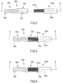
figures 2-4 schematically show three steps of connecting a portion of the assembly offigure 1 to a cable; -
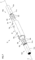
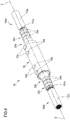
figures 5-8 schematically show four steps of connecting two cables by the assembly offigure 1 ; and -
figure 9 schematically shows an alternative embodiment of the present invention; -
figures 10 and11 schematically show another alternative embodiment of the present invention. - In
figures 1-8 , an embodiment of an assembly for electrical splice connection of two cables according to the present invention is indicated withnumeral reference 10. The two cables (more specifically an end portion of each of the two cables) are indicated withnumeral references figures 5-8 . - In the assembled configuration thereof,
assembly 10 extends coaxially to a longitudinal axis X-X. - In the specific exemplary embodiment herein shown, the structure of the two
cables assembly 10. - The structure of the
cables figures 2-4 , wherein justcable 100a (more specifically an end portion thereof) is shown. What stated with reference tocable 100a also applies tocable 100b. -
Cables metallic conductors protective sheath conductors - Between
conductors protective sheath conductors protective sheath -
Assembly 10 is configured to electrically connectcables conductors conductors protective sheath cable figure 2 . - As from
figure 1 ,assembly 10 comprises afirst compression connector 20a configured to be coupled tocable 100a and asecond compression connector 20b configured to be coupled tocable 100b. - Each
compression connector portion conductors cables - Each
compression connector spigot - Each crimping
portion respective compression connector spigot respective compression connector - When
compression connectors conductors compression connectors - Should instead
conductors connectors portion respective conductors connectors portion aluminium conductors connectors portion copper conductors - The material of the
spigots cable conductors - Should
conductors portion connector conductors 101a, 101 which it is intended to be connected with. The cross-sectional size of thespigots portion -
Connectors aluminium connector copper conductors - As detailed in
figure 2 , each crimpingportion blind hole conductors hole conductors conductors portion - Suitable fitters (not shown) configured to be housed within
holes small diameter conductors conductors portion - As shown in
figures 1 and5-8 , each crimpingportion hole conductors figures 2-4 . - Thanks to the provision of the crimping
portions conductors connectors - Each
spigot enlarged head - The cross-sectional size of
spigots conductors - In addition to having a given cross-sectional size,
spigots spigots - The provision of
connectors connectors cables -
Assembly 10 further comprises a firstopen shell 30 configured to accommodate thespigots figure 5 , and a secondopen shell 40 configured to be fastened to openshell 30 to wrap and hold in position thespigots figure 6 . - In the exemplary embodiment shown in the attached figures, both
open shells - Both
open shells portion 35 for accommodating theenlarged head spigots figure 1 . At the opposite axial portions with respect to the abovementioned recessedportion 35,serrations shells - In the embodiment shown in the attached drawings, the recessed
portion 35 lacks theserrations - Advantageously,
serrations spigots - Thanks to the elongated shape of both
open shells spigots - As the
spigots open shells - In the embodiment shown in
figures 1-8 ,open shell 40 comprises a plurality of throughholes respective locking screws figures 1 and6 ). - More specifically, at least one through
hole 45a is arranged at a first end portion of theopen shell 40. Said at least one throughhole 45a is located at a radially outer position with respect tospigot 25a (figure 6 ). Analogously, at least another throughhole 45b is arranged at the opposite end portion of the open shell 40 (figure 6 ). Said at least one throughhole 45b is located at a radially outer position with respect tospigot 25b. - As shown in
figures 1-8 , two throughholes 45a and two throughholes 45b are preferably provided, wherein throughholes 45a are arranged at the first end portion of theopen shell 40 and throughholes 45b are arranged at the opposite end portion of theopen shell 40. - In an embodiment not shown,
open shell 30 comprises the above throughholes open shells - In the embodiment shown in the
figures 1-8 , the mutual fastening ofopen shells figures 1 ,7 and8 ). In the present case, theouter sleeve 50 totally surroundsopen shells -
Sleeve 50 is preferably made of aluminium, more preferably tin plated in order to resist to corrosive environments. -
Sleeve 50 comprises a number of throughholes holes hole hole screws holes holes spigots position spigots - Through
holes - Preferably, locking
screws screws open shells outer sleeve 50, which would cause premature shearing of the bolts. - Since the locking screws 60a, 60b press onto the
spigots conductors spigots assembly 10. - Advantageously, locking
screws - In a different embodiment shown in
figure 9 , at least oneclamp open shells figure 9 , twoclamps clamp shells Clamps shells spigots - In a further embodiment shown in
figures 10 and11 , a snap coupling can be provided to fastenopen shells grooved tongue 81 can be provided at both the longitudinal sides of one ofshells 30, 40 (shell 40 infigures 10 and11 ) and aspline 82 can be provided at both the longitudinal sides of theother shell 30, 40 (shell 30 infigures 10 and11 ) to snap housing a respective one of the projectinggrooved tongues 81. - In the embodiments of
figures 9-11 , one or more through holes 45 can be provided inopen shell 30 and/or 40 for the insertion of locking screws, for example shear bolts, as auxiliary fastening members. - In another further embodiment, both the
open shells holes respective locking screws open shells locking screws - The
assembly 10 described above allows connecting different material andsize cable conductors cables - The
assembly 10 is capable of withstanding mechanical forces it is subjected to, including vibration. - As from
figures 2-3 , the electrical connection ofcables conductors blind hole connectors - Then, as from
figure 4 , the crimpingportions connectors conductors pre-connectorized cables -
Cables - If the
outer sleeve 50 is used, like in the embodiment offigures 1 ,5-8 , it is slid over one of thepre-connectorized cables outer sleeve 50 is preferably made slid over the upper cable end. Tapes or cable ties can be used to hold thesleeve 50 in position. -
Spigots open shell 30, with theenlarged heads portion 35 of theopen shell 30, as fromfigure 5 . -
Open shell 40 is then fastened to openshell 30 to wrapspigots 25afigure 6 .Shells - As from
figure 7 ,sleeve 50 is then positioned overshells holes holes - As from
figure 8 , lockingscrews holes spigots -
Clamps fit members sleeve 50 to fastenopen shells - Of course a man skilled in the art can make further modifications and changes to the invention described above in order to meet specific and contingent application requirements, these modifications and changes falling in any case within the scope of protection as defined by the following claims.
Claims (12)
- Assembly (10) for electrical splice connection of cables (100a, 100b), comprising:- a first connector (20a) comprising a first termination portion (25a) and a first crimping portion (22a) configured to be crimped onto a first cable conductor (101a);- a second connector (20b) comprising a second termination portion (25b) and a second crimping portion (22b) configured to be crimped onto a second cable conductor (101b);- a first open shell (30) provided with a seat for accommodating said first and second termination portions (25a, 25b);- a second open shell (40), wherein fastening elements are provided for fastening said second open shell (40) to said first open shell (30) so as to wrap and firmly hold in position said first and second termination portions (25a, 25b); wherein each of said first termination portion (25a) and second termination portion (25b) has a cylindrical shape;wherein each of said first termination portion (25a) and second termination portion (25b) comprises, at a respective free end portion thereof, an enlarged head (26a, 26b)
characterised in that each of said first open shell (30) and second open shell (40) comprises, at an axially central portion of a radially inner surface thereof, a respective recessed portion (35) for accommodating said enlarged heads (26a, 26b). - Assembly (10) according to claim 1, comprising an outer sleeve (50) configured to at least partly surround said first open shell (30) and said second open shell (40).
- Assembly (10) according to claim 2, wherein said outer sleeve (50) comprises at least two first through holes (55a, 55b), each of said at least two first through holes (55a, 55b) being intended to be aligned to a respective through hole of at least two second through holes (45a, 45b) formed in at least one of said first open shell (30) and said second open shell (40), the assembly further comprising at least one locking screw (60a, 60b).
- Assembly (10) according to claim 1, wherein said first open shell (30) and second open shell (40) are identical to each other.
- Assembly (10) according to claim 1, wherein each of said first and second cable conductors (101a, 101b) has a respective predetermined cross-sectional size and wherein each of said first crimping portion (22a) and second crimping portion (22b) has a cross-sectional size selected according to the cross-sectional size of a respective cable conductor of said first and second cable conductors (101a, 101b).
- Assembly (10) according to claim 1, wherein said first termination portion (25a) and second termination portion (25b) are identical.
- Assembly (10) according to claim 1, wherein at least one of said first and second open shells (30, 40) comprises, at a radially inner surface thereof, a serration (33a, 33b).
- Assembly (10) according to claim 1, wherein each of said first and second cable conductors (101a, 101b) has predetermined cross-sectional size and wherein each of said first termination portion (25a) and second termination portion (25b) has a cross-sectional size which is equal to, or greater than, the cross-sectional size of a respective cable conductors of said first and second cable conductors (101a, 101b).
- Assembly according to claim 1, wherein said first and second cable conductors (101a, 101b) are made of a respective predetermined material and wherein each of said first crimping portion (22a) and second crimping portion (22b) is made of the same material of a respective cable conductors of said first and second cable conductors (101a, 101b).
- Assembly (10) according to claim 3, wherein said locking screw (60a, 60b) is a shear bolt.
- Method for electrical splice connection of cables (100a, 100b), comprising:- providing a first connector (20a) comprising a first termination portion (25a) and a first crimping portion (22a);- providing a second connector (20b) comprising a second termination portion (25b) and a second crimping portion (22b);- crimping said first crimping portion (22a) onto a first cable conductor (101a);- crimping said second crimping portion (22b) onto a second cable conductor (101b);- accommodating said first and second termination portions (25a, 25b) on a seat provided on a first open shell (30);- fastening a second open shell (40) to said first open shell (30) so as to wrap and hold in position said first and second termination portions (25a, 25b);wherein each of said first termination portion (25a) and second termination portion (25b) has a cylindrical shape;
characterized in that accommodating the first and second termination portions (25a, 25b) on said seat provided on the first open shell (30) comprises accommodating an enlarged head (26a, 26b) provided at a free end portion of each of said first and second termination portions (25a, 25b) onto a recessed portion (35) at an axially central portion of a radially inner surface of said first open shell (30). - Method according to claim 11, wherein fastening said second open shell (40) to said first open shell (30) comprises:- positioning an outer sleeve (50) in a radially outer position with respect to the first open shell (30) and second open shell (40), said outer sleeve (50) comprising at least two first through holes (55a, 55b);- aligning each of said at least two first through holes (55a, 55b) to a respective through hole of at least two second through holes (45a, 45b) formed on at least one of said first open shell (30) and second open shell (40);- inserting a locking screw (60a, 60b) into each of said at least two first through holes (55a, 55b) and at least two second through holes (45a, 45b).
Applications Claiming Priority (1)
| Application Number | Priority Date | Filing Date | Title |
|---|---|---|---|
| PCT/EP2013/069186 WO2015036060A1 (en) | 2013-09-16 | 2013-09-16 | Assembly and method for electrical splice connection of cables |
Publications (2)
| Publication Number | Publication Date |
|---|---|
| EP3047539A1 EP3047539A1 (en) | 2016-07-27 |
| EP3047539B1 true EP3047539B1 (en) | 2019-06-12 |
Family
ID=49170723
Family Applications (1)
| Application Number | Title | Priority Date | Filing Date |
|---|---|---|---|
| EP13762511.7A Active EP3047539B1 (en) | 2013-09-16 | 2013-09-16 | Assembly and method for electrical splice connection of cables |
Country Status (5)
| Country | Link |
|---|---|
| US (1) | US9905942B2 (en) |
| EP (1) | EP3047539B1 (en) |
| AR (1) | AR097645A1 (en) |
| ES (1) | ES2744627T3 (en) |
| WO (1) | WO2015036060A1 (en) |
Families Citing this family (15)
| Publication number | Priority date | Publication date | Assignee | Title |
|---|---|---|---|---|
| US9819103B2 (en) * | 2012-03-16 | 2017-11-14 | Carre Technologies Inc. | Washable intelligent garment and components thereof |
| CN106129644A (en) * | 2016-07-15 | 2016-11-16 | 国家电网公司 | Graphite bonded earth electrode speed connects cartridge type and continues part and application thereof |
| EP3336971A1 (en) * | 2016-12-15 | 2018-06-20 | NKT HV Cables GmbH | A connector for jointing power cables |
| ES2758404R1 (en) * | 2017-10-03 | 2020-09-25 | Carbine Ventures Inc D/B/A Cable Tech Laboratories | Improved connectivity between conductive elements |
| DE102017221071B4 (en) * | 2017-11-24 | 2024-05-23 | Siemens Aktiengesellschaft | Electrical contact interface with a low and stable electrical contact resistance |
| CN108923370B (en) * | 2018-09-11 | 2024-09-17 | 沈阳兴华航空电器有限责任公司 | Connecting mechanism of segmented engine cable |
| DE102019112328A1 (en) * | 2019-05-10 | 2020-11-12 | Auto-Kabel Management Gmbh | Electrical connection console for vehicle power supply line |
| CN111129811A (en) * | 2019-12-23 | 2020-05-08 | 深圳供电局有限公司 | Grid line and cable terminal transition clip |
| CN111446557B (en) * | 2020-03-26 | 2021-12-10 | 阳光电源股份有限公司 | Wiring device of photovoltaic equipment |
| CN111786162B (en) * | 2020-05-22 | 2022-04-22 | 武汉船用机械有限责任公司 | Cable connecting device and spliced cable |
| CN113451822B (en) * | 2021-07-13 | 2022-09-16 | 四川华丰科技股份有限公司 | Integral high-current connector |
| EP4297209A1 (en) * | 2022-06-22 | 2023-12-27 | NKT HV Cables AB | Method for connecting conductors in a prefabricated cable accessory |
| CN116581685B (en) * | 2023-04-23 | 2024-02-02 | 广东鑫源恒业电力线路器材有限公司 | A method for optimizing the electrical performance of connecting pipes based on safety backup clamps |
| EP4597754A1 (en) * | 2024-01-30 | 2025-08-06 | NKT HV Cables AB | Connector for power cable |
| CN119994744B (en) * | 2025-04-17 | 2025-07-11 | 国网浙江省电力有限公司杭州市临平区供电公司 | Power cable protection device |
Citations (8)
| Publication number | Priority date | Publication date | Assignee | Title |
|---|---|---|---|---|
| GB913503A (en) * | 1960-01-14 | 1962-12-19 | Telefunken Gmbh | Improvements in or relating to electric cable connectors |
| USRE28877E (en) * | 1971-02-19 | 1976-06-22 | Electric cable connector | |
| FR2662846A1 (en) * | 1990-06-05 | 1991-12-06 | Materiel Electr Soc Ind | Connector for joining electrical conductors, especially for underground mains |
| GB2294597A (en) * | 1994-01-15 | 1996-05-01 | Sicame Electrical Dev Ltd | Electrical connector |
| EP1253692A1 (en) * | 2001-04-26 | 2002-10-30 | 3M Innovative Properties Company | Terminal of a medium voltage electrical cable |
| EP1988604A2 (en) * | 2007-05-01 | 2008-11-05 | TRI-STAR TECHNOLOGIES (a California Partnership) | Electrical contact assembly including a sleeve member |
| WO2008138299A1 (en) * | 2007-05-10 | 2008-11-20 | Cellpack Gmbh | Insulated cable connector |
| US20130056268A1 (en) * | 2011-09-07 | 2013-03-07 | Tyco Electronics Corporation | Electrical connector, an insert for an electrical connector and an electrical assembly |
Family Cites Families (9)
| Publication number | Priority date | Publication date | Assignee | Title |
|---|---|---|---|---|
| US3377422A (en) * | 1966-01-26 | 1968-04-09 | Amp Inc | Splice assembly to connect cable ends together |
| US3864013A (en) * | 1973-09-19 | 1975-02-04 | Thomas & Betts Corp | Pre-insulated connector for electrical conductors |
| US4269465A (en) * | 1979-12-26 | 1981-05-26 | Amp Incorporated | Splice connector for aluminum wire |
| US5041027A (en) * | 1989-07-21 | 1991-08-20 | Cooper Power Systems, Inc. | Cable splice |
| EP0563164B1 (en) | 1990-12-18 | 1996-02-07 | B & H (Nottingham) Limited | Electrical connector |
| US5821463A (en) * | 1996-06-14 | 1998-10-13 | The Whitaker Corporation | Mechanical connector splice for cable |
| KR101005127B1 (en) | 2004-03-01 | 2011-01-04 | 노비니움, 인크. | High voltage power cable connector |
| US8636524B2 (en) * | 2011-03-31 | 2014-01-28 | John Mezzalingua Associates, LLC | Split conductive mid-span ground clamp |
| US8826533B2 (en) * | 2011-06-24 | 2014-09-09 | Delphi Technologies, Inc. | Crimp connection to aluminum cable |
-
2013
- 2013-09-16 ES ES13762511T patent/ES2744627T3/en active Active
- 2013-09-16 EP EP13762511.7A patent/EP3047539B1/en active Active
- 2013-09-16 WO PCT/EP2013/069186 patent/WO2015036060A1/en not_active Ceased
- 2013-09-16 US US15/021,988 patent/US9905942B2/en active Active
-
2014
- 2014-09-12 AR ARP140103408A patent/AR097645A1/en active IP Right Grant
Patent Citations (8)
| Publication number | Priority date | Publication date | Assignee | Title |
|---|---|---|---|---|
| GB913503A (en) * | 1960-01-14 | 1962-12-19 | Telefunken Gmbh | Improvements in or relating to electric cable connectors |
| USRE28877E (en) * | 1971-02-19 | 1976-06-22 | Electric cable connector | |
| FR2662846A1 (en) * | 1990-06-05 | 1991-12-06 | Materiel Electr Soc Ind | Connector for joining electrical conductors, especially for underground mains |
| GB2294597A (en) * | 1994-01-15 | 1996-05-01 | Sicame Electrical Dev Ltd | Electrical connector |
| EP1253692A1 (en) * | 2001-04-26 | 2002-10-30 | 3M Innovative Properties Company | Terminal of a medium voltage electrical cable |
| EP1988604A2 (en) * | 2007-05-01 | 2008-11-05 | TRI-STAR TECHNOLOGIES (a California Partnership) | Electrical contact assembly including a sleeve member |
| WO2008138299A1 (en) * | 2007-05-10 | 2008-11-20 | Cellpack Gmbh | Insulated cable connector |
| US20130056268A1 (en) * | 2011-09-07 | 2013-03-07 | Tyco Electronics Corporation | Electrical connector, an insert for an electrical connector and an electrical assembly |
Also Published As
| Publication number | Publication date |
|---|---|
| US9905942B2 (en) | 2018-02-27 |
| AR097645A1 (en) | 2016-04-06 |
| ES2744627T3 (en) | 2020-02-25 |
| WO2015036060A1 (en) | 2015-03-19 |
| US20160226158A1 (en) | 2016-08-04 |
| EP3047539A1 (en) | 2016-07-27 |
Similar Documents
| Publication | Publication Date | Title |
|---|---|---|
| US9905942B2 (en) | Assemblies and methods for electrical splice connections of cables | |
| US8747170B2 (en) | Connector assemblies and systems and methods for forming disconnectable joint assemblies | |
| EP2115828B1 (en) | Knurled inner sleeve for a cable connector | |
| EP0750376A2 (en) | Electric cable termination gland | |
| CA2857012C (en) | Conductor connectors for power cables | |
| CN104396089B (en) | Electrical connection system | |
| CN104380537A (en) | Electric connection system | |
| WO2009097609A1 (en) | Segmented decompression resistant cable splice and method of installation | |
| US9147967B2 (en) | Electrical connectors and methods for using same | |
| US20200266554A1 (en) | Electrical connection bails and stirrup systems and methods including same | |
| US10326215B1 (en) | Pin aligning crimping fixture | |
| WO2016033608A1 (en) | System and method for forming end terminations of mineral insulated cable | |
| KR20250000500A (en) | Extension type adaptor to establish secure distance between bushings with transverse members formed at 90°and Method for intalling the same | |
| EP1844525B1 (en) | Electrical connector |
Legal Events
| Date | Code | Title | Description |
|---|---|---|---|
| PUAI | Public reference made under article 153(3) epc to a published international application that has entered the european phase |
Free format text: ORIGINAL CODE: 0009012 |
|
| 17P | Request for examination filed |
Effective date: 20160210 |
|
| AK | Designated contracting states |
Kind code of ref document: A1 Designated state(s): AL AT BE BG CH CY CZ DE DK EE ES FI FR GB GR HR HU IE IS IT LI LT LU LV MC MK MT NL NO PL PT RO RS SE SI SK SM TR |
|
| AX | Request for extension of the european patent |
Extension state: BA ME |
|
| DAX | Request for extension of the european patent (deleted) | ||
| STAA | Information on the status of an ep patent application or granted ep patent |
Free format text: STATUS: EXAMINATION IS IN PROGRESS |
|
| 17Q | First examination report despatched |
Effective date: 20170223 |
|
| RAP1 | Party data changed (applicant data changed or rights of an application transferred) |
Owner name: PRYSMIAN S.P.A. |
|
| REG | Reference to a national code |
Ref country code: DE Ref legal event code: R079 Ref document number: 602013056541 Country of ref document: DE Free format text: PREVIOUS MAIN CLASS: H01R0004200000 Ipc: H01R0011260000 |
|
| GRAP | Despatch of communication of intention to grant a patent |
Free format text: ORIGINAL CODE: EPIDOSNIGR1 |
|
| STAA | Information on the status of an ep patent application or granted ep patent |
Free format text: STATUS: GRANT OF PATENT IS INTENDED |
|
| RIC1 | Information provided on ipc code assigned before grant |
Ipc: H01R 4/26 20060101ALN20181205BHEP Ipc: H01R 11/26 20060101AFI20181205BHEP Ipc: H02G 15/18 20060101ALI20181205BHEP Ipc: H01R 4/36 20060101ALI20181205BHEP Ipc: H01R 4/20 20060101ALI20181205BHEP Ipc: H01R 43/26 20060101ALI20181205BHEP Ipc: H01R 11/01 20060101ALI20181205BHEP |
|
| INTG | Intention to grant announced |
Effective date: 20190108 |
|
| GRAS | Grant fee paid |
Free format text: ORIGINAL CODE: EPIDOSNIGR3 |
|
| GRAA | (expected) grant |
Free format text: ORIGINAL CODE: 0009210 |
|
| STAA | Information on the status of an ep patent application or granted ep patent |
Free format text: STATUS: THE PATENT HAS BEEN GRANTED |
|
| AK | Designated contracting states |
Kind code of ref document: B1 Designated state(s): AL AT BE BG CH CY CZ DE DK EE ES FI FR GB GR HR HU IE IS IT LI LT LU LV MC MK MT NL NO PL PT RO RS SE SI SK SM TR |
|
| REG | Reference to a national code |
Ref country code: GB Ref legal event code: FG4D |
|
| REG | Reference to a national code |
Ref country code: CH Ref legal event code: EP |
|
| REG | Reference to a national code |
Ref country code: AT Ref legal event code: REF Ref document number: 1143823 Country of ref document: AT Kind code of ref document: T Effective date: 20190615 |
|
| REG | Reference to a national code |
Ref country code: DE Ref legal event code: R096 Ref document number: 602013056541 Country of ref document: DE |
|
| REG | Reference to a national code |
Ref country code: IE Ref legal event code: FG4D |
|
| REG | Reference to a national code |
Ref country code: NL Ref legal event code: MP Effective date: 20190612 |
|
| REG | Reference to a national code |
Ref country code: LT Ref legal event code: MG4D |
|
| PG25 | Lapsed in a contracting state [announced via postgrant information from national office to epo] |
Ref country code: NO Free format text: LAPSE BECAUSE OF FAILURE TO SUBMIT A TRANSLATION OF THE DESCRIPTION OR TO PAY THE FEE WITHIN THE PRESCRIBED TIME-LIMIT Effective date: 20190912 Ref country code: AL Free format text: LAPSE BECAUSE OF FAILURE TO SUBMIT A TRANSLATION OF THE DESCRIPTION OR TO PAY THE FEE WITHIN THE PRESCRIBED TIME-LIMIT Effective date: 20190612 Ref country code: FI Free format text: LAPSE BECAUSE OF FAILURE TO SUBMIT A TRANSLATION OF THE DESCRIPTION OR TO PAY THE FEE WITHIN THE PRESCRIBED TIME-LIMIT Effective date: 20190612 Ref country code: SE Free format text: LAPSE BECAUSE OF FAILURE TO SUBMIT A TRANSLATION OF THE DESCRIPTION OR TO PAY THE FEE WITHIN THE PRESCRIBED TIME-LIMIT Effective date: 20190612 Ref country code: HR Free format text: LAPSE BECAUSE OF FAILURE TO SUBMIT A TRANSLATION OF THE DESCRIPTION OR TO PAY THE FEE WITHIN THE PRESCRIBED TIME-LIMIT Effective date: 20190612 Ref country code: LT Free format text: LAPSE BECAUSE OF FAILURE TO SUBMIT A TRANSLATION OF THE DESCRIPTION OR TO PAY THE FEE WITHIN THE PRESCRIBED TIME-LIMIT Effective date: 20190612 |
|
| PG25 | Lapsed in a contracting state [announced via postgrant information from national office to epo] |
Ref country code: BG Free format text: LAPSE BECAUSE OF FAILURE TO SUBMIT A TRANSLATION OF THE DESCRIPTION OR TO PAY THE FEE WITHIN THE PRESCRIBED TIME-LIMIT Effective date: 20190912 Ref country code: RS Free format text: LAPSE BECAUSE OF FAILURE TO SUBMIT A TRANSLATION OF THE DESCRIPTION OR TO PAY THE FEE WITHIN THE PRESCRIBED TIME-LIMIT Effective date: 20190612 Ref country code: LV Free format text: LAPSE BECAUSE OF FAILURE TO SUBMIT A TRANSLATION OF THE DESCRIPTION OR TO PAY THE FEE WITHIN THE PRESCRIBED TIME-LIMIT Effective date: 20190612 Ref country code: GR Free format text: LAPSE BECAUSE OF FAILURE TO SUBMIT A TRANSLATION OF THE DESCRIPTION OR TO PAY THE FEE WITHIN THE PRESCRIBED TIME-LIMIT Effective date: 20190913 |
|
| REG | Reference to a national code |
Ref country code: AT Ref legal event code: MK05 Ref document number: 1143823 Country of ref document: AT Kind code of ref document: T Effective date: 20190612 |
|
| PG25 | Lapsed in a contracting state [announced via postgrant information from national office to epo] |
Ref country code: RO Free format text: LAPSE BECAUSE OF FAILURE TO SUBMIT A TRANSLATION OF THE DESCRIPTION OR TO PAY THE FEE WITHIN THE PRESCRIBED TIME-LIMIT Effective date: 20190612 Ref country code: SK Free format text: LAPSE BECAUSE OF FAILURE TO SUBMIT A TRANSLATION OF THE DESCRIPTION OR TO PAY THE FEE WITHIN THE PRESCRIBED TIME-LIMIT Effective date: 20190612 Ref country code: CZ Free format text: LAPSE BECAUSE OF FAILURE TO SUBMIT A TRANSLATION OF THE DESCRIPTION OR TO PAY THE FEE WITHIN THE PRESCRIBED TIME-LIMIT Effective date: 20190612 Ref country code: EE Free format text: LAPSE BECAUSE OF FAILURE TO SUBMIT A TRANSLATION OF THE DESCRIPTION OR TO PAY THE FEE WITHIN THE PRESCRIBED TIME-LIMIT Effective date: 20190612 Ref country code: AT Free format text: LAPSE BECAUSE OF FAILURE TO SUBMIT A TRANSLATION OF THE DESCRIPTION OR TO PAY THE FEE WITHIN THE PRESCRIBED TIME-LIMIT Effective date: 20190612 Ref country code: NL Free format text: LAPSE BECAUSE OF FAILURE TO SUBMIT A TRANSLATION OF THE DESCRIPTION OR TO PAY THE FEE WITHIN THE PRESCRIBED TIME-LIMIT Effective date: 20190612 Ref country code: PT Free format text: LAPSE BECAUSE OF FAILURE TO SUBMIT A TRANSLATION OF THE DESCRIPTION OR TO PAY THE FEE WITHIN THE PRESCRIBED TIME-LIMIT Effective date: 20191014 |
|
| REG | Reference to a national code |
Ref country code: ES Ref legal event code: FG2A Ref document number: 2744627 Country of ref document: ES Kind code of ref document: T3 Effective date: 20200225 |
|
| PG25 | Lapsed in a contracting state [announced via postgrant information from national office to epo] |
Ref country code: SM Free format text: LAPSE BECAUSE OF FAILURE TO SUBMIT A TRANSLATION OF THE DESCRIPTION OR TO PAY THE FEE WITHIN THE PRESCRIBED TIME-LIMIT Effective date: 20190612 Ref country code: IS Free format text: LAPSE BECAUSE OF FAILURE TO SUBMIT A TRANSLATION OF THE DESCRIPTION OR TO PAY THE FEE WITHIN THE PRESCRIBED TIME-LIMIT Effective date: 20191012 |
|
| REG | Reference to a national code |
Ref country code: DE Ref legal event code: R097 Ref document number: 602013056541 Country of ref document: DE |
|
| PG25 | Lapsed in a contracting state [announced via postgrant information from national office to epo] |
Ref country code: TR Free format text: LAPSE BECAUSE OF FAILURE TO SUBMIT A TRANSLATION OF THE DESCRIPTION OR TO PAY THE FEE WITHIN THE PRESCRIBED TIME-LIMIT Effective date: 20190612 |
|
| PLBE | No opposition filed within time limit |
Free format text: ORIGINAL CODE: 0009261 |
|
| STAA | Information on the status of an ep patent application or granted ep patent |
Free format text: STATUS: NO OPPOSITION FILED WITHIN TIME LIMIT |
|
| PG25 | Lapsed in a contracting state [announced via postgrant information from national office to epo] |
Ref country code: PL Free format text: LAPSE BECAUSE OF FAILURE TO SUBMIT A TRANSLATION OF THE DESCRIPTION OR TO PAY THE FEE WITHIN THE PRESCRIBED TIME-LIMIT Effective date: 20190612 Ref country code: DK Free format text: LAPSE BECAUSE OF FAILURE TO SUBMIT A TRANSLATION OF THE DESCRIPTION OR TO PAY THE FEE WITHIN THE PRESCRIBED TIME-LIMIT Effective date: 20190612 |
|
| 26N | No opposition filed |
Effective date: 20200313 |
|
| PG25 | Lapsed in a contracting state [announced via postgrant information from national office to epo] |
Ref country code: SI Free format text: LAPSE BECAUSE OF FAILURE TO SUBMIT A TRANSLATION OF THE DESCRIPTION OR TO PAY THE FEE WITHIN THE PRESCRIBED TIME-LIMIT Effective date: 20190612 Ref country code: IS Free format text: LAPSE BECAUSE OF FAILURE TO SUBMIT A TRANSLATION OF THE DESCRIPTION OR TO PAY THE FEE WITHIN THE PRESCRIBED TIME-LIMIT Effective date: 20200224 Ref country code: MC Free format text: LAPSE BECAUSE OF FAILURE TO SUBMIT A TRANSLATION OF THE DESCRIPTION OR TO PAY THE FEE WITHIN THE PRESCRIBED TIME-LIMIT Effective date: 20190612 |
|
| REG | Reference to a national code |
Ref country code: CH Ref legal event code: PL |
|
| PG2D | Information on lapse in contracting state deleted |
Ref country code: IS |
|
| PG25 | Lapsed in a contracting state [announced via postgrant information from national office to epo] |
Ref country code: LU Free format text: LAPSE BECAUSE OF NON-PAYMENT OF DUE FEES Effective date: 20190916 Ref country code: LI Free format text: LAPSE BECAUSE OF NON-PAYMENT OF DUE FEES Effective date: 20190930 Ref country code: IE Free format text: LAPSE BECAUSE OF NON-PAYMENT OF DUE FEES Effective date: 20190916 Ref country code: CH Free format text: LAPSE BECAUSE OF NON-PAYMENT OF DUE FEES Effective date: 20190930 |
|
| REG | Reference to a national code |
Ref country code: BE Ref legal event code: MM Effective date: 20190930 |
|
| PG25 | Lapsed in a contracting state [announced via postgrant information from national office to epo] |
Ref country code: BE Free format text: LAPSE BECAUSE OF NON-PAYMENT OF DUE FEES Effective date: 20190930 |
|
| PG25 | Lapsed in a contracting state [announced via postgrant information from national office to epo] |
Ref country code: CY Free format text: LAPSE BECAUSE OF FAILURE TO SUBMIT A TRANSLATION OF THE DESCRIPTION OR TO PAY THE FEE WITHIN THE PRESCRIBED TIME-LIMIT Effective date: 20190612 |
|
| PG25 | Lapsed in a contracting state [announced via postgrant information from national office to epo] |
Ref country code: MT Free format text: LAPSE BECAUSE OF FAILURE TO SUBMIT A TRANSLATION OF THE DESCRIPTION OR TO PAY THE FEE WITHIN THE PRESCRIBED TIME-LIMIT Effective date: 20190612 Ref country code: HU Free format text: LAPSE BECAUSE OF FAILURE TO SUBMIT A TRANSLATION OF THE DESCRIPTION OR TO PAY THE FEE WITHIN THE PRESCRIBED TIME-LIMIT; INVALID AB INITIO Effective date: 20130916 |
|
| PG25 | Lapsed in a contracting state [announced via postgrant information from national office to epo] |
Ref country code: MK Free format text: LAPSE BECAUSE OF FAILURE TO SUBMIT A TRANSLATION OF THE DESCRIPTION OR TO PAY THE FEE WITHIN THE PRESCRIBED TIME-LIMIT Effective date: 20190612 |
|
| PGFP | Annual fee paid to national office [announced via postgrant information from national office to epo] |
Ref country code: DE Payment date: 20250929 Year of fee payment: 13 |
|
| PGFP | Annual fee paid to national office [announced via postgrant information from national office to epo] |
Ref country code: IT Payment date: 20250919 Year of fee payment: 13 |
|
| PGFP | Annual fee paid to national office [announced via postgrant information from national office to epo] |
Ref country code: GB Payment date: 20250929 Year of fee payment: 13 |
|
| PGFP | Annual fee paid to national office [announced via postgrant information from national office to epo] |
Ref country code: FR Payment date: 20250925 Year of fee payment: 13 |
|
| PGFP | Annual fee paid to national office [announced via postgrant information from national office to epo] |
Ref country code: ES Payment date: 20251001 Year of fee payment: 13 |