EP3047455B1 - Method and system for spine position detection - Google Patents
Method and system for spine position detection Download PDFInfo
- Publication number
- EP3047455B1 EP3047455B1 EP14787274.1A EP14787274A EP3047455B1 EP 3047455 B1 EP3047455 B1 EP 3047455B1 EP 14787274 A EP14787274 A EP 14787274A EP 3047455 B1 EP3047455 B1 EP 3047455B1
- Authority
- EP
- European Patent Office
- Prior art keywords
- vertebra body
- current
- image
- geometrical configuration
- component
- Prior art date
- Legal status (The legal status is an assumption and is not a legal conclusion. Google has not performed a legal analysis and makes no representation as to the accuracy of the status listed.)
- Active
Links
Images





Classifications
-
- A—HUMAN NECESSITIES
- A61—MEDICAL OR VETERINARY SCIENCE; HYGIENE
- A61B—DIAGNOSIS; SURGERY; IDENTIFICATION
- A61B6/00—Apparatus or devices for radiation diagnosis; Apparatus or devices for radiation diagnosis combined with radiation therapy equipment
- A61B6/50—Apparatus or devices for radiation diagnosis; Apparatus or devices for radiation diagnosis combined with radiation therapy equipment specially adapted for specific body parts; specially adapted for specific clinical applications
- A61B6/505—Apparatus or devices for radiation diagnosis; Apparatus or devices for radiation diagnosis combined with radiation therapy equipment specially adapted for specific body parts; specially adapted for specific clinical applications for diagnosis of bone
-
- A—HUMAN NECESSITIES
- A61—MEDICAL OR VETERINARY SCIENCE; HYGIENE
- A61B—DIAGNOSIS; SURGERY; IDENTIFICATION
- A61B6/00—Apparatus or devices for radiation diagnosis; Apparatus or devices for radiation diagnosis combined with radiation therapy equipment
- A61B6/02—Arrangements for diagnosis sequentially in different planes; Stereoscopic radiation diagnosis
- A61B6/03—Computed tomography [CT]
- A61B6/032—Transmission computed tomography [CT]
-
- A—HUMAN NECESSITIES
- A61—MEDICAL OR VETERINARY SCIENCE; HYGIENE
- A61B—DIAGNOSIS; SURGERY; IDENTIFICATION
- A61B6/00—Apparatus or devices for radiation diagnosis; Apparatus or devices for radiation diagnosis combined with radiation therapy equipment
- A61B6/52—Devices using data or image processing specially adapted for radiation diagnosis
- A61B6/5211—Devices using data or image processing specially adapted for radiation diagnosis involving processing of medical diagnostic data
-
- G—PHYSICS
- G06—COMPUTING OR CALCULATING; COUNTING
- G06T—IMAGE DATA PROCESSING OR GENERATION, IN GENERAL
- G06T7/00—Image analysis
- G06T7/10—Segmentation; Edge detection
-
- G—PHYSICS
- G06—COMPUTING OR CALCULATING; COUNTING
- G06T—IMAGE DATA PROCESSING OR GENERATION, IN GENERAL
- G06T7/00—Image analysis
- G06T7/10—Segmentation; Edge detection
- G06T7/12—Edge-based segmentation
-
- G—PHYSICS
- G06—COMPUTING OR CALCULATING; COUNTING
- G06T—IMAGE DATA PROCESSING OR GENERATION, IN GENERAL
- G06T7/00—Image analysis
- G06T7/10—Segmentation; Edge detection
- G06T7/149—Segmentation; Edge detection involving deformable models, e.g. active contour models
-
- G—PHYSICS
- G06—COMPUTING OR CALCULATING; COUNTING
- G06T—IMAGE DATA PROCESSING OR GENERATION, IN GENERAL
- G06T7/00—Image analysis
- G06T7/70—Determining position or orientation of objects or cameras
-
- G—PHYSICS
- G16—INFORMATION AND COMMUNICATION TECHNOLOGY [ICT] SPECIALLY ADAPTED FOR SPECIFIC APPLICATION FIELDS
- G16H—HEALTHCARE INFORMATICS, i.e. INFORMATION AND COMMUNICATION TECHNOLOGY [ICT] SPECIALLY ADAPTED FOR THE HANDLING OR PROCESSING OF MEDICAL OR HEALTHCARE DATA
- G16H50/00—ICT specially adapted for medical diagnosis, medical simulation or medical data mining; ICT specially adapted for detecting, monitoring or modelling epidemics or pandemics
- G16H50/20—ICT specially adapted for medical diagnosis, medical simulation or medical data mining; ICT specially adapted for detecting, monitoring or modelling epidemics or pandemics for computer-aided diagnosis, e.g. based on medical expert systems
-
- A—HUMAN NECESSITIES
- A61—MEDICAL OR VETERINARY SCIENCE; HYGIENE
- A61B—DIAGNOSIS; SURGERY; IDENTIFICATION
- A61B6/00—Apparatus or devices for radiation diagnosis; Apparatus or devices for radiation diagnosis combined with radiation therapy equipment
- A61B6/52—Devices using data or image processing specially adapted for radiation diagnosis
- A61B6/5211—Devices using data or image processing specially adapted for radiation diagnosis involving processing of medical diagnostic data
- A61B6/5217—Devices using data or image processing specially adapted for radiation diagnosis involving processing of medical diagnostic data extracting a diagnostic or physiological parameter from medical diagnostic data
-
- G—PHYSICS
- G06—COMPUTING OR CALCULATING; COUNTING
- G06T—IMAGE DATA PROCESSING OR GENERATION, IN GENERAL
- G06T2207/00—Indexing scheme for image analysis or image enhancement
- G06T2207/10—Image acquisition modality
- G06T2207/10072—Tomographic images
- G06T2207/10081—Computed x-ray tomography [CT]
-
- G—PHYSICS
- G06—COMPUTING OR CALCULATING; COUNTING
- G06T—IMAGE DATA PROCESSING OR GENERATION, IN GENERAL
- G06T2207/00—Indexing scheme for image analysis or image enhancement
- G06T2207/30—Subject of image; Context of image processing
- G06T2207/30004—Biomedical image processing
- G06T2207/30008—Bone
- G06T2207/30012—Spine; Backbone
Definitions
- the present disclosure relates to digital image processing, and more particularly to a system and method for spine position detection.
- the digital imaging technology has experienced significant growth in recent years. Examples of such growth include the development of using computers for assisting analysis of spines in radiography. In a clinical examination, transverse image is usually used for detecting an abnormality of an inter-vertebral disk. Position and orientation of intervertebral disc are important anatomies for the diagnosis.
- WO 2011/021181 A1 discloses a method for modeling a spine, comprising providing at least one image of the spine, extracting a plurality of anatomical elements of the spine from the at least one image, and constructing a model representing the anatomy of the spine using the anatomical elements.
- a method for spine position detection comprising: obtaining 2D geometrical configuration of a current vertebra body selected from a plurality of vertebra bodies visible in an image on a sagittal plane defined by a horizontal component of an initial point, the initial point having horizontal, vertical and axial components in a three-dimensional Cartesian coordinate system, a geometrical template being applied to the current vertebra body and the 2D geometrical configuration of the current vertebra body being adjusted by a predetermined correlation evaluation; searching adjacent edge points of next vertebra body corresponding to a number of edge points of the current vertebra body by identifying the gradient values along the direction substantially perpendicular to the edge of the current vertebra body based on the adjusted 2D geometrical configuration of the current vertebra body; calculating the height of an intervertebral disc located between the current vertebra body and the next vertebra body based on an average of the distances between the edge points of the current vertebra body and the corresponding adjacent edge points of the next vertebra body; determining 2D geometrical configuration of a current vertebra body selected from
- the geometrical template is a rectangular template with 2D parameter values on the sagittal plane.
- the predetermined correlation evaluation comprises a particle filtering.
- a system for spine position detection comprising: a program storage device readable by machine, tangibly embodying a program of instructions executable by the machine to perform above methods.
- FIG. 1 shows standard anatomical position defined for human anatomy.
- the last vertebral body is selected by a user (e.g. a physical clinician) as the initial vertebra body.
- a point P indicated on center of the last vertebral body is selected as the initial point with three coordinate components (horizontal component P x , vertical component P y , axial component P z ) in the three-dimensional (3D) Cartesian coordinate system.
- the coordinate value of the midpoint placed on a line along horizontal direction in an image on a transverse plane is specified as the horizontal component P x .
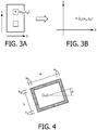
- the coordinate values of the center of the last vertebral body are specified as vertical component P y and axial component P z , as shown in FIG. 3A .
- the sagittal plane is used commonly.
- the vertical component P y and the axial component P z can be converted to x z and y z respectively to define a point Q 0 ( x z , y z ) in a two dimensional (2D) coordinate system such as a Cartesian coordinate system as shown in FIG.3B .
- 2D two dimensional
- the horizontal direction and the vertical direction on the sagittal plane can be referred as the converted horizontal direction and the converted vertical direction.
- a geometrical template is applied to the spine. Since the shape of the vertebral body or the intervertebral disc is similar to a rectangular band, in one embodiment, a rectangular template with 2D parameter values is provided as one example of the geometrical template.
- the 2D geometrical configuration of a vertebra body i.e. 2D geometrical parameters of the rectangular template
- the 2D geometrical configuration of a vertebra body comprises: center ( x , y ), width w, height h and orientation ⁇ of the rectangular template wherein ⁇ is the angle between the upper edge or lower edge of the rectangular template and the horizontal direction.
- Q 0 ( x z , y z ) is specified as the center ( x , y ).
- the width w and the height h are specified as predetermined values w z and h z of normal human.
- the orientation ⁇ is specified as ⁇ z . Since the last vertebral body is initialized as the current vertebral body, the orientation ⁇ z is set as zero.
- the 2D geometrical configuration of the vertebra body may further comprise interior width w b and interior height h b . Normally, w b and h b are constant values for a person.
- the 2D geometrical information i.e. the 2D geometrical parameters of the rectangular template
- the 2D geometrical information of the intervertebral disc can be derived from the 2D geometrical configuration of the current vertebral body and the 2D geometrical configuration of the next adjacent vertebral body. The derivation will be described in details later.
- the 2D geometrical configuration ( Q 0 ( x z , y z ), w z , h z , ⁇ z ) of the current vertebral body.
- the 2D geometrical configuration is further optimized through a predetermined correlation evaluation.
- the 2D geometrical configuration shall be adjusted so that the rectangular template with the adjusted 2D geometrical parameters would be well matched with the image of the current vertebral body.
- the interior area of the vertebra body has a homogeneous intensity distribution; while the intensity distribution of the border region defined by w b and h b is clearly demarcated; and the strong gradient values only appear on the border of the rectangular template for the vertebra body.
- the correlation between the rectangular template and the image of the current vertebral body can be evaluated by the intensity correlation and/or the gradient correlation.
- the image appearance value of s is defined as p s
- X i e ⁇ I s ⁇ ⁇ i 2 2 ⁇ i 2
- I(s) is each pixel's intensity value.
- X i ) is defined as p I I
- X i e ⁇ I c I i
- c I i is the cross-correlation between the image appearance values p(s
- X i ) can be defined as p G I
- X i e ⁇ G c G i where c G i is the cross-correlation between the gradient image values of the observed image in the rectangular template area and a positive template wherein the interior area of the template is set value 0 and the border region is set value 1.
- the 2D geometrical configuration obtained in the initialization can be adjusted or updated by the 2D geometrical parameters of the optimized rectangular template so that the rectangular template for the current vertebral body can match the image of the current vertebral body as closely as possible.
- a particle filtering algorithm is used as one example of the predetermined correlation evaluation.
- the number of the particles is not more than 100 and the range of 2D parameter values for a rectangular template is defined as follows by considering the time consuming during the operation of the particle filtering algorithm: x ⁇ Q 0 . x ⁇ 10 mm , Q 0 . x + 10 mm y ⁇ Q 0 . y ⁇ 5 mm , Q 0 . y + 5 mm w h ⁇ 1 1.5 wherein x is the parameter value along the converted horizontal direction on the sagittal plane, Q 0 .x (i.e. x z in FIG.
- the particle which is the most correlated to the image of the current vertebra body is selected as the 2D geometrical parameters of the rectangular template. Based on the rectangular template updated with the selected particle, the 2D geometrical configuration of the next vertebra body can be determined.
- the 2D geometrical configuration ( Q 0 ( x z , y z ), w z , h z , ⁇ z ) of the rectangular template of the last vertebra body (called as initial vertebra body V 0 herein) is adjusted to (Q 0 ' ( x z ' , y z ' ), w z ' , h z ' , ⁇ z ') with the selected particle.
- the rectangular template with the adjusted 2D geometrical parameters is also applied to the next vertebra body V 1 .
- the next vertebra body V 1 is positioned along upward direction and adjacent to the last vertebra body V 0 .
- h d is the height of the intervertebral disc located between the last vertebra body V 0 and the next vertebra body V 1 .
- h d can be calculated as the average distance between the upper edge points of the last vertebra body V 0 and the corresponding bottom edge points of the next vertebra body V 1 .
- FIG. 5B based on the adjusted 2D geometrical configuration of the last vertebra body V 0 , e.g. selecting a plurality of points h 01 , h 02 ...
- the corresponding bottom edge points h 11 , h 12 ...h 1n of the next vertebra body V 1 can be searched by identifying the gradient values along the direction substantially perpendicular to the upper edge of the last vertebra body V 0 .
- the gradient value of the vertebra body especially the border of the vertebra body, is quite different from the gradient value of the intervertebral disc.
- the average distance h d is obtained as the average of the distance between h 01 and h 11 , the distance between h 02 and h 12 ...
- the line between upper edge point (e.g. h 01 ) of the last vertebra body V 0 and the corresponding bottom edge point ( h 11 ) of next vertebra body V 1 has an angle ⁇ h with respect to the converted vertical direction.
- the angle ⁇ h equals to the adjusted orientation ⁇ z ' of the last vertebra body V 0 .
- the next vertebra body V 1 can be considered as the current vertebra body.
- the width w 1 , the height h 1 and the orientation ⁇ 1 of the rectangular template for the current vertebra body V 1 can be set with the updated 2D geometrical configuration of the last vertebra body V 0 , i.e. w z ', h z ' , ⁇ z '.
- the 2D geometrical configuration is optimized through the predetermined correlation evaluation as well.
- the 2D geometrical parameters of the rectangular template is adjusted to cause the adjusted 2D geometrical configuration is most matchable with the image of the current vertebral body V 1 .
- the 2D geometrical configuration of the next current vertebra V 2 can be determined in a similar way as mentioned above.
- FIG. 6 illustrates a block/flow diagram for a detection method mentioned above in accordance with one embodiment of the present disclosure.
- an image of a part of the spine is specified on the sagittal plane which is defined by the horizontal component P x of the initial point P( P x , P y , P z ).
- the last vertebra body V 0 of the spine, as the current vertebra body, is selected by the user as the initial vertebra body (as shown in FIG. 2 ).
- the initial point P is specified as the center of the initial vertebra body.
- a rectangular template as a geometrical template is applied to the image of each of the vertebra bodies which are specified on the sagittal plane .
- the 2D geometrical configuration ( Q 0 ( x z , y z ), w z , h z , ⁇ z ) of the last vertebra body V 0 is obtained by identifying the geometrical parameters of the rectangular template.
- the coordinate values of the center Q 0 ( x z ,y z ) can be specified on the sagittal plane; width w z , height h z , and orientation ⁇ z are provided with the predetermined values.
- the obtained 2D geometrical configuration of the last vertebra body V 0 is adjusted to ( Q 0 ' ( x z ' , y z ' ), w z ' , h z ' , ⁇ z ' ) by a predetermined correlation evaluation.
- the predetermined correlation evaluation is the particle filtering algorithm.
- the adjacent edge points (i.e. the bottom edge points) of the next vertebra body V 1 can be searched from the corresponding points (i.e. upper edge points) of the last vertebra body V 0 , as described in one embodiment shown in FIG. 5B .
- the height h d of the intervertebral disc located between the last vertebra body V 0 and the next vertebra body V 1 can be calculated based on an average of the distances between the searched adjacent edge points of the next vertebra body V 1 and the corresponding edge points of the last vertebra body V 0 .
- 2D geometrical configuration of the next vertebra body V 1 can be determined based on the height h d of the intervertebral disc and the adjusted 2D geometrical configuration ( Q 0 ' ( x z ' , y z ' ), w z ' , h z ' , ⁇ z ' ) of the last vertebra body V 0 as shown in FIG. 5A .
- the obtained 2D geometrical configuration is adjusted to ( Q 1 ' ( x 1 ' , y 1 ' ), w 1 ', h 1 ', ⁇ 1 ' ) by a predetermined correlation evaluation such as particle filtering algorithm.
- the adjusted 2D geometrical configuration of the next vertebra body V 1 as the current vertebra body, can be served to determine the 2D geometrical configuration of the subsequent vertebra body V 2 positioned along the upward direction.
- the steps in blocks 40-70 are repeated.
- the 2D geometrical configuration of each vertebra body can be detected in sequence by this way.
- a method according to an embodiment of the present disclosure performs a detection of 2D geometrical information of the intervertebral disc.
- the horizontal component x d of the center of the intervertebral disc Disk 1 located between the last vertebra body V 0 and the next vertebra body V 1 can be calculated as an average of x z ' and x 1 '
- the vertical component y d of the center of the intervertebral disc Disk 1 can be calculated as an average of y z ' and y 1 ' (as shown in FIG. 5A ).
- FIG. 5A In another embodiment as shown in FIG.
- the horizontal component x d of the center of the intervertebral disc Disk 1 can be calculated as an average of c 0 and c 1 wherein c 0 is the midpoint of the upper edge of the last vertebra body V 0 with the adjusted 2D geometrical configuration and c 1 is the midpoint of the bottom edge of the next vertebra body V 1 with the adjusted 2D geometrical configuration.
- the orientation ⁇ d of the intervertebral disc Disk 1 can be calculated as an average of ⁇ z ' and ⁇ 1 '.
- the center ( x d , y d ) and the orientation ⁇ d of the intervertebral disc Disk 1 can be derived from the adjusted 2D geometrical configuration of the current vertebra body V 0 and the adjusted 2D geometrical configuration of the next vertebra body V 1 .
- the height h d of the intervertebral disc located between the last vertebra body V 0 and the next vertebra body V 1 can be updated based on the adjusted 2D geometrical configuration ( Q 0 ' ( x z ' , y z ' ), w z ' , h z ' , ⁇ z ' ) of the last vertebra body V 0 and adjusted 2D geometrical configuration ( Q 1 ' ( x 1 ', y 1 ' ), w 1 ', h 1 ', ⁇ 1 ' ) of the next vertebra body V 1 .
- the average distance h d is updated with the distance h d ' between c 0 and c 2 .
- Point c 2 is one of the bottom edge points of the next vertebra body V 1 with the adjusted 2D geometrical configuration.
- the line between c 0 and c 2 is substantially perpendicular to the bottom edge of the next vertebra body V 1 .
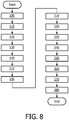
- FIG. 8 illustrates a block/flow diagram for a detection method in accordance with one embodiment of the present disclosure wherein the 3D components of the initial point is determined automatically.
- any one of vertebra bodies visible in an image on a sagittal plane is selected as an initial vertebra body.
- current vertebra body V 0 ' is identified as the initial vertebra body.
- 3D components of an initial point R positioned in the center of the current vertebra body V 0 ' can be obtained by the following steps.
- a number of transverse slices of the current vertebra body V 0 ' are selected.
- a pair of left edge and right edge ( t 1 , t 2 ) of an image along the horizontal direction for each of the selected transverse slices can be searched by the image regional growth as shown in FIG. 9B .
- a first reference point m 1 is positioned in the middle of the left edge and right edge ( t 1 , t 2 ) of the image along the horizontal direction.
- the coordinate value of the first reference point m 1 can be derived from an average of the coordinate values of the left edge t 1 and right edge t 2 .
- a first center point X as the horizontal component R x of the initial point R can be calculated as an average of the coordinate value of the first reference point m 1 of each transverse slice.
- a sagittal plane is defined by the horizontal component R x .
- a pair of maximum value and minimum value ( y max , y min ) for an image of the current vertebra body V 0 ' along a converted horizontal direction on the sagittal plane can be searched by the image regional growth.
- a second center point Y as vertical component R y of the initial point R can be calculated as an average of the maximum value y max and minimum value y min .
- an image of the intervertebral disc on a first transverse plane is quite different from an image of the vertebra body on a second transverse plane.
- the size of the image of the intervertebral disc identified on the first transverse plane is larger than the image of the vertebra body identified on the second transverse plane.
- the upper side and the lower side of the current vertebra body V 0 ' can be searched by identifying the two intervertebral discs adjacent to the current vertebra body.
- a third center point Z along a converted vertical direction on the sagittal plane as axial component R z of the initial point R can be determined based on the positions of the two intervertebral discs.
- the axial component R z is an average of axial values of the upper side and the lower side of the current vertebra body V 0 '.
- the axial component R z can be further adjusted by the following step:
- an image of the current vertebra body V 0 ' is identified on a coronal plane by the image regional growth wherein the coronal plane is defined by the second center point Y.
- a second reference point n is defined by the first center point X and the third center point Z on the coronal plane.
- the left edge L and right edge R of the image on the coronal plane can be searched from the second reference point n and along a horizontal direction of the coronal plane (as shown in FIG. 9C ).
- the half distance between the left edge L and right edge R can be used as the radius of a circle C wherein the circle C is placed on a third transverse plane defined by the third center point Z.
- the center of the circle C is defined by the first center point X and the second center point Y.
- the first center point X can be updated with the midpoint X' located on a line along the horizontal direction between the left edge L and right edge R of the image on the coronal plane.
- the center of the circle C' is defined by the first center point X' and the second center point Y.
- a group of mark points ( d 1 , d 2 ...d n ) are selected wherein the mark points ( d 1 , d 2 ...d n ) are positioned on a diameter D1 of the circle C as shown in FIG. 9D .
- Each mark point (e.g. d 1 ) is served to define a coronal slice (e.g. s 1 ).
- a number of coronal slices ( s 1 , s 2 , ...s n ) are defined by a group of mark points ( d 1 , d 2 ...d n ) correspondingly.
- an axial center point a 1 is calculated based on a pair of upper side and lower side of the current vertebra body V 0 '.
- the axial center point a 1 is calculated as an average of the coordinate values of the upper side and lower side of the current vertebra body V 0 '.
- a group of axial center points ( a 1 , a 2 ... a n ) can be obtained from the corresponding coronal slices ( s 1 , s 2 , ... s n ).
- a fourth center point can be derived from the group of axial center points ( a 1 , a 2 ... a n ).
- the fourth center point Z' is calculated based on an average of the coordinate values of the group of axial center points ( a 1 , a 2 ... a n ).
- the axial component R z of the initial point R is adjusted with the fourth center point Z'.
- a number of groups of mark points are selected wherein each group of the mark points are positioned on a diameter of the circle C.
- a group of the mark points ( d 11 , d 12 ...d 1n ) are placed on the diameter D1 of the circle C
- another group of the mark points ( d 21 , d 22 ...d 2n ) are placed on the diameter D2 of the circle C.
- 2n coronal slices can be defined by the two groups of mark points correspondingly.
- the fourth center point Z" is calculated based on an average of the coordinate values of the two group of axial center points, and the axial component R z of the initial point R is adjusted with the fourth center point Z".
- the number of groups of mark points can be selected based on the accuracy of the axial component R z .
- the 2D geometrical configuration of the current vertebra body V 0 ' is obtained by identifying the geometrical parameters of the rectangular template.
- the 2D geometrical configuration of each vertebra body in the upward direction of the current vertebra body V 0 ' can be detected in sequence.
- This sequential procedure i.e. steps in blocks 20-70
- the last vertebral body can be identified since the horizontal component h s of an image of sacrum on a transverse plane is quite different from the horizontal component h l of an image of the last vertebra body on a transverse plane as shown in FIG. 10 .
- the step for identifying the sacrum is performed first. If a detected subject is a vertebra body rather than the sacrum, the sequential procedure (i.e. steps in blocks 20-70) is carried out to obtain the 2D geometrical configuration of the vertebra body.
- the positions, heights and orientations of intervertebral discs can be determined according to one example of the method as described in conjunction with FIG. 7 . Then the transverse images of the intervertebral discs can be formed to serve for diagnosis.
- the approach according to the present invention presents a good performance on the accuracy and the speed of the imaging due to a reduction of manual operation in the examination.
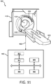
- FIG. 11 An exemplary CT imaging system 400 is shown in FIG. 11 .
- a general-purpose computing system serves as an operator controller 480.
- the controller 480 includes one or more processors 482 that execute one or more computer readable instructions (i.e. the elements in above blocks implemented in the form of the software) stored or encoded in computer readable storage medium 484 local or remote to the computing system.
- Software resident on the controller allows the operator to control operation of the system initiating scanning, etc.
- the controller also includes an output device 486 such as display and an input device 488 such as a keyboard, mouse, touch screen, etc.
- this CT imaging system 400 includes a gantry 410 and a support 420.
- a patient or other subject to be imaged (not shown in FIG. 11 ) lies down on the support 420 and is moved to be disposed within an aperture 430 in the gantry 410.
- a CT imaging acquisition system comprises an x-ray source 440 and an x-ray detector 450. Once the patient is in position, the x-ray source 440 and the x-ray detector 450 rotate together around the aperture 430 to record CT imaging data.
- the CT imaging data is supplied to the operator controller 480 through a communication link 460 for the spine position detection.
Landscapes
- Engineering & Computer Science (AREA)
- Health & Medical Sciences (AREA)
- Life Sciences & Earth Sciences (AREA)
- Medical Informatics (AREA)
- Physics & Mathematics (AREA)
- Theoretical Computer Science (AREA)
- Computer Vision & Pattern Recognition (AREA)
- Biomedical Technology (AREA)
- General Physics & Mathematics (AREA)
- Public Health (AREA)
- General Health & Medical Sciences (AREA)
- Pathology (AREA)
- Nuclear Medicine, Radiotherapy & Molecular Imaging (AREA)
- Radiology & Medical Imaging (AREA)
- Veterinary Medicine (AREA)
- Biophysics (AREA)
- High Energy & Nuclear Physics (AREA)
- Optics & Photonics (AREA)
- Heart & Thoracic Surgery (AREA)
- Molecular Biology (AREA)
- Surgery (AREA)
- Animal Behavior & Ethology (AREA)
- Pulmonology (AREA)
- Oral & Maxillofacial Surgery (AREA)
- Dentistry (AREA)
- Orthopedic Medicine & Surgery (AREA)
- Software Systems (AREA)
- Data Mining & Analysis (AREA)
- Databases & Information Systems (AREA)
- Epidemiology (AREA)
- Primary Health Care (AREA)
- Apparatus For Radiation Diagnosis (AREA)
- Magnetic Resonance Imaging Apparatus (AREA)
- Quality & Reliability (AREA)
Description
- The present disclosure relates to digital image processing, and more particularly to a system and method for spine position detection.
- The digital imaging technology has experienced significant growth in recent years. Examples of such growth include the development of using computers for assisting analysis of spines in radiography. In a clinical examination, transverse image is usually used for detecting an abnormality of an inter-vertebral disk. Position and orientation of intervertebral disc are important anatomies for the diagnosis.
- Currently, measurements in the clinical examination need human interaction, one example as a CT scanner with a gantry which cannot be rotatable. Usually, positions and orientations of intervertebral discs are placed manually on the spine for such CT scanner. Manual measurement is not only time-consuming, but also subject to errors depending on the person's skill, experience and other human factors.
-
WO 2011/021181 A1 discloses a method for modeling a spine, comprising providing at least one image of the spine, extracting a plurality of anatomical elements of the spine from the at least one image, and constructing a model representing the anatomy of the spine using the anatomical elements. - Therefore, a need exists for a method and system for spine position detection that require less human interaction.
- According to an embodiment of the present disclosure, a method for spine position detection is provided, comprising: obtaining 2D geometrical configuration of a current vertebra body selected from a plurality of vertebra bodies visible in an image on a sagittal plane defined by a horizontal component of an initial point, the initial point having horizontal, vertical and axial components in a three-dimensional Cartesian coordinate system, a geometrical template being applied to the current vertebra body and the 2D geometrical configuration of the current vertebra body being adjusted by a predetermined correlation evaluation; searching adjacent edge points of next vertebra body corresponding to a number of edge points of the current vertebra body by identifying the gradient values along the direction substantially perpendicular to the edge of the current vertebra body based on the adjusted 2D geometrical configuration of the current vertebra body; calculating the height of an intervertebral disc located between the current vertebra body and the next vertebra body based on an average of the distances between the edge points of the current vertebra body and the corresponding adjacent edge points of the next vertebra body; determining 2D geometrical configuration of the next vertebra body based on the height of the intervertebral disc and the adjusted 2D geometrical configuration of the current vertebra body.
- In one aspect, the geometrical template is a rectangular template with 2D parameter values on the sagittal plane.
- In another aspect, the predetermined correlation evaluation comprises a particle filtering.
- According to another embodiment of the present disclosure, a system for spine position detection, comprising: a program storage device readable by machine, tangibly embodying a program of instructions executable by the machine to perform above methods.
- The results of experiments show that, according to techniques described herein, accuracy and speed of the measurement are improved since human interaction during the spine position detection is much reduced.
- Various aspects and features of the disclosure are described in further detail below. And other objects and advantages of the present invention will become more apparent and will be easily understood with reference to the description made in combination with the accompanying drawings.
- The present disclosure will be described and explained hereinafter in more detail in combination with solutions and with reference to the drawings, wherein:
-
FIG. 1 is a diagram of standard anatomical position defined for human anatomy; -
FIG. 2 is a sagittal view of visible vertebra bodies according to one embodiment of the present disclosure; -
FIG. 3A is an illustration of vertebra bodies on a sagittal plane; -
FIG. 3B is an illustration of the center of last vertebra body in a Cartesian coordinate system; -
FIG. 4 is a sagittal view of the last vertebral body which is approximated by a rectangle template; -
FIG. 5A is an illustration of geometrical parameters of the visible vertebra bodies; -
FIG. 5B is an illustration of the height of the intervertebral disc located between the last vertebra body V0 and the next vertebra body V1 -
FIG. 5C is an illustration of the average height of the intervertebral disc; -
FIG. 6 is a block/flow diagram showing a detection method according to one embodiment of the present disclosure; -
FIG. 7 is a block/flow diagram showing a method for detecting the intervertebral discs according to one embodiment of the present disclosure; -
FIG. 8 is a block/flow diagram showing a detection method according to another embodiment of the present disclosure; -
FIG. 9A is a sagittal view of current vertebra body according to another embodiment of the present disclosure; -
FIG. 9B is a transverse view of the current vertebra body; -
FIG. 9C is a coronal view of the current vertebra body; -
FIG. 9D is an illustration of the mark points according to one embodiment of the present disclosure; -
FIG. 9E is an illustration of the mark points according to another embodiment of the present disclosure; -
FIG. 10 is an illustration of the last vertebra body and the sacrum; -
FIG. 11 is an illustration of a CT imaging system according to one embodiment of the present disclosure. - The same reference signs in the figures indicate similar or corresponding feature and/or functionality.
- The present invention will be described with respect to particular solutions and with reference to certain drawings but the invention is not limited thereto but only by the claims. The drawings described are only schematic and are non-limiting. In the drawings, the size of some of the elements may be exaggerated and not drawn on scale for illustrative purposes.
-
FIG. 1 shows standard anatomical position defined for human anatomy. In a measurement, among a number of visible vertebral bodies of a spine (also called as vertebral column) as shown inFIG. 2 , the last vertebral body is selected by a user (e.g. a physical clinician) as the initial vertebra body. Further, a point P indicated on center of the last vertebral body is selected as the initial point with three coordinate components (horizontal component Px , vertical component Py , axial component Pz ) in the three-dimensional (3D) Cartesian coordinate system. - In one embodiment, the coordinate value of the midpoint placed on a line along horizontal direction in an image on a transverse plane is specified as the horizontal component Px. In an image on a sagittal plane defined by Px (as shown in
FIG. 2 ), the coordinate values of the center of the last vertebral body are specified as vertical component Py and axial component Pz , as shown inFIG. 3A . In medical application, the sagittal plane is used commonly. Therefore, the vertical component Py and the axial component Pz can be converted to xz and yz respectively to define a point Q0 (xz ,yz ) in a two dimensional (2D) coordinate system such as a Cartesian coordinate system as shown inFIG.3B . Herein the horizontal direction and the vertical direction on the sagittal plane can be referred as the converted horizontal direction and the converted vertical direction. - In the present disclosure, a geometrical template is applied to the spine. Since the shape of the vertebral body or the intervertebral disc is similar to a rectangular band, in one embodiment, a rectangular template with 2D parameter values is provided as one example of the geometrical template. Referring to
FIG. 4 , the 2D geometrical configuration of a vertebra body (i.e. 2D geometrical parameters of the rectangular template) comprises: center (x,y), width w, height h and orientation θ of the rectangular template wherein θ is the angle between the upper edge or lower edge of the rectangular template and the horizontal direction. Q0 (x z, yz ) is specified as the center (x,y). The width w and the height h are specified as predetermined values wz and hz of normal human. The orientation θ is specified as θz . Since the last vertebral body is initialized as the current vertebral body, the orientation θz is set as zero. As shown inFIG.4 , the 2D geometrical configuration of the vertebra body may further comprise interior width wb and interior height hb. Normally, wb and hb are constant values for a person. While for an intervertebral disc, the 2D geometrical information (i.e. the 2D geometrical parameters of the rectangular template) mainly comprises center, height and orientation of the rectangular template. The 2D geometrical information of the intervertebral disc can be derived from the 2D geometrical configuration of the current vertebral body and the 2D geometrical configuration of the next adjacent vertebral body. The derivation will be described in details later. - After obtaining the 2D geometrical configuration (Q0 (xz ,yz ), wz , hz , θz ) of the current vertebral body. The 2D geometrical configuration is further optimized through a predetermined correlation evaluation. In accordance with the correlation evaluation, the 2D geometrical configuration shall be adjusted so that the rectangular template with the adjusted 2D geometrical parameters would be well matched with the image of the current vertebral body.
- As shown in
FIG.4 , it appears that the interior area of the vertebra body has a homogeneous intensity distribution; while the intensity distribution of the border region defined by wb and hb is clearly demarcated; and the strong gradient values only appear on the border of the rectangular template for the vertebra body. The correlation between the rectangular template and the image of the current vertebral body can be evaluated by the intensity correlation and/or the gradient correlation. - Where the interior region of the rectangular template obeys the Gaussian distribution (i.e. a Gaussian model N(µi ,σi ), µi is mean value and σi is standard deviation), for each pixel s that falls in the interior and border region of the rectangular template, the image appearance value of s is defined as

- Wherein I(s) is each pixel's intensity value. The intensity correlation pI (I|Xi ) is defined as

- Where

value 1 and the border region is set value 0; and ωI is a weighting factor. - Similar to pI (I|Xi ), the gradient correlation pG (I|Xi ) can be defined as


value 1. - It is preferable to select a rectangular template with the most intensity correlation and/or most gradient correlation as the optimized rectangular template. The 2D geometrical configuration obtained in the initialization can be adjusted or updated by the 2D geometrical parameters of the optimized rectangular template so that the rectangular template for the current vertebral body can match the image of the current vertebral body as closely as possible.
- To obtain the optimized rectangular template, in one embodiment, a particle filtering algorithm is used as one example of the predetermined correlation evaluation. The number of the particles is not more than 100 and the range of 2D parameter values for a rectangular template is defined as follows by considering the time consuming during the operation of the particle filtering algorithm:


FIG. 3B ) is the converted horizontal component of the initial point, y is the parameter values along the converted vertical direction on the sagittal plane, Q0.y (i.e. yz inFIG. 3B ) is the converted vertical component of the initial point,

FIG 4 , is width-height ratio of the rectangular template. - The particle which is the most correlated to the image of the current vertebra body is selected as the 2D geometrical parameters of the rectangular template. Based on the rectangular template updated with the selected particle, the 2D geometrical configuration of the next vertebra body can be determined.
- Referring to
FIG. 5A , the 2D geometrical configuration (Q0 (xz ,yz ), wz , hz , θz ) of the rectangular template of the last vertebra body (called as initial vertebra body V0 herein) is adjusted to (Q0'(xz', yz'), wz', hz', θz ') with the selected particle. The rectangular template with the adjusted 2D geometrical parameters is also applied to the next vertebra body V1. The next vertebra body V1 is positioned along upward direction and adjacent to the last vertebra body V0. - The center Q1(x1 , y1 ) of the rectangular template of the next vertebra body V1 can be calculated as


- Wherein hd is the height of the intervertebral disc located between the last vertebra body V0 and the next vertebra body V1. In one embodiment, hd can be calculated as the average distance between the upper edge points of the last vertebra body V0 and the corresponding bottom edge points of the next vertebra body V1. As shown in
FIG. 5B , based on the adjusted 2D geometrical configuration of the last vertebra body V0, e.g. selecting a plurality of points h01 , h02 ...h0n positioned on the upper edge wz' of the last vertebra body V0, from these upper edge points h01, h02...h0n of the last vertebra body V0, the corresponding bottom edge points h11 , h12...h1n of the next vertebra body V1 can be searched by identifying the gradient values along the direction substantially perpendicular to the upper edge of the last vertebra body V0. Usually, the gradient value of the vertebra body, especially the border of the vertebra body, is quite different from the gradient value of the intervertebral disc. The average distance hd is obtained as the average of the distance between h01 and h11, the distance between h02 and h12 ... and the distance between h0n and h1n. The line between upper edge point (e.g. h01 ) of the last vertebra body V0 and the corresponding bottom edge point (h11 ) of next vertebra body V1 has an angle θh with respect to the converted vertical direction. The angle θh equals to the adjusted orientation θz' of the last vertebra body V0. - Then, the next vertebra body V1 can be considered as the current vertebra body. Regarding the 2D geometrical configuration of the current vertebra body (i.e. the next vertebra body V1), the width w1 , the height h1 and the orientation θ1 of the rectangular template for the current vertebra body V1 can be set with the updated 2D geometrical configuration of the last vertebra body V0, i.e. wz', hz', θz'.
- Once obtaining the 2D geometrical configuration (Q1 (x1, y1 ), w1, h1 , θ1 ) of the current vertebral body V1, the 2D geometrical configuration is optimized through the predetermined correlation evaluation as well. In one embodiment, by the particle filtering as mentioned above, the 2D geometrical parameters of the rectangular template is adjusted to cause the adjusted 2D geometrical configuration is most matchable with the image of the current vertebral body V1. Based on updated 2D geometrical parameters of the rectangular template, the 2D geometrical configuration of the next current vertebra V2 can be determined in a similar way as mentioned above.
-
FIG. 6 illustrates a block/flow diagram for a detection method mentioned above in accordance with one embodiment of the present disclosure. - In
block 10, an image of a part of the spine is specified on the sagittal plane which is defined by the horizontal component Px of the initial point P(Px, Py , Pz ). The last vertebra body V0 of the spine, as the current vertebra body, is selected by the user as the initial vertebra body (as shown inFIG. 2 ). The initial point P is specified as the center of the initial vertebra body. A rectangular template as a geometrical template is applied to the image of each of the vertebra bodies which are specified on the sagittal plane . - In
block 20, as the current vertebra body, the 2D geometrical configuration (Q0 (xz ,yz ), wz , hz, θz ) of the last vertebra body V0 is obtained by identifying the geometrical parameters of the rectangular template. As described in one embodiment shown inFIG.4 , the coordinate values of the center Q0 (xz,yz ) can be specified on the sagittal plane; width wz , height hz, and orientation θz are provided with the predetermined values. - In
block 30, the obtained 2D geometrical configuration of the last vertebra body V0 is adjusted to (Q0'(xz', yz'), wz', hz', θz') by a predetermined correlation evaluation. One embodiment of the predetermined correlation evaluation is the particle filtering algorithm. - In
block 40, since the rectangular template with the adjusted 2D geometrical parameters is applied to the next vertebra body V1, based on the adjusted 2D geometrical configuration of the current vertebra body , the adjacent edge points (i.e. the bottom edge points) of the next vertebra body V1 can be searched from the corresponding points (i.e. upper edge points) of the last vertebra body V0, as described in one embodiment shown inFIG. 5B . - In
block 50, the height hd of the intervertebral disc located between the last vertebra body V0 and the next vertebra body V1 can be calculated based on an average of the distances between the searched adjacent edge points of the next vertebra body V1 and the corresponding edge points of the last vertebra body V0. - In
block 60, 2D geometrical configuration of the next vertebra body V1 can be determined based on the height hd of the intervertebral disc and the adjusted 2D geometrical configuration (Q0'(xz', yz'), wz', hz', θz') of the last vertebra body V0 as shown inFIG. 5A . - In
block 70, once obtaining the 2D geometrical configuration (Q1 (x1 , y1 ), w1 , h1 , θ1 ) of the next vertebra body V1 (considered as the current vertebra body herein), the obtained 2D geometrical configuration is adjusted to (Q1'(x1', y1'), w1', h1', θ1') by a predetermined correlation evaluation such as particle filtering algorithm. - The adjusted 2D geometrical configuration of the next vertebra body V1, as the current vertebra body, can be served to determine the 2D geometrical configuration of the subsequent vertebra body V2 positioned along the upward direction. The steps in blocks 40-70 are repeated. The 2D geometrical configuration of each vertebra body can be detected in sequence by this way.
- Referring to
FIG. 7 , a method according to an embodiment of the present disclosure performs a detection of 2D geometrical information of the intervertebral disc. - In
block 80, since the rectangular template is also applied to the intervertebral disc, the horizontal component x d of the center of the intervertebral disc Disk1 located between the last vertebra body V0 and the next vertebra body V1 can be calculated as an average of xz ' and x1', the vertical component y d of the center of the intervertebral disc Disk1 can be calculated as an average of yz' and y1' (as shown inFIG. 5A ). In another embodiment as shown inFIG. 5C , the horizontal component x d of the center of the intervertebral disc Disk1 can be calculated as an average of c0 and c1 wherein c0 is the midpoint of the upper edge of the last vertebra body V0 with the adjusted 2D geometrical configuration and c1 is the midpoint of the bottom edge of the next vertebra body V1 with the adjusted 2D geometrical configuration. - In
block 90, the orientation θ d of the intervertebral disc Disk1 can be calculated as an average of θz ' and θ1'. Thus, the center (x d, y d) and the orientation θ d of the intervertebral disc Disk1 can be derived from the adjusted 2D geometrical configuration of the current vertebra body V0 and the adjusted 2D geometrical configuration of the next vertebra body V1. - In
block 95, the height hd of the intervertebral disc located between the last vertebra body V0 and the next vertebra body V1 can be updated based on the adjusted 2D geometrical configuration (Q0'(xz', yz'), wz', hz', θz') of the last vertebra body V0 and adjusted 2D geometrical configuration (Q1'(x1', y1'), w1', h1', θ1') of the next vertebra body V1. In one embodiment, the average distance hd is updated with the distance hd ' between c0 and c2. Point c2 is one of the bottom edge points of the next vertebra body V1 with the adjusted 2D geometrical configuration. The line between c0 and c2 is substantially perpendicular to the bottom edge of the next vertebra body V1. -
FIG. 8 illustrates a block/flow diagram for a detection method in accordance with one embodiment of the present disclosure wherein the 3D components of the initial point is determined automatically. - In
block 100, any one of vertebra bodies visible in an image on a sagittal plane is selected as an initial vertebra body. As shown inFIG. 9A , current vertebra body V0' is identified as the initial vertebra body. 3D components of an initial point R positioned in the center of the current vertebra body V0' can be obtained by the following steps. - In
block 110, a number of transverse slices of the current vertebra body V0' are selected. Inblock 120, a pair of left edge and right edge (t1 , t2 ) of an image along the horizontal direction for each of the selected transverse slices can be searched by the image regional growth as shown inFIG. 9B . Inblock 130, a first reference point m1 is positioned in the middle of the left edge and right edge (t1 , t2 ) of the image along the horizontal direction. The coordinate value of the first reference point m1 can be derived from an average of the coordinate values of the left edge t1 and right edge t2. Inblock 140, based on the first reference point m1 of each transverse slice, a first center point X as the horizontal component Rx of the initial point R can be calculated as an average of the coordinate value of the first reference point m1 of each transverse slice. - In
block 210, a sagittal plane is defined by the horizontal component Rx. A pair of maximum value and minimum value (ymax , ymin ) for an image of the current vertebra body V0' along a converted horizontal direction on the sagittal plane can be searched by the image regional growth. Inblock 220, based on the pair of maximum value and minimum value, a second center point Y as vertical component Ry of the initial point R can be calculated as an average of the maximum value ymax and minimum value ymin . - In
block 310, an image of the intervertebral disc on a first transverse plane is quite different from an image of the vertebra body on a second transverse plane. For example, the size of the image of the intervertebral disc identified on the first transverse plane is larger than the image of the vertebra body identified on the second transverse plane. Thus, the upper side and the lower side of the current vertebra body V0' can be searched by identifying the two intervertebral discs adjacent to the current vertebra body. Inblock 320, a third center point Z along a converted vertical direction on the sagittal plane as axial component Rz of the initial point R can be determined based on the positions of the two intervertebral discs. In one embodiment, the axial component Rz is an average of axial values of the upper side and the lower side of the current vertebra body V0'. - In another embodiment, the axial component Rz can be further adjusted by the following step:
Inblock 330, an image of the current vertebra body V0' is identified on a coronal plane by the image regional growth wherein the coronal plane is defined by the second center point Y. - In
block 340, a second reference point n is defined by the first center point X and the third center point Z on the coronal plane. The left edge L and right edge R of the image on the coronal plane can be searched from the second reference point n and along a horizontal direction of the coronal plane (as shown inFIG. 9C ). The half distance between the left edge L and right edge R can be used as the radius of a circle C wherein the circle C is placed on a third transverse plane defined by the third center point Z. On the third transverse plane, the center of the circle C is defined by the first center point X and the second center point Y. - In another embodiment, the first center point X can be updated with the midpoint X' located on a line along the horizontal direction between the left edge L and right edge R of the image on the coronal plane. Thus, the center of the circle C' is defined by the first center point X' and the second center point Y.
- In
block 350, a group of mark points (d1 , d2...dn ) are selected wherein the mark points (d1 , d2...dn ) are positioned on a diameter D1 of the circle C as shown inFIG. 9D . Each mark point (e.g. d1 ) is served to define a coronal slice (e.g. s1 ). Thus, a number of coronal slices (s1 , s2 ,...sn ) are defined by a group of mark points (d1 , d2...dn ) correspondingly. - In
block 360, on the coronal slice s1 , an axial center point a1 is calculated based on a pair of upper side and lower side of the current vertebra body V0'. In one embodiment, the axial center point a1 is calculated as an average of the coordinate values of the upper side and lower side of the current vertebra body V0'. Similarly, a group of axial center points (a1 , a2... an ) can be obtained from the corresponding coronal slices (s1 , s2,... sn ). - In
block 370, a fourth center point can be derived from the group of axial center points (a1 , a2... an ). In one embodiment, the fourth center point Z' is calculated based on an average of the coordinate values of the group of axial center points (a1, a2... an ). - In
block 380, the axial component Rz of the initial point R is adjusted with the fourth center point Z'. - In another embodiment of
block 350, a number of groups of mark points are selected wherein each group of the mark points are positioned on a diameter of the circle C. As shown inFIG. 9E , a group of the mark points (d11 , d12...d1n ) are placed on the diameter D1 of the circle C, another group of the mark points (d21 , d22...d2n ) are placed on the diameter D2 of the circle C. Thus, 2n coronal slices can be defined by the two groups of mark points correspondingly. Then, the fourth center point Z" is calculated based on an average of the coordinate values of the two group of axial center points, and the axial component Rz of the initial point R is adjusted with the fourth center point Z". The number of groups of mark points can be selected based on the accuracy of the axial component Rz . - Once obtaining the 3D components (Rx, Ry, Rz ) of the initial point R, the 2D geometrical configuration of the current vertebra body V0' is obtained by identifying the geometrical parameters of the rectangular template. By performing similar steps described in blocks 20-70, the 2D geometrical configuration of each vertebra body in the upward direction of the current vertebra body V0' can be detected in sequence. This sequential procedure (i.e. steps in blocks 20-70) can also be carried out on all vertebra bodies in the downward direction of the current vertebra body V0' to obtain the 2D geometrical configuration of each vertebra body. The last vertebral body can be identified since the horizontal component hs of an image of sacrum on a transverse plane is quite different from the horizontal component hl of an image of the last vertebra body on a transverse plane as shown in
FIG. 10 . In one embodiment, when the 2D geometrical configuration of each vertebra body in the downward direction is detected, the step for identifying the sacrum is performed first. If a detected subject is a vertebra body rather than the sacrum, the sequential procedure (i.e. steps in blocks 20-70) is carried out to obtain the 2D geometrical configuration of the vertebra body. - With the 2D geometrical configuration of each vertebra body, the positions, heights and orientations of intervertebral discs can be determined according to one example of the method as described in conjunction with
FIG. 7 . Then the transverse images of the intervertebral discs can be formed to serve for diagnosis. Compared with the operator dependent manual measurement, the approach according to the present invention presents a good performance on the accuracy and the speed of the imaging due to a reduction of manual operation in the examination. - It should be understood that the elements described in above blocks may be implemented in various forms of hardware, software or combinations thereof.
- An exemplary
CT imaging system 400 is shown inFIG. 11 . According to one embodiment, a general-purpose computing system serves as anoperator controller 480. Thecontroller 480 includes one ormore processors 482 that execute one or more computer readable instructions (i.e. the elements in above blocks implemented in the form of the software) stored or encoded in computerreadable storage medium 484 local or remote to the computing system. Software resident on the controller allows the operator to control operation of the system initiating scanning, etc. The controller also includes anoutput device 486 such as display and aninput device 488 such as a keyboard, mouse, touch screen, etc. - As shown in
FIG. 11 , thisCT imaging system 400 includes agantry 410 and asupport 420. A patient or other subject to be imaged (not shown inFIG. 11 ) lies down on thesupport 420 and is moved to be disposed within anaperture 430 in thegantry 410. A CT imaging acquisition system comprises anx-ray source 440 and anx-ray detector 450. Once the patient is in position, thex-ray source 440 and thex-ray detector 450 rotate together around theaperture 430 to record CT imaging data. The CT imaging data is supplied to theoperator controller 480 through acommunication link 460 for the spine position detection. - It should be noted that the above-mentioned solutions illustrate rather than limit the invention and that those skilled in the art would be able to design alternative solutions without departing from the scope of the appended claims. In the claims, any reference signs placed between parentheses shall not be construed as limiting the claim. The word "comprising" does not exclude the presence of elements or steps not listed in a claim or in the description. The word "a" or "an" preceding an element does not exclude the presence of a plurality of such elements. In the system claims enumerating several units, several of these units can be embodied by one and the same item of software and/or hardware. The usage of the words first, second and third, et cetera, does not indicate any ordering. These words are to be interpreted as names.
Claims (15)
- A method for spine position detection, comprising:
Obtaining (20) a 2D geometrical configuration of a current vertebra body selected from a plurality of vertebra bodies visible in an image on a sagittal plane defined by a horizontal component of an initial point (Px, Py, Pz), the initial point having horizontal, vertical and axial components in a three-dimensional Cartesian coordinate system, a geometrical template being applied to the current vertebra body and the 2D geometrical configuration of the current vertebra body being adjusted by a predetermined correlation evaluation; characterized in that the method further comprises:searching (40) adjacent edge points of a next vertebra body corresponding to a number of edge points of the current vertebra body by identifying the gradient values along the direction substantially perpendicular to the edge of the current vertebra body based on the adjusted 2D geometrical configuration of the current vertebra body;calculating (50) the height of an intervertebral disc located between the current vertebra body and the next vertebra body based on an average of the distances between the edge points of the current vertebra body and the corresponding adjacent edge points of the next vertebra body;determining (60) a 2D geometrical configuration of the next vertebra body based on the height of the intervertebral disc and the adjusted 2D geometrical configuration of the current vertebra body. - The method of claim 1, wherein the geometrical template is a rectangular template with 2D parameter values on the sagittal plane.
- The method of claim 2, wherein the 2D geometrical configuration comprises center, width, height and orientation of the vertebra body.
- The method of claim 1, further comprising:
deriving 2D geometrical information of the intervertebral disc from the adjusted 2D geometrical configuration of the current vertebra body and the adjusted 2D geometrical configuration of the next vertebra body. - The method of claim 4, wherein the 2D geometrical information of the intervertebral disc at least comprises center, height and orientation of the intervertebral disc.
- The method of claim 1, wherein a last vertebra body of a spine is selected as the current vertebra body and the 2D geometrical configuration of the last vertebra body is obtained by specifying 3D components of the initial point indicated on the center of the last vertebra body.
- The method of claim 1, further comprising:selecting (110) a number of transverse slices of the current vertebra body;searching (120) a pair of a left edge and a right edge of an image of the current vertebra body along the horizontal direction for each of the transverse slices;deriving (130) a first reference point of each transverse slice along the horizontal direction from each pair of the left edge and the right edge of the image;calculating (140), based on the first reference point of each transverse slice, the horizontal component of the initial point.
- The method of claim 7, further comprising:searching (210) a pair of a maximum value, being a right edge and a minimum value, being a left edge for an image of the current vertebra body along a converted horizontal direction being the horizontal direction on the sagittal plane;calculating (220), based on the pair of a maximum value and a minimum value, the vertical component of the initial point.
- The method of claim 8, further comprising:identifying (310) two intervertebral discs adjacent to the upper side and the lower side of the current vertebra body based on the size of an image of the intervertebral disc on a first transverse plane and the size of the image of the vertebra body on a second transverse plane;determining (320), based on the positions of the two intervertebral discs, along a converted vertical direction being the vertical direction on the sagittal plane, the axial component of the initial point.
- The method of claim 9, further comprising:identifying (330) an image of the current vertebra body on a coronal plane defined by the determined vertical component;searching (340) a left edge and a right edge of the image on the coronal plane from a second reference point defined by the determined horizontal component and the determined axial component and along a horizontal direction of the coronal plane to determine the radius of a circle placed on a third transverse plane defined by the determined axial component wherein the center of the circle is defined by the determined horizontal component and the determined vertical component;selecting (350) one or more groups of mark points wherein each group of mark points is positioned on a diameter of the circle and each mark point is provided to define a coronal slice;deriving (370) an adjusted axial component from a set of axial center points wherein each axial center point is calculated based on a pair of an upper side and a lower side of the current vertebra body on the coronal slice defined by one of the mark points;adjusting (380) the determined axial component of the initial point with the adjusted axial component.
- The method of claim 10, wherein the first center point can be updated with a midpoint located on the line between the left edge and the right edge of the image on the coronal plane along the horizontal direction.
- The method of claim 1, further comprising:
identifying a last vertebra body of a spine based on the horizontal component of an image of a sacrum on a fourth transverse plane and the horizontal component of an image of the last vertebra body of the spine on a fifth transverse plane. - The method of claim 1, wherein the predetermined correlation evaluation comprises a particle filtering, wherein a range of 2D parameter values for a rectangular template comprises:


- A system for spine position detection, comprising:
a program storage device readable by machine, tangibly embodying a program of instructions executable by the machine to perform the method of any one of claims 1-13. - An x-ray system comprising
a CT imaging acquisition system (400) including an x-ray source (440) and an x-ray detector (450) for recording CT imaging data;
a system, being supplied with the CT imaging data, for spine position detection according to claim 14.
Applications Claiming Priority (3)
| Application Number | Priority Date | Filing Date | Title |
|---|---|---|---|
| CN201310425701.5A CN103479380B (en) | 2013-09-17 | 2013-09-17 | Method for recognizing shape and position parameters of vertebrae and intervertebral disk |
| CN2014084633 | 2014-08-18 | ||
| PCT/IB2014/064573 WO2015040547A1 (en) | 2013-09-17 | 2014-09-17 | Method and system for spine position detection |
Publications (2)
| Publication Number | Publication Date |
|---|---|
| EP3047455A1 EP3047455A1 (en) | 2016-07-27 |
| EP3047455B1 true EP3047455B1 (en) | 2020-07-08 |
Family
ID=56132521
Family Applications (1)
| Application Number | Title | Priority Date | Filing Date |
|---|---|---|---|
| EP14787274.1A Active EP3047455B1 (en) | 2013-09-17 | 2014-09-17 | Method and system for spine position detection |
Country Status (2)
| Country | Link |
|---|---|
| US (1) | US9763636B2 (en) |
| EP (1) | EP3047455B1 (en) |
Families Citing this family (7)
| Publication number | Priority date | Publication date | Assignee | Title |
|---|---|---|---|---|
| US11191506B2 (en) * | 2016-07-08 | 2021-12-07 | Ricoh Company, Ltd. | Diagnosis support system, diagnosis support apparatus, and recording medium |
| WO2018076109A1 (en) * | 2016-10-24 | 2018-05-03 | Torus Biomedical Solutions Inc. | Systems and methods for producing real-time calibrated stereo long radiographic views of a patient on a surgical table |
| CN109903268B (en) * | 2019-01-24 | 2021-05-04 | 刘星宇 | Method and computing device for determining the type of abnormality in a spine image set |
| WO2021225931A1 (en) * | 2020-05-04 | 2021-11-11 | Medtronic Navigation, Inc. | Systems, methods, and devices for detecting anatomical features |
| DE102020206232A1 (en) * | 2020-05-18 | 2021-11-18 | Siemens Healthcare Gmbh | Computer-implemented method for classifying a body type |
| CN112184617B (en) * | 2020-08-17 | 2022-09-16 | 浙江大学 | Spine MRI image key point detection method based on deep learning |
| US11704798B2 (en) * | 2020-12-02 | 2023-07-18 | Ping An Technology (Shenzhen) Co., Ltd. | Method and device for vertebra localization and identification |
Family Cites Families (18)
| Publication number | Priority date | Publication date | Assignee | Title |
|---|---|---|---|---|
| US5577089A (en) | 1991-02-13 | 1996-11-19 | Lunar Corporation | Device and method for analysis of bone morphology |
| EP1188148A2 (en) * | 2000-01-27 | 2002-03-20 | Koninklijke Philips Electronics N.V. | Method and system for extracting spine geometrical data |
| US20030086596A1 (en) | 2001-11-07 | 2003-05-08 | Medical Metrics, Inc. | Method, computer software, and system for tracking, stabilizing, and reporting motion between vertebrae |
| US8014625B2 (en) * | 2004-11-10 | 2011-09-06 | Agfa Healthcare | Method of performing measurements on digital images |
| US7561728B2 (en) | 2005-03-23 | 2009-07-14 | Siemens Medical Solutions Usa, Inc. | Detection of intervertebral disk orientation in spine images using curve evolution |
| US20070121778A1 (en) | 2005-10-17 | 2007-05-31 | Siemens Corporate Research Inc | Method and System For Spinal Cord Detection In Computed Tomography Volume Data |
| US20090169087A1 (en) | 2006-03-24 | 2009-07-02 | Kunio Doi | Method for detection of vertebral fractures on lateral chest radiographs |
| KR101347916B1 (en) | 2006-06-28 | 2014-02-06 | 헥터 오. 파체코 | Templating and placing artifical discs in spine |
| JP5486197B2 (en) | 2008-02-07 | 2014-05-07 | 富士フイルム株式会社 | Vertebral center detecting device, method and program |
| US8126249B2 (en) | 2008-05-30 | 2012-02-28 | Optasia Medical Limited | Methods of and system for detection and tracking of osteoporosis |
| WO2011021181A1 (en) | 2009-08-16 | 2011-02-24 | Ori Hay | Assessment of spinal anatomy |
| US9042618B2 (en) | 2009-09-17 | 2015-05-26 | Siemens Aktiengesellshaft | Method and system for detection 3D spinal geometry using iterated marginal space learning |
| US8885899B2 (en) | 2010-01-28 | 2014-11-11 | Pécsi Tudományegyetem | Method and a system for multi-dimensional visualization of the spinal column by vertebra vectors, sacrum vector, sacrum plateau vector and pelvis vector |
| EP2538885A1 (en) * | 2010-02-26 | 2013-01-02 | spontech spine intelligence group AG | Computer program for spine mobility simulation and spine simulation method |
| US8676298B2 (en) | 2010-08-30 | 2014-03-18 | Fujifilm Corporation | Medical image alignment apparatus, method, and program |
| US9280718B2 (en) | 2010-11-24 | 2016-03-08 | Nocimed, Llc | Systems and methods for automated voxelation of regions of interest for magnetic resonance spectroscopy |
| CN102727200B (en) | 2011-03-31 | 2016-03-30 | 深圳迈瑞生物医疗电子股份有限公司 | Spinal vertebral and intervertebral disc dividing method, device, magnetic resonance imaging system |
| US20130108134A1 (en) | 2011-10-26 | 2013-05-02 | Hui Luo | Method for pelvic image analysis |
-
2014
- 2014-09-17 EP EP14787274.1A patent/EP3047455B1/en active Active
- 2014-09-17 US US14/915,359 patent/US9763636B2/en active Active
Non-Patent Citations (1)
| Title |
|---|
| None * |
Also Published As
| Publication number | Publication date |
|---|---|
| US20160210740A1 (en) | 2016-07-21 |
| EP3047455A1 (en) | 2016-07-27 |
| US9763636B2 (en) | 2017-09-19 |
Similar Documents
| Publication | Publication Date | Title |
|---|---|---|
| US9763636B2 (en) | Method and system for spine position detection | |
| EP2443587B1 (en) | Systems for computer aided lung nodule detection in chest tomosynthesis imaging | |
| US8199986B2 (en) | Vertebra center detection apparatus using spinal-cord region detection, method and recording medium storing a program | |
| EP2916738B1 (en) | Lung, lobe, and fissure imaging systems and methods | |
| US8965108B2 (en) | Method and system of automatic determination of geometric elements from a 3D medical image of a bone | |
| EP2916737B1 (en) | System and method for automated detection of lung nodules in medical images | |
| US8693750B2 (en) | Method and system for automatic detection of spinal bone lesions in 3D medical image data | |
| US9241634B2 (en) | Analytic morphomics: high speed medical image automated analysis method | |
| US8594409B2 (en) | Automation method for computerized tomography image analysis using automated calculation of evaluation index of degree of thoracic deformation based on automatic initialization, and record medium and apparatus | |
| WO2015040547A1 (en) | Method and system for spine position detection | |
| CN104582579A (en) | Image processing device and spinal canal evaluation method | |
| CN105027163A (en) | Scan region determining apparatus | |
| JP2017067489A (en) | Diagnosis support apparatus, method, and computer program | |
| CN112001889A (en) | Medical image processing method, device and medical image display method | |
| US10702156B2 (en) | Systems and methods for improved tractography images | |
| CN101005803B (en) | Method for flexible 3dra-ct fusion | |
| KR101251822B1 (en) | System and method for analysising perfusion in dynamic contrast-enhanced lung computed tomography images | |
| CN114983488B (en) | System and method for identifying biopsy location coordinates | |
| Chan et al. | Quantifying normal geometric variation in human pulmonary lobar geometry from high resolution computed tomography | |
| US7835555B2 (en) | System and method for airway detection | |
| JP6827786B2 (en) | Contour extractor, contour extraction method and program | |
| USRE50823E1 (en) | Systems and methods for improved tractography images | |
| US20080137928A1 (en) | Method and System for Registering CT Data Sets | |
| US20240112331A1 (en) | Medical Image Data Processing Technique | |
| CN121414662A (en) | Image processing methods, apparatus, storage media and electronic devices |
Legal Events
| Date | Code | Title | Description |
|---|---|---|---|
| PUAI | Public reference made under article 153(3) epc to a published international application that has entered the european phase |
Free format text: ORIGINAL CODE: 0009012 |
|
| 17P | Request for examination filed |
Effective date: 20160418 |
|
| AK | Designated contracting states |
Kind code of ref document: A1 Designated state(s): AL AT BE BG CH CY CZ DE DK EE ES FI FR GB GR HR HU IE IS IT LI LT LU LV MC MK MT NL NO PL PT RO RS SE SI SK SM TR |
|
| AX | Request for extension of the european patent |
Extension state: BA ME |
|
| DAX | Request for extension of the european patent (deleted) | ||
| STAA | Information on the status of an ep patent application or granted ep patent |
Free format text: STATUS: EXAMINATION IS IN PROGRESS |
|
| 17Q | First examination report despatched |
Effective date: 20181001 |
|
| REG | Reference to a national code |
Ref country code: DE Ref legal event code: R079 Ref document number: 602014067518 Country of ref document: DE Free format text: PREVIOUS MAIN CLASS: G06T0007000000 Ipc: A61B0006030000 |
|
| GRAP | Despatch of communication of intention to grant a patent |
Free format text: ORIGINAL CODE: EPIDOSNIGR1 |
|
| STAA | Information on the status of an ep patent application or granted ep patent |
Free format text: STATUS: GRANT OF PATENT IS INTENDED |
|
| RIC1 | Information provided on ipc code assigned before grant |
Ipc: G06T 7/70 20170101ALI20190916BHEP Ipc: G06T 7/10 20170101ALI20190916BHEP Ipc: A61B 6/00 20060101ALI20190916BHEP Ipc: G06T 7/12 20170101ALI20190916BHEP Ipc: G06T 7/149 20170101ALI20190916BHEP Ipc: A61B 6/03 20060101AFI20190916BHEP |
|
| INTG | Intention to grant announced |
Effective date: 20191007 |
|
| GRAJ | Information related to disapproval of communication of intention to grant by the applicant or resumption of examination proceedings by the epo deleted |
Free format text: ORIGINAL CODE: EPIDOSDIGR1 |
|
| STAA | Information on the status of an ep patent application or granted ep patent |
Free format text: STATUS: EXAMINATION IS IN PROGRESS |
|
| GRAP | Despatch of communication of intention to grant a patent |
Free format text: ORIGINAL CODE: EPIDOSNIGR1 |
|
| STAA | Information on the status of an ep patent application or granted ep patent |
Free format text: STATUS: GRANT OF PATENT IS INTENDED |
|
| INTC | Intention to grant announced (deleted) | ||
| INTG | Intention to grant announced |
Effective date: 20200204 |
|
| RAP1 | Party data changed (applicant data changed or rights of an application transferred) |
Owner name: KONINKLIJKE PHILIPS N.V. |
|
| GRAS | Grant fee paid |
Free format text: ORIGINAL CODE: EPIDOSNIGR3 |
|
| GRAA | (expected) grant |
Free format text: ORIGINAL CODE: 0009210 |
|
| STAA | Information on the status of an ep patent application or granted ep patent |
Free format text: STATUS: THE PATENT HAS BEEN GRANTED |
|
| AK | Designated contracting states |
Kind code of ref document: B1 Designated state(s): AL AT BE BG CH CY CZ DE DK EE ES FI FR GB GR HR HU IE IS IT LI LT LU LV MC MK MT NL NO PL PT RO RS SE SI SK SM TR |
|
| REG | Reference to a national code |
Ref country code: CH Ref legal event code: EP Ref country code: AT Ref legal event code: REF Ref document number: 1287592 Country of ref document: AT Kind code of ref document: T Effective date: 20200715 |
|
| REG | Reference to a national code |
Ref country code: DE Ref legal event code: R096 Ref document number: 602014067518 Country of ref document: DE |
|
| REG | Reference to a national code |
Ref country code: IE Ref legal event code: FG4D |
|
| REG | Reference to a national code |
Ref country code: DE Ref legal event code: R084 Ref document number: 602014067518 Country of ref document: DE |
|
| REG | Reference to a national code |
Ref country code: LT Ref legal event code: MG4D |
|
| REG | Reference to a national code |
Ref country code: AT Ref legal event code: MK05 Ref document number: 1287592 Country of ref document: AT Kind code of ref document: T Effective date: 20200708 |
|
| REG | Reference to a national code |
Ref country code: NL Ref legal event code: MP Effective date: 20200708 |
|
| REG | Reference to a national code |
Ref country code: GB Ref legal event code: 746 Effective date: 20201201 |
|
| PG25 | Lapsed in a contracting state [announced via postgrant information from national office to epo] |
Ref country code: LT Free format text: LAPSE BECAUSE OF FAILURE TO SUBMIT A TRANSLATION OF THE DESCRIPTION OR TO PAY THE FEE WITHIN THE PRESCRIBED TIME-LIMIT Effective date: 20200708 Ref country code: HR Free format text: LAPSE BECAUSE OF FAILURE TO SUBMIT A TRANSLATION OF THE DESCRIPTION OR TO PAY THE FEE WITHIN THE PRESCRIBED TIME-LIMIT Effective date: 20200708 Ref country code: AT Free format text: LAPSE BECAUSE OF FAILURE TO SUBMIT A TRANSLATION OF THE DESCRIPTION OR TO PAY THE FEE WITHIN THE PRESCRIBED TIME-LIMIT Effective date: 20200708 Ref country code: PT Free format text: LAPSE BECAUSE OF FAILURE TO SUBMIT A TRANSLATION OF THE DESCRIPTION OR TO PAY THE FEE WITHIN THE PRESCRIBED TIME-LIMIT Effective date: 20201109 Ref country code: BG Free format text: LAPSE BECAUSE OF FAILURE TO SUBMIT A TRANSLATION OF THE DESCRIPTION OR TO PAY THE FEE WITHIN THE PRESCRIBED TIME-LIMIT Effective date: 20201008 Ref country code: ES Free format text: LAPSE BECAUSE OF FAILURE TO SUBMIT A TRANSLATION OF THE DESCRIPTION OR TO PAY THE FEE WITHIN THE PRESCRIBED TIME-LIMIT Effective date: 20200708 Ref country code: GR Free format text: LAPSE BECAUSE OF FAILURE TO SUBMIT A TRANSLATION OF THE DESCRIPTION OR TO PAY THE FEE WITHIN THE PRESCRIBED TIME-LIMIT Effective date: 20201009 Ref country code: NO Free format text: LAPSE BECAUSE OF FAILURE TO SUBMIT A TRANSLATION OF THE DESCRIPTION OR TO PAY THE FEE WITHIN THE PRESCRIBED TIME-LIMIT Effective date: 20201008 Ref country code: SE Free format text: LAPSE BECAUSE OF FAILURE TO SUBMIT A TRANSLATION OF THE DESCRIPTION OR TO PAY THE FEE WITHIN THE PRESCRIBED TIME-LIMIT Effective date: 20200708 Ref country code: FI Free format text: LAPSE BECAUSE OF FAILURE TO SUBMIT A TRANSLATION OF THE DESCRIPTION OR TO PAY THE FEE WITHIN THE PRESCRIBED TIME-LIMIT Effective date: 20200708 |
|
| PG25 | Lapsed in a contracting state [announced via postgrant information from national office to epo] |
Ref country code: PL Free format text: LAPSE BECAUSE OF FAILURE TO SUBMIT A TRANSLATION OF THE DESCRIPTION OR TO PAY THE FEE WITHIN THE PRESCRIBED TIME-LIMIT Effective date: 20200708 Ref country code: LV Free format text: LAPSE BECAUSE OF FAILURE TO SUBMIT A TRANSLATION OF THE DESCRIPTION OR TO PAY THE FEE WITHIN THE PRESCRIBED TIME-LIMIT Effective date: 20200708 Ref country code: RS Free format text: LAPSE BECAUSE OF FAILURE TO SUBMIT A TRANSLATION OF THE DESCRIPTION OR TO PAY THE FEE WITHIN THE PRESCRIBED TIME-LIMIT Effective date: 20200708 Ref country code: IS Free format text: LAPSE BECAUSE OF FAILURE TO SUBMIT A TRANSLATION OF THE DESCRIPTION OR TO PAY THE FEE WITHIN THE PRESCRIBED TIME-LIMIT Effective date: 20201108 |
|
| PG25 | Lapsed in a contracting state [announced via postgrant information from national office to epo] |
Ref country code: NL Free format text: LAPSE BECAUSE OF FAILURE TO SUBMIT A TRANSLATION OF THE DESCRIPTION OR TO PAY THE FEE WITHIN THE PRESCRIBED TIME-LIMIT Effective date: 20200708 |
|
| REG | Reference to a national code |
Ref country code: DE Ref legal event code: R097 Ref document number: 602014067518 Country of ref document: DE |
|
| PG25 | Lapsed in a contracting state [announced via postgrant information from national office to epo] |
Ref country code: MC Free format text: LAPSE BECAUSE OF FAILURE TO SUBMIT A TRANSLATION OF THE DESCRIPTION OR TO PAY THE FEE WITHIN THE PRESCRIBED TIME-LIMIT Effective date: 20200708 Ref country code: EE Free format text: LAPSE BECAUSE OF FAILURE TO SUBMIT A TRANSLATION OF THE DESCRIPTION OR TO PAY THE FEE WITHIN THE PRESCRIBED TIME-LIMIT Effective date: 20200708 Ref country code: RO Free format text: LAPSE BECAUSE OF FAILURE TO SUBMIT A TRANSLATION OF THE DESCRIPTION OR TO PAY THE FEE WITHIN THE PRESCRIBED TIME-LIMIT Effective date: 20200708 Ref country code: SM Free format text: LAPSE BECAUSE OF FAILURE TO SUBMIT A TRANSLATION OF THE DESCRIPTION OR TO PAY THE FEE WITHIN THE PRESCRIBED TIME-LIMIT Effective date: 20200708 Ref country code: IT Free format text: LAPSE BECAUSE OF FAILURE TO SUBMIT A TRANSLATION OF THE DESCRIPTION OR TO PAY THE FEE WITHIN THE PRESCRIBED TIME-LIMIT Effective date: 20200708 Ref country code: CZ Free format text: LAPSE BECAUSE OF FAILURE TO SUBMIT A TRANSLATION OF THE DESCRIPTION OR TO PAY THE FEE WITHIN THE PRESCRIBED TIME-LIMIT Effective date: 20200708 Ref country code: DK Free format text: LAPSE BECAUSE OF FAILURE TO SUBMIT A TRANSLATION OF THE DESCRIPTION OR TO PAY THE FEE WITHIN THE PRESCRIBED TIME-LIMIT Effective date: 20200708 |
|
| REG | Reference to a national code |
Ref country code: CH Ref legal event code: PL |
|
| PLBE | No opposition filed within time limit |
Free format text: ORIGINAL CODE: 0009261 |
|
| STAA | Information on the status of an ep patent application or granted ep patent |
Free format text: STATUS: NO OPPOSITION FILED WITHIN TIME LIMIT |
|
| PG25 | Lapsed in a contracting state [announced via postgrant information from national office to epo] |
Ref country code: AL Free format text: LAPSE BECAUSE OF FAILURE TO SUBMIT A TRANSLATION OF THE DESCRIPTION OR TO PAY THE FEE WITHIN THE PRESCRIBED TIME-LIMIT Effective date: 20200708 |
|
| 26N | No opposition filed |
Effective date: 20210409 |
|
| REG | Reference to a national code |
Ref country code: BE Ref legal event code: MM Effective date: 20200930 |
|
| PG25 | Lapsed in a contracting state [announced via postgrant information from national office to epo] |
Ref country code: LU Free format text: LAPSE BECAUSE OF NON-PAYMENT OF DUE FEES Effective date: 20200917 Ref country code: SK Free format text: LAPSE BECAUSE OF FAILURE TO SUBMIT A TRANSLATION OF THE DESCRIPTION OR TO PAY THE FEE WITHIN THE PRESCRIBED TIME-LIMIT Effective date: 20200708 |
|
| PG25 | Lapsed in a contracting state [announced via postgrant information from national office to epo] |
Ref country code: FR Free format text: LAPSE BECAUSE OF NON-PAYMENT OF DUE FEES Effective date: 20200930 |
|
| PG25 | Lapsed in a contracting state [announced via postgrant information from national office to epo] |
Ref country code: SI Free format text: LAPSE BECAUSE OF FAILURE TO SUBMIT A TRANSLATION OF THE DESCRIPTION OR TO PAY THE FEE WITHIN THE PRESCRIBED TIME-LIMIT Effective date: 20200708 Ref country code: LI Free format text: LAPSE BECAUSE OF NON-PAYMENT OF DUE FEES Effective date: 20200930 Ref country code: IE Free format text: LAPSE BECAUSE OF NON-PAYMENT OF DUE FEES Effective date: 20200917 Ref country code: BE Free format text: LAPSE BECAUSE OF NON-PAYMENT OF DUE FEES Effective date: 20200930 Ref country code: CH Free format text: LAPSE BECAUSE OF NON-PAYMENT OF DUE FEES Effective date: 20200930 |
|
| PG25 | Lapsed in a contracting state [announced via postgrant information from national office to epo] |
Ref country code: TR Free format text: LAPSE BECAUSE OF FAILURE TO SUBMIT A TRANSLATION OF THE DESCRIPTION OR TO PAY THE FEE WITHIN THE PRESCRIBED TIME-LIMIT Effective date: 20200708 Ref country code: MT Free format text: LAPSE BECAUSE OF FAILURE TO SUBMIT A TRANSLATION OF THE DESCRIPTION OR TO PAY THE FEE WITHIN THE PRESCRIBED TIME-LIMIT Effective date: 20200708 Ref country code: CY Free format text: LAPSE BECAUSE OF FAILURE TO SUBMIT A TRANSLATION OF THE DESCRIPTION OR TO PAY THE FEE WITHIN THE PRESCRIBED TIME-LIMIT Effective date: 20200708 |
|
| PG25 | Lapsed in a contracting state [announced via postgrant information from national office to epo] |
Ref country code: MK Free format text: LAPSE BECAUSE OF FAILURE TO SUBMIT A TRANSLATION OF THE DESCRIPTION OR TO PAY THE FEE WITHIN THE PRESCRIBED TIME-LIMIT Effective date: 20200708 |
|
| PGFP | Annual fee paid to national office [announced via postgrant information from national office to epo] |
Ref country code: DE Payment date: 20250926 Year of fee payment: 12 |
|
| PGFP | Annual fee paid to national office [announced via postgrant information from national office to epo] |
Ref country code: GB Payment date: 20250923 Year of fee payment: 12 |