EP3046268A1 - An rfid/nfc-system and an rfid/nfc-element - Google Patents
An rfid/nfc-system and an rfid/nfc-element Download PDFInfo
- Publication number
- EP3046268A1 EP3046268A1 EP15195870.9A EP15195870A EP3046268A1 EP 3046268 A1 EP3046268 A1 EP 3046268A1 EP 15195870 A EP15195870 A EP 15195870A EP 3046268 A1 EP3046268 A1 EP 3046268A1
- Authority
- EP
- European Patent Office
- Prior art keywords
- nfc
- rfid
- coil
- movable
- stationary
- Prior art date
- Legal status (The legal status is an assumption and is not a legal conclusion. Google has not performed a legal analysis and makes no representation as to the accuracy of the status listed.)
- Withdrawn
Links
Images



Classifications
-
- H—ELECTRICITY
- H04—ELECTRIC COMMUNICATION TECHNIQUE
- H04B—TRANSMISSION
- H04B5/00—Near-field transmission systems, e.g. inductive or capacitive transmission systems
- H04B5/70—Near-field transmission systems, e.g. inductive or capacitive transmission systems specially adapted for specific purposes
- H04B5/77—Near-field transmission systems, e.g. inductive or capacitive transmission systems specially adapted for specific purposes for interrogation
-
- G—PHYSICS
- G06—COMPUTING OR CALCULATING; COUNTING
- G06K—GRAPHICAL DATA READING; PRESENTATION OF DATA; RECORD CARRIERS; HANDLING RECORD CARRIERS
- G06K19/00—Record carriers for use with machines and with at least a part designed to carry digital markings
- G06K19/06—Record carriers for use with machines and with at least a part designed to carry digital markings characterised by the kind of the digital marking, e.g. shape, nature, code
- G06K19/067—Record carriers with conductive marks, printed circuits or semiconductor circuit elements, e.g. credit or identity cards also with resonating or responding marks without active components
- G06K19/07—Record carriers with conductive marks, printed circuits or semiconductor circuit elements, e.g. credit or identity cards also with resonating or responding marks without active components with integrated circuit chips
- G06K19/077—Constructional details, e.g. mounting of circuits in the carrier
- G06K19/07749—Constructional details, e.g. mounting of circuits in the carrier the record carrier being capable of non-contact communication, e.g. constructional details of the antenna of a non-contact smart card
- G06K19/07766—Constructional details, e.g. mounting of circuits in the carrier the record carrier being capable of non-contact communication, e.g. constructional details of the antenna of a non-contact smart card comprising at least a second communication arrangement in addition to a first non-contact communication arrangement
- G06K19/07767—Constructional details, e.g. mounting of circuits in the carrier the record carrier being capable of non-contact communication, e.g. constructional details of the antenna of a non-contact smart card comprising at least a second communication arrangement in addition to a first non-contact communication arrangement the first and second communication means being two different antennas types, e.g. dipole and coil type, or two antennas of the same kind but operating at different frequencies
-
- G—PHYSICS
- G06—COMPUTING OR CALCULATING; COUNTING
- G06K—GRAPHICAL DATA READING; PRESENTATION OF DATA; RECORD CARRIERS; HANDLING RECORD CARRIERS
- G06K19/00—Record carriers for use with machines and with at least a part designed to carry digital markings
- G06K19/06—Record carriers for use with machines and with at least a part designed to carry digital markings characterised by the kind of the digital marking, e.g. shape, nature, code
- G06K19/067—Record carriers with conductive marks, printed circuits or semiconductor circuit elements, e.g. credit or identity cards also with resonating or responding marks without active components
- G06K19/07—Record carriers with conductive marks, printed circuits or semiconductor circuit elements, e.g. credit or identity cards also with resonating or responding marks without active components with integrated circuit chips
- G06K19/077—Constructional details, e.g. mounting of circuits in the carrier
- G06K19/07749—Constructional details, e.g. mounting of circuits in the carrier the record carrier being capable of non-contact communication, e.g. constructional details of the antenna of a non-contact smart card
- G06K19/07773—Antenna details
- G06K19/07777—Antenna details the antenna being of the inductive type
- G06K19/07779—Antenna details the antenna being of the inductive type the inductive antenna being a coil
-
- G—PHYSICS
- G06—COMPUTING OR CALCULATING; COUNTING
- G06K—GRAPHICAL DATA READING; PRESENTATION OF DATA; RECORD CARRIERS; HANDLING RECORD CARRIERS
- G06K19/00—Record carriers for use with machines and with at least a part designed to carry digital markings
- G06K19/06—Record carriers for use with machines and with at least a part designed to carry digital markings characterised by the kind of the digital marking, e.g. shape, nature, code
- G06K19/067—Record carriers with conductive marks, printed circuits or semiconductor circuit elements, e.g. credit or identity cards also with resonating or responding marks without active components
- G06K19/07—Record carriers with conductive marks, printed circuits or semiconductor circuit elements, e.g. credit or identity cards also with resonating or responding marks without active components with integrated circuit chips
- G06K19/077—Constructional details, e.g. mounting of circuits in the carrier
- G06K19/07749—Constructional details, e.g. mounting of circuits in the carrier the record carrier being capable of non-contact communication, e.g. constructional details of the antenna of a non-contact smart card
- G06K19/07773—Antenna details
- G06K19/07777—Antenna details the antenna being of the inductive type
- G06K19/07784—Antenna details the antenna being of the inductive type the inductive antenna consisting of a plurality of coils stacked on top of one another
-
- H—ELECTRICITY
- H01—ELECTRIC ELEMENTS
- H01F—MAGNETS; INDUCTANCES; TRANSFORMERS; SELECTION OF MATERIALS FOR THEIR MAGNETIC PROPERTIES
- H01F27/00—Details of transformers or inductances, in general
- H01F27/28—Coils; Windings; Conductive connections
- H01F27/2804—Printed windings
-
- H—ELECTRICITY
- H01—ELECTRIC ELEMENTS
- H01F—MAGNETS; INDUCTANCES; TRANSFORMERS; SELECTION OF MATERIALS FOR THEIR MAGNETIC PROPERTIES
- H01F38/00—Adaptations of transformers or inductances for specific applications or functions
- H01F38/14—Inductive couplings
-
- H—ELECTRICITY
- H01—ELECTRIC ELEMENTS
- H01Q—ANTENNAS, i.e. RADIO AERIALS
- H01Q1/00—Details of, or arrangements associated with, antennas
- H01Q1/12—Supports; Mounting means
- H01Q1/22—Supports; Mounting means by structural association with other equipment or articles
- H01Q1/2208—Supports; Mounting means by structural association with other equipment or articles associated with components used in interrogation type services, i.e. in systems for information exchange between an interrogator/reader and a tag/transponder, e.g. in Radio Frequency Identification [RFID] systems
- H01Q1/2225—Supports; Mounting means by structural association with other equipment or articles associated with components used in interrogation type services, i.e. in systems for information exchange between an interrogator/reader and a tag/transponder, e.g. in Radio Frequency Identification [RFID] systems used in active tags, i.e. provided with its own power source or in passive tags, i.e. deriving power from RF signal
-
- H—ELECTRICITY
- H01—ELECTRIC ELEMENTS
- H01Q—ANTENNAS, i.e. RADIO AERIALS
- H01Q1/00—Details of, or arrangements associated with, antennas
- H01Q1/12—Supports; Mounting means
- H01Q1/22—Supports; Mounting means by structural association with other equipment or articles
- H01Q1/2291—Supports; Mounting means by structural association with other equipment or articles used in Bluetooth® or Wi-Fi® devices of Wireless Local Area Networks [WLAN]
-
- H—ELECTRICITY
- H01—ELECTRIC ELEMENTS
- H01Q—ANTENNAS, i.e. RADIO AERIALS
- H01Q1/00—Details of, or arrangements associated with, antennas
- H01Q1/12—Supports; Mounting means
- H01Q1/22—Supports; Mounting means by structural association with other equipment or articles
- H01Q1/24—Supports; Mounting means by structural association with other equipment or articles with receiving set
- H01Q1/241—Supports; Mounting means by structural association with other equipment or articles with receiving set used in mobile communications, e.g. GSM
-
- H—ELECTRICITY
- H01—ELECTRIC ELEMENTS
- H01Q—ANTENNAS, i.e. RADIO AERIALS
- H01Q1/00—Details of, or arrangements associated with, antennas
- H01Q1/36—Structural form of radiating elements, e.g. cone, spiral, umbrella; Particular materials used therewith
-
- H—ELECTRICITY
- H01—ELECTRIC ELEMENTS
- H01Q—ANTENNAS, i.e. RADIO AERIALS
- H01Q1/00—Details of, or arrangements associated with, antennas
- H01Q1/36—Structural form of radiating elements, e.g. cone, spiral, umbrella; Particular materials used therewith
- H01Q1/38—Structural form of radiating elements, e.g. cone, spiral, umbrella; Particular materials used therewith formed by a conductive layer on an insulating support
-
- H—ELECTRICITY
- H04—ELECTRIC COMMUNICATION TECHNIQUE
- H04B—TRANSMISSION
- H04B5/00—Near-field transmission systems, e.g. inductive or capacitive transmission systems
- H04B5/20—Near-field transmission systems, e.g. inductive or capacitive transmission systems characterised by the transmission technique; characterised by the transmission medium
- H04B5/24—Inductive coupling
-
- H—ELECTRICITY
- H04—ELECTRIC COMMUNICATION TECHNIQUE
- H04B—TRANSMISSION
- H04B5/00—Near-field transmission systems, e.g. inductive or capacitive transmission systems
- H04B5/20—Near-field transmission systems, e.g. inductive or capacitive transmission systems characterised by the transmission technique; characterised by the transmission medium
- H04B5/24—Inductive coupling
- H04B5/26—Inductive coupling using coils
-
- H—ELECTRICITY
- H04—ELECTRIC COMMUNICATION TECHNIQUE
- H04B—TRANSMISSION
- H04B5/00—Near-field transmission systems, e.g. inductive or capacitive transmission systems
- H04B5/20—Near-field transmission systems, e.g. inductive or capacitive transmission systems characterised by the transmission technique; characterised by the transmission medium
- H04B5/24—Inductive coupling
- H04B5/26—Inductive coupling using coils
- H04B5/266—One coil at each side, e.g. with primary and secondary coils
-
- H—ELECTRICITY
- H04—ELECTRIC COMMUNICATION TECHNIQUE
- H04B—TRANSMISSION
- H04B5/00—Near-field transmission systems, e.g. inductive or capacitive transmission systems
- H04B5/40—Near-field transmission systems, e.g. inductive or capacitive transmission systems characterised by components specially adapted for near-field transmission
- H04B5/45—Transponders
Definitions
- the present invention relates to an RFID/NFC-system comprising a stationary RFID/NFC-interface and a movable RFID/NFC-element.
- the present invention further relates to an according RFID/NFC-element.
- Radio-Frequency-identification-systems RFID-systems
- NFC-systems Near-Field-Communication-systems
- RFID-systems Radio-Frequency-identification-systems
- NFC-systems Near-Field-Communication-systems
- the required magnetic field is generated by antennas which are usually realized as small coils. Since the coils are small they only set up a so-called "near-field" with a range of a few centimeters. Therefore the coils have to be close to each other for transmitting data.
- the inductive coupling between two coils is strongest when the planes defined by the coils face each other and are oriented parallel to each other.
- RFID/NFC describes elements of RFID-technology and/or NFC-technology.
- RFID/NFC-interface can be any device comprising at least a coil as an RFID/NFC-antenna and an RFID/NFC-chip, i. e. any integrated circuit or other electronic component connected to the coil.
- an RFID/NFC-interface can be a transmitter, a transponder, a transceiver, a tag or any other device that enables communication using RFID/NFC-technology.
- a stationary RFID/NFC-interface that is arranged on the circuit board of this component cannot communicate with a second, mobile RFID/NFC-interface since there is not enough space to bring the coils of the RFID/NFC-interfaces close enough together. Further the planes defined by the coils will neither be oriented parallel to each other nor will face each other. Thus an inductive coupling is impossible.
- the component For communicating with the stationary RFID/NFC-interface the component has to be dismounted.
- the disclosed RFID/NFC-system comprises a stationary coil wherein the plane defined by this coil is arranged orthogonal to the circuit board of the component. This system is very complicate to manufacture and thus expensive.
- a RFID/NFC-system comprising the features of claim 1.
- such an RFID/NFC-system comprises a stationary RFID/NFC-interface and a movable RFID/NFC-element
- the stationary RFID/NFC-interface comprises a stationary carrier with a first coil arranged for example on its upper surface or on its lower surface and connected to a first RFID/NFC-chip, wherein the stationary carrier is fixed with one of its side faces to a mounting device
- the movable RFID/NFC-element comprises a movable carrier with a second coil arranged for example on its upper surface or on its lower surface, wherein the second coil is connected or connectable to a second RFID/NFC-chip and wherein the movable RFID/NFC-element can be moved with respect to the stationary RFID/NFC-interface such that the upper surface or the lower surface of the movable carrier and the upper surface or the lower surface of the stationary carrier at least partly face each other
- the mobile RFID/NFC-element can be arranged at least partly beneath the upper or lower surface of the stationary RFID/NFC-interface.
- the coils can be brought together close enough for inductive coupling, especially the planes of the coils can be arranged at least partly parallel to each other.
- the RFID/NFC-element can be connected or connectable to an RFID/NFC-chip.
- the movable RFID/NFC-element could be arranged with respect to the stationary RFID/NFC-interface such that a plane of the first coil and a plane of the second coil at least partly face each other.
- the planes of the first coil and the second coil could be arranged parallel to each other.
- the stationary carrier and/or the movable carrier can be a printed circuit board, wherein the first coil and/or the second coil could be etched or printed onto the printed circuit board.
- the first coil and/or the second coil can be a planar coil. This will make the RFID/NFC-system easy to manufacture and therefore inexpensive.
- the first coil and/or the second coil are arranged inside the stationary carrier and/or the movable carrier, wherein additionally the stationary carrier and/or the movable carrier can be a multilayer board.
- the mounting device can be for example a top hat rail, especially a DIN rail.
- At least two stationary RFID/NFC-interfaces can be fixed to the mounting device. Even more than two stationary RFID/NFC-interfaces can be fixed to the mounting device as long as the movable RFID/NFC-element can be arranged according to the invention with respect to each of the RFID/NFC-interfaces.
- the RFID/NFC-element can be moved between the stationary RFID/NFC-interfaces.
- the movable RFID/NFC-element can be moved with respect to the stationary RFID/NFC-interface such that the upper surface or the lower surface of the movable carrier and the upper surface or the lower surface of the stationary carrier at least partly face each other such that signals can be transferred between the first coil and the second coil.
- the stationary RFID/NFC-interface can comprise a housing with an opening for inserting the movable RFID/NFC-element.
- the second coil of the mobile RFID/NFC-element is connected to a third coil for transmitting signals to or receiving signals from a portable RFID/NFC-interface.
- the mobile RFID/NFC-element serves as an extension of a portable RFID/NFC-interface.
- all kinds of portable RFID/NFC-interfaces can be used for communicating with the stationary RFID/NFC-interface.
- portable RFID/NFC-interfaces can be a portable computer, a mobile phone, a smart phone or any other RFID/NFC-enable mobile device.
- the second coil and the third coil are arranged on the same carrier, for example a printed circuit board.
- the second coil and the third coil can be printed or etched onto the printed circuit board as planar coils and connected to each other.
- the third coil can be attached to the portable RFID/NFC-interface, especially an RFID/NFC-enabled mobile device, by adhesive means or by mechanical means.
- the third coil can be arranged on a substrate like a foil wherein at least one side of the foil comprises an adhesive such that the foil can be glued or stuck to the portable RFID/NFC-interface, for example an RFID/NFC-enabled mobile device.
- the movable RFID/NFC-element can be a part of a movable RFID/NFC-interface comprising an RFID/NFC-chip.
- the movable RFID/NFC-element can be a part of an RFID/NFC-enabled device such as an RFID/NFC-reader.
- the movable RFID/NFC-interface can comprise a display, particularly a liquid crystal display (LCD), and/or an operator control, particularly at least one key or button, and/or a communication port, for example an USB-port, and/or a power connection.
- LCD liquid crystal display
- the movable RFID/NFC-element can be shielded against disturbing electromagnetic radiation with a foil, preferably made of ferrit.
- an RFID/NFC-element comprising the features of claim 11.
- an RFID/NFC-element comprising the features of claim 11.
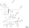
- Fig. 1 shows a schematic, perspective view of different embodiments of an RFID/NFC-system according to the invention.
- Three components 1 are mounted to mounting device 2, for example a top hat rail, especially a DIN rail 2.
- the components 1 comprise a housing 3 and a stationary RFID/NFC-interface 4 that is arranged inside the housing 3 and therefore not visible.
- the components 1 are fixed with one of their side faces to the mounting device, for example a top hat rail, especially as shown a DIN rail 2.
- the stationary RFID/NFC-interface 4 is fixed to the DIN rail 2 with one of its not shown side faces 5, too.
- Fig. 1 shows two different embodiments of a movable RFID/NFC-element 6.
- the first embodiment of an RFID/NFC-element 6' comprises a movable carrier 7' with a second coil 8'.
- the RFID/NFC-element 6' is part of a movable RFID/NFC-interface 9, for example an RFID/NFC-reader/writer, and is thus RFID/NFC-enabled.
- the second embodiment of a movable RFID/NFC-element 6" comprises a movable carrier 7" with a second coil 8".
- the second coil 8" is connected to a third coil 10 arranged on a substrate 11.
- the substrate 11 is designed as a sticker such that the substrate 11 is attached to a portable RFID/NFC-interface 12 by adhesive means.
- the portable RFID/NFC-interface 12 is a mobile phone or smart phone.
- the RFID/NFC-element 6" and the third coil 10 serve as an extension for the portable RFID/NFC-interface 12.
- the movable RFID/NFC-element 6, 6', 6" can be either inserted in an opening 13 of the housing 3 or moved between the components 1.
- the upper surface 14 of the movable carrier 7, 7', 7" faces the not shown upper surface 15 of the not shown stationary carrier 16.
- the movable RFID/NFC-element 6, 6', 6" can be arranged with respect to the stationary RFID/NFC-interface 4 such that a plane of the first coil 17 and a plane of the second coil 8 at least partly face each other.
- each stationary RFID/NFC-interface 4 of each component 1 can communicate with the movable RFID/NFC-element 6, 6', 6" respectively the movable RFID/NFC-interface 9 or the portable RFID/NFC-interface 12.
- Fig. 2 shows a schematic cutaway view of a component 1 comprising a stationary RFID/NFC-interface 4 arranged in a housing 3.
- the stationary RFID/NFC-interface 4 comprises a stationary carrier 16 with a first coil 17 and a RFID/NFC-chip 18 each arranged for example on the upper surface 15 of the stationary carrier 16.
- the housing 3 comprises an opening 13 for inserting a movable RFID/NFC-element 6.
- the housing 3 is fixable to a DIN rail 2 with its side face and therefore the stationary carrier 16 is fixed to the DIN rail 2 with its side face 5, too.
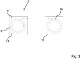
- Fig. 3 shows a first embodiment of a movable RFID/NFC-element 6 in a schematic top view.
- the movable RFID/NFC-element 6 comprises a movable carrier 7 with a second coil 8 arranged for example on its upper surface 14.
- the second coil 8 is connected to a third coil 10.
- Third coil 10 is arranged on a substrate 11.
- the substrate 11 can be a sticker such that the third coil 10 can be adhesively attached to an RFID/NFC-enabled device.
- Fig. 4 shows a second embodiment of a movable RFID/NFC-element 6 in a schematic top view.
- the movable RFID/NFC-element 6 is part of a movable RFID/NFC-interface 9, for example an RFID/NFC-reader.
- the movable RFID/NFC-element 6 comprises a movable carrier 7 with a second coil 8 arranged for example on the upper surface 14 of the movable carrier 7. Further the movable RFID/NFC-element 6 comprises an LCD 19, a battery 20 and keys 21 as operator control.
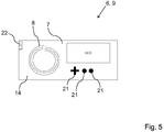
- Fig. 5 shows a third embodiment of a movable RFID/NFC-element 6 in a schematic top view.
- the movable RFID/NFC-element 6 of Fig. 5 differs from the movable RFID/NFC-element 6 of Fig. 4 only in that a power connection 22 instead of a battery 20 is arranged. Therefore the embodiment shown in Fig. 5 is especially suitable for industrial implementation.
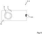
- Fig. 6 shows a third embodiment of a movable RFID/NFC-element 6 in a schematic top view.
- the movable RFID/NFC-element 6 of Fig. 6 differs from the movable RFID/NFC-element 6 of Fig. 4 in that an communication port 23, for example an USB-port, is arranged instead of an LCD 19, a battery 20 and keys 21.
- an communication port 23 for example an USB-port
- the RFID/NFC-reader shown in Fig. 6 is simple in construction and therefore inexpensive to manufacture.
- Fig. 7 shows the parameter setting of a component 1 comprising a stationary RFID/NFC-interface 4 inside the housing 3.
- the stationary RFID/NFC-interface 4 for example an RIFD/NFC-tag, can be parameterized by a RFID/NFC-reader 24 before mounting component 1 to the DIN rail 2.
- Parameter setting can involve storing a serial number in the Electrically Erasable Programmable Read-Only Memory (EEPROM) of the stationary RFID/NFC-interface 4.
- EEPROM Electrically Erasable Programmable Read-Only Memory
- the stationary RFID/NFC-interface 4 will serve as a type label.
- other information can be stored to the stationary RFID/NFC-interface 4, too.
- the stationary RFID/NFC-interface 4 can communicate with the movable RFID/NFC-element 6, for example a portable RFID/NFC-interface 12 or a movable RFID/NFC-interface 9.
- An RFID/NFC-system according to the invention can be utilized for inventory. Further the Firmware of the component 1 can be updated using an RFID/NFC-system of the invention.
Landscapes
- Engineering & Computer Science (AREA)
- Computer Networks & Wireless Communication (AREA)
- Power Engineering (AREA)
- Signal Processing (AREA)
- Computer Hardware Design (AREA)
- Microelectronics & Electronic Packaging (AREA)
- Physics & Mathematics (AREA)
- General Physics & Mathematics (AREA)
- Theoretical Computer Science (AREA)
- Near-Field Transmission Systems (AREA)
Abstract
Description
- The present invention relates to an RFID/NFC-system comprising a stationary RFID/NFC-interface and a movable RFID/NFC-element.
- The present invention further relates to an according RFID/NFC-element.
- Radio-Frequency-identification-systems (RFID-systems) and Near-Field-Communication-systems (NFC-systems) are used for many years to wireless transmit data using inductive coupling. The required magnetic field is generated by antennas which are usually realized as small coils. Since the coils are small they only set up a so-called "near-field" with a range of a few centimeters. Therefore the coils have to be close to each other for transmitting data. The inductive coupling between two coils is strongest when the planes defined by the coils face each other and are oriented parallel to each other.
- It should be noted that in the following the term "RFID/NFC" describes elements of RFID-technology and/or NFC-technology.
- Further hereinafter the term "RFID/NFC-interface" has to be understood in its broadest sense. An RFID/NFC-interface can be any device comprising at least a coil as an RFID/NFC-antenna and an RFID/NFC-chip, i. e. any integrated circuit or other electronic component connected to the coil. For instance an RFID/NFC-interface can be a transmitter, a transponder, a transceiver, a tag or any other device that enables communication using RFID/NFC-technology.
- In electrical engineering components are usually mounted to a mounting device, for example a top hat rail, especially a DIN rail. A stationary RFID/NFC-interface that is arranged on the circuit board of this component cannot communicate with a second, mobile RFID/NFC-interface since there is not enough space to bring the coils of the RFID/NFC-interfaces close enough together. Further the planes defined by the coils will neither be oriented parallel to each other nor will face each other. Thus an inductive coupling is impossible. For communicating with the stationary RFID/NFC-interface the component has to be dismounted.
- An RFID/NFC-system that solves this problem is disclosed in
DE 20 2012 012 880 U1 . The disclosed RFID/NFC-system comprises a stationary coil wherein the plane defined by this coil is arranged orthogonal to the circuit board of the component. This system is very complicate to manufacture and thus expensive. - It is therefore an object of the present invention to improve and further develop an RFID/NFC-system and an according RFID/NFC-element such that communication with the stationary RFID/NFC-interface is possible when the stationary RFID/NFC-device is fixed to a mounting device. Further the RFID/NFC-system and the RFID/NFC-element has to be realized with easy constructive elements and has to be inexpensive to manufacture.
- In accordance with the invention, the aforementioned object is accomplished by a RFID/NFC-system comprising the features of
claim 1. According to this claim, such an RFID/NFC-system comprises a stationary RFID/NFC-interface and a movable RFID/NFC-element, wherein the stationary RFID/NFC-interface comprises a stationary carrier with a first coil arranged for example on its upper surface or on its lower surface and connected to a first RFID/NFC-chip, wherein the stationary carrier is fixed with one of its side faces to a mounting device, wherein the movable RFID/NFC-element comprises a movable carrier with a second coil arranged for example on its upper surface or on its lower surface, wherein the second coil is connected or connectable to a second RFID/NFC-chip and wherein the movable RFID/NFC-element can be moved with respect to the stationary RFID/NFC-interface such that the upper surface or the lower surface of the movable carrier and the upper surface or the lower surface of the stationary carrier at least partly face each other such that signals can be transferred between the first coil and the second coil. - According to the invention it has first been recognized that the aforementioned problem can be solved in a very easy way, if the mobile RFID/NFC-element can be arranged at least partly beneath the upper or lower surface of the stationary RFID/NFC-interface. With an according arrangement the coils can be brought together close enough for inductive coupling, especially the planes of the coils can be arranged at least partly parallel to each other. Further it has been recognized that it is sufficient to move an RFID/NFC-element comprising only a carrier and a coil with respect to the stationary RFID/NFC-interface. The RFID/NFC-element can be connected or connectable to an RFID/NFC-chip.
- To achieve an even better inductive coupling the movable RFID/NFC-element could be arranged with respect to the stationary RFID/NFC-interface such that a plane of the first coil and a plane of the second coil at least partly face each other. Alternatively or additionally the planes of the first coil and the second coil could be arranged parallel to each other.
- In a preferred manner the stationary carrier and/or the movable carrier can be a printed circuit board, wherein the first coil and/or the second coil could be etched or printed onto the printed circuit board. Alternatively or additionally the first coil and/or the second coil can be a planar coil. This will make the RFID/NFC-system easy to manufacture and therefore inexpensive. Further it is possible that the first coil and/or the second coil are arranged inside the stationary carrier and/or the movable carrier, wherein additionally the stationary carrier and/or the movable carrier can be a multilayer board.
- In view of an easy mounting of the stationary RFID/NFC-interface the mounting device can be for example a top hat rail, especially a DIN rail.
- Especially in regard to an industrial implementation at least two stationary RFID/NFC-interfaces can be fixed to the mounting device. Even more than two stationary RFID/NFC-interfaces can be fixed to the mounting device as long as the movable RFID/NFC-element can be arranged according to the invention with respect to each of the RFID/NFC-interfaces. In a preferred embodiment the RFID/NFC-element can be moved between the stationary RFID/NFC-interfaces. With an according construction the movable RFID/NFC-element can be moved with respect to the stationary RFID/NFC-interface such that the upper surface or the lower surface of the movable carrier and the upper surface or the lower surface of the stationary carrier at least partly face each other such that signals can be transferred between the first coil and the second coil.
- In particular in industrial implementation it can be necessary for reasons of safety to prevent the component and/or stationary RFID/NFC-interface from being touched. Therefore the stationary RFID/NFC-interface can comprise a housing with an opening for inserting the movable RFID/NFC-element. With this construction a reliable inductive coupling is achieved without being at risk of touching the stationary RFID/NFC-interface or other parts of the component.
- Preferably the second coil of the mobile RFID/NFC-element is connected to a third coil for transmitting signals to or receiving signals from a portable RFID/NFC-interface. Put another way the mobile RFID/NFC-element serves as an extension of a portable RFID/NFC-interface. With an according extension all kinds of portable RFID/NFC-interfaces can be used for communicating with the stationary RFID/NFC-interface. Such portable RFID/NFC-interfaces can be a portable computer, a mobile phone, a smart phone or any other RFID/NFC-enable mobile device. It is further possible that the second coil and the third coil are arranged on the same carrier, for example a printed circuit board. The second coil and the third coil can be printed or etched onto the printed circuit board as planar coils and connected to each other.
- In a preferred embodiment the third coil can be attached to the portable RFID/NFC-interface, especially an RFID/NFC-enabled mobile device, by adhesive means or by mechanical means. The third coil can be arranged on a substrate like a foil wherein at least one side of the foil comprises an adhesive such that the foil can be glued or stuck to the portable RFID/NFC-interface, for example an RFID/NFC-enabled mobile device.
- Furthermore the movable RFID/NFC-element can be a part of a movable RFID/NFC-interface comprising an RFID/NFC-chip. Put another way the movable RFID/NFC-element can be a part of an RFID/NFC-enabled device such as an RFID/NFC-reader. The movable RFID/NFC-interface can comprise a display, particularly a liquid crystal display (LCD), and/or an operator control, particularly at least one key or button, and/or a communication port, for example an USB-port, and/or a power connection.
- In a preferred embodiment the movable RFID/NFC-element, respectively the movable RFID/NFC-interface or movable RFID/NFC-reader, can be shielded against disturbing electromagnetic radiation with a foil, preferably made of ferrit.
- The aforementioned object is further accomplished by an RFID/NFC-element comprising the features of
claim 11. With regard to the advantages of an according RFID/NFC-element it is to be referred to the aforementioned description of the RFID/NFC-system. - There are several ways how to design and further develop the teaching of the present invention in an advantageous way. To this end it is to be referred to the patent claims subordinate to
patent claim 1 as well as toindependent claim 11 on the one hand and to the following explanation of preferred embodiments of the invention by way of example, illustrated by the figure on the other hand. In connection with the explanation of the preferred embodiments of the invention by the aid of the figure, generally preferred embodiments and further developments of the teaching will be explained. In the drawing - Fig. 1
- is a schematic, perspective view of different embodiments of an RFID/NFC-system according to the invention,
- Fig. 2
- is a schematic cutaway view of a component comprising an RFID/NFC-interface according to the invention,
- Fig. 3
- is a schematic top view of a first embodiment of an RFID/NFC-element according to the invention,
- Fig. 4
- is a schematic top view of a second embodiment of an RFID/NFC-element according to the invention,
- Fig. 5
- is a schematic top view of a third embodiment of an RFID/NFC-element according to the invention,
- Fig. 6
- is a schematic top view of a fourth embodiment of an RFID/NFC-element according to the invention, and
- Fig. 7
- is a schematic view of the parameter setting of a stationary RFID/NFC-element according to the invention.
-
Fig. 1 shows a schematic, perspective view of different embodiments of an RFID/NFC-system according to the invention. Threecomponents 1 are mounted to mountingdevice 2, for example a top hat rail, especially aDIN rail 2. Thecomponents 1 comprise ahousing 3 and a stationary RFID/NFC-interface 4 that is arranged inside thehousing 3 and therefore not visible. Thecomponents 1 are fixed with one of their side faces to the mounting device, for example a top hat rail, especially as shown aDIN rail 2. Hence the stationary RFID/NFC-interface 4 is fixed to theDIN rail 2 with one of its not shown side faces 5, too. -
Fig. 1 shows two different embodiments of a movable RFID/NFC-element 6. The first embodiment of an RFID/NFC-element 6' comprises a movable carrier 7' with a second coil 8'. The RFID/NFC-element 6' is part of a movable RFID/NFC-interface 9, for example an RFID/NFC-reader/writer, and is thus RFID/NFC-enabled. - The second embodiment of a movable RFID/NFC-
element 6" comprises amovable carrier 7" with asecond coil 8". Thesecond coil 8" is connected to athird coil 10 arranged on asubstrate 11. Thesubstrate 11 is designed as a sticker such that thesubstrate 11 is attached to a portable RFID/NFC-interface 12 by adhesive means. In this embodiment the portable RFID/NFC-interface 12 is a mobile phone or smart phone. The RFID/NFC-element 6" and thethird coil 10 serve as an extension for the portable RFID/NFC-interface 12. - As can further be seen from
Fig. 1 the movable RFID/NFC-element opening 13 of thehousing 3 or moved between thecomponents 1. When the RFID/NFC-element housing 3 or between thecomponents 1, theupper surface 14 of themovable carrier upper surface 15 of the not shownstationary carrier 16. Depending on the position of the not shownfirst coil 17 arranged on thestationary carrier 16 the movable RFID/NFC-element interface 4 such that a plane of thefirst coil 17 and a plane of thesecond coil 8 at least partly face each other. This leads to a very good inductive coupling between thefirst coil 17 and thesecond coil 8. Due to the good inductive coupling thefirst coil 17 and/or thesecond coil 8 can be operated with low power. Thereby the transmitting power of thefirst coil 17 and/or thesecond coil 8 is low such that the magnetic field generated by thefirst coil 17 and/or thesecond coil 8 will not interfere with adjacent devices. Hence each stationary RFID/NFC-interface 4 of eachcomponent 1 can communicate with the movable RFID/NFC-element interface 12. -
Fig. 2 shows a schematic cutaway view of acomponent 1 comprising a stationary RFID/NFC-interface 4 arranged in ahousing 3. The stationary RFID/NFC-interface 4 comprises astationary carrier 16 with afirst coil 17 and a RFID/NFC-chip 18 each arranged for example on theupper surface 15 of thestationary carrier 16. Thehousing 3 comprises anopening 13 for inserting a movable RFID/NFC-element 6. Thehousing 3 is fixable to aDIN rail 2 with its side face and therefore thestationary carrier 16 is fixed to theDIN rail 2 with itsside face 5, too. -
Fig. 3 shows a first embodiment of a movable RFID/NFC-element 6 in a schematic top view. The movable RFID/NFC-element 6 comprises amovable carrier 7 with asecond coil 8 arranged for example on itsupper surface 14. Thesecond coil 8 is connected to athird coil 10.Third coil 10 is arranged on asubstrate 11. Thesubstrate 11 can be a sticker such that thethird coil 10 can be adhesively attached to an RFID/NFC-enabled device. -
Fig. 4 shows a second embodiment of a movable RFID/NFC-element 6 in a schematic top view. The movable RFID/NFC-element 6 is part of a movable RFID/NFC-interface 9, for example an RFID/NFC-reader. The movable RFID/NFC-element 6 comprises amovable carrier 7 with asecond coil 8 arranged for example on theupper surface 14 of themovable carrier 7. Further the movable RFID/NFC-element 6 comprises anLCD 19, abattery 20 andkeys 21 as operator control. -
Fig. 5 shows a third embodiment of a movable RFID/NFC-element 6 in a schematic top view. The movable RFID/NFC-element 6 ofFig. 5 differs from the movable RFID/NFC-element 6 ofFig. 4 only in that apower connection 22 instead of abattery 20 is arranged. Therefore the embodiment shown inFig. 5 is especially suitable for industrial implementation. -
Fig. 6 shows a third embodiment of a movable RFID/NFC-element 6 in a schematic top view. The movable RFID/NFC-element 6 ofFig. 6 differs from the movable RFID/NFC-element 6 ofFig. 4 in that ancommunication port 23, for example an USB-port, is arranged instead of anLCD 19, abattery 20 andkeys 21. Hence the RFID/NFC-reader shown inFig. 6 is simple in construction and therefore inexpensive to manufacture. -
Fig. 7 shows the parameter setting of acomponent 1 comprising a stationary RFID/NFC-interface 4 inside thehousing 3. The stationary RFID/NFC-interface 4, for example an RIFD/NFC-tag, can be parameterized by a RFID/NFC-reader 24 before mountingcomponent 1 to theDIN rail 2. Parameter setting can involve storing a serial number in the Electrically Erasable Programmable Read-Only Memory (EEPROM) of the stationary RFID/NFC-interface 4. Hence the stationary RFID/NFC-interface 4 will serve as a type label. Alternatively or additionally other information can be stored to the stationary RFID/NFC-interface 4, too. After mounting thecomponent 1 to theDIN rail 2 the stationary RFID/NFC-interface 4 can communicate with the movable RFID/NFC-element 6, for example a portable RFID/NFC-interface 12 or a movable RFID/NFC-interface 9. An RFID/NFC-system according to the invention can be utilized for inventory. Further the Firmware of thecomponent 1 can be updated using an RFID/NFC-system of the invention. - Many modifications and other embodiments of the invention set forth herein will come to mind to the one skilled in the art to which the invention pertains having the benefit of the teachings presented in the foregoing description and the associated drawings. Therefore, it is to be understood that the invention is not to be limited to the specific embodiments disclosed and that modifications and other embodiments are intended to be included within the scope of the appended claims. Although specific terms are employed herein, they are used in a generic and descriptive sense only and not for purposes of limitation.
-
- 1
- component
- 2
- mounting device, DIN rail
- 3
- housing
- 4
- stationary RFID/NFC-interface
- 5
- side face
- 6, 6', 6"
- movable RFID/NFC-element
- 7, 7', 7"
- movable carrier
- 8, 8', 8"
- second coil
- 9
- movable RFID/NFC-interface
- 10
- third coil
- 11
- substrate
- 12
- portable RFID/NFC-interface
- 13
- opening
- 14
- upper surface (movable carrier)
- 15
- upper surface (stationary carrier)
- 16
- stationary carrier
- 17
- first coil
- 18
- RFID/NFC-chip
- 19
- LCD
- 20
- battery
- 21
- operator control (keys)
- 22
- power connection
- 23
- communication port
- 24
- RFID/NFC-reader
Claims (12)
- RFID/NFC-system comprising a stationary RFID/NFC-interface (4) and a movable RFID/NFC-element (6, 6', 6"), wherein the stationary RFID/NFC-interface (4) comprises a stationary carrier (16) with a first coil (17) arranged for example on its upper surface (15) or on its lower surface and connected to a first RFID/NFC-chip (18), wherein the stationary carrier (16) is fixed with one of its side faces (5) to a mounting device (2), wherein the movable RFID/NFC-element (6, 6', 6") comprises a movable carrier (7, 7', 7") with a second coil (8, 8', 8") arranged for example on its upper surface (14) or on its lower surface, wherein the second coil (8, 8', 8") is connected or connectable to a second RFID/NFC-chip and wherein the movable RFID/NFC-element (6, 6', 6") can be moved with respect to the stationary RFID/NFC-interface (4) such that the upper surface (14) or the lower surface of the movable carrier (7, 7', 7") and the upper surface (15) or the lower surface of the stationary carrier (16) at least partly face each other such that signals can be transferred between the first coil (17) and the second coil (8, 8', 8").
- RFID/NFC-system according to claim 1, wherein the movable RFID/NFC-element (6, 6', 6") can be arranged with respect to the stationary RDIF/NFC-interface (4) such that a plane of the first coil (17) and a plane of the second coil (8, 8', 8") at least partly face each other.
- RFID/NFC-system according to claim 1 or 2, wherein the stationary carrier (16) and/or the movable carrier (7, 7', 7") is a printed circuit board and wherein the first coil (17) and/or the second coil (8, 8', 8") is etched or printed, preferably as a planar coil, onto the printed circuit board.
- RFID/NFC-system according to one of claims 1 to 3, wherein the mounting device (2) is for example a top hat rail, especially a DIN rail (2).
- RFID/NFC-system according to one of claims 1 to 4, wherein at least two stationary RFID/NFC-interfaces (4) are fixed to the mounting device (2).
- RFID/NFC-system according to claim 5, wherein the movable RFID/NFC-element (6, 6', 6") can be moved between the stationary RFID/NFC-interfaces (4).
- RFID/NFC-system according to one of claims 1 to 6, wherein the stationary RFID/NFC-interface (4) comprises a housing (3) with an opening (13) for inserting the movable RFID/NFC-element (6, 6', 6").
- RFID/NFC-system according to one of claims 1 to 7, wherein the second coil (8, 8', 8") is connected to a third coil (10) for transmitting signals to or receiving signals from a portable RFID/NFC-interface (12), in particular a portable computer, a mobile phone, a smartphone or any other RFID/NFC-enabled mobile device.
- RFID/NFC-system according to claim 8, wherein the third coil (10) is fixed to the portable RFID/NFC-interface (12) by adhesive means or by mechanical means.
- RFID/NFC-system according to one of claim 1 to 7, wherein the movable RFID/NFC-element (6, 6', 6") is part of a movable RFID/NFC-interface (9) comprising an RFID/NFC-chip.
- RFID/NFC-system according to claim 10, wherein the movable RFID/NFC-interface (9) comprises a display, particularly a liquid crystal display (LCD) (19), and/or a operator control (21), particularly at least one key (21) or button, and/or a battery (20) and/or a communication-port (23), for example a USB-port, and/or a power connection (22).
- RFID/NFC-element (6, 6', 6") according to one of claims 1 to 11.
Priority Applications (1)
| Application Number | Priority Date | Filing Date | Title |
|---|---|---|---|
| EP15195870.9A EP3046268A1 (en) | 2014-11-25 | 2014-11-25 | An rfid/nfc-system and an rfid/nfc-element |
Applications Claiming Priority (3)
| Application Number | Priority Date | Filing Date | Title |
|---|---|---|---|
| EP15195870.9A EP3046268A1 (en) | 2014-11-25 | 2014-11-25 | An rfid/nfc-system and an rfid/nfc-element |
| EP14821078.4A EP3042453B1 (en) | 2014-11-25 | 2014-11-25 | An rfid/nfc-system |
| PCT/EP2014/075532 WO2016082865A1 (en) | 2014-11-25 | 2014-11-25 | An rfid/nfc-system and an rfid/nfc-element |
Related Parent Applications (2)
| Application Number | Title | Priority Date | Filing Date |
|---|---|---|---|
| EP14821078.4A Division-Into EP3042453B1 (en) | 2014-11-25 | 2014-11-25 | An rfid/nfc-system |
| EP14821078.4A Division EP3042453B1 (en) | 2014-11-25 | 2014-11-25 | An rfid/nfc-system |
Publications (1)
| Publication Number | Publication Date |
|---|---|
| EP3046268A1 true EP3046268A1 (en) | 2016-07-20 |
Family
ID=52273081
Family Applications (2)
| Application Number | Title | Priority Date | Filing Date |
|---|---|---|---|
| EP14821078.4A Active EP3042453B1 (en) | 2014-11-25 | 2014-11-25 | An rfid/nfc-system |
| EP15195870.9A Withdrawn EP3046268A1 (en) | 2014-11-25 | 2014-11-25 | An rfid/nfc-system and an rfid/nfc-element |
Family Applications Before (1)
| Application Number | Title | Priority Date | Filing Date |
|---|---|---|---|
| EP14821078.4A Active EP3042453B1 (en) | 2014-11-25 | 2014-11-25 | An rfid/nfc-system |
Country Status (3)
| Country | Link |
|---|---|
| US (1) | US9871562B2 (en) |
| EP (2) | EP3042453B1 (en) |
| WO (1) | WO2016082865A1 (en) |
Cited By (1)
| Publication number | Priority date | Publication date | Assignee | Title |
|---|---|---|---|---|
| US11087101B2 (en) | 2017-11-03 | 2021-08-10 | Pap Investments, Ltd. | Dual frequency NFC/RFID card for self service baggage check and method |
Families Citing this family (1)
| Publication number | Priority date | Publication date | Assignee | Title |
|---|---|---|---|---|
| DE102016209133A1 (en) * | 2016-05-25 | 2017-11-30 | BSH Hausgeräte GmbH | Cooking appliance with short-range radio interface |
Citations (8)
| Publication number | Priority date | Publication date | Assignee | Title |
|---|---|---|---|---|
| DE10003842A1 (en) * | 2000-01-30 | 2001-08-02 | Fraba Ag | Radio transmission and evaluation device for e.g. monitoring of fill level and tear of winding materials on rotating machine, has movable device that can move to movement path set at three space directions |
| US20070008140A1 (en) * | 2005-06-14 | 2007-01-11 | Mikko Saarisalo | Tag multiplication |
| EP2299382A1 (en) * | 2009-09-09 | 2011-03-23 | I.CAR S.r.l. | Improved portable radio frequency reader for reading and writing data in a microchip applied to a vehicle |
| WO2014038107A1 (en) * | 2012-09-06 | 2014-03-13 | パナソニック 株式会社 | Contactless power-supply system, contactless adapter, and power-supply device |
| DE202012012880U1 (en) | 2012-08-01 | 2014-04-22 | Phoenix Contact Gmbh & Co. Kg | coil system |
| US20140159848A1 (en) * | 2012-12-10 | 2014-06-12 | Anand S Konanur | Cascaded coils for multi-surface coverage in near field communication |
| WO2014111502A1 (en) * | 2013-01-17 | 2014-07-24 | Baumann/Holding/1886 Gmbh | Device for the wireless transmission of electrical power |
| WO2014179869A1 (en) * | 2013-05-10 | 2014-11-13 | Cynetic Designs Ltd. | Inductively coupled wireless power and data for a garment via a dongle |
Family Cites Families (4)
| Publication number | Priority date | Publication date | Assignee | Title |
|---|---|---|---|---|
| US8686685B2 (en) * | 2009-12-25 | 2014-04-01 | Golba, Llc | Secure apparatus for wirelessly transferring power and communicating with one or more slave devices |
| DE102012000408A1 (en) * | 2012-01-12 | 2013-07-18 | Phoenix Contact Gmbh & Co. Kg | Resonant inductive power supply device |
| DE102012110170B4 (en) * | 2012-10-24 | 2018-05-24 | Phoenix Contact Gmbh & Co. Kg | Modular bus system for the transmission of data and / or energy |
| DE102012110173A1 (en) * | 2012-10-24 | 2014-06-12 | Phoenix Contact Gmbh & Co. Kg | Modular electronic system and bus participants |
-
2014
- 2014-11-25 WO PCT/EP2014/075532 patent/WO2016082865A1/en not_active Ceased
- 2014-11-25 US US15/118,553 patent/US9871562B2/en active Active
- 2014-11-25 EP EP14821078.4A patent/EP3042453B1/en active Active
- 2014-11-25 EP EP15195870.9A patent/EP3046268A1/en not_active Withdrawn
Patent Citations (8)
| Publication number | Priority date | Publication date | Assignee | Title |
|---|---|---|---|---|
| DE10003842A1 (en) * | 2000-01-30 | 2001-08-02 | Fraba Ag | Radio transmission and evaluation device for e.g. monitoring of fill level and tear of winding materials on rotating machine, has movable device that can move to movement path set at three space directions |
| US20070008140A1 (en) * | 2005-06-14 | 2007-01-11 | Mikko Saarisalo | Tag multiplication |
| EP2299382A1 (en) * | 2009-09-09 | 2011-03-23 | I.CAR S.r.l. | Improved portable radio frequency reader for reading and writing data in a microchip applied to a vehicle |
| DE202012012880U1 (en) | 2012-08-01 | 2014-04-22 | Phoenix Contact Gmbh & Co. Kg | coil system |
| WO2014038107A1 (en) * | 2012-09-06 | 2014-03-13 | パナソニック 株式会社 | Contactless power-supply system, contactless adapter, and power-supply device |
| US20140159848A1 (en) * | 2012-12-10 | 2014-06-12 | Anand S Konanur | Cascaded coils for multi-surface coverage in near field communication |
| WO2014111502A1 (en) * | 2013-01-17 | 2014-07-24 | Baumann/Holding/1886 Gmbh | Device for the wireless transmission of electrical power |
| WO2014179869A1 (en) * | 2013-05-10 | 2014-11-13 | Cynetic Designs Ltd. | Inductively coupled wireless power and data for a garment via a dongle |
Cited By (1)
| Publication number | Priority date | Publication date | Assignee | Title |
|---|---|---|---|---|
| US11087101B2 (en) | 2017-11-03 | 2021-08-10 | Pap Investments, Ltd. | Dual frequency NFC/RFID card for self service baggage check and method |
Also Published As
| Publication number | Publication date |
|---|---|
| US9871562B2 (en) | 2018-01-16 |
| WO2016082865A1 (en) | 2016-06-02 |
| EP3042453B1 (en) | 2018-02-28 |
| US20170054474A1 (en) | 2017-02-23 |
| EP3042453A1 (en) | 2016-07-13 |
Similar Documents
| Publication | Publication Date | Title |
|---|---|---|
| JP2006302219A (en) | RFID tag communication range setting device | |
| US20140197930A1 (en) | Field Device for Automation Technology | |
| WO2008033223A3 (en) | Radio frequency identification (rfid) system for item level inventory | |
| US10680313B2 (en) | Stacked antenna module | |
| EP1837798A3 (en) | RFID bridge antenna | |
| EP1901393A4 (en) | ANTENNA DEVICE | |
| US10691994B2 (en) | Handheld power tool and amplifier antenna | |
| KR101715901B1 (en) | Antenna module | |
| EP3042453B1 (en) | An rfid/nfc-system | |
| JP2014209303A5 (en) | ||
| JP2012119830A (en) | Explosion-proof data communication system | |
| WO2005106767A1 (en) | Electronic device | |
| CN102714925B (en) | man-machine dialogue system | |
| EP2852128A1 (en) | Pendant and terminal | |
| US11238434B2 (en) | Active peripheral device and electronic payment terminal | |
| CN103198351B (en) | Cylindrical electronic tag | |
| US20130256413A1 (en) | Reading an rfid tag associated with a rear connector via an electromagnetic loop induction system | |
| KR102128005B1 (en) | Antenna device and method of operation thereof | |
| TW200717332A (en) | RFID tag and RFID tag manufacturing method | |
| WO2014121300A3 (en) | Photonic data transfer assembly | |
| KR20150122040A (en) | Electronic shelf label tag with embeded nfc function | |
| KR101634371B1 (en) | Near Field Communication Touch-Pad | |
| JP2017135443A (en) | Jacket type device and portable communication terminal with jacket type device | |
| US10593491B2 (en) | Apparatus with membrane panel having close-proximity communication antenna | |
| US10915127B2 (en) | Parameterizable energy supply device |
Legal Events
| Date | Code | Title | Description |
|---|---|---|---|
| PUAI | Public reference made under article 153(3) epc to a published international application that has entered the european phase |
Free format text: ORIGINAL CODE: 0009012 |
|
| AC | Divisional application: reference to earlier application |
Ref document number: 3042453 Country of ref document: EP Kind code of ref document: P |
|
| AK | Designated contracting states |
Kind code of ref document: A1 Designated state(s): AL AT BE BG CH CY CZ DE DK EE ES FI FR GB GR HR HU IE IS IT LI LT LU LV MC MK MT NL NO PL PT RO RS SE SI SK SM TR |
|
| AX | Request for extension of the european patent |
Extension state: BA ME |
|
| 17P | Request for examination filed |
Effective date: 20160628 |
|
| RBV | Designated contracting states (corrected) |
Designated state(s): AL AT BE BG CH CY CZ DE DK EE ES FI FR GB GR HR HU IE IS IT LI LT LU LV MC MK MT NL NO PL PT RO RS SE SI SK SM TR |
|
| STAA | Information on the status of an ep patent application or granted ep patent |
Free format text: STATUS: EXAMINATION IS IN PROGRESS |
|
| 17Q | First examination report despatched |
Effective date: 20170206 |
|
| RIC1 | Information provided on ipc code assigned before grant |
Ipc: H04B 5/00 20060101AFI20170502BHEP Ipc: H01F 27/28 20060101ALI20170502BHEP Ipc: H01F 38/14 20060101ALI20170502BHEP |
|
| STAA | Information on the status of an ep patent application or granted ep patent |
Free format text: STATUS: THE APPLICATION IS DEEMED TO BE WITHDRAWN |
|
| 18D | Application deemed to be withdrawn |
Effective date: 20170927 |